Abstract
The current contact of pyro-breakers must rapidly interrupt current when the superconducting magnet loses its superconductivity. To enhance the microsecond-scale current-breaking capability of pyro-breakers in nuclear fusion devices, this study investigates the impact of current contact notch structures on dynamic fracture behavior. Through multi-physics field modeling and controlled explosive testing, it is revealed for the first time that the rectangular-notch structure demonstrates enhanced fracture performance relative to the V-notch configuration under explosive impact loading conditions, achieving a 27.3% reduction in fracture initiation time alongside a 47.5% increase in crack propagation width. These findings provide a robust theoretical basis for designing pyro-breakers with enhanced fast-break capabilities in fusion devices.
1. Introduction
In magnetic confinement fusion devices, superconducting magnets serve as the core component for efficient plasma confinement, operating under conditions of extremely low temperatures and high current [1,2,3]. In the event of a quench, a localized region rapidly transitions from superconducting to normally conducting, generating a substantial amount of Joule heat in a short time [4]. If the current is not interrupted promptly, the resulting thermal stress may cause magnet burnout or even trigger a systemic catastrophe [5,6,7]. Consequently, the quench protection system is equipped with pyro-breakers as a backup safeguard, which are designed to disconnect current contacts within microseconds to rapidly cut off current flow and dissipate energy [8,9,10].
The concept of the pyro-breaker was first pioneered by M. Manzuk in its structural design. Subsequently, an engineering-grade prototype capable of withstanding 70 kA currents was successfully developed for the International Thermonuclear Experimental Reactor (ITER) project [11,12]. Building upon this foundation, Tang’s team systematically optimized the structure, ultimately developing a new-generation prototype with a maximum current-carrying capacity of 100 kA [13,14]. The core performance metrics of pyro-breakers primarily depend on their response time and fusing reliability. Current contacts typically employ cylindrical copper structures due to their exceptional electrical conductivity and thermal stability. By incorporating micro-notches on the contact’s outer surface, this design enables controlled disconnection under implosion loads. This approach ensures reliable current interruption while precisely controlling the fracture process.
Currently, the mainstream international thermal breaker contacts widely adopt the V-notch design proposed by M. Manzuk, which achieves controlled fusing through stress concentration effects [15]. However, despite the widespread adoption of V-notch, their fracture mechanisms lack a systematic theoretical analysis and experimental research framework. Particularly, failure modes under extreme conditions such as high temperatures and strong electromagnetic fields require further investigation. This lag in theoretical research has, to some extent, constrained the expansion of pyro-breakers into higher current ratings and more complex operational scenarios.
In this study, the dynamic fracture process of the current contact in pyro-breakers is comprehensively analyzed from the perspective of fracture mechanics. By employing LS-DYNA numerical simulation, the stress-time curve during the contact fracture is obtained [16,17,18,19,20]. The study reveals, for the first time, the dual advantages of a rectangular notch (R-notch) over the conventional V-notch in fracture control. Specifically, the R-notch reduces the fracture time by approximately 27.3 per cent, which significantly increases the fracture rate of pyro-breakers. Additionally, it increases the fracture width by 47.5%, which contributes to improved isolation voltage capability. Prototype testing confirms that the optimized R-notch structure demonstrates superior fracture performance compared to the traditional V-notch design. These findings not only provide a theoretical foundation for the breaking mechanism of current contacts in pyro-breakers used in superconducting protection systems but also offer valuable guidance for the design of contacts in other types of circuit breakers.
2. Materials and Methods
2.1. The Structure of a Pyro-Breaker
The structure of the pyro-breaker is illustrated in Figure 1. Functionally, it is divided into two main units: the isolated unit and the current unit. The isolated unit comprises the isolated contact, upper current lead, insulation cylinder, explosion chamber 1, and explosive tube 1. The current unit consists of the epoxy support plate, lower current lead, and cutting grid. Additionally, the current conversion unit includes an epoxy support plate, lower current lead, cutting grid, current contacts, explosion chamber 2, and explosive tube 2.
Figure 1.
Structure of a pyro-breaker.
The structural design of the pyro-breaker utilizes a series connection of the upper and lower current leads, which are effectively integrated into the main circuit. In this configuration, the current initially flows through the upper current lead, then passes through the isolated contact to the center current lead. From there, the current flows through the current contact, ensuring efficient current conduction before exiting through the lower current lead. Upon detection of the quench signal, the detonation device immediately sends a detonation signal to the detonator and explosives. The resulting explosion generates a powerful blast wave that quickly propagates through the transmission medium to the contact surface. The shock wave causes the current contact to be divided into several segments, each with a distinct gap. This separation leads to the formation of a high-voltage arc between the segments, which facilitates the rapid transfer of circuit current to the discharge resistance. The arc is extinguished by high-velocity deionized water from explosion chamber 2, while the gap between the segments is completely filled with uncontaminated deionized water. This process maintains insulation for several milliseconds, ensuring the successful interruption of the circuit. Simultaneously, the isolated insulation cylinder, subjected to the blast pressure from explosion chamber 1, moves downward, severing the isolated contact and providing long-term high-strength insulation through the insulation cylinder.
2.2. Current Unit Modeling
As illustrated in Figure 1, the pyro-breaker current contact adopts a copper thin-walled cylindrical configuration featuring seven equally spaced weakening notches on its outer surface. Each notch maintains dimensional specifications of 0.5 mm in depth and 1 mm in height. Current implementations in major tokamak devices (ITER, International Thermonuclear Experimental Reactor, an international collaboration involving 35 countries including China, EU, India, Japan, South Korea, Russia, and the US, is based in Cadarache, France; JT-60SA Japan Torus-60 Super Advanced, jointly developed by Japan and the EU, operates in Naka, Ibaraki, Japan; and K-STAR, Korea Superconducting Tokamak Advanced Research, built by South Korea’s National Fusion Research Institute, is located in Daejeon, Republic of Korea) predominantly employ V-notch geometries. This study proposes an innovative R-notch configuration, with comparative analysis of dynamic fracture characteristics between the two notch types conducted through integrated LS-DYNA simulations and experimental detonation tests.
The fracture process of the current contact primarily involves two nonlinear problems: one is the near-field explosion problem, in which the blast wave and explosion products interact with the water; the other is the fluid-solid coupling problem, in which the shock wave in the water interacts with the copper cylinder. Due to the complexity of these nonlinear problems involving multiple material interactions, obtaining an analytical solution is challenging. Therefore, this study employs LS-DYNA R14.1.0 simulation software to analyze the dynamic fracture process of the contact structure under different notch configurations, subjected to blast shock wave loading, using a fluid-solid coupling algorithm.
Due to the structural symmetry of the explosive and current contact, and to reduce computational time, the simulation is modeled using only a single fracture unit. Based on the actual structure of the pyro-breaker, the numerical model consists of five components: explosive, water, air, copper, and epoxy. The model dimensions are consistent with those of the physical prototype, as shown in Figure 2. The explosive is represented as an elongated cylinder with a radius of 0.5 cm and a height of 4 cm. The copper cylinder has a wall thickness of 0.2 cm and a height of 4 cm, while the epoxy component is 1 cm in height. The surrounding air domain has a diameter of 10 cm. To evaluate the fracture performance, both V-notch and R-notch are introduced at the midpoint of the current contact as intentional weak points. Except for the notch geometry, all other parameters are kept identical for comparative analysis.
Figure 2.
Current unit simulation model diagram.
The model adopts a unit system based on cm-g-µs, where the explosive, water, and air are represented using Eulerian meshes, while the copper and epoxy cutting grids are modeled using Lagrangian meshes. The grid model is shown in Figure 3, where the explosive grid size is 0.05 cm, the water grid size is 0.08 cm, the air grid size is 0.08 cm, the epoxy grid size is 0.05 cm, and the copper grid size is 0.025 cm. This approach allows for precise tracking of the deformation, displacement, and other mechanical responses of the solid components, accurately reflecting their physical behavior under explosive impact. A fluid-solid coupling algorithm is applied between the Eulerian and Lagrangian grids, enabling the bidirectional transfer of forces, displacements, and other physical quantities between the fluid and solid domains, ensuring a cohesive and coordinated simulation system. Fixed constraints are applied to the periphery of the epoxy cutting grid to effectively limit its displacement and simulate real-world working conditions. Non-reflective boundaries are set at the upper and peripheral ends of the air domain to prevent wave reflections from interfering with the simulation results. This study comprehensively simulates the entire dynamic process of the current unit, from the initial stable state through explosion impact, energy release, pressure transfer, and disconnection. Ultimately, the differences in fracture time and fracture spacing between the two contact structures are successfully revealed.
Figure 3.
(a,b) Simulation mesh model diagram.
The explosive used in this study is high-density RDX, modeled using the MAT_HIGH_EXPLOSIVE_BURN material model. The Jones-Wilkins-Lee (JWL) equation of state is employed to describe the relationship between explosion pressure, internal energy, and relative volume. The equation is expressed as follows:
where p is the burst pressure, A, B, R1, R2 and ω are parameters obtained by experimental fitting, as shown in Table 1.

Table 1.
Material parameters of RDX.
The deformation and rupture of the copper are the primary focus of this study. Given that the copper undergoes a wide range of strains, strain rates, and temperatures under explosive loading, the Johnson-Cook material model is employed. The equation is expressed as follows:
where σ is the flow stress, is the equivalent plastic strain rate, is the homologous temperature, and A, B, C, m, and n are the material constants determined experimentally, which are shown in Table 2.
Table 2.
Material parameters of copper.
2.3. Analysis of Numerical Simulation
As illustrated in Figure 4, the propagation process of the shock wave following an explosive detonation is demonstrated using a V-notch as an example. The detonation commenced at time zero at the central point atop the explosive charge. At 1.5 µs, high-temperature, high-pressure gaseous detonation products began forming ahead of the detonation wavefront, expanding radially outward. Concurrently, the detonation wave traversed the explosive column and entered the surrounding aqueous medium, generating a secondary shock wave. The detonation wave velocity was approximately 4.5 times the speed of sound in water.
Figure 4.
V-notch blast shock wave propagation.
By 7.5 µs, the blast wave reaches the base of the explosive charge, signifying complete detonation. During the 1–7.5 µs interval, the wavefront pressure exceeds 10,000 MPa as the blast wave propagates within the column. By 12 µs, a hemispherical shockwave forms at the current contact interface. As this wave propagates toward the interface wall, its intensity attenuates significantly. By 19.5 µs, upon reaching the current contact wall, the shockwave pressure has diminished to several hundred MPa. Subsequently, the current contact structure undergoes severe elastic-plastic deformation under shock loading, ultimately leading to structural failure through material rupture.
Figure 5 chronologically presents the fracture progression in V-notch (top) versus R-notched (bottom) current contact interfaces, where positive values represent compressive stresses and negative values indicate tensile stresses. At 75 µs, initial surface fracture occurs at the outer region of the R-notch interface, whereas the V-notch counterpart remains in the plastic deformation phase. By 84 µs, complete fracture propagates through both surfaces of the R-notch, while the V-notch interface continues to exhibit pronounced bending deformation. The V-notch initiates outer surface fracture at 106.5 µs, coinciding with further propagation of the fracture in the R-notch. Final fracture completion occurs at 115.5 µs for the V-notch, accompanied by continued elongation of the fracture in the R-notch. Comparative analysis reveals that the R-notch achieves complete failure at 84 µs, representing a 27.3% reduction in fracture time compared to the 115.5 µs required for the V-notch interface.
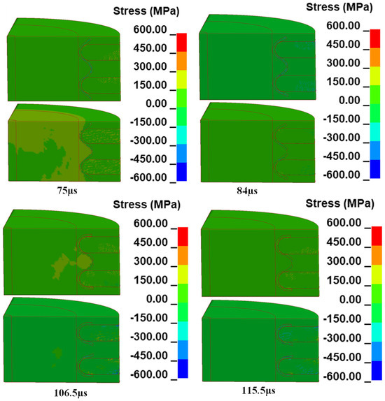
Figure 5.
Fracture process of V-notch (top) and R-notch (bottom) contacts.
Figure 6 presents a comparison of the stress response at the notches of the current contact structures. As shown in the figure, both notch configurations reach their maximum forward compressive stress at 31.49 µs. The V-notch contact exhibits a higher peak compressive stress of 51.44 MPa, compared to 36.99 MPa for the R-notch contact. When the shock wave reaches the outer surface of the copper material, a tensile wave is reflected due to the presence of the free boundary.
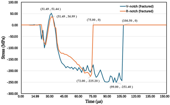
Figure 6.
Stress-time curve at the fracture of current contact.
According to the stress curves, the R-notch contact reaches a maximum tensile stress of 225.20 MPa at 72 µs, while the V-notch contact reaches a higher tensile stress of 251.40 MPa at 99 µs. Following rupture, the internal stress of the contact rapidly drops to zero. As shown in Figure 6, the R-notch contact fractured at 75 µs, while the V-notch contact point failed at 106.5 µs, indicating that the R-notch is more prone to fracture than the V-notch. This result may be attributed to the gentler stress gradient at the root of the R-notch, which tends to form a more uniform stress field. Under the high strain rate of the shock wave, this stress distribution more readily triggers rapid crack propagation. The material cannot release stress through localized plastic deformation, leading to linear crack propagation along the notch root. This results in a short fracture path and minimal energy dissipation.
Analysis of the stress curves indicates that fracture initiation is primarily driven by the reflected tensile wave generated by the initial blast-induced shock wave. Consequently, fracture tends to initiate at the outer surface rather than through direct shear failure from the inner surface.
As shown in Figure 7, the fracture behavior differs significantly between the two notch profiles. The fracture surface of the R-notch exhibits notably greater flatness compared to that of the V-notch. Furthermore, its fracture interface is in complete adhesion with the epoxy grating, whereas a visible gap is present between the fracture surface of the V-notch and the epoxy plane. According to the fracture spacing graph in Figure 7c, the final fracture spacing of the R-notch reaches 0.94 cm, which is 46.9% greater than that of the V-notch (0.64 cm).
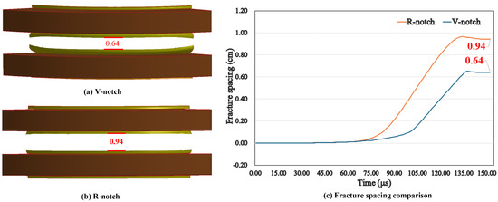
Figure 7.
(a–c) Comparison of current contact fracture spacing.
3. Results and Discussion
Numerical simulation results reveal that the fracture mechanism of the current contact is primarily characterized by a tensile wave-dominated delamination process, with crack propagation evolving from exterior to interior. This contrasts with the conventional shear failure mode, which initiates internally and extends outward. In the V-notch structure, the geometric singularity at the tip causes tensile wave energy to concentrate along the notch’s axis of symmetry, forming a localized region of high tensile stress. This promotes crack initiation at the V-notch tip and propagation along a single, predefined path. Although this generates intense energy localization, the singular crack path limits the overall fracture propagation rate.
In contrast, the flat geometry of the R-notch results in more dispersed tensile wave reflections, generating multidirectional stress superposition zones at both ends of the notch. This configuration promotes simultaneous crack initiation at multiple loci, including the ends and the center, which accelerates the fracture process through crack interaction and coalescence. Consequently, a wider fracture morphology is produced.
Despite the stronger localized stress observed in the V-notch (as shown in Figure 6), it demonstrates both prolonged fracture time and increased span compared to the R-notch. This counterintuitive observation highlights the efficiency of the R-notch’s multi-crack propagation mechanism, which surmounts the limitations associated with single-path fracture and accelerates fracture process. These findings establish a robust theoretical framework for enhancing the interruption performance of the pyro-breaker.
To verify the results of the numerical analyses, explosion breakage tests were conducted on the exploding switch for both current contact configurations. The test setup is shown in Figure 8. The current contact consists of a thin-walled cylinder, filled with deionized water, with the explosive placed at the center of the cylinder and surrounded by four epoxy grids. In both comparative experiments, the explosive charges and simulated models were designed to uniform specifications, specifically as slender cylindrical structures with a radius of 0.5 cm and a height of 8 cm. The sole variable between the two experiments was the difference in the design of the current contact notch structure, while all other experimental conditions were strictly maintained. After the experiments, the spacing of the current contacts under both notch structures was precisely measured using a precision tape measure to quantify the impact of notch design variations on contact separation.
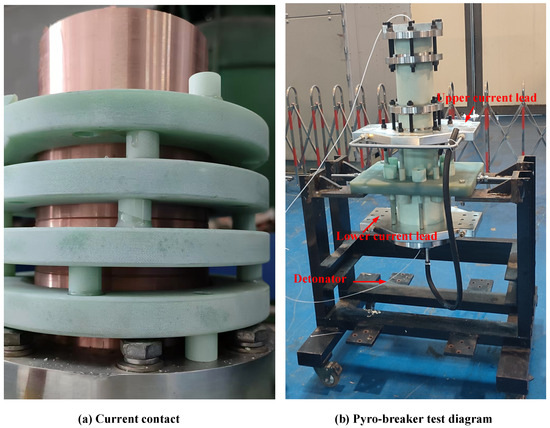
Figure 8.
(a,b) Explosive interruption test of the pyro-breaker.
In this study, effective fracture of the current contact was achieved through the explosive shock wave, as shown in Figure 9, which illustrates the structural and morphological characteristics of the current contact in the pyro-breaker after dynamic fracture. Under explosive loading, the current contact undergoes controlled fracture at the prefabricated notch region, driven by the stress concentration effect. The experimental results show that the fracture morphology of current contact well with the numerical simulation results. Specifically, the fracture surface of the R-notch is more completely separated from the epoxy substrate compared to the V-notch, where a noticeable gap exists between the fracture surface and the epoxy substrate.
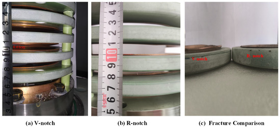
Figure 9.
(a–c) Diagram of current contact fracture results.
The comparative data in Table 3 show that the experimental fracture spacing values for the V-shaped and R-notches are 0.61 cm and 0.90 cm, respectively. These values are within a 5% error margin when compared to the corresponding numerical simulation results of 0.64 cm and 0.94 cm, indicating a high reliability of the numerical analysis model. This high level of agreement not only validates the numerical model’s reliability but also confirms the simulation methodology’s accuracy. The congruence between experimental and simulated data provides robust theoretical support for subsequent pyro-breaker structure optimizations.
Table 3.
Comparison of test pressure and numerical simulation.
4. Conclusions
This study presents a systematic investigation into the cracking mechanisms of the current contact featuring varied notched structures in a pyro-breaker, integrating both numerical simulations and experimental analyses. Key findings are summarized below.
(1) A numerical model was established for water, air, copper, epoxy, and RDX explosives, using a fluid–solid coupling algorithm to simulate the fracture process of V-notch and R-notch current contacts. The simulation results show that the fracture speed of the R-notch increased by 27.3% compared to the V-notch.
(2) Shockwave-driven explosion experiments were designed and conducted. The experimental results indicate that the R-notch design leads to a more thorough fracture of the current contact compared to the original V-notch, with the fracture width increasing by 47.5%.
(3) Through numerical analysis, the fracture mechanism of the current contact under explosive impact loading was identified. The fracture occurs due to the expansion of the tensile wave from the outside to the inside. This provides a theoretical foundation for optimizing the pyro-breaker structure and offers a reference value for other circuit breakers.
Author Contributions
J.Y.: data curation (equal), investigation (equal), methodology (equal), software (equal), validation (equal), and writing—original draft (equal). G.W.: data curation (equal), validation (equal), and visualization (equal). H.L.: formal analysis (equal), methodology (equal), and writing—review & editing (equal). Z.S.: formal analysis (equal) and methodology (equal). project administration (equal) and supervision (equal); P.F.: resources (equal) and supervision (equal). All authors have read and agreed to the published version of the manuscript.
Funding
This work was supported by Comprehensive Research Facility for Fusion Technology Program of China under Contract No. 2018–000052–73–01–001228.
Data Availability Statement
The data supporting the findings of this study are available from the corresponding author upon reasonable request.
Conflicts of Interest
The authors declare no conflicts of interest.
References
- Ongena, J.; Koch, R.; Wolf, R.; Zohm, H. Magnetic-confinement fusion. Nat. Phys. 2016, 12, 398–410. [Google Scholar] [CrossRef]
- Haack, J.; Khatri, B.B. Superconductivity for nuclear fusion: Past, present, and future. Arab. J. Sci. Eng. 2024, 50, 3233–3237. [Google Scholar] [CrossRef]
- Song, Y.T.; Wu, S.T.; Li, J.G.; Wan, B.N.; Wan, Y.X.; Fu, P.; Ye, M.Y.; Zheng, J.X.; Lu, K.; Gao, X.; et al. Concept design of CFETR tokamak machine. IEEE Trans. Plasma Sci. 2014, 42, 503–509. [Google Scholar] [CrossRef]
- Goff, J.; Gascon, J.; Mankani, A.; Song, I. The ITER magnet power supplies and control system. In Proceedings of the 2010 International Conference on Electrical Machines and Systems, Incheon, Republic of Korea, 10–13 October 2010. [Google Scholar]
- Tong, W.; Song, Z.; Fu, P.; Li, H.; Wang, K.; Wang, S.; Zhang, X. Feasibility analysis of 100 kA DC commutation scheme to be applied in the quench protection unit of CFETR. IEEE Trans. Appl. Supercond. 2019, 30, 4700109. [Google Scholar] [CrossRef]
- Tong, W.; Li, H.; Xu, M.; Song, Z.-Q.; Chen, B. Neutron irradiation influence on high-power thyristor device under fusion environment. Nucl. Sci. Tech. 2024, 35, 72. [Google Scholar] [CrossRef]
- Wang, K.; Song, Z.; Fu, P.; Tong, W.; Li, H.; Zhang, X. Structure optimization of fast discharge resistor system for quench protection system. IEEE Access 2019, 7, 52122–52131. [Google Scholar] [CrossRef]
- Xu, M.; Li, H.; Song, Z.; Hu, X.; Tang, C.; Fu, P. The challenge and solution of overvoltage for 100 kA quench protection system in CRAFT project. Fusion Eng. Des. 2022, 175, 113001. [Google Scholar] [CrossRef]
- Fu, P.; Song, Z.Q.; Gao, G.; Tang, L.J.; Wu, Y.B.; Wang, L.S.; Liang, X.Y. Quench protection of the poloidal field superconducting coil system for the EAST tokamak. Nucl. Fusion 2006, 46, S85. [Google Scholar] [CrossRef]
- He, J.; Song, Z.; Tang, C.; Fu, P.; Zhang, J. Designing of cooling water system for a pyro-breaker utilized in superconductive fusion facility. Fusion Eng. Des. 2019, 148, 111294. [Google Scholar] [CrossRef]
- Manzuk, M.; Avanesov, S.; Roshal, A.; Bestuzhev, K.; Nesterenko, A.; Volkov, S. The 70 kA pyrobreaker for ITER magnet back-up protection. Fusion Eng. Des. 2013, 88, 1537–1540. [Google Scholar] [CrossRef]
- Manzuk, M.; Alekseev, D.I.; Krivosheev, S.I.; Magazinov, S.G.; Adamyan, Y.E. Experimental Study of the Deformation Processes of Current-Carrying Elements of Protective Switches for Fusion Application. In Proceedings of the 2021 IEEE Conference of Russian Young Researchers in Electrical and Electronic Engineering (ElConRus), Moscow, Russia, 26–29 January 2021; pp. 1476–1479. [Google Scholar]
- Tang, C.W.; Song, Z.; Li, C.; Wang, Z.; Ye, J.; Li, H.; Fu, P. Computational investigation on the explosively actuated switch utilized in quenching protection system. Fusion Eng. Des. 2021, 163, 112157. [Google Scholar] [CrossRef]
- Tang, C.; Li, H.; Song, Z.; Ye, J.; Xu, M.; Hu, X.; Peng, F. Design and Characterisation of the High-current DC Breaker Driven by Explosive. High Volt. 2022, 8, 466–476. [Google Scholar] [CrossRef]
- Gaio, E.; Maistrello, A.; Barp, M.; Perna, M.; Coffetti, A.; Soso, F.; Novello, L.; Matsukawa, M.; Yamauchi, K. Full scale prototype of the JT-60SA quench protection circuits. Fusion Eng. Des. 2013, 88, 563–567. [Google Scholar] [CrossRef]
- Zhao, H.Z.; Guo, Z.; Zhang, S.; Dan, J.; Liu, M.; Tang, T. Effect of pre-shock on the expanding fracture behavior of 1045 steel cylindrical shell under internal explosive loading. Int. J. Impact Eng. 2025, 196, 105183. [Google Scholar] [CrossRef]
- Mao, W.S.; Zhong, M.; Xie, X.; Ma, H.; Yang, G.; Fan, L. Dynamic response of a hollow cylindrical shell subjected to a near-field underwater explosion. J. Appl. Phys. 2024, 135, 224701. [Google Scholar] [CrossRef]
- Huang, X.P.; Zhu, B.; Chen, Y. A rate-dependent peridynamic–SPH coupling model for damage and failure analysis of concrete dam structures subjected to underwater explosions. Int. J. Impact Eng. 2025, 200, 105270. [Google Scholar] [CrossRef]
- Wang, Y.G.; Liao, C.C.; Wang, J.-H.; Jeng, D.-S. Dynamic response of pipelines with various burial depth due to underwater explosion. Ocean. Eng. 2018, 164, 114–126. [Google Scholar] [CrossRef]
- Liu, M.T.; Ren, G.; Fan, C.; Tang, T.; Wang, X.; Hu, H. Experimental and numerical studies on the expanding fracture behavior of an explosively driven 1045 steel cylinder. Int. J. Impact Eng. 2017, 109, 240–252. [Google Scholar] [CrossRef]
Disclaimer/Publisher’s Note: The statements, opinions and data contained in all publications are solely those of the individual author(s) and contributor(s) and not of MDPI and/or the editor(s). MDPI and/or the editor(s) disclaim responsibility for any injury to people or property resulting from any ideas, methods, instructions or products referred to in the content. |
© 2025 by the authors. Licensee MDPI, Basel, Switzerland. This article is an open access article distributed under the terms and conditions of the Creative Commons Attribution (CC BY) license (https://creativecommons.org/licenses/by/4.0/).