Article

Mechanical Performance Enhancement of Aluminum Single-Lap Adhesive Joints Due to Organized Alumina Nanotubes Layer Formation on the Aluminum Adherends

by
George C. Papanicolaou
1,*,
Lykourgos C. Kontaxis
1,
Diana V. Portan
1,
Grigoris N. Petropoulos
1,
Eleni Valeriou
1 and
Dimitris Alexandropoulos
2
1
Department of Mechanical Engineering and Aeronautics, University of Patras, 265 00 Patras, Greece
2
Department of Materials Science, University of Patras, 265 00 Patras, Greece
*
Author to whom correspondence should be addressed.
Appl. Nano 2021, 2(3), 206-221; https://doi.org/10.3390/applnano2030015
Submission received: 8 June 2021 / Revised: 19 July 2021 / Accepted: 28 July 2021 / Published: 3 August 2021
(This article belongs to the Collection Feature Papers for Applied Nano)

Abstract

:
The present investigation aims to take a step forward for the transfer of a simple laboratory electrochemical method of surface nano-treatment of aluminum to industrial applications. The electrochemical method has been applied to process 1050A aluminum. Surface nano-structuring has been achieved and resulted in the formation of an organized alumina nanotubes layer on commercial aluminum plates used as adherends for the manufacturing of aluminum single-lap adhesive joints. The mechanical properties of single-lap aluminum adhesive joints constructed with both non-anodized and anodized adherends were investigated and compared. Two types of epoxy resins were used to prove that the anodization of the adherends is equally effective, independently of the adhesives’ type. Furthermore, three overlap lengths were used (7, 10, and 25 mm) to study the effect of the overlap length on the overall joint mechanical response. Results of both three-point bending and tensile–shear testing showed that there is a considerable improvement of the joints’ mechanical performance with the addition of the nanostructures, for all the overlap lengths. It was found that the anodization method greatly contributes to the strengthening of the joints, leading to a strength increase of up to 176% and 148% for the shear and three-point bending strength, respectively.

1. Introduction

The advances in fabrication technologies associated to a wide range of novel available nanomaterials allow for the improvement of systems across a wide spectrum of applications. Several studies on nano-enabled multifunctional materials report research breakthroughs related to the improvement of both functional and structural properties for space and aircraft applications with the addition of nanostructures and hierarchical structures [1]. The addition of nanophases in the material structure has been proved to be a gain in terms of mechanical output. On the other hand, the introduction of a nanophase requires precision with regards to its optimum content and the ideal combination with other materials that will result in the formation of a robust and mechanically stable structure. The optimization of the control parameters of such processing routes is highly desired in order to develop novel multifunctional materials.
In view of their excellent strength and lightweight properties, aluminum and its alloys have led to widespread aerospace and non-aerospace applications, due to good corrosion resistance and other outstanding properties [2,3]. Particularly, the joining of aluminum alloys has prospect requests in aircraft, automobile, and marine manufacturing that could decrease weight and cost and increase mechanical and thermal properties [4,5]. The adhesive bonding of components represents a major asset and a very good alternative to traditional mechanical assembly techniques, such as bolting and welding. Adhesive bonding offers a more uniform distribution of stress, can join small components, can prevent or reduce the corrosion between dissimilar materials, and does not require holes that can introduce cracks in the structure [6]. The characteristics of an adhesively bonded joint depend on the material’s nature, the adhesion of the parts and cohesion of the adhesive, and the wetting behavior of the adherend surface and the adhesive, as well as on other phenomena developed in the bonding area.
The region adjacent to the interface between the substrate and the polymeric adhesive is the key point in improving the overall properties of the joint. Debonding is always interfacial or close to the interface, and directly related to the interphase structure. The role of weak boundary layers in determining the breaking stress of adhesive joints has been proposed to be that of a discrete surface layer of material with strength properties inferior to the bulk material from which it originated. The breaking strength behavior of various polyethylene-epoxy adhesive lap joints has been used as evidence for the presence or absence of weak boundary layers [7]. The sensitivity of adhesive joints toward stresses and humidity is a puzzling problem that can be solved by applying surface processing methods on adherends. Smart coatings have been lately developed to protect the metal substrates from corrosion or other mechanical and physical damages [8]. Such superhydrophobic coatings are intensively investigated for various applications in automotive, marine, medical, and energy sectors. Common fabrication techniques are identified as the sol–gel, wet chemical, and electrochemical deposition, and mussel-inspired chemistry [9]. Treatments such as anodizing, etching, or the use of primers modify the metal surface energy or chemistry, thereby promoting physical and chemical interaction [10]. The idea of electrochemically processing the metallic adherends through different methods dates back to the 1980s [11]. In the construction of joints, it has been proved that the ionic etching of the metal–epoxy joint shaped a fine structure inside the polymeric interface that comprised a dense network of columns originating from the aluminum layer and extending over a length of 5 μm [12]. The electrochemical processing of the adherend surface has been reported as efficient and, moreover, crucial for improving joint performance. It has recently been found that metal anodization followed by vibratory shot peening leads to an increased strength of metallic adhesive joints, irrespective of the type of applied epoxy adhesive [13]. Moreover, it has been stated that the bond strength depends on many surface characteristics, such as the peak density, nano-scale pores, and texture direction, instead of only the roughness value or wettability, while the shear energy consumption of the single-lap joints is positively correlated with the shear strength, which in turn depends on the surface treatment methods. Surface pre-treatment to a bonded substrate can remove surface contaminants, control surface topography, and improve surface wetting characteristics, thereby increasing the mechanical interlocking or chemical bonding between the adhesive and the substrate [14].
The electrochemical anodization is a simple, cost-effective processing method of surfaces that allows the formation of highly organized nanostructures (i.e., oxide nanotubes) and the functionalization of metallic surfaces for specific applications [15,16,17]. However, some issues, such as (i) the lack of processability of various sample sizes and geometries and (ii) the need to find a different anodization recipe for each metal, exist. Generally, research on the electrochemical anodization of metals is conducted on standard plates provided by well-known suppliers [18,19,20]. Anyhow, most of the metals that are used in the industrial sectors, such as aeronautics, shipbuilding, and automotive, are low-cost and alloyed; this is because the low-cost metals allow the acquisition of large parts. In the laboratory research, results are influenced by very small changes in the metal’s structure and composition (i.e., alloying or impurities). Thus, small differences in the metal’s structure (purity, density, and porosity) modify the anodization results. This makes it difficult to realize the transfer of the process from the lab to the industries/market [21]. Investigations are required to manage the shifting of the new nano-functionalized joints to applications, which is the purpose of the present study. Efforts in this direction have already been made by some research teams [22].
The present investigation aimed to improve the mechanical performance of aluminum adhesive joints, since these are highly demanded in several industrial and commercial sectors. The electrochemical anodization method has been applied in order to enable the surface processing of industrial grade low-cost aluminum. Surface nano-structuring has been achieved and resulted in the formation of alumina nanotubes on the industrial grade metal. The anodized parts were used in the construction of aluminum adhesive joints. The purpose of the nano-functionalization was to improve the adhesion strength and the overall mechanical performance of this type of structure, by modifying the interphase region created in the joining area.

2. Materials and Methods

2.1. Materials

Low-cost aluminum A1050 of 99.6% purity was purchased by Manousaridis Bros OE (Athens, Greece). The epoxy resin system used as adhesive material for the single-lap joints was a resin type Araldite LY 1564 (bisphenol A) combined with Aradur 2954 (cycloaliphatic polyamine) as curing agent at a ratio 100:35 parts by weight. The curing time was of 1 h at 80 °C followed by 8 h at 140 °C. A second, preliminary study was performed with a different epoxy resin to observe whether the adhesive type affects the influence of anodization on the mechanical behavior of the joints. The second epoxy resin applied was RenLam CY219 (bisphenol A) combined with Ren HY 5161 (diamine) as curing agent at a ratio 2:1 by weight and a curing temperature of 50 °C for 24 h. The properties of the two resins used can be seen in Table 1.

2.2. Electrochemical Anodization of the Adherends

The electrochemical anodization method has been applied in order to manufacture an alumina nanotubes layer on the aluminum plates surface. The aim was to increase the surface roughness of the adherends and to expand the contact area with the adhesive, as well as to obtain a stronger interlock at the interphase between adherends and adhesive. The metallic plate was mounted as an anode and a graphite bar was used as a cathode. The anodization was performed only in the joining region of the aluminum adherend. The distance between the electrodes was 2.5–3 cm. Three main anodization parameters influenced the results: (i) the electrolyte type, (ii) the anodization duration, and (iii) the applied voltage. Several combinations of these parameters were tested in order to obtain the optimized recipe for the formation of organized alumina nanotubes. The optimum one is given in Table 2.
Before and after anodization, specimens were polished with sandpaper, starting from 320 grits for few seconds, followed by polishing with an intermediate sandpaper of 600 grits for 2 min, and ending with 5 min methanol (5 min) before and after each anodization step and then dried at room temperature. At the end of the anodization, aluminum specimens were ultrasonicated in 3 wt% H3PO4, for three minutes. Finally, specimens were left to dry at room temperature.

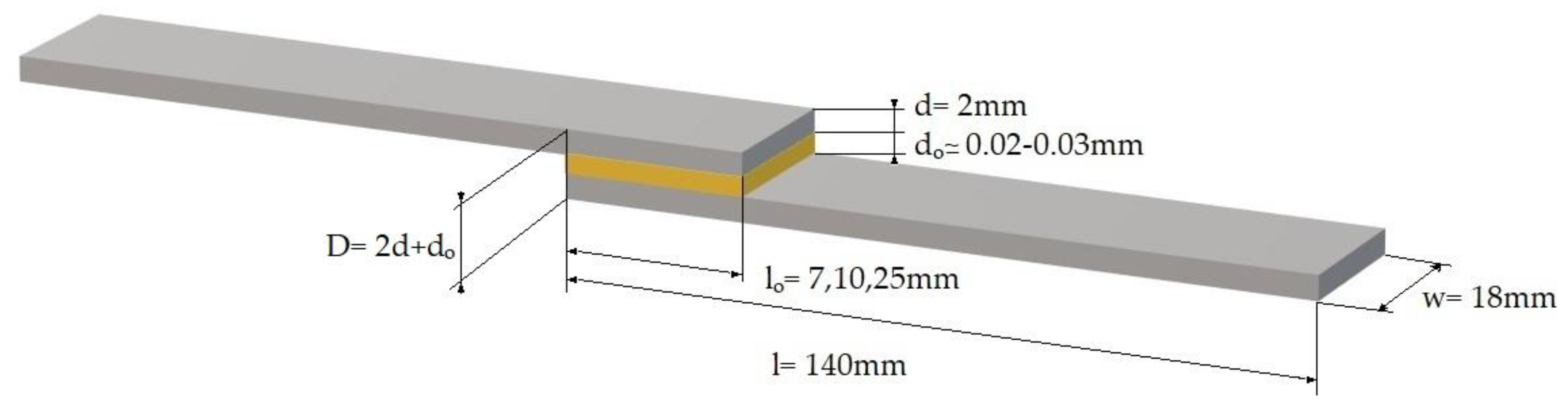
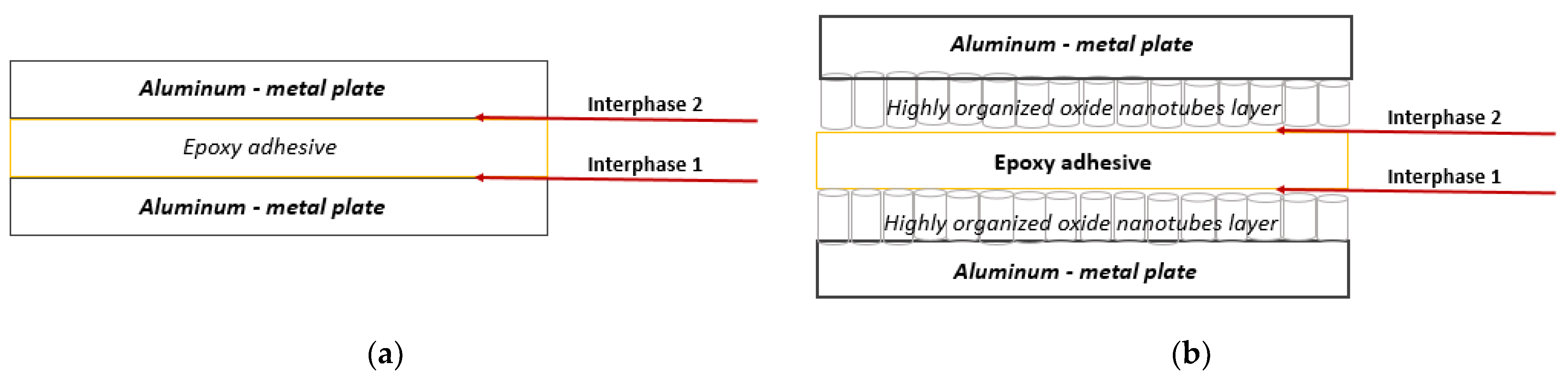
2.3. Manufacturing of the Joints

Aluminum adherends had dimensions of 140 × 18 × 2 mm, as shown in Figure 1, and were cut from a larger sheet using laser cutting technique. Adhesive joints made of non-anodized and anodized adherends were manufactured. The overlap lengths were 7, 10, and 25 mm, according to ASTM D1002-01. The epoxy resin/hardener system was placed in a vacuum chamber for 10 to 15 min to remove air bubbles. The epoxy adhesive was uniformly applied in a thin layer (approx. 20–30 μm) on one adherend surface and subsequently bonded to the second adherend under controlled pressure at room temperature conditions. Finally, the specimens were placed in an oven for the epoxy resin to cure. The curing profiles of the epoxy resins used were given above in chapter Section 2.1.
Two different types of single-lap adhesive joints were manufactured:
  • Aluminum/neat epoxy resin/aluminum (reference joint);
  • Anodized aluminum/neat epoxy resin/anodized aluminum.
Finally, the joining region is composed of several interphases, as shown in Figure 2. For the reference joints (Figure 2a), the overlap area includes two interphases formed by the two aluminum plates, in contact with the adhesive. For the electrochemically processed metallic adherends, the interphase of the overlap region includes the metallic substrate, the alumina nanotubes layer formed on its surface, and the adhesive, as schemed in Figure 2b. Nanotubes are shaped during the electrochemical anodization in a very thin nanometer scale layer on the surface of the metallic plate. It is expected that this nanotubes layer builds up a more robust and complex interphase structure.

2.4. Surface Analysis and Mechanical Characterization

A SEM device, Model Zeiss SUPRA 35VP was used to observe specimens’ micro/nanostructure.
The apparent shear strength of the adhesive was determined through tensile loading of the joint, as indicated by ASTM D1002-01, using an Instron 4301 (High Wycombe, UK) universal mechanical testing machine. The adhesive shear strength τ was calculated as the maximum shear stress achieved in an adhesive layer, based on recorded maximum tensile forces for each tested joint as given by Equation (1).
τ = P w l o .
where τ is the adhesive shear strength, P is the load, w is the width, and lo is the overlap length.
In all cases, a constant crosshead speed of 1 mm/min was applied. The experimental setup is shown in Figure 3a,b. Five or more specimens per type (i.e., anodized and non-anodized) were tested to ensure the repeatability of results.
Next, single-lap joint specimens underwent a series of quasistatic three-point bending using an Instron 4301 (High Wycombe, UK) universal mechanical testing machine. The tests were performed at room temperature to investigate the overall flexural behavior of the adhesive single-lap joints. Flexural stress and strain values were calculated according to Equations (2) and (3), respectively.
σ = 3 F o r c e L s 2 w D 2 ,
and   ε = 6 d i s p l a c e m e n t D L s ,
where σ is the flexural strength, Ls is the span length, w is the width, and D is the single joints depth as shown in Figure 1. In all cases, a constant crosshead speed of 1 mm/min was applied. All specimens had a total length of 230–266 mm and a constant span length of 100 mm. The experimental setup used is shown in Figure 3c. Five or more specimens per type (i.e., anodized and non-anodized) were tested to ensure the repeatability of results.

3. Results and Discussion

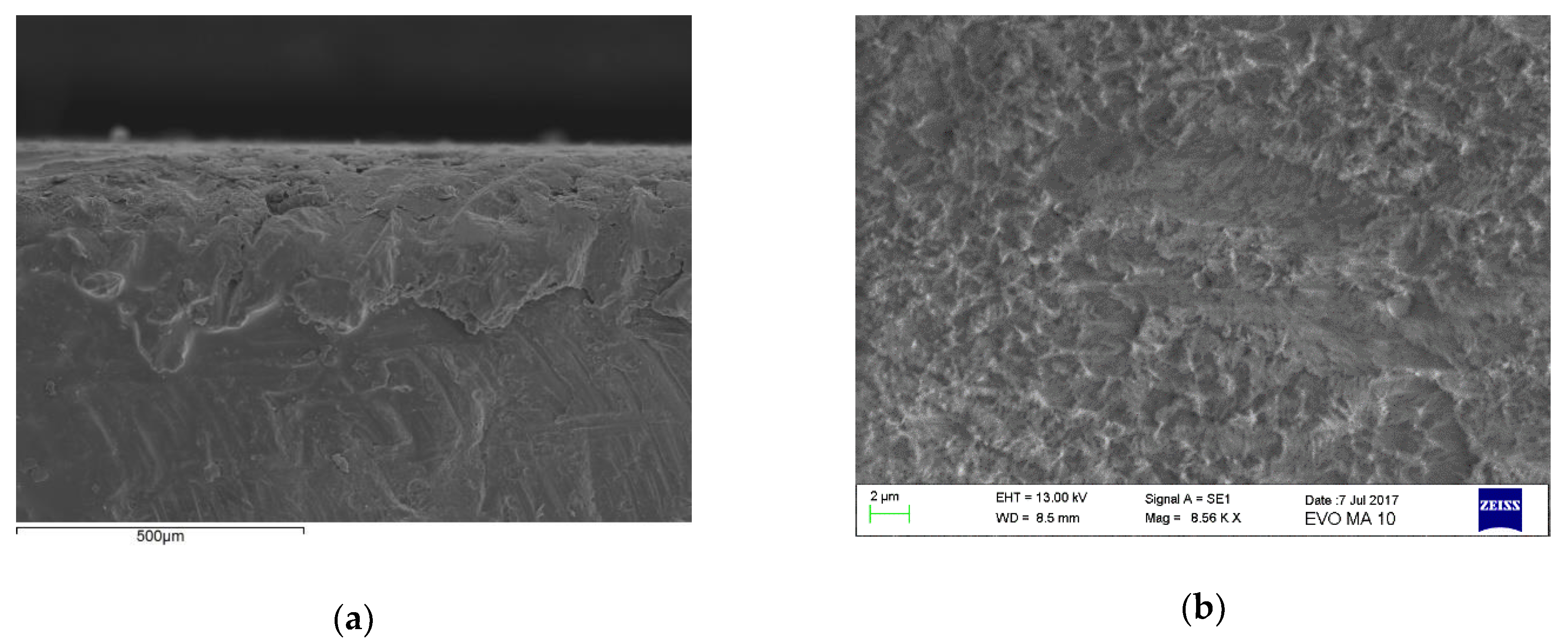
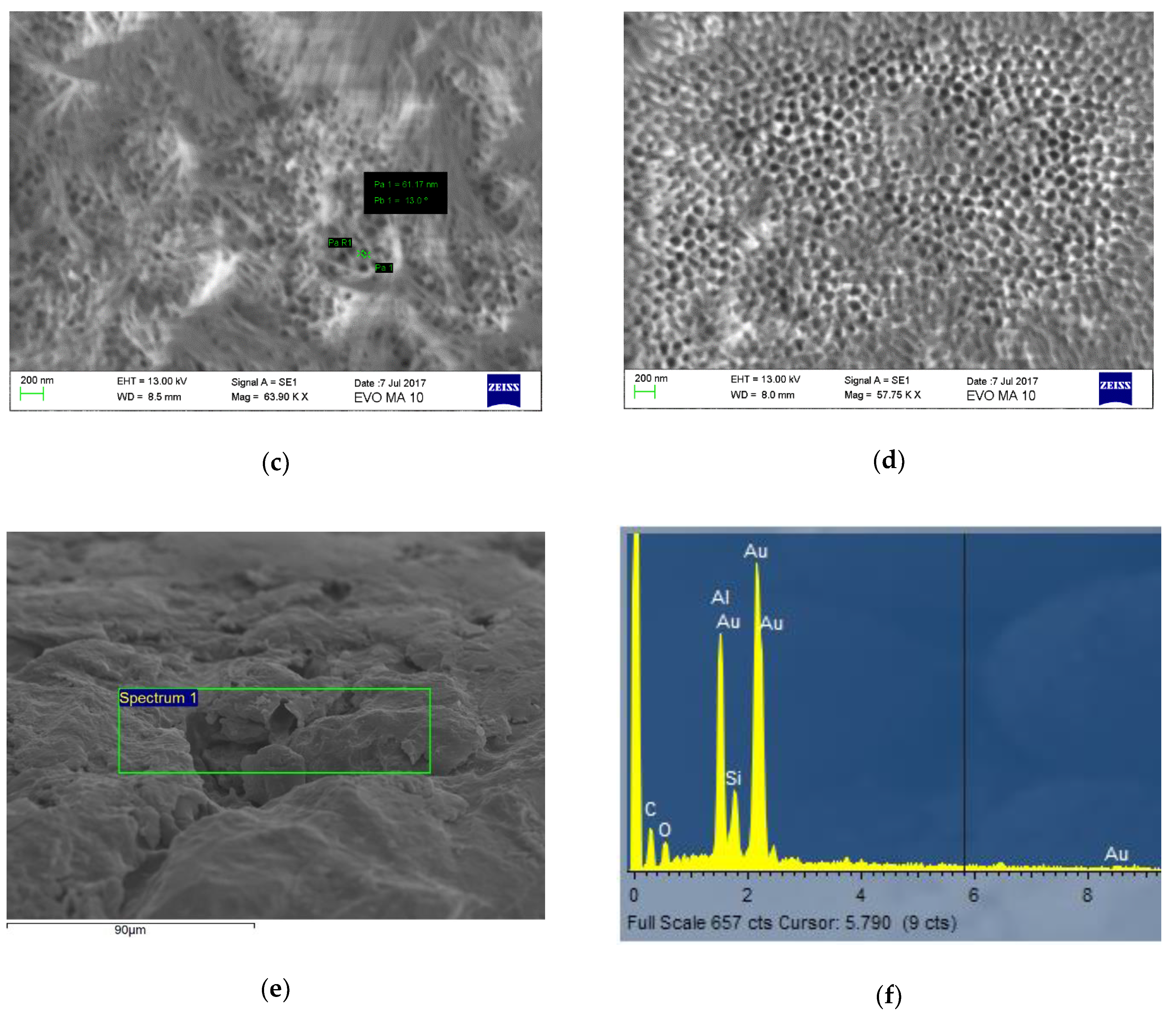
3.1. Anodization Results

A new recipe that enables the formation of alumina nanotubes on commercial aluminum plates was found. The anodization protocol within the present investigation emerged after many trial and error experiments and after combining several literature-recommended recipes [23,24,25,26].
By applying the above-mentioned protocol of hard anodization, an alumina nanotubes layer (Figure 4d) was shaped on the aluminum plates. The surface topography of the substrate after the several anodization steps of the protocol may be seen in Figure 4a–c. Nanotubes cannot be seen clearly prior to ultrasonication (Figure 4c). The pore widening and the elimination of chemical traces from the electrolyte was achieved by applying this step of ultrasonication in 3 wt% H3PO4. As observed, nanotubes with a diameter between 50–60 nm formed over the entire analyzed surface. The diameters of the nanotubes can be adjusted by changing the anodizing parameters. The elemental analyses of the sample showed that the aluminum was industrial grade, and alloying elements were present; also, epoxy resin traces were found on the surface of the joining area (Figure 4f).
The anodization of metallic plates involves some standard steps, which are crucial for the formation of highly organized nanostructures. These steps are:
  • The finishing of the surface before anodizing, which is necessary since it reduces discontinuities and creates a flat and smooth surface for the formation of self-organized nanotubes within the oxide layer;
  • The cleaning step with methanol/ethanol, which reduces existing impurities on the sample surface;
  • The ultrasonication, which is performed to remove the upper part of the nanotubes layer in order to create a large opening, as well as to remove traces of chemical elements deposited from the electrolyte.
In the case of aluminum anodization, specific steps of the protocol have a well-defined role in the formation of highly organized alumina nanotubes on the metallic plates:
  • Electropolishing: a 3 wt% HF aqueous electrolyte is used for the electropolishing. This process is exothermic; in order to avoid accidents caused by high temperatures, the electrolyte was frozen and then partially melted before the experiment. This helped to maintain a low temperature during the experiment. The hydrofluoric electrolyte is a passivating agent which enables the formation of the oxide layer, followed by the formation of pits. The selected electric potential (20 V) was found appropriate since it allows the formation of a thick oxide layer where pits are homogeneously distributed on the aluminum surface. A higher electric potential would lead to the formation of deep cavities instead of uniformly shaped pores, which are not suitable for the pre-formation of alumina nanotubes. A lower potential assures safe conditions to run the experiment and appropriate ones for a guided anodization and build-up of initial pores;
  • Pre-anodization: The first anodization step, called pre-anodizing, allows a field-assisted dissolution of the oxide under a higher electric potential (40 V) compared to the previous step of electropolishing. This process is referred to as the field-assisted emission of aluminum ions and is considered a prerequisite for the controlled formation of a porous alumina oxide [27];
  • Anodization: The second anodizing step is performed for an extended time (4 h) compared to the pre-anodization, and runs at a higher voltage (60 V), thus enabling a guided self-building of the nanotube architecture.
In order to obtain the expected result, which is the alumina nanotubes layer on the commercial aluminum, a gradual increase of the electric potential is required, from 20 to 60 V; hard anodizing in acid-based electrolytes has been used. Mild anodizing is proposed in the literature, since it has been affirmed that it leads to more organized layers of nanotubes. Mild anodization has satisfactory results in the case of pure aluminum, with well-defined characteristics and highly polished surfaces [28], to be used in the construction of micro-devices. The purpose of the present investigation was to obtain the oxide nanotubes on low-cost commercial aluminum, which can be further used in industrial applications that involve the manufacturing of big structural parts. This type of aluminum has larger initial pores in its structure, as well as discontinuities and some alloying elements, when compared to the highly pure aluminum, and this makes the mild anodization inefficient. In this case, hard anodization is the only option.
A description of the synthesis process of the alumina nanotubes has been made by Lee et al. [29]. It has been reported that this process is related to the evolution of oxygen gas bubbles from the anode surface during the hard anodizing of aluminum. The growth rate of anode oxide membranes in hard anodizing processes decreases with anodizing time. The formation mechanism of the nanotubes and their array has been previously discussed based on the evolution of voids in the porous alumina membrane. With the thickening of the alumina film, voids begin to grow, resulting in grain boundaries. When a pulse voltage is applied to the porous alumina membrane, the tensile stress changes abruptly and splits the junctions between the voids, thus leading to the interlaced cleavages of the cells. As a result, the nanotubes and their array are formed [30].

3.2. Mechanical Evaluation

In an adhesively bonded joint, three major modes of failure exist. The first two are a cohesive failure within the adhesive layer, which corresponds to the ultimate strength of the adhesive itself, and an adhesive failure when the adherence between the adhesive and the substrate is weaker than the cohesive strength of the adhesive. The third one is a cohesive failure within the substrate itself, and is very unusual when the substrate is metallic [31]. Within the present investigation, the structure of the overlap region has been modified through the introduction of nanotubes perpendicular to the substrate (adherend), which are parallel to each other and create an increased surface area between the two surfaces in contact. The ‘brash’ structure of the nanotubes increases the contact area, and it is expected that the nanotubes create better interlocking conditions while strengthening the adhesion mechanism. The focus is, in this case, on the failure in joints with non-anodized vs. anodized adherends when under different mechanical loading.

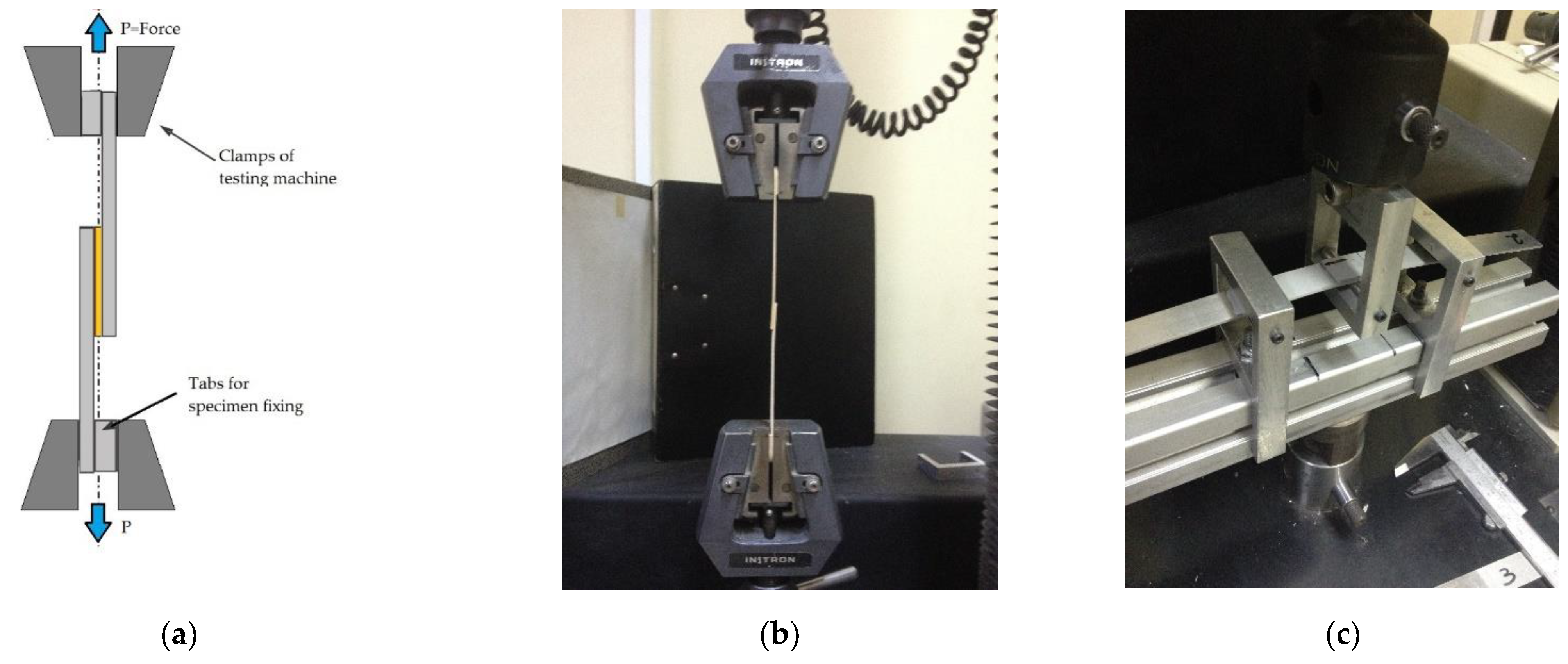
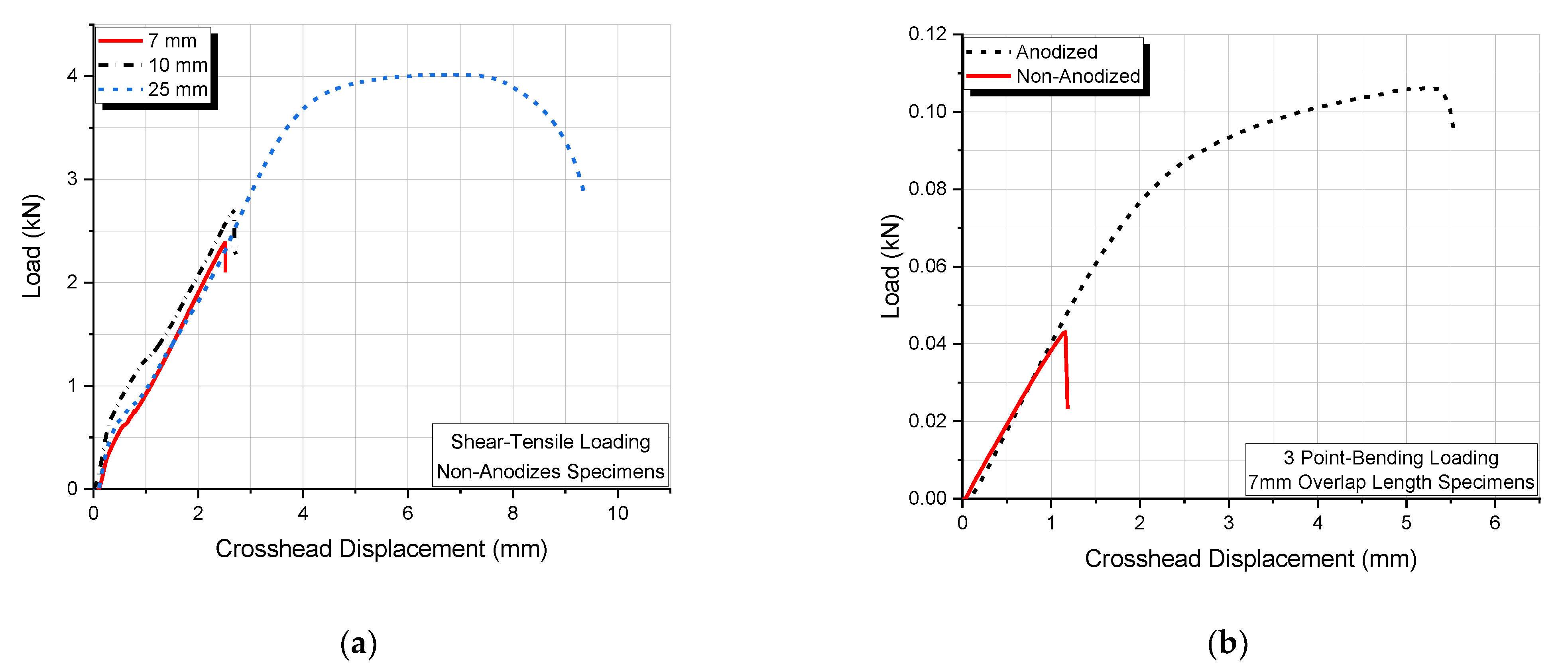
3.2.1. Shear Strength by Tensile Loading

Polymeric adhesives used for joining applications usually exhibit linear/non-linear viscoelastic/viscoplastic behavior depending on the loading and temperature conditions. This time-dependent adhesive behavior results in stress and strain redistribution in the overlap area, which in turn affects the joint strength. In the case of viscoelastic behavior, the response of the material to an external mechanical excitation is time and temperature-dependent. Thus, in plastics whose behavior is primarily viscoelastic, it is observed that their stiffness, strength, and ductility, as well as other properties, are sensitive to several parameters, such as:
  • Strain rate;
  • Loading rate;
  • Deformation or loading history;
  • Temperature;
  • Heating or cooling rate;
  • Humidity, etc.
Polymers, even under normal environmental conditions, show strong viscoelastic behavior. In contrast, in metals, the viscoelastic behavior occurs at higher temperatures.
Let us consider the single-lap test shown in Figure 5. The specimen consists of two rectangular adherends, bonded together, with an overlap length ranging from 7 to 25 mm. End tabs, cut from the same material as the adherend sections, are adhesively bonded to the specimen to reduce the eccentricity of the load path that causes out-of-plane bending moments and, consequently, high peel stresses and non-uniform shear stresses in the adhesive layer. The long axis of the specimen coincides with the direction of the applied force P through the center line of the grip assembly. The load P is applied to the rigid adhesive substrate in a direction parallel to the shear. If the overlap area is denoted as A, the adhesive thickness as h, and the displacement as x, then the mean shear stress σ is expressed as
σ = P A .
We can observe that for a constant specimen width, the greater the overlap length, the larger the cross-sectional area A and therefore the smaller the average shear stress that develops in the adhesive. Next, the mean shear strain is expressed as
ε = x d o .
If the applied displacement-rate has a constant value v, then
v = d x d t .
Combining Equations (5) and (6), the following equation is obtained
d ε d t = v d o .
Next, it is assumed that the adhesive linear viscoelastic behavior is represented by the simple Voigt model shown in Figure 6a. The model exhibits an iso-strain behavior. Thus, the Voigt model constitutive equation is
σ = G ε + η d ε d t
from which
σ = G ε + η d ε d t = G ε + η v d o = G ( ε + τ v d o )
where
τ = η G
is the relaxation time.
Next, it is assumed that the adhesive linear viscoelastic behavior is represented by the simple Maxwell model as shown in Figure 6b. The model exhibits iso-stress behavior. Thus, the Maxwell model constitutive equation is
G d ε d t = d σ d t + σ τ .
Solving Equation (11) for the stress, we find that
σ = η v d o [ 1 exp ( ε G d o η v ) ] = G τ v d o [ 1 exp ( ε d o τ v ) ] .
If, for both models, it is assumed that adhesive bond failure takes place when the strain ε attains a critical value εc, then if σb denotes the adhesive bond strength, we can write for the Voigt model:
σ b = G ε c + η v d o = G ( ε c + τ v d o ) .
and similarly, for the Maxwell model:
σ b = η v d o [ 1 exp ( ε c G d o η v ) ] = G τ v d o [ 1 exp ( ε c d o τ v ) ] .
In both models, the bonding strength σb increases as the displacement rate v, shear modulus G, and viscosity η and/or relaxation time τ increase, and as the adhesive layer thickness d0 and overlap length lo decrease. These observations well explain the observed decrease in shear strength with increasing overlap length, as shown in Figure 7.
As for the differences in shear strength observed in the same Figure when comparing non-anodized specimens with the respective anodized ones, it can be stated that surface modification, by formation of alumina nanotubes arrays, improves the adhesive bond strength through contributions from mechanical and chemical bonding. Surface modification of aluminum plates by electrochemical anodization enhances the bonding characteristics in many ways. Overall, the surface area increases due to the formation of alumina nanotube arrays. The oxidation also generates micro-pores and contributes to improving mechanical bond strength by providing submicron-sized locking sites for the adhesive. The increased contact area also contributes to the enhanced bond strength. The increase in bond strength in anodized specimens above that of non-anodized possibly arises due to the formation of a composite structure at the bond interface.
Analyzing Figure 7a, we may observe that all joints that were manufactured with anodized adherends in the case of the Araldite adhesive presented improved strength when compared with non-anodized ones, regardless of the overlap length. Specifically, the largest increase in the shear strength was observed in the specimens with an overlap length of 7 mm (175.9%). Subsequently, the 10 mm and 25 mm overlap lengths showed an almost similar increase in the shear strength of 80.9% and 80.6%, respectively.
In Figure 7b, we can see that for joints with the RenLam adhesive, there was also an 80.1% increase in the shear strength with the addition of the nanotubes in the adherend structure.
The above results can also be verified by the load–displacement curves shown in Figure 8. More precisely, the effect of overlap length on the tensile–shear load for non-anodized joints, as well as the effect of anodization versus non-anodization of single-lap joints loaded in a three-point bending mode, are shown.

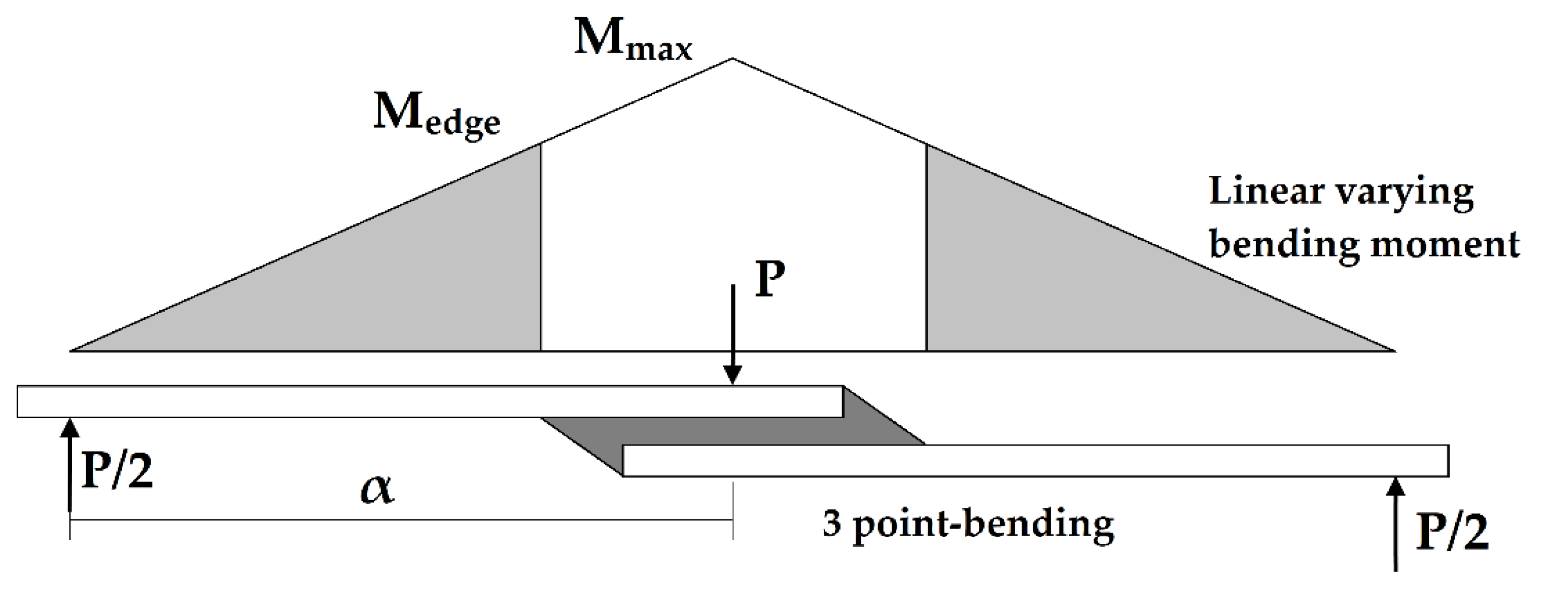
3.2.2. Three-Point Bending of Joints with Araldite Adhesive

Since single-lap joints, when in service, may be loaded under tension or bending conditions and/or under more complex modes, it is important to additionally study the joint behavior under three-point bending loading. Another reason for studying the bending behavior of joints is that this type of joint loading is not well documented as tensile–shear loading.
If the adhesive thickness is kept at 0.02 mm, and the joint width at 18 mm, the effect of increasing the overlap length is to increase the maximum load that can be taken by the joint before the crack initiates, as shown in Table 3. Since the bending moment in the three-point bending test varies linearly from zero to Mmax at the midpoint of the overlap length (see Figure 9), an increase in said overlap length would effectively reduce the bending moment at the edge of the overlap where failure initiates. The moment at the edge of the overlap (Medge) can be expressed in terms of the maximum moment (Mmax) at the center of the joint, the distance between the inner and outer supports (α), and the overlap length (lo):
M e d g e = P 2 ( α l o 2 ) ,
and since
M m a x = P 2 α ,
then
M e d g e = M m a x ( α l o 2 ) 1 α .
The cumulated values of the mechanical properties of the aluminum adhesive joints resulting in both tensile–shear loading and three-point bending can be seen in Table 3.
As observed in Figure 10, a significant increase in the flexural strength of the joints exists in the case of joints that were manufactured with anodized adherend parts, for both Araldite and RenLam adhesives.
In Figure 10a, we can observe an increase in flexural strength with overlap length for both anodized and non-anodized specimens, with the anodized specimens always showing a higher strength compared to the respective strength of non-anodized joints. In addition, from the same figure, we can observe that the rate of strength increase with overlap length for the non-anodized joints is higher than the respective rate for anodized joints. Finally, the flexural strength of anodized joints is kept at quite high levels, with a small variation of the strength value. The latter means that the effect of anodization on the flexural strength dominates the flexural behavior of the joints, being much stronger than the respective effect of the overlap length. The same behavior is observed for the second adhesive used.

4. Conclusions

From the present investigation, the following main conclusions were drawn:
  • A new recipe for the anodization of commercial aluminum for industrial applications has been proposed, with the purpose to nano-functionalize the metal’s surface. Through this method, a nanometer scale layer of alumina nanotubes has been formed in the upper part of the aluminum. Given that very few works were dedicated to the nano structuring of low-cost aluminum, it is considered that the anodization recipe can find immediate application in industries (aeronautics, maritime, automotive etc.);
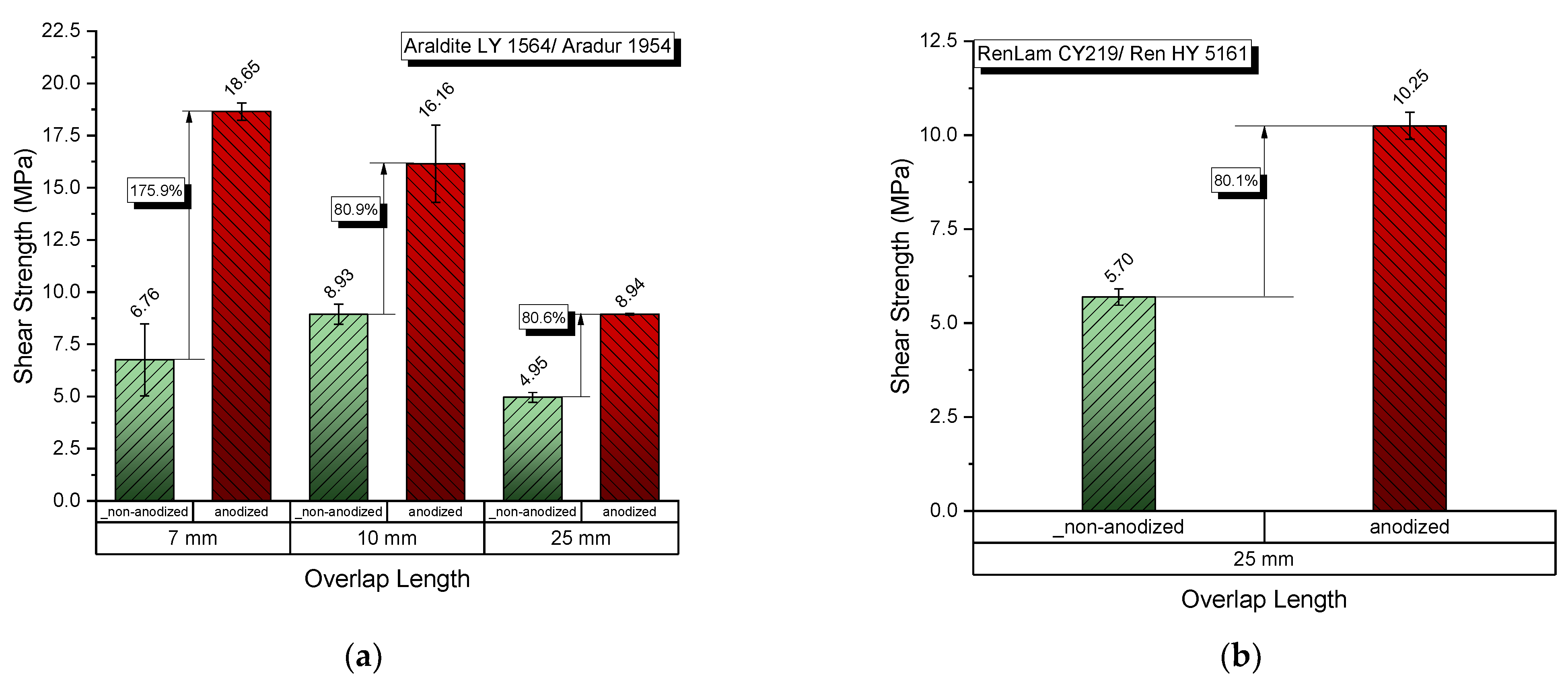
  • A general conclusion of all of the aspects studied in the present investigation is that anodization of aluminum substrates led to tremendous increases in both tensile–shear strength (175.9%) and overall bending strength (148.4%), irrespectively of the adhesive type used.
Results obtained from the tensile–shear experiments led to the following conclusions:
  • Concerning the tensile–shear loading, all joints with anodized adherends showed values of maximum load that were much higher than the corresponding joints with non-anodized adherends, regardless of the overlap length. The most evident increase was observed in joints with 7 mm overlap length, where the experimental results for the tensile–shear strength presented above indicate that the joints with an overlap length of 7 mm had the greatest strength increase (Figure 7a), while the joints with 10 and 25 mm overlap lengths had almost the same percentage (~80%) increase in the maximum load compared to the joints with non-anodized adherends with the same overlap length;
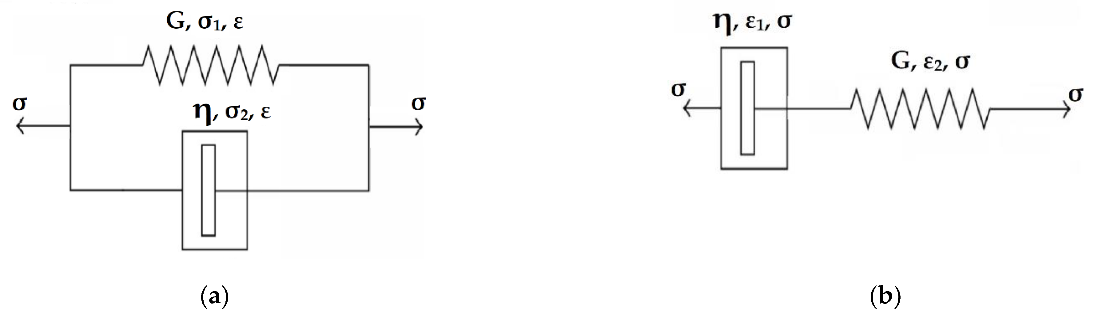
  • The above results were qualitatively verified by applying simple linear viscoelastic models.
In addition, results obtained from three-point bending experiments led to the following conclusions:
  • All joints with anodized adherends showed improved strength when compared to those with non-anodized adherends, regardless of the overlap length (Figure 10). The most significant flexural strength improvement due to nano-functionalization of the adherends was 148.4%, and was observed in specimens with a 7 mm overlap length;
  • The nano-functionalization of adherends proved efficient even when the epoxy adhesive was changed. A preliminary study of joints with a 25 mm overlap length, for which RenLam adhesive was used, showed a 151.6% enhancement in flexural strength with the addition of the nanotubes layer to the adherends (Figure 10b);
  • The above results were qualitatively verified by applying the classical three-point bending theory.

Author Contributions

Data curation, G.N.P. and E.V.; Formal analysis, L.C.K.; Investigation, G.N.P.; Software, L.C.K. and D.A.; Validation, L.C.K. and D.A.; Visualization, G.C.P.; Writing—original draft, D.V.P.; Writing—review & editing, G.C.P. All authors have read and agreed to the published version of the manuscript.

Funding

This research received no external funding.

Institutional Review Board Statement

Not applicable.

Informed Consent Statement

Not applicable.

Conflicts of Interest

The authors declare no conflict of interest.

References

  1. Balasubramanian, K.; Tirumali, M.; Badhe, Y.; Mahajan, Y. Nano-enabled Multifunctional Materials for Aerospace Applications. In Aerospace Materials and Material Technologies; Springer: Singapore, 2017; pp. 439–453. [Google Scholar]
  2. Daniyan, I.A.; Tlhabadira, I.; Mpofu, K.; Adeodu, A.O. Process design and optimization for the milling operation of aluminum alloy (AA6063 T6). Mater. Today Proc. 2021, 38, 536–543. [Google Scholar] [CrossRef]
  3. Xie, D.; Li, W. A novel simple approach to preparation of superhydrophobic surfaces of aluminum alloys. Appl. Surf. Sci. 2011, 258, 1004–1007. [Google Scholar] [CrossRef]
  4. Shehabeldeen, T.A.; Yin, Y.; Ji, X.; Shen, X.; Zhang, Z.; Zhou, J. Investigation of the microstructure, mechanical properties and fracture mechanisms of dissimilar friction stir welded aluminium/titanium joints. J. Mater. Res. Technol. 2021, 11, 507–518. [Google Scholar] [CrossRef]
  5. Marchione, F. Stress distribution in double-lap adhesive joints: Effect of adherend reinforcement layer. Int. J. Adhes. Adhes. 2021, 105, 102780. [Google Scholar] [CrossRef]
  6. Ciardiello, R.; Greco, L.; Miranda, M.; Di Sciullo, F.; Goglio, L. Experimental investigation on adhesively bonded U-shaped metallic joints using the Arcan test. J. Adv. Join. Process. 2020, 1, 100010. [Google Scholar] [CrossRef]
  7. Sharpe, L.H. The lnterphase in Adhesion. J. Adhes. 1972, 4, 51–64. [Google Scholar] [CrossRef]
  8. Salam, A.; Makhlouf, H.; Prado, J. Chapter 2: Recent developments in smart coatings for steel alloys, their impact in the steel industry, and applications. In Advances in Smart Coatings and Thin Films for Future Industrial and Biomedical Engineering Applications; Salam, A., Makhlouf, H., Abu-Thabit, N.Y., Eds.; Elsevier: Amsterdam, The Netherlands, 2020; pp. 39–55. [Google Scholar]
  9. Hooda, A.; Goyat, M.S.; Pandey, J.K.; Kumar, A.; Gupta, R. A review on fundamentals, constraints and fabrication techniques of superhydrophobic coatings. Prog. Org. Coat. 2020, 142, 105557. [Google Scholar] [CrossRef]
  10. Marinosci, V.M.; Grouve, W.J.B.; de Rooij, M.B.; Wijskamp, S.; Akkerman, R. Effect of grit-blasting on the fracture toughness of hybrid titanium-thermoplastic composite joints. Int. J. Adhes. Adhes. 2021, 109, 102893. [Google Scholar] [CrossRef]
  11. Minford, J.D. Joint Durability Studies with Abraded, Etched, Coated and Anodized Aluminum Adherends. In Adhesive Joints; Mittal, K.L., Ed.; Springer: Boston, MA, USA, 1984. [Google Scholar]
  12. Cognard, J. The metal/polymer interphase in adhesive joints. Int. J. Adhes. Adhes. 1991, 11, 114–116. [Google Scholar] [CrossRef]
  13. Rudawska, A.; Zaleski, K.; Miturska, I.; Skoczylas, A. Effect of the Application of Different Surface Treatment Methods on the Strength of Titanium Alloy Sheet Adhesive Lap Joints. Materials 2019, 12, 4173. [Google Scholar] [CrossRef] [Green Version]
  14. Guo, L.; Liu, J.; Xia, H.; Li, X.; Zhang, X.; Yang, H. Effects of surface treatment and adhesive thickness on the shear strength of precision bonded joints. Polym. Test. 2021, 94, 107063. [Google Scholar] [CrossRef]
  15. Salamat, A.; Islam, T. Fabrication of an anodized porous alumina relative humidity sensor with improved sensitivity. Instrum. Sci. Technol. 2020, 48, 128–145. [Google Scholar] [CrossRef]
  16. Batista-Grau, P.; Sánchez-Tovara, R.; Fernández-Domene, R.M.; García-Antón, J. Formation of ZnO nanowires by anodization under hydrodynamic conditions for photoelectrochemical water splitting. Surf. Coat. Technol. 2020, 381, 125197. [Google Scholar] [CrossRef]
  17. Wang, X.; Sun, M.; Murugananthan, M.; Zhang, Y.; Zhang, L. Electrochemically self-doped WO3/TiO2 nanotubes for photocatalytic degradation of volatile organic compounds. Appl. Catal. B Environ. 2020, 260, 118205. [Google Scholar] [CrossRef]
  18. Gasco-Owens, A.; Veys-Renaux, D.; Cartigny, V.; Rocca, E. Large-pores anodizing of 5657 aluminum alloy in phosphoric acid: An in-situ electrochemical study. Electrochim. Acta 2021, 382, 138303. [Google Scholar] [CrossRef]
  19. Domagalski, J.T.; Xifre-Perez, E.; Tabrizi, M.A.; Ferre-Borrull, J.; Marsal, L.F. Magnetic nanoparticle decorated anodic alumina nanotubes for fluorescent detection of cathepsin B. J. Colloid Interface Sci. 2021, 584, 236–245. [Google Scholar] [CrossRef]
  20. Ono, S.; Hashimoto, H.; Asoh, H. Alumina Nanotubes Formed by Anodization of Aluminum Cast Alloy. In 2018 ECS Meeting ECS Meeting Abstracts, Volume MA2018-02, C02-Pits & Pores 8: Nanomaterials—Fabrication, Properties, and Applications; Abstr. MA2018-02; The Electrochemical Society: Pennington, NJ, USA, 2018; p. 591. [Google Scholar]
  21. Kozhukhova, A.E.; du Preez, S.P.; Bessarabov, D.G. Preparation of anodized aluminium oxide at high temperatures using low purity aluminium (Al6082). Surf. Coat. Technol. 2019, 378, 124970. [Google Scholar] [CrossRef]
  22. Papanicolaou, G.C.; Portan, D.V.; Petropoulos, G.N.; Kontaxis, L.C. Effect of TiO2 nanotubes developed on pure titanium substrates on the mechanical performance of titanium-titanium single-lap adhesive joints. Ciência Tecnol. Dos Mater. 2016, 28, 130–137. [Google Scholar] [CrossRef]
  23. Sudhan, A.L.S.; Solomon, A.B. Effect of Temperature on the Surface Characteristics of Anodized Aluminium Tubes. In Trends in Manufacturing and Engineering Management; Vijayan, S., Subramanian, N., Sankaranarayanasamy, K., Eds.; Lecture Notes in Mechanical Engineering; Springer: Singapore, 2021. [Google Scholar]
  24. Xu, D.; Feng, X.; Song, Y.; Li, X.; Zhang, J.; Chen, S.; Shen, X. Fast growth of highly ordered porous alumina films based on closed bipolar electrochemistry. Electrochem. Commun. 2020, 119, 106822. [Google Scholar] [CrossRef]
  25. Małgorzata, N.; Bogusław, B. Effect of Various Electrolyte Modifiers on Anodic Alumina (AAO) Growth and Morphology. Curr. Nanosci. 2019, 15, 76–83. [Google Scholar]
  26. Reddy, P.R.; Ajith, K.M.; Udayashankar, N.K. Optical and mechanical studies on free standing amorphous anodic porous alumina formed in oxalic and sulphuric acid. Appl. Phys. 2018, A124, 765. [Google Scholar] [CrossRef]
  27. Oh, J.; Thompson, C.V. The role of electric field in pore formation during aluminum anodization. Electrochim. Acta 2011, 56, 4044–4051. [Google Scholar] [CrossRef]
  28. Sacco, L.; Florea, I.; Châtelet, M.; Cojocaru, C.S. Investigation of porous anodic alumina templates formed by anodization of single-crystal aluminum substrates. Thin Solid Film 2018, 660, 213–220. [Google Scholar] [CrossRef] [Green Version]
  29. Lee, W.; Scholz, R.; Gosele, U. A Continuous Process for Structurally Well-Defined Al2O3 Nanotubes Based on Pulse Anodization of Aluminum. Nano Lett. 2008, 8, 2155–2160. [Google Scholar] [CrossRef] [PubMed] [Green Version]
  30. Mei, Y.F.; Wu, X.L.; Shao, X.F.; Huang, G.S.; Sin, G.G. Formation mechanism of alumina nanotube array. Phys. Lett. A 2003, 309, 109–113. [Google Scholar] [CrossRef]
  31. Sauvage, J.B.; Maëlenn, A.; Jeandrau, J.P.; Chalandon, P.; Poquillon, D.; Nardin, M. Using the 3-point bending method to study failure initiation in epoxide-aluminum joints. Int. J. Adhes. Adhes. 2017, 75, 181–189. [Google Scholar] [CrossRef] [Green Version]
Figure 1. Single-lap joint specimen.
Applnano 02 00015 g001
Figure 2. Schematic representation of the layers which form the interphases in the overlap area in (a) joints with non-anodized adherends and (b) joints with anodized adherends.
Applnano 02 00015 g002
Figure 3. Experimental setup of a single-lap joint for (a) tensile–shear loading with tabs visible, (b) tensile–shear loading during experiment and (c) flexural loading during a three-point bending experiment.
Applnano 02 00015 g003
Figure 4. Alumina nanotubes were formed on aluminum plates through a hard anodization process using an electrolyte consisting of oxalic acid and ethylene glycol: (a) the alumina substrate formed after the first anodization step; (b) the alumina substrate formed after the second anodization step; (c) the alumina nanotubes before ultrasonication; (d) the alumina nanotubes after ultrasonication.; (e) the alumina nanotubes covered by epoxy resin and (f) elemental analysis of the sample—alumina nanotubes covered by the epoxy resin (65.52% Al2O3, 11.13%SiO3, 23.35% Fe2O3).
Applnano 02 00015 g004aApplnano 02 00015 g004b
Figure 5. Details on the tensile–shear behavior of the adhesive in a single-lap joint.
Applnano 02 00015 g005
Figure 6. Linear viscoelastic models: (a) Voigt model; (b) Maxwell model.
Applnano 02 00015 g006
Figure 7. Comparative values of the shear strength of aluminum adhesive joints with non-anodized and anodized adherends: (a) for Araldite adhesive and (b) for RenLam adhesive.
Applnano 02 00015 g007
Figure 8. Plots of load against crosshead displacement for the single-lap joint specimens (a) for tensile–shear loading and (b) for three-point bending loading.
Applnano 02 00015 g008
Figure 9. Bending moment diagram for a single-lap joint with small adhesive thickness under three-point bending loading.
Applnano 02 00015 g009
Figure 10. Comparative values of the mechanical properties of aluminum adhesive joints with non-anodized and anodized adherends: (a) flexural strength for Araldite adhesive; (b) flexural strength for RenLam adhesive.
Applnano 02 00015 g010
Table 1. Adhesives properties.
PropertyAraldite LY 1564/Aradur 1954RenLam CY219/Ren HY 5161
Chemical compoundBisphenol A/cycloaliphatic
polyamine
Bisphenol A/diamine
Viscosity at 25° [mPas]1200–1400/70–12010,000–12,000/30–70
Density [g/cm3]1.1–1.2/0.94–0.951.1/1.0
Flash point [°C]185°/173°>200°/162°
Mix ratio (PBW)100:352:1
Cure cycle1 h at 80 °C + 8 h at 140 °C24 h at 50 °C
Table 2. Applied anodization parameters for aluminum adherends.
MetalAnodization Parameters
Anodization StepsElectrolyteTime (min)Potential Difference (V)
AluminumStep 13% (w/w) HF half frozen2020
Step 215.12 mL H2C2O4 (oxalic acid) in 344.88 mL H2O and 40 mL (CH2OH)2 (ethylene glycol)1040
Step 315.12 mL H2C2O4 (oxalic acid) in 344.88 mL H2O and 40 mL (CH2OH)2 (ethylene glycol)24060
Table 3. Mechanical properties of aluminum adhesive joints.
Manufacturing CharacteristicsTensile–Shear3-Point Bending
Overlap Length (mm)Surface Treatmentτ (MPa)Δτ (%)σ(MPa)Δσ (%)
Araldite7Non-anodized6.76+175.922.29+148.36
Anodized18.6555.36
10Non-anodized8.95+80.932.65+76.63
Anodized16.1357.67
25Non-anodized4.95+80.656.59+9.5
Anodized8.9461.97
RenLam25Non-anodized5.70+80.130.38+151.6
Anodized10.2576.27
Publisher’s Note: MDPI stays neutral with regard to jurisdictional claims in published maps and institutional affiliations.

