Article

Experimental Study to Increase the Autonomy of a UAV by Incorporating Solar Cells

by
João Pedro Sampaio Saloio
1,
Gonçalo Cruz
1,
Vasco Coelho
1,
João Paulo N. Torres
2,3 and
Ricardo A. Marques Lameirinhas
3,4,*
1
Portuguese Air Force Research Center, 2715-311 Sintra, Portugal
2
Academia Militar/CINAMIL, Av. Conde Castro Guimarães, 2720-113 Amadora, Portugal
3
Instituto de Telecomunicações, 1049-001 Lisbon, Portugal
4
Department of Electrical and Computer Engineering, Instituto Superior Técnico, 1049-001 Lisbon, Portugal
*
Author to whom correspondence should be addressed.
Vehicles 2023, 5(4), 1863-1877; https://doi.org/10.3390/vehicles5040100
Submission received: 15 September 2023 / Revised: 10 December 2023 / Accepted: 13 December 2023 / Published: 17 December 2023
(This article belongs to the Special Issue Alternative Fuels and Power Sources in Vehicles)

Abstract

:
Solar energy is recognized as an alternative to combustion engines to reduce the environmental impact and increase the endurance of unmanned aerial vehicles (UAVs). This work aims to present a project for a solar UAV to contribute to the mission of the Air Force Academy Research Center and test the energy system on the ground. To achieve this study’s objectives, a literature review on photovoltaic cells (PVCs), batteries, and maximum power point tracking algorithms was conducted. The most appropriate airframe and wing designs for this particular type of flight are then investigated. Following that, the project requirements and mission profile were defined, and the copper indium gallium selenide eFilm cells, a solar power management system (SPMS), avionics, and payload required for the mission were chosen based on them. A methodology for ground testing of solar systems was created and used, achieving an endurance of 7 h and 34 min on an April day. The SPMS achieved an efficiency of around 96%, while PVCs ranged from 11.3 to 14.1%.

1. Introduction

1.1. Background and Motivation

Since the beginning of this century, there has been a surge in interest in employing unmanned aerial vehicles (UAVs) for civil and military purposes [1]. Although internal combustion engines power most UAVs due to their significantly higher power and energy densities, solar energy is recognised as a possible alternative to oil as an emerging renewable energy source. It has enormous potential, concretely, with an irradiance of 1.8 × 10¹⁴ kW at the Earth’s surface, around 1300 W/m2 [2]. Despite being heavy and expensive in its applications, solar power is an abundant energy source.
Electric propulsion started to be explored in 1884 with the use of batteries. Still, with limited endurance [3], the implementation of solar cells in UAVs was considered with a view to an infinite flight [4]. This study was completed at the Portuguese Air Force Academy Research Center (CIAFA), whose core work is the research and development of unmanned aerial systems (UAS). Improving CIAFA’s know-how in sustainable aviation is particularly relevant by introducing solar flight techniques.

1.2. Scope and Problem Formulation

This project aims to design a UAV that serves CIAFA’s missions, which are focused on developing and operating UAS for various applications, with a significant emphasis on maritime surveillance and technological advancements in unmanned aerial systems. Their activities involve collaborations with military and civilian organisations to enhance their capabilities and contribute to national and international information-sharing efforts. As such, it must weigh less than 25 kg and be powered by an electric engine through solar energy. Thus, its production and delivery times are severely constrained by the acquisition of commercially off-the-shelf (COTS) products.
The main objectives of this work are the development of an SPUAV design point and the ground testing of its solar system. Hence, the first approach is to investigate and identify the most advantageous photovoltaic cells (PVCs) and solar power management systems (SPMS). Following that, the airframe and wing designs recommended to accommodate these components were evaluated. Then, conceptual and preliminary designs must be completed to iterate and optimise the design point of the UAV. Finally, ground tests are performed to evaluate the performance of the various components.
In identifying the research gap, this study acknowledges that while the integration of solar power in UAVs has been considered previously, there remains a significant gap in understanding the optimal utilisation and efficiency of solar energy in various UAV applications. Particularly, existing literature lacks comprehensive analyses of the balance between the energy provided by solar cells and the energy demands of UAVs under different operational conditions. The innovation of our approach lies in a multifaceted investigation that extends beyond the mere feasibility of solar power. We delve into optimising the energy management systems in UAVs, ensuring that the solar energy captured is used most effectively. This encompasses an analysis of UAV design modifications, energy storage solutions, and adaptive operational strategies that can dynamically adjust to varying solar energy availability. Our approach promises to enhance the sustainability of UAV operations and extend their operational endurance, paving the way for more prolonged and diverse applications in both civilian and military sectors. This study, therefore, fills a critical knowledge gap and proposes a novel framework that could revolutionise the use of UAVs by leveraging the untapped potential of solar energy.

2. State-of-the-Art

2.1. Solar Cells

A solar cell is an electronic device that generates electricity when exposed to sunlight. Its working principle begins with the photon absorption by the semiconductor, and then electrons are excited out of their orbit, participating in conduction, which generates electricity [5,6]. PVC technologies are classified into three generations based on the materials used in their manufacturing. The first generation consists of silicon wafer-based PVCs, characterised by high efficiency (<30%) and long life cycles (25–30 years); however, excessive size is a significant drawback for UAV applications [5,6].
Then, the second generation emerged with the challenge of reducing the weight and size of PVCs while maintaining high levels of efficiency. These thin-film PVCs are produced through highly energetically demanding vacuum processes and are based on scarce materials such as amorphous-Si (a-Si), cadmium telluride (CdTe), copper indium gallium selenide (CIGS), and gallium arsenide (GaAs). First, a-Si is a nontoxic material with silicon atoms randomly distributed within the structure of the cell [5,6,7]. Its highest reported power conversion efficiency (PCE) was 14%. Second, CdTe is based on low-cost manufacturing processes, but research evolved for a substitute material due to toxicity concerns on cadmium and the scarcity of tellurium. According to [8], the maximum PCE was 22.1%.
Third, CIGS is an appealing technology for flexible PVCs that is low in thickness and cost, highly stable [9], and with a maximum PCE of 23.4% [8]. Finally, GaAs, made of crystalline and wafer-based structures, are known for their high PCEs, a record of 28.8%, and high costs [6].
Subsequently, the last generation of PVCs is based on abundant materials, employing nanostructures or organic materials to achieve PCEs greater than 60% [10]. Perovskite based on halide has made notable progress in these technologies over the past years [11]. It promises to change the PVC market paradigm with low cost and high efficiency. Nonetheless, much research is yet to be carried out regarding lifetime, stability, and large-scale production [6].
Solar cells, the cornerstone of photovoltaic technology, have evolved significantly. These devices, which ingeniously convert sunlight into electricity, work on the principle of the photovoltaic effect. The process begins when sunlight, composed of photons, strikes the semiconductor material in the cell, typically silicon. These photons, carrying solar energy, are absorbed, leading to the excitation of electrons. This electron movement generates an electrical current, which is harnessed for power [12]. Recent advancements have led to the development of multi-junction solar cells, where layers of different semiconductor materials are used to absorb different wavelengths of light, increasing efficiency [13]
The second-generation PVCs, also known as thin-film solar cells, represent a technological leap aiming to reduce material usage and manufacturing costs. These cells, made from materials such as cadmium telluride (CdTe) or copper indium gallium selenide (CIGS), have a reduced thickness and are more flexible, making them suitable for a variety of applications [14]. The latest advancements in this generation involve developing organic photovoltaics (OPV) and dye-sensitized solar cells (DSSC), which offer potential in terms of lightweight and flexible solar energy solutions [15].

2.2. Solar Power Management System

Photovoltaic systems require a storage element, typically a battery, because solar energy is not always available. There are numerous battery types available on the market, including nickel cadmium (NiCd), nickel–metal hydrite (NiMH), lead acid, lithium-ion (Li-ion), and lithium polymer (LiPo). High self-discharge, low energy density, and high costs make NiCd, NiMH, and lead-acid batteries inappropriate for UAV applications [4]. On the contrary, both lithium batteries are viable for these applications due to their high energy density and wide temperature range. They are appropriate for extended periods of high voltage and continuous power [16].
Additionally, maximum power point tracking (MPPT) shall be included in this project to maximise the power retrieved from solar energy [4]. There are several MPPT algorithms; however, Perturb and Observe (P&O) and Incremental Conductance are proven to be the most efficient [17].
In solar power management systems, including efficient energy storage solutions is crucial. Recent advancements have led to exploring beyond-lithium-ion technologies, such as solid-state and lithium–sulfur batteries, which offer higher energy densities and improved safety profiles [18]. The development of advanced battery management systems (BMS) has also been a key focus, enhancing the efficiency and longevity of the storage system [19].

2.3. Airframe Concept

The goal of designing an airframe for this mission is to maximise flight efficiency while satisfying other important flight and sensory requirements [20]. There are various types of platforms, including rotorcraft, fixed-wing, convertible fixed-wing, flapping-wing (FWAV), lighter-than-air (LTA), and hybrid designs [21]. Although LTAs, rotorcrafts, and FWAVs already have solar versions built in, fixed-wings are preferable as they are more efficient in forward-level flight, resulting in higher endurances [22]. Fixed-wings can also carry heavier payloads and provide excellent platforms, such as wings for PVC installation [23].
Integrating advanced materials such as carbon fibre composites is crucial in designing airframes for solar-powered UAVs. These materials offer high strength-to-weight ratios, essential for maximising flight efficiency while accommodating solar panels and necessary payloads [24]. Additionally, the exploration of bio-inspired design, mimicking the aerodynamics of birds and insects, is a growing area of research, potentially offering new ways to enhance the efficiency and manoeuvrability of UAVs [25].

2.3.1. Wing Design

According to [26], there are three types of wing locations: High, mid, and low. A high-wing design increases the aircraft’s lateral stability. At the same time, a mid-wing is the least resistant configuration but requires a higher weight to solve the structural constraint when connecting the bending moment caused by the lift force across the fuselage. Lastly, low-wing design is mainly chosen for structural reasons and the ease of landing gear retraction.
The wing’s geometry study also seeks to optimise the relationship between the wing’s produced lift and drag. Considering a constant wing area, the higher the aspect ratio (AR), the greater the wingspan. This increase in the wingspan reduces the wing portion affected by wing tip vortices, thus reducing lift losses and decreasing the induced drag component [27]. As a possible downside, a higher AR increases the airframe’s weight because the structure must be strengthened [28].
In addition, the wing taper influences the distribution of lift across the wingspan. While rectangular wings are easier to build and have excessive induced drag, elliptical wings, on the other hand, are aerodynamically ideal but are difficult to build and costly. Wing taper ratio allows for a balance between both options [28]. Sweepback may also be considered to achieve further stability if necessary. However, major advantages have been registered in the transonic and supersonic regimes [27].

2.3.2. Flying-Wing

Flying-wings have been designed with the idealisation of an aeronautical vehicle devoid of all parts that do not contribute to the creation of lift. With this design, constraints such as payload carrying, control and stability, and poor lift distribution arise as the major drawbacks. To solve the control and stability problems, either wing twist, larger hinged sections, or “reflexed” airfoils are needed, making it difficult to install PVCs [27].
The design of the wings is pivotal in determining the aircraft’s overall performance. Recent research has focused on adaptive wing designs, where the shape of the wing can be altered in real time to optimise aerodynamic efficiency under varying flight conditions [29]. Moreover, integrating solar cells into the wing surface while maintaining aerodynamic profiles presents a significant engineering challenge and is an area of ongoing research [30].

3. SPUAV Initial Concept

3.1. Project Requirements

The projected solar-powered unmanned aerial vehicle (SPUAV) must meet CIAFA’s requirements to be employed in its activities. As such, a low-altitude and low-speed surveillance mission is planned. Table 1 presents the requirements above, where MTOM is the maximum take-off mass.

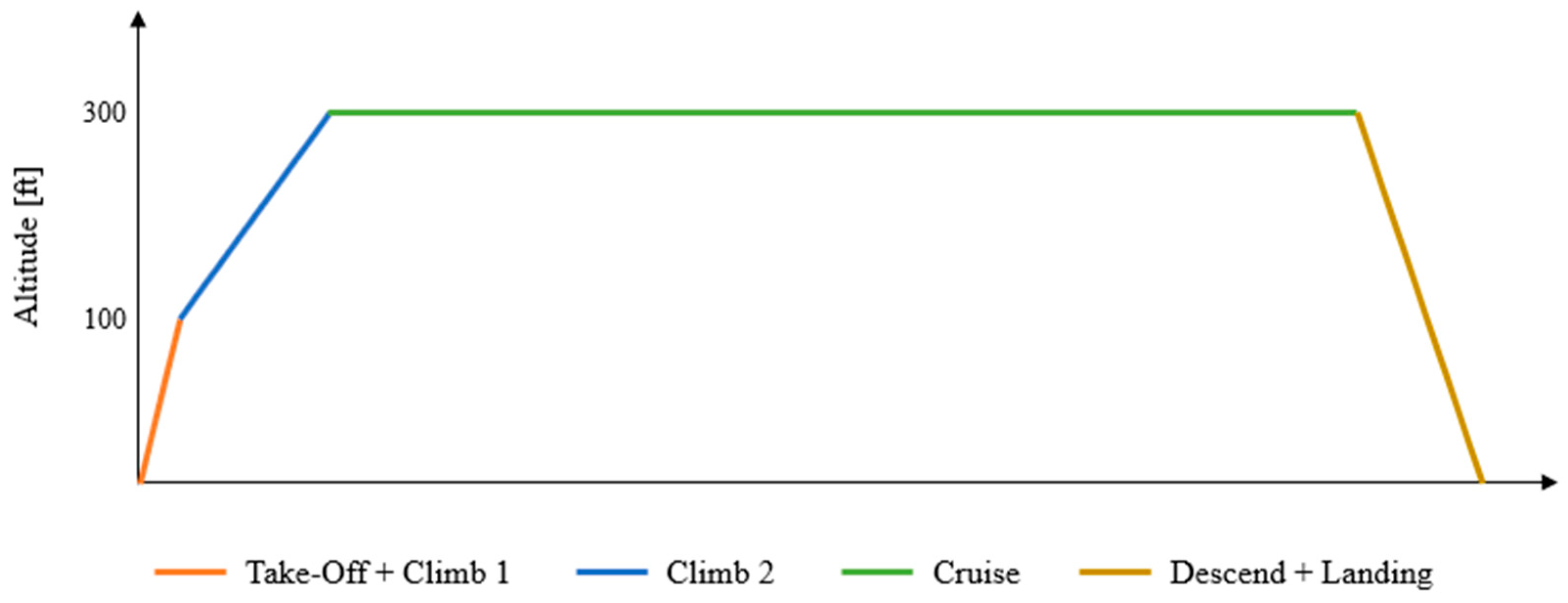
3.2. Mission Profile

As illustrated in Figure 1, the profile of the mission is made up of an initial climb to 100 ft above ground level (AGL) in 30 s. At this altitude, the mission can already be started. The rest of the climb to the cruising altitude of 300 ft AGL is made with a rate of climb (ROC) of 0.5 m/s, and then the cruise is maintained for the rest of the mission for at least 6 h until no energy is available.

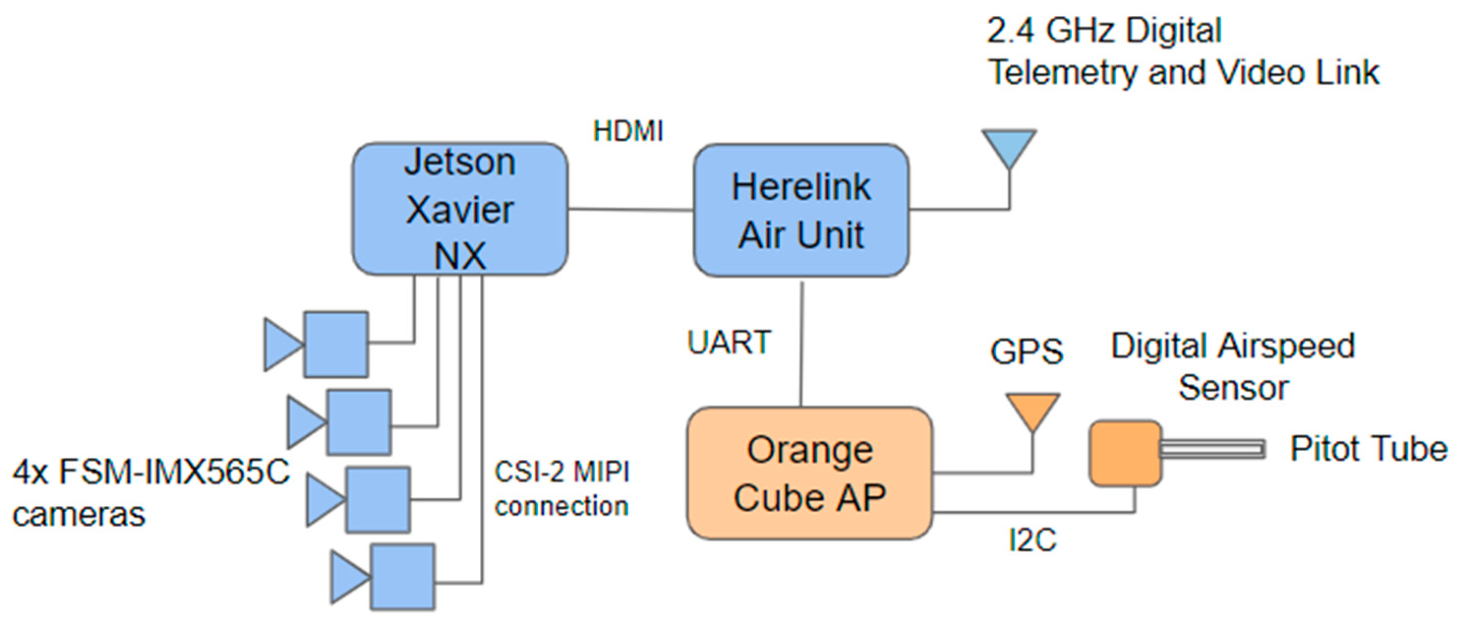
3.3. SPUAV Components

According to what was mentioned before, the third generation of PVCs is best suited for this type of project. However, because these cells are still being tested and are not yet COTS, the market study concluded that the ultra-lightweight eFilm CIGS PVCs from Flisom are the most adequate option for this project. As part of the second generation, its 14% efficiency is not ideal. However, its extraordinary power-to-mass ratio outperforms its direct competitors, including the widely used in the C60 cells UAV industry. In addition, due to its polymeric substrate’s flexibility and its length and width customisations, this PVC is suitable for integration in SPUAVs, allowing the maximisation of solar area depending on the airframe design.
In addition to the PVCs, appropriate avionics and payloads for the designated mission were chosen, and their architecture is displayed in Figure 2. First, we chose four FSM-IMX565C cameras that provide a 360° view with 4K resolution. The Jetson Xavier NX computer and Boson carrier board were elected to process the data gathered by the cameras. The Herelink transmitter and Orange Cube autopilot from CubePilot were selected to transmit images, video, and telemetry to the ground station while ensuring radio control and automatic flight. Finally, the airspeed sensor ASPD-4525 from Matek System was included in the architecture. Overall, the payload weighs approximately 500 g and consumes 45.5 W.

4. Conceptual Design

A design tool has been adapted to estimate the UAV’s flight parameters precisely. This tool is divided into two iterative cycles from which the wing area (S) and MTOM are extracted based on input variables that can be fixed, obtained from market studies of similar UAVs, or optimised (AR and cruise speed).

4.1. Input Variables

First, the aerodynamic data were estimated based on the market study. These include a zero-lift drag coefficient of 0.025, an Oswald factor (e) of 0.85, a maximum lift coefficient o f 1.35, and an initial AR value that will be later optimised of 10.5. Second, we estimated propulsion data based on market studies and previous projects [31,32]. The electronic speed controller (ESC) has a mass of 60 g and an efficiency of 95%, while the propeller weighs 25 g. The engine’s efficiency was conservatively assumed to be 89%, even though 95% efficiency has been achieved before [31,32,33].
Furthermore, a market study on DC brushless motors for 4S batteries, with maximum outputs between 200 and 600 W, led to considering a power-to-mass ratio of 5000 W/kg. A study on propellers with diameters ranging from 13 to 15 inches and several pitches was conducted. Although previous research with similar UAVs has ranged from 11 to 15 inches, a narrower interval was chosen because efficiency decreases with decreasing diameter [32]. Interpolations based on cruise speed, thrust requirements, and propeller performance data from [34] resulted in a mean efficiency of 69% for the cruise and 49% for the climb.
Thirdly, energy data were gathered. The efficiency of PVCs is 14%, and their area-to-mass ratio is 16.67 m2/kg. The mass of the MPPT is 185 g, and its efficiency was considered 95%, slightly lower than the datasheet [35]. Moreover, the mean power-to-mass value of 135 W/kg was estimated based on the LiPo 4S batteries market study, and 75% is the required wing percentage considered for PVC installation.
Additionally, Mermer [36] concluded that a maximum of 91.5% of the wing area is available using the FX-63-137 airfoil due to camber. Nevertheless, a 10% penalty was considered [37]. Then, the mean irradiance level of 524 W/m2 is considered based on the National Solar Radiation Database (NSRDB) from 2017 to 2019. Finally, the model from [22], based on models with high AR, a lack of landing gear, and a low mass-area ratio, was used to obtain the structural mass estimation.

4.2. Inner and Outer Iterative Cycles

Based on the previously calculated variables, we begin the first loop by calculating the thrust and power required for level flight conditions, including the power for payload and avionics, according to [27]. Then, based on the efficiency of the solar system and the average irradiance, the necessary area of PVCs is obtained. Lastly, based on 75% of the wing area needed for PVCs, the inner loop is finished by determining the wing area.
In the second loop, we focus on the climb profile, which is the most demanding phase. The MTOM is calculated by summing the masses of all the components. The mass of the battery is calculated in this cycle based on the amount of energy required. This energy includes both climb phases feeding the avionics and payload and 30 min of extra cruise powering the avionics. The mass of the battery is finally obtained using its energy density and considering a safety factor of 30% to ensure that it does not deplete by the end of the climb.
Considering only the first and most demanding climb, we estimate the engine’s mass using the power-to-mass ratio. Finally, with the calculation of the mass of the PVCs, the outer iterative cycle is completed by determining the MTOM. The mass of the PVCs is achieved by dividing the area retrieved in Section 4.2 by their area-to-mass ratio.

4.3. Conceptual Design Outcome

To optimise the design point of this project, the optimisation variables were applied to the NSGA II algorithm for cruising speeds between 8 and 10 m/s and AR ranging from 8 to 15. The objective functions were to minimise the MTOM and power in the cruise of the UAV, using 50 as population size and 200 generations as input arguments. An optimum solution was obtained for an AR of 11.9 and a cruise speed (UCruise) of 8 m/s. The tendency toward minimum speed is explained to obtain the least amount of power in flight for the same thrust, and the AR is set to the maximum possible without breaking the maximum wingspan constraint. The outcome of the design point has the characteristics presented in Table 2, where b is the wingspan, PCruise is the power for level flight with power to supply the avionics and payload, and UStall is the stall speed.

5. Airframe Design and Energy System

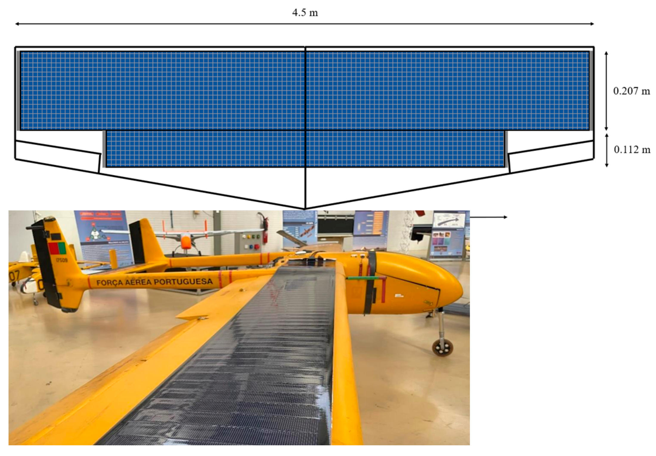
5.1. Airframe Design

Based on the literature review, fixed and flying-wings are the most viable solutions for this project. However, due to the use of twist, swept wings, and larger control surfaces, there are some reservations about the percentage of wing area that can have PVCs installed in the design of the flying-wing. Using CIAFA’s flying-wing expertise, two real models by [37] were used to estimate the percentage of wing area that would be free for PVC installation. Results show that a maximum of 66.5% could accommodate the PVCs in this configuration. Thus, this design will not be considered as 75% or more was needed [36,37].
It is then consensual that the fixed-wing design is the most appropriate. While simultaneously fulfilling the need to install 1.27 m2 of PVCs, an aerodynamically efficient wing is also required. Therefore, we decided to apply taper to the wing. The chosen profile for the study was the FX-63-137, the airfoil with the largest available area studied before. After some calculations, the maximum taper ratio that can be applied is 0.69. As a result, the wing root chord measures 0.45 m and the wing tip chord 0.31 m, allowing the PVCs to be displayed in the wing as shown in Figure 3.

Drag Estimation

In this subsection, XFLR5, a low-fidelity analysis tool for airfoils, wings, and planes, was used to estimate a realistic value of the drag coefficient for the wing of the UAV. First, a 2D analysis of the FX-63-137 airfoil was performed using XFOIL, which outputs drag polars in the final 3D analysis [38]. This program was run with Reynolds numbers ranging from 84,000 to 634,000, Mach 0 values, and angles of attack ranging from −15° to 30°.
Since only the UAV’s wing was investigated in XFLR5, the C D 0 obtained only includes the wing drag. Based on [39] studies, we estimate that the wing has an average contribution of 42.9% to the total drag of the UAV. Thus, a penalty was applied to the new C D 0 , achieving a lower value than the estimate provided to the iterative tool (0.025). For the SPUAV’s cruise speed of 8 m/s, it is roughly 0.0218, meaning that a conservative value was considered in the design tool.

5.2. SPMS

Based on the market consultation and previous discussion, the SPMS of this project is composed of an MPPT, a battery, and a DC-DC converter. First, the MPPT is the GV-10-Li-16.7V from Genasun due to its proven performance in similar projects, as stated in Section 4.1, low weight (185 g) and high efficiency (96–98%). Then, the DC-DC converter turns a maximum voltage input of up to 50 V into 28 V of output to keep the power collected by the PVCs reaching the battery while bridging the excess voltage expected from the PVCs. It is relevant as the PVCs’ open-circuit voltage (VOC) is 48 V, while the maximum voltage input of the MPPT is 34 V.
Lastly, based on the battery mass given by the design tool of 325 g, selected batteries were tested in three conditions. First, the available energy must be at least 43.78 Wh to ensure that a maximum of 70% of its capacity is used. Second, it must be able to discharge at 17.7 A for the climb profile and, lastly, be capable of charging at 10.5 A, which is the current expected in maximum conditions of the MPPT. Thus, the Turnigy Nano-Tech 3000 mAh LiPo battery was chosen for the project.

6. Experiments

The solar cell tests, especially regarding IV curves, involve a detailed procedure to assess the performance and efficiency of the solar cell. The process begins with preparation, ensuring the solar cell is clean and set up in a controlled environment. Equipment setup follows, with the solar cell connected to a source meter or IV tester, and often, a solar simulator is used to mimic natural sunlight.
To establish performance metrics, the testing starts with baseline measurements under no-load and open-circuit conditions. The crux of the test is the IV curve tracing. Here, the voltage applied to the solar cell varies, and the current at each step is measured to plot the IV curve. This curve is vital for analysing performance, highlighting key points such as short-circuit current, open-circuit voltage, maximum power point, fill factor, and efficiency.
After plotting the IV curve, data analysis calculates the solar cell’s efficiency, a crucial performance parameter. The tests are often repeated under varying environmental conditions, such as different temperatures and light intensities, to gauge the solar cell’s behaviour in different scenarios.
Finally, the results are compared with standard values or those of other solar cells to benchmark performance. This comparison helps determine the solar cells’ quality and viability. The tests are repeated to ensure data consistency and reliability, comprehensively evaluating the solar cell’s performance under simulated conditions and offering valuable insights into its operational capabilities and efficiency.

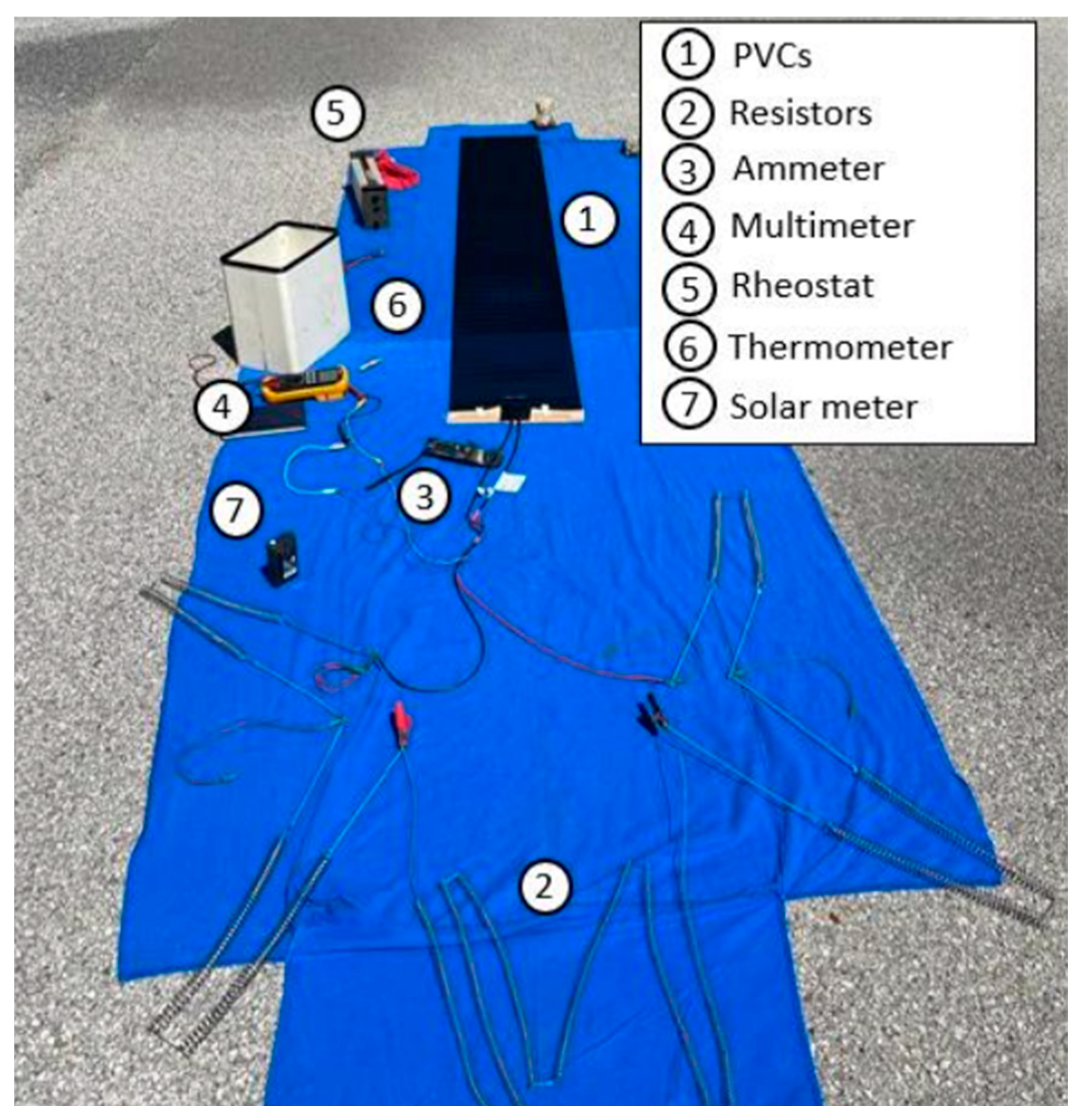
6.1. Experimental Constraints

In contrast to what was proposed in the previous sections, it was necessary to conduct these experiments with different equipment due to this project’s limited timeline and budget. The PVCs and battery were chosen keeping the basic characteristics, namely CIGS technology and LiPo 4S, but disregarding the weight variable because only ground tests will be performed.
The tests will be conducted using a solar system comprised of a PVC CIGS panel of 125 W with a power-to-mass ratio of 54 W/kg, a 5000 mAh 4S LiPo battery, the previously selected MPPT, an 11 × 6 propeller with the AT2820 KV1050 motor, and an ESC from T-Motor.

6.2. Battery Discharge

This experiment aims to study the battery’s behaviour and stability during a full discharge in the most demanding phase of the flight. Thus, the test consists of keeping the engine power at 262 W while being fed by the battery. As voltage drops, throttle adjustments are required, increasing current to maintain the power output. The battery discharged in 14 min 40 s, achieving a maximum temperature of 34.3 °C. Through a theoretical calculation and considering a 30% safety factor, the ideal 3000 mAh battery would discharge in 8 min and 45 s.

6.3. Battery Charge with MPPT

The second experiment was planned to test MPPT electrical parameters and efficiency. This is carried out by connecting the MPPT to the battery with roughly 12 V while receiving 170 W with 34 V from a DC power source. These parameters are limit conditions for the MPPT. The battery charged in 21 min 30 s until 16.63 V, with an initial peak of nearly 11 A, which may be caused by the battery’s depth of discharge (DOD). A nominal current of 9 to 10 A was then recorded. Nevertheless, the MPPT’s current output did not vary with the battery’s state of charge (SOC).
The maximum temperature of the battery was 21.5 °C, and the MPPT reached 42 °C, which is still well below the maximum studied by Genasun of 85 °C. Considering the maximum input power of the MPPT, the average experimental efficiency is 92.4%, which was slightly lower than expected.

6.4. Flight Profile with DC Power Source

This test pretends to perform three flight profiles, simulating the entire energy system but replacing the PVCs with a DC power source. Each test was performed with different weather conditions simulated by the source’s power input, according to the NSRDB.
The first test was conducted with the mean irradiance of August, with the highest irradiance levels. The goal is to study the system’s behaviour, that is, the compatibility between equipment and temperature stability, as this is the first time the battery is charging and discharging simultaneously. A good performance was evidenced during the 6 h test, with the battery voltage not dropping below 16.3 V. Battery and MPPT temperature peaks were 18 °C and 37.3 °C, respectively.
The second test was performed with the average of the worst month in terms of irradiance, December. In these conditions, the system will receive less power than used in the design tool, meaning that the SPUAV will not complete a 6 h flight. The battery discharges continuously, but the discharge rate decreases over time due to the irradiance increments. The trial lasted 1 h 5 min, and the estimated flight time with the ideal battery is 35 min. The battery temperature peak was 22.6 °C, and the MPPT did not reach 20 °C.
The last test was carried out with the period average included in NSRDB. Initially, the battery discharges due to the low irradiance until 15.54 V, where an SPMS efficiency of 89% was recorded. Later, with the increase in irradiance, the battery charges until 16.55 V before discharging again at the end of the test. The endurance was 7 h 34 min, and adapting this result to the 3000 mAh battery yields an endurance of 7 h 5 min. In this case, the battery temperature reaches its maximum at the end of the test at roughly 23 °C, and the MPPT is very stable, between 32 and 35.1 °C.

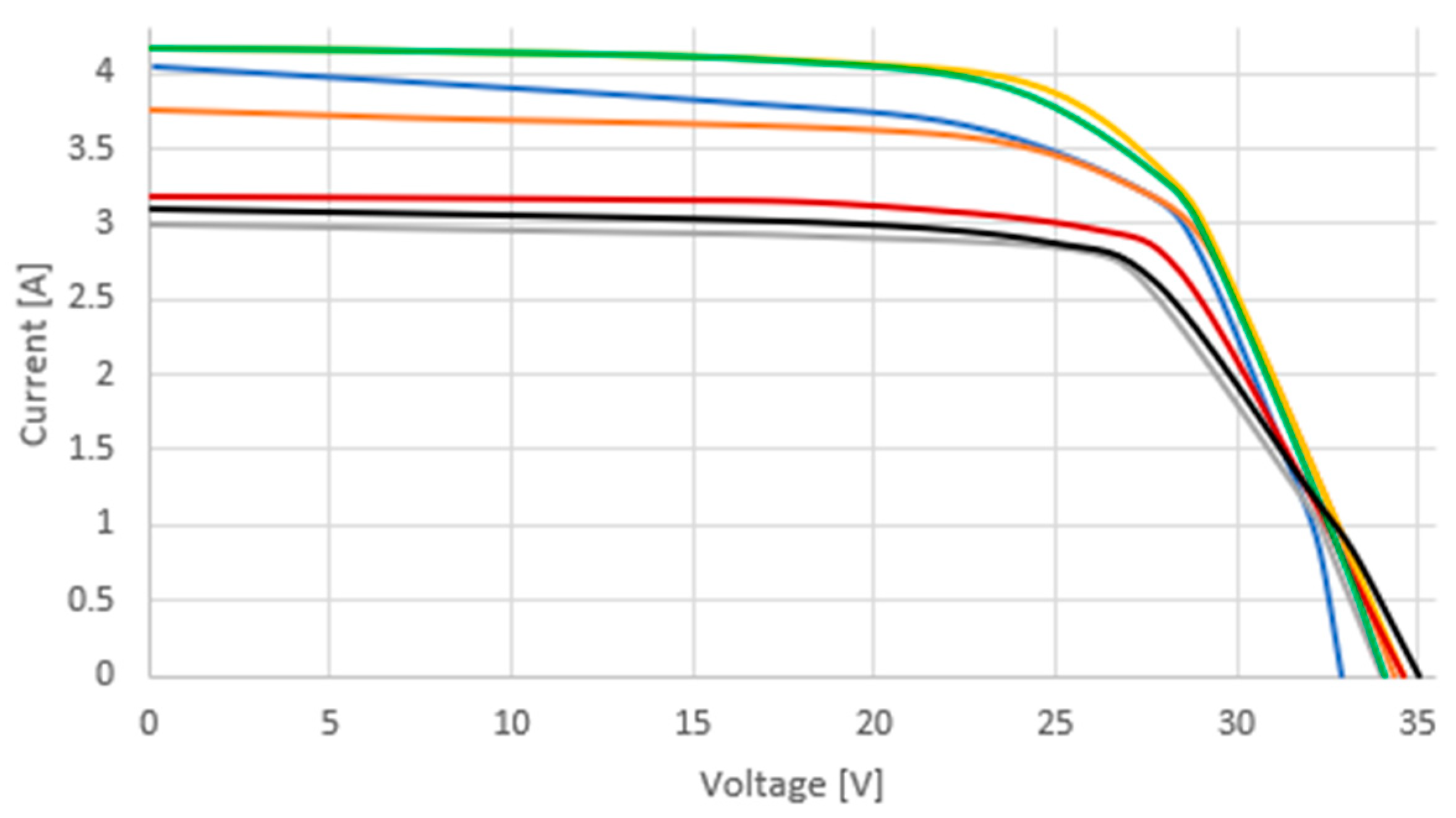
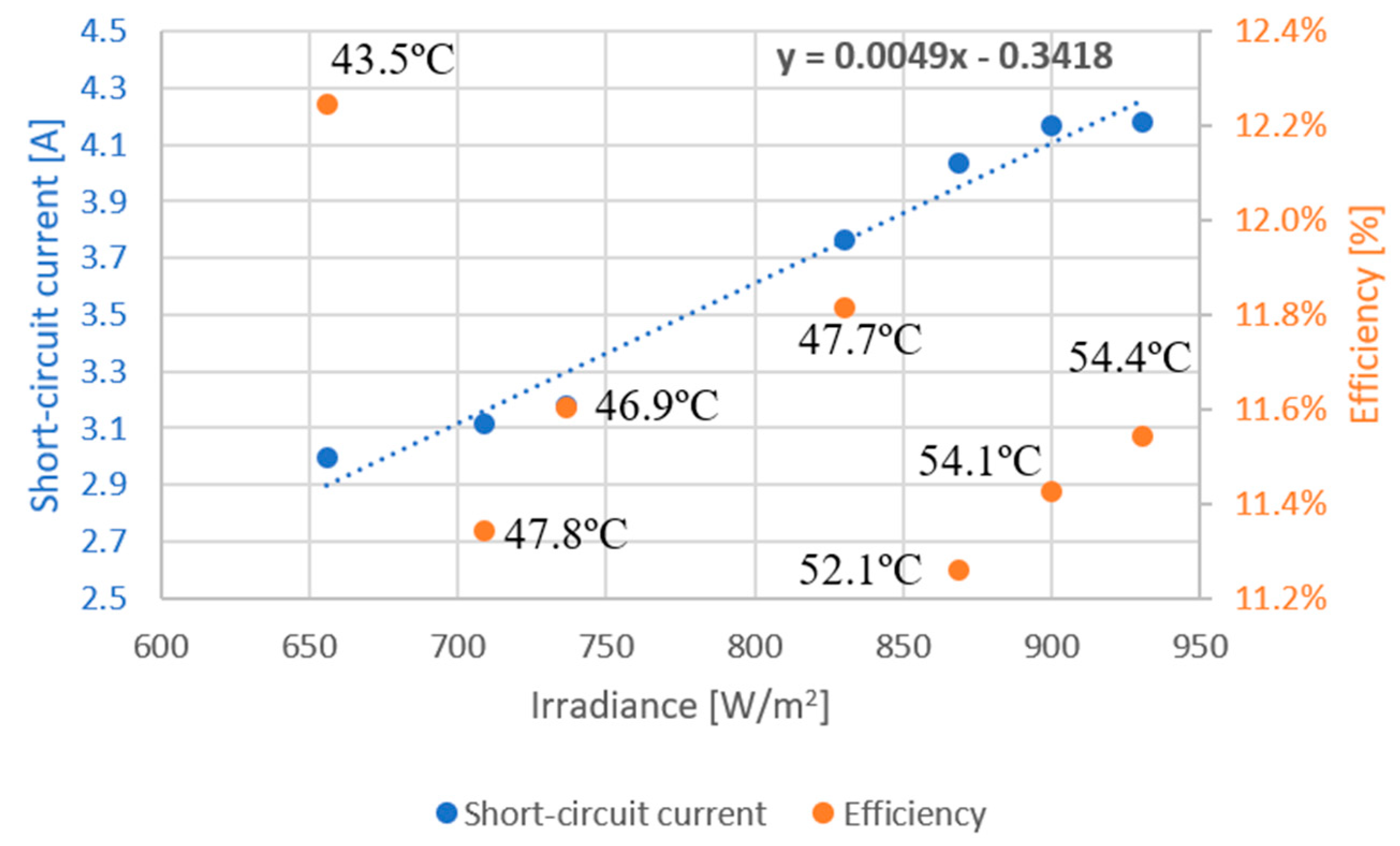
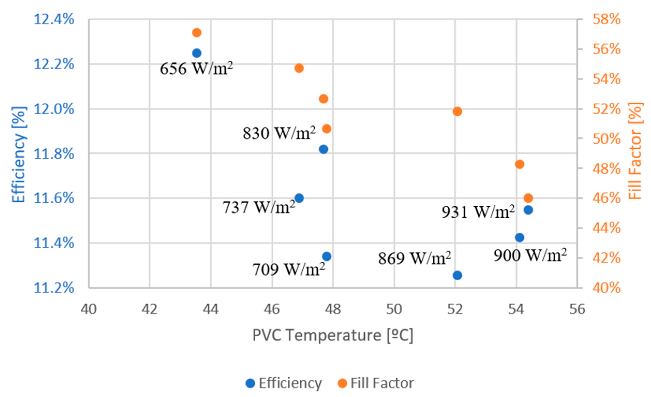
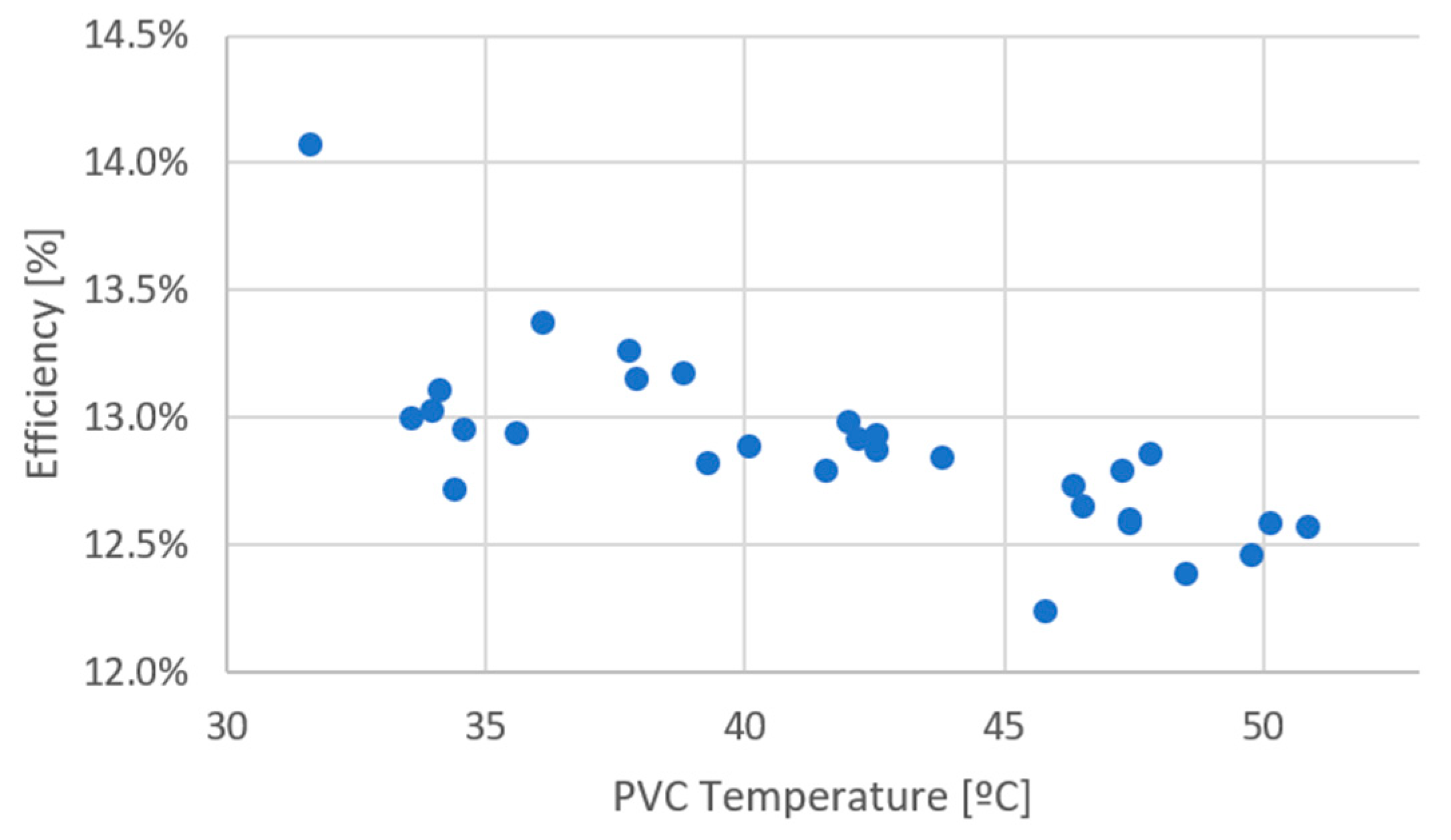
6.5. PVCs Electrical Characteristics

The purpose of this subsection is to characterise the behaviour of the PVCs before their installation in the solar system. Several tests were conducted on different days with PVCs connected to various resistances in two ranges, one from 0 to 12 Ω and the other from 25 to 45 Ω, as presented in Figure 4, recording IV curves. There are several electrical models for this matter, but the 1M5P model was chosen as it is the most commonly used [40].
A computational tool was created to solve nonlinear equations using iterative methods, namely, PVC current concerning its output voltage as defined by [41]. This retrieved the five parameters from the 1M5P model. The n, the diode non-ideality factor, varied from 10.85 to 48.68; the IL, the photogenerated current, was between 3.02 and 4.27; the series resistance was between 0.72 and 2.18; the shunt resistance was from 57.44 to 383.24; and the I0, the reverse diode current, was nearly null in all the trials, removing the diode’s exponential effect [42,43]. As a result, the extracted curves are straight lines with a negative slope, and the experimental VOC’s current is far from zero. The results highlight one of the major drawbacks of using this model, as pointed out by [42], that the five parameters are obtained from a small number of points.
Alternatively, [42] proposes a novel d1MxP model to solve this accuracy problem by studying the cell’s performance between adjacent points. The foundation of this model is the discretisation of the diode’s electrical operation through the decomposition of the diode into several branches in parallel. Each branch comprises an adjustable ideal diode, a resistance, and an ideal and independent voltage source. In contrast to the 1M5P model, the seven curves were successfully generated and are shown in Figure 5. A certain point is considered an outlier if the current increases with voltage and if the next slope’s module is not greater than the previous. Between two to four points per curve were considered model outliers.
Furthermore, to estimate the cell’s perfection, the fill factor (FF) for all the trials is calculated based on [43,44], achieving an average value for the PVC module of 51.6%, which means that the curve is approximately half of the perfect rectangle formed by the VOC, short-circuit current (ISC), and a perfect maximum power point (MPP). Additionally, efficiency is a very commonly used parameter to compare different types of cells. An efficiency between 11.3% and 12.3% was evidenced in the different trials.
According to [22], I S C increases linearly with the irradiance increasing. The increase in PVC temperature, known to cause PVC degradation, results in a significant decrease in V O C and a slight reduction in I S C , efficiency and fill factor. The experimental validation in Figure 6 showed that, in general, the irradiance effect was noticeable according to the literature. In addition, the PVC temperature at each efficiency point is represented.
However, the PVC temperature effect in V O C does not tend to vary with temperature, whereas I S C varies in the opposite direction, increasing with temperature. Figure 7 depicts efficiency and fill factor decline with temperature increments, as expected. The unexpected results in temperature correlation can be explained by the short temperature range recorded during the tests and because irradiance and temperature varied as the tests were not conducted in a controlled environment [45]. Irradiance is also represented for each efficiency point.

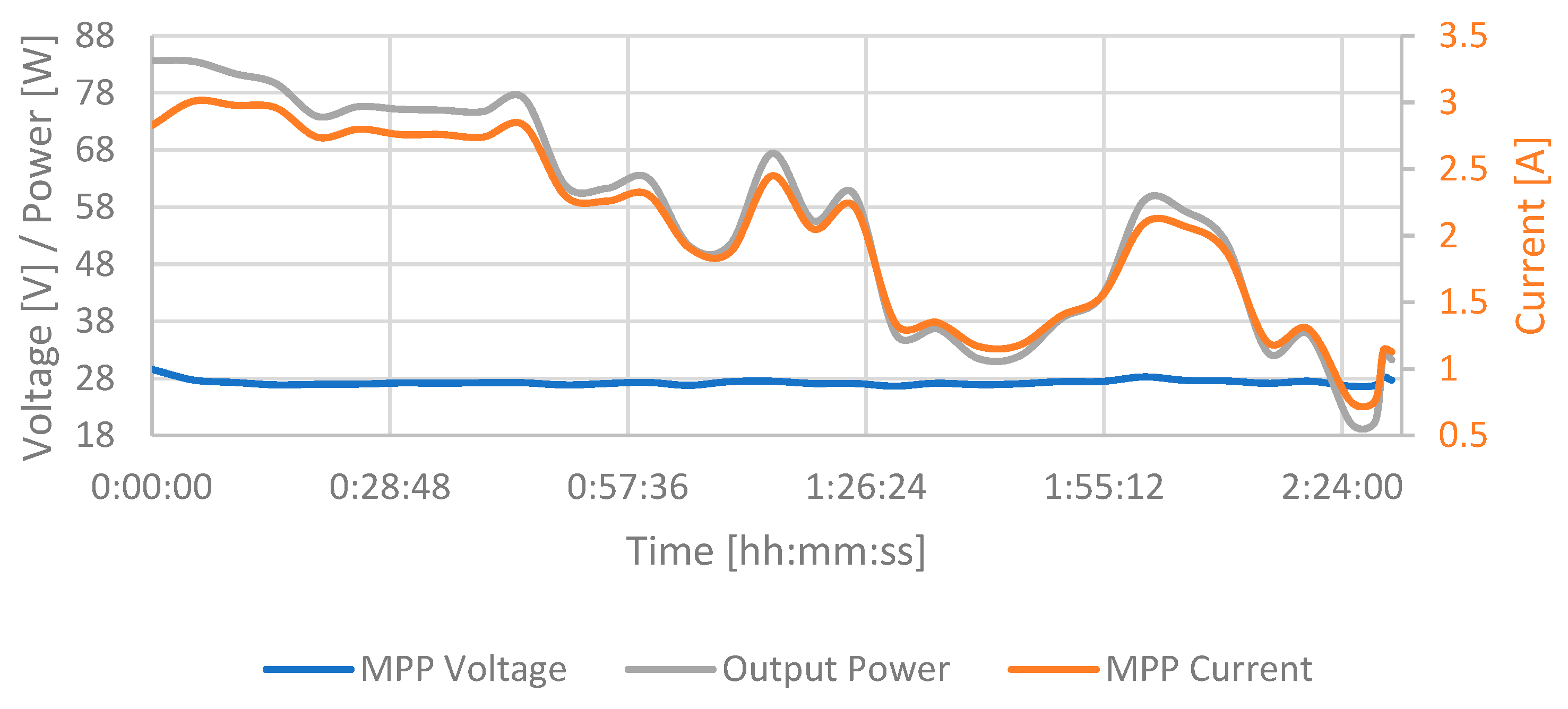
6.6. Flight Profile with PVCs

Finally, the full solar system was tested to calculate the efficiency of the PVC while integrated into the system and to estimate the SPUAV’s endurance. The test was conducted in April during a slightly cloudy afternoon with temperatures ranging from 26 to 23 °C. First, during one hour in the cruise phase with an average irradiance of 955 W/m2, the SPMS efficiency recorded was more than 96%. It is a significant increase from PVCs, which had an efficiency of 9.9%.
Afterwards, at the end of the afternoon, 2 h and 30 min of testing were completed following the start of the battery discharge. This means an estimated SPUAV endurance of 7 h 49 min, with irradiance ranging from 750 to 160 W/m2. The battery, PVCs, and MPPT reached maximum temperatures of 37.1, 50.9, and 41.6 °C, respectively. PVC voltage has only minor oscillations, indicating that the power output variation due to irradiance is managed by lowering the module’s current, as visible in Figure 8. Moreover, as irradiance increases, the battery’s discharging curve slows down, except when the battery has already reached a high DOD.
Lastly, the average efficiency of the PVCs is 12.9%, which is significantly higher than in the first test of this subsection, ranging between 11.3 and 14.1%. The inversely proportional relationship between efficiency and temperature was confirmed in this case, with a wider range of temperatures as appropriate, as shown in Figure 9.

7. Conclusions

This work aims to present a solution for using solar energy for UAV operation that reduces the environmental impact of this type of aviation and overcomes its endurance limitations. This goal was accomplished by using a method that progressed from conceptual study to experimental proof of the SPMS and PVCs, allowing the presentation of a UAV design that can now be built and tested.
In the initial phase, the state-of-the-art review enabled the study and evaluation of PVC technology and battery types based on their advantages and disadvantages. Afterwards, during the conceptual design of the SPUAV, CIGS cells with a power-to-mass ratio of more than 2000 W/kg and the avionics and payload were selected. Subsequently, based on aerodynamic, propulsion, energy, and weight variables, a design point of a UAV with a wing area of 1.70 m2, of which 1.27 m2 are for PVCs, 4.5 m of wingspan, an aspect ratio of 11.9, a weight of 4.33 kg, and a cruising speed of 8 m/s was achieved using a computational tool.
Due to procurement constraints, experimental validations were performed with a 125 W CIGS panel, a 5000 mAh LiPo battery, an 11 × 6 propeller, and the AT2820 KV1050 motor from T-Motor. Testing revealed that charging the battery via the MPPT is completed in 21 min and 30 s with an efficiency of 92.4%. Further testing concluded that with the solar system connected to a DC power source instead of the PVCs, the SPUAV would fly for 35 min in the worst-case scenario. On an average day of the year, with the average irradiance, the estimated in-flight endurance is 7 h 5 min.
Afterwards, the PVCs were electrically characterised using the d1MxP model proposed in [41], revealing a mean fill factor and efficiency of 51.6% and 11.6%, respectively. Furthermore, the study demonstrated that an increase in irradiance causes an increase in ISC and a decrease in panel efficiency, while increasing the temperature of PVCs triggers a decrease in efficiency and fill factor. Lastly, with the complete solar system, SPMS efficiency improved to roughly 96%. The panel demonstrated an efficiency of 9.9% when the battery was fully charged and ranged between 11.3 and 14.1% when the battery was charging. The estimated endurance on the day of the test was 7 h 49 min.
To summarise, this work provided CIAFA with knowledge in a previously unstudied area, with major contributions including developing a computational tool for designing SPUAVs and a methodology for ground testing an energy and propulsion system to be used onboard these airframes.

Author Contributions

Conceptualization: J.P.S.S., G.C., V.C., J.P.N.T. and R.A.M.L.; methodology: J.P.S.S., G.C., V.C., J.P.N.T. and R.A.M.L.; investigation: J.P.S.S., G.C., V.C., J.P.N.T. and R.A.M.L.; writing—original draft: J.P.S.S.; writing—review and editing: G.C., V.C., J.P.N.T. and R.A.M.L.; All authors have read and agreed to the published version of the manuscript.

Funding

This work was partly supported by FCT/MCTES through national funds and partly by cofounded EU funds under Project UIDB/50008/2020. FCT also supported this work under the UI/BD/151091/2021 research grant.

Data Availability Statement

Data is available on request.

Conflicts of Interest

The authors declare no conflict of interests.

References

  1. Dui, H.; Zhang, C.; Bai, G.; Chen, L. Mission reliability modeling of UAV swarm and its structure optimization based on importance measure. Reliab. Eng. Syst. Saf. 2021, 215, 107879. [Google Scholar] [CrossRef]
  2. Thirugnanasambandam, M.; Iniyan, S.; Goic, R. A review of solar thermal technologies. Renew. Sustain. Energy Rev. 2010, 14, 312–322. [Google Scholar] [CrossRef]
  3. Boucher, R.J. History of solar flight. In Proceedings of the Em AIAA/SAE/ASEE 20th Joint Propulsion Conference, Cincinnati, OH, USA, 11–13 June 1984. [Google Scholar] [CrossRef]
  4. Shiau, J.K.; Ma, D.M.; Yang, P.Y.; Wang, G.F.; Gong, J.H. Design of a solar power management system for an experimental UAV. IEEE Trans. Aerosp. Electron. Syst. 2009, 45, 1350. [Google Scholar] [CrossRef]
  5. de Carvalho Bertoli, G.; Pacheco, G.M.; Adabo, G.J. Extending flight endurance of electric unmanned aerial vehicles through photovoltaic system integration. In Proceedings of the Em 2015 International Conference on Renewable Energy Research and Applications (ICRERA), Palermo, Italy, 22–25 November 2015; pp. 143–147. [Google Scholar]
  6. Chawla, R.; Singhal, P.; Garg, A.K. Photovoltaic review of all generations: Environmental impact and its market potential. Trans. Electr. Electron. Mater. 2020, 21, 456–476. [Google Scholar] [CrossRef]
  7. Ya’u Muhammad, J.; Bello Waziri, A.; Muhammad Shitu, A.; Muhammad Ahmad, U.; Hassan Muhammad, M.; Alhaji, Y.; Taofeek Olaniyi, A.; Abdulkadir Bala, A. Recent progressive status of materials for solar photovoltaic cell: A comprehensive review. Sci. J. Energy Eng. 2019, 7, 77. [Google Scholar] [CrossRef]
  8. NREL Best Research-Cell Efficiency Chart. Photovoltaic Research. 2022. Available online: https://www.nrel.gov/pv/cell-efficiency.html (accessed on 1 June 2023).
  9. Mitzi, D.B.; Yuan, M.; Liu, W.; Kellock, A.J.; Chey, S.J.; Gignac, L.; Schrott, A.G. Hydrazine-based deposition route for device-quality CIGS films. Thin Solid Film. 2009, 517, 2158–2162. [Google Scholar] [CrossRef]
  10. Green, M.A. Third generation photovoltaics: Ultra-high conversion efficiency at low cost. Prog. Photovolt. Res. Appl. 2001, 9, 123–135. [Google Scholar] [CrossRef]
  11. Teixeira, C.O.; Andrade, L.; Mendes, A. Easy processing carbon paper electrode for highly efficient perovskite solar cells. J. Power Sources 2020, 479, 229071. [Google Scholar] [CrossRef]
  12. Smith, A.B.; Jones, C.D. Modern Photovoltaics: Principles and Applications. Energy Sci. J. 2024, 30, 123–134. [Google Scholar]
  13. Lee, H.Y. Multi-Junction Solar Cells: The Future of Solar Energy. Renew. Energy Rev. 2023, 17, 45–60. [Google Scholar]
  14. Green, M.; Brown, S. Thin-Film Solar Cells: Materials and Technologies. Sol. Energy Mater. 2024, 29, 321–333. [Google Scholar]
  15. Patel, R.; Kumar, S. Organic Photovoltaics and Dye-Sensitized Solar Cells. J. Sol. Energy Eng. 2023, 31, 210–225. [Google Scholar]
  16. Saha, B.; Koshimoto, E.; Quach, C.C.; Hogge, E.F.; Strom, T.H.; Hill, B.L.; Vazquez, S.L.; Goebel, K. Battery health management system for electric UAVs. In Proceedings of the IEEE Aerospace Conference Proceedings, Big Sky, MT, USA, 5–12 May 2011. [Google Scholar] [CrossRef]
  17. Hohm, D.P.; Ropp, M.E. Comparative study of maximum power point tracking algorithms. Prog. Photovolt. Res. Appl. 2003, 11, 47–62. [Google Scholar] [CrossRef]
  18. Zhang, X.; Li, M. Beyond Lithium-Ion: Emerging Battery Technologies for Solar Applications. Battery Sci. 2024, 12, 134–145. [Google Scholar]
  19. Kim, D.E.; Park, S.H. Advances in Battery Management Systems for Renewable Energy. Energy Storage 2023, 8, 50–65. [Google Scholar]
  20. Morton, S.; D’Sa, R.; Papanikolopoulos, N. Solar powered UAV: Design and experiments. In Proceedings of the Em IEEE International Conference on Intelligent Robots and Systems, Hamburg, Germany, 28 Septemeber–2 October 2015; pp. 2460–2466. [Google Scholar] [CrossRef]
  21. Butler, C.; Costello, M. Vehicle design in aerial robotics. Curr. Robot. Rep. 2021, 2, 415–426. [Google Scholar] [CrossRef]
  22. Floreano, D.; Wood, R.J. Science, technology and the future of small autonomous drones. Nature 2015, 521, 460–466. [Google Scholar] [CrossRef]
  23. D’Sa, R.; Henderson, T.; Jenson, D.; Calvert, M.; Heller, T.; Schulz, B.; Kilian, J.; Papanikolopoulos, N. Design and experiments for a transformable solar-UAV. In Proceedings of the Em Proceedings—IEEE International Conference on Robotics and Automation, Singapore, 29 May–3 June 2017; pp. 3917–3923. [Google Scholar] [CrossRef]
  24. Chen, W.; Liu, F. Carbon Fiber Composites in UAV Design. Aerosp. Mater. Handb. 2023, 22, 78–89. [Google Scholar]
  25. Murphy, K. Bio-Inspired UAV Design: Lessons from Nature. J. Aeronaut. 2024, 15, 150–162. [Google Scholar]
  26. Anderson, J.D. Aircraft Performance and Design. Thomas Casson. 1999. Available online: https://www.academia.edu/8768700/Anderson_aircraft_performance_and_design (accessed on 1 June 2023).
  27. Raymer, D. Aircraft Design: A Conceptual Approach, 6th ed.; American Institute of Aeronautics and Astronautics: Reston, VA, USA, 2018. [Google Scholar] [CrossRef]
  28. Sadraey, M.H. Aircraft Design: A Systems Engineering Approach; Jones, R., Smith, L., Eds.; John Wiley & Sons: Hoboken, NJ, USA, 2012. [Google Scholar]
  29. Gupta, A.; Kumar, N. Solar Integration in Aircraft Wings: Challenges and Prospects. Sol. Energy Eng. 2023, 25. [Google Scholar] [CrossRef]
  30. Parada LM, A.; Marta, A.C. Conceptual and Preliminary Design of a Long Endurance Electric UAV; Instituto Superior Técnico: Lisbon, Portugal, 2016; Available online: https://fenix.tecnico.ulisboa.pt/downloadFile/1970943312279037/LuisParada_ExtendedAbstract.pdf (accessed on 1 June 2023).
  31. Vidales, H.M.G.; Marta, A.C. Design, Construction and Test of the Propulsion System of a Solar UAV; Instituto Superior Técnico: Lisbon, Portugal, 2013; Available online: https://www.semanticscholar.org/paper/Design%2C-Construction-and-Test-of-the-Propulsion-of-Vidales/ebb26cb110ae0b1af30b5ab8f307d17d501f5c7f (accessed on 1 June 2023).
  32. Gieras, J.F. Design of permanent magnet brushless motors for high speed applications. In Proceedings of the 17th International Conference on Electrical Machines and Systems, ICEMS, Hangzhou, China, 22–25 October 2014. [Google Scholar] [CrossRef]
  33. Propeller Performance Data. APC Propellers. 2014. Available online: https://www.apcprop.com/technical-information/performance-data/ (accessed on 1 June 2023).
  34. Ferreira, T.; Marta, A.C.; Infante, V.I.M.N. Hybrid Propulsion System of a Long Endurance Electric UAV; Instituto Superior Técnico: Lisbon, Portugal, 2014. [Google Scholar]
  35. Mermer, E.; Koker, A.; Kurtulus, D.F.; Yilmaz, E.; Uzay, T. Design and performance of wing configurations for high altitude solar powered unmanned system. In Proceedings of the Ankara International Aerospace Conference, Ankara, Turkey, 11–13 September 2013; Available online: https://www.researchgate.net/publication/281461742 (accessed on 1 June 2023).
  36. Noth, A.; Siegwart, R.; Engel, W. Design of Solar Powered Airplanes for Continuous Flight. Ecole Polytechnique Fédéral de Lausanne. 2008. Available online: https://ethz.ch/content/dam/ethz/special-interest/mavt/robotics-n-intelligent-systems/asl-dam/documents/phd_thesis/Andre_Noth_Design_of_Solar_Powered_Airplanes_for_Continuous_Flight.pdf (accessed on 1 June 2023).
  37. Silva, R.; Félix, L.; Oliveira, T. Projeto Conceptual de Uma Aeronave Pequena de Baixo Custo para Aplicações em Controlo Cooperativo. Academia da Força Aérea. 2020. Available online: https://comum.rcaap.pt/bitstream/10400.26/39752/1/DissertacaoMestrado_ASPAL_PILAV_139418-F_Silva.pdf (accessed on 1 June 2023).
  38. Drela, M.; Youngren, H. XFOIL 6.94 User Guide (p. 33). 2001. Available online: http://clubmodelisme.free.fr/liens/files/xfoil/xfoil_doc.pdf (accessed on 1 June 2023).
  39. Götten, F.; Havermann, M.; Braun, C.; Gómez, F.; Bil, C. On the applicability of empirical drag estimation methods for unmanned air vehicle design. In Proceedings of the Aviation Technology, Integration, and Operations Conference, Atlanta, GA, USA, 25–29 June 2018. [Google Scholar] [CrossRef]
  40. Castro, R.; Silva, M. Experimental and theoretical validation of one diode and three parameters-based pv models. Energies 2021, 14, 2140. [Google Scholar] [CrossRef]
  41. Song, Z.; Fang, K.; Sun, X.; Liang, Y.; Lin, W.; Xu, C.; Huang, G.; Yu, F. An effective method to accurately extract the parameters of single diode model of solar cells. Nanomaterials 2021, 11, 2615. [Google Scholar] [CrossRef] [PubMed]
  42. Torres, J.P.N.; Marques Lameirinhas, R.A.; Bernardo, C.V.; Catarina, P.; Veiga, H.I.; dos Santos, P.M. A discrete electrical model for photovoltaic solar cells—d1MxP. Energies 2023, 16, 2018. [Google Scholar] [CrossRef]
  43. Bernardes, S.; Lameirinhas, R.A.M.; Torres, J.P.N.; Fernandes, C.A. Characterization and design of photovoltaic solar cells that absorb ultraviolet, visible and infrared light. Nanomaterials 2021, 11, 78. [Google Scholar] [CrossRef]
  44. Pastuszak, J.; Węgierek, P. Photovoltaic cell generations and current research directions for their development. Materials 2022, 15, 5542. [Google Scholar] [CrossRef]
  45. Marques Lameirinhas, R.A.; Torres, J.P.N.; de Melo Cunha, J.P. A photovoltaic technology review: History, fundamentals and applications. Energies 2022, 15, 1823. [Google Scholar] [CrossRef]
Figure 1. Non-scaled mission profile (figure not to scale).
Vehicles 05 00100 g001
Figure 2. Avionics and payload architecture.
Vehicles 05 00100 g002
Figure 3. Non-scaled SPUAV wing design with PVCs installed (figure not to scale).
Vehicles 05 00100 g003
Figure 4. Experimental set-up.
Vehicles 05 00100 g004
Figure 5. d1MxP IV curves from the seven experiments.
Vehicles 05 00100 g005
Figure 6. Irradiance effect on short-circuit current and PVC efficiency.
Vehicles 05 00100 g006
Figure 7. Temperature effect on PVC efficiency and fill factor.
Vehicles 05 00100 g007
Figure 8. PVC behaviour during battery discharge with the full solar system.
Vehicles 05 00100 g008
Figure 9. PVC’s efficiency correlates with their temperature during the test with the full solar system.
Vehicles 05 00100 g009
Table 1. Project requirements by CIAFA.
RequirementValueDescription
MTOM<25 kgPreferable <10 kg
Wingspan≤4.5 m-
Endurance6 h -
Power-Battery, solar cells
Payload-Include 360° surveillance cameras.
Cruising speed≥8 m/s-
Stall speed-80% of cruising speed
Altitude300 ftAbove ground level
Table 2. SPUAV design point characteristics.
S A P V C bARMTOM P C r u i s e P C l i m b _ 1 U S t a l l U C r u i s e
1.70 m21.27 m24.5 m11.94.33 kg80 W262 W5.7 m/s8 m/s
Disclaimer/Publisher’s Note: The statements, opinions and data contained in all publications are solely those of the individual author(s) and contributor(s) and not of MDPI and/or the editor(s). MDPI and/or the editor(s) disclaim responsibility for any injury to people or property resulting from any ideas, methods, instructions or products referred to in the content.

