Article

Electric Motor and Transmission Integration for Light-Duty Electric Vehicles: A 2023 Benchmarking Perspective and Component Sizing for a Fleet Approach

by
Darrell Robinette
Mechanical Engineering-Engineering Mechanics, Michigan Technological University, Houghton, MI 49931, USA
Vehicles 2023, 5(3), 1167-1195; https://doi.org/10.3390/vehicles5030065
Submission received: 21 July 2023 / Revised: 20 August 2023 / Accepted: 26 August 2023 / Published: 14 September 2023

Abstract

:
A review of past, current, and emerging electric vehicle (EV) propulsion system technologies and their integration is the focus of this paper, namely, the matching of electric motor (EM) and transmission (TRM) to meet basic requirements and performance targets. The fundaments of EM and TRM matching from a tractive effort and a vehicle dynamics perspective are provided as an introductory context to available or near-production propulsion system products available from OEM and Tier 1 suppliers. Engineering data and details regarding EM and TRM combinations are detailed with a specific focus on volumetric and mass density. Evolutionary trends in EM and TRM technologies have been highlighted and summarized through current and emerging products. The paper includes an overview of the initial EV propulsion system’s sizing and selection for a set of simple requirements that are provided through an examination of three light-duty EV applications. An enterprise approach to developing electrified propulsion modules with suitable applicability to a range of light-duty EVs from compact cars to full-size trucks concludes the paper.

1. Introduction

The rapid growth of light-duty EV mobility products from the mid-2010s to the present, as noted in [1,2,3,4,5,6], has necessarily required a shift in the propulsion system engineering and research and development communities. Engineering development has gradually shifted from conventional to hybrid, then to plug-in hybrid, and now to fully electric technologies that optimally blend performance, efficiency, durability, reliability, and cost (see [5] for an exemplary description of this). State-of-the-art light-duty EV propulsion technology can be found abundantly in the literature, see [5,6,7,8] for example. EM topology investigations that explore tradeoffs in the balance of the performance of permanent magnet synchronous machines (PMSMs), induction machines (IMs), switched reluctance machines (SRMs), permanent magnet brushless direct current (PMBLDC), and wound rotor synchronous machines (WRSMs) overshadow the literary landscape (see [5,6,7,8,9,10]), especially as the industry is motivated to reduce its reliance on rare earth materials. These articles also provide a means to extract trends in EM technology that migrate to the production of EVs. Research studies by [11,12,13,14,15,16,17,18,19] have focused on advanced new EM design, construction, and control strategies, enabling higher torque density, minimal to zero use of rare earth materials, and reduced torque ripple and/or improved torque delivery for drivability, respectively. The direction of magnetic flux, which is traditionally radial in PMSMs, has been shown analytically [18,20,21], experimentally [7], and in the production of EMs [22,23] to provide benefits in torque and packaging. Similar to studies by [5,6,7,8], a historical perspective, from the early 2000s to the present (2023), on EMs is provided in terms of performance and packaging [9,11,17,18,20,24,25], showing PMSMs to comprise a majority of the topology and yield the highest performance and smallest packaging, which are achieved through a highly proprietary and innovative systems-level-integrated design approach [26,27,28,29,30].
Downstream of the EM, the EV transmission (TRM) has also been the subject of much research, with the authors of [4,31,32] providing excellent summaries of TRM designs specific to EV propulsion systems from the early 2000s to the present. Single-speed TRMs are nearly the singular choice for EVs with, at most, two-production, two-speed designs [4,31,32,33,34,35,36], with a sizeable amount of proposed two-speed or more designs in the literature [37,38,39,40,41,42,43,44,45,46,47,48,49,50,51] that utilize parallel axes and planetary, belt, or transfer chain torque transfer mechanisms. Many studies have shown the matching process of the EM and TRM as a system, whether as a simplified graphical approach [52], a high-fidelity digital twin capable of initial matching to fault detection or predictive maintenance [53], or as detailed electrical-mechanical models that are paired with AI to optimize energy consumption and drivability [54]. Single- and multi-speed EV TRM topologies that contain one or two EMs are found in [4,31,32,42] and are emphasized again later in the paper. Novel electric traction drive units that contain two EMs and gearing that can split power between EMs, such as [55], are not discussed.
This paper is a combination of the reviewed literature and original research with three main objectives: (1) to offer a high-level summary of the current state of production or near-production EMs in terms of performance and packaging; (2) to present a power flow summary of single- and multi-speed EV TRMs that are in mainstream production or are contained in the literature and that represent production-worthy designs; (3) present an EV application case study of EM-TRM integration. The contribution of this work is not meant to provide a hardware energy optimization such as [54] or a detailed digital twin EV propulsion development approach as that of [53] but rather a simplified EM-TRM matching approach similar to [52], with a focus on meeting longitudinal vehicle dynamic (LDV) requirements and limitations, as well as basic performance targets. Three case studies of propulsion system engineering for current production EVs and potential alternative EM-TRM combinations that could achieve a similar overall performance are presented. Highlighted within these case studies are the EM and TRM designs utilized, and the high-level selection process used to formulate an ETDU for the front, rear, or all-wheel drive configurations (FWD, RWD, or AWD, respectively). Although the high-voltage battery and traction power inverter (TPIM) are critical components in the total EV propulsion system, they are not considered in the technical discussion. Instead, the sole focus of the paper is on the EM and TRM and how they can be synergistically engineered to achieve the performance objectives of the vehicle of interest. The paper concludes with a discussion on the utilization of a single EM across the three EV case studies and tunable TRM gearing to minimize the EV propulsion system hardware portfolio for a fleet of EV applications.

2. Materials and Methods

In the electric traction drive unit (ETDU), which may also be commonly known as the electric drive unit (EDU), the electric drive module (EDM) is the major propulsion system component responsible for enabling the motion of an EV. The ETDU, as a fully integrated unit, consists of a single EM or multiple Ems and a system of gears, comprising the transmission (TRM) and the high-voltage TPIM. Depending on the configuration of the TRM, which can be the combination of a single ratio or multiple ratios, it can be designed in stages such that there is a main gear ratio (GR) and a final gear ratio reduction to the axle, commonly referred to as the final drive ratio (FDR). Some ETDUs have the TPIM remotely mounted for packaging and other integration reasons. Discussions of the high-voltage battery and TPIM are omitted for brevity.
The objective of Section 2 is to cover the EM, TRM, and EDTU and examine the most fundamental performance measures of each, as well as to provide context relating to vehicle performance targets, requirements, and limitations. A survey of previous and current generation production or near-production technology for EMs and TRMs utilized for light-duty sector EV propulsion systems is presented. Essential performance parameters or attributes are provided for select EMs and TRMs, and the section is concluded with a high-level overview of TRM parasitic losses and the selection of power flow and torque transfer mechanisms for efficiency.

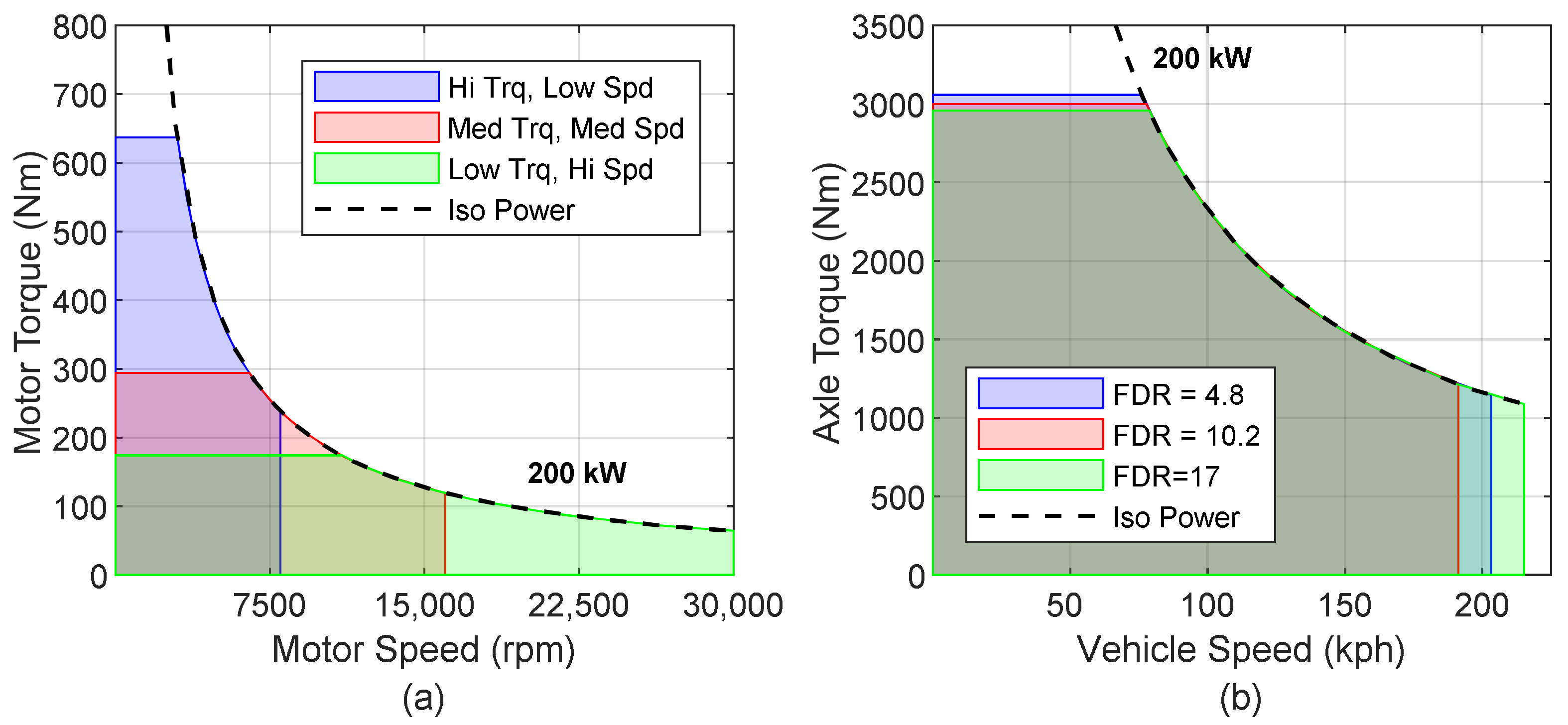
2.1. Electric Machine Performance

The idealized shape of the torque vs. speed curve takes the form of Figure 1a and is irrespective of the specific EM topology. Three different 200 kW EMs are shown in Figure 1a,b, illustrating the diversity in performance possible for a fixed peak power design. These characteristics can be achieved through design of the rotor, stator, type and/or orientation of magnets, or operating voltage and current, etc. [7,8,9,10,17,18,20,21,24,25]. The important takeaway is that for a given maximum power, the torque-speed characteristics can be substantially different. Yet, as Figure 1b indicates translating from EM speed, N E M , and torque, T E M , to vehicle speed, V k p h , and axle torque, T a x l e , respectively, the principal EM curves can be collapsed to achieve nearly identical vehicle level performance through the appropriate selection of the FDR ratio.
The translation between EM and vehicle speeds and torques in Figure 1a,b is governed by two simple relationships. The first is between vehicle speed and EM speed,
V k p h = 2 π N E M r t i r e 3600 60 G R n * F D R 1000 0.377 N E M r t i r e G R n * F D R
where N E M is the electric motor speed in rpm, G R n is the nth transmission gear ratio, and FDR is the final drive gear ratio. In the case of a single speed transmission, the product of G R n * F D R is the only ratio. The torque at the axle propelling the vehicle is related to the electric motor via the same product of transmission gear ratio and final drive ratio, see Equation (2).
T a x l e = T E M G R n * F D R

2.2. Transmission Design Baiscs

The major building blocks that construct the gear train of a TRM to produce a gear ratio and torque transfer path from the prime mover to the axles are summarized in Figure 2. These include parallel axis and planetary gears, transfer chains or belts with fixed tooth count sprockets, or continuously variable diameter variator actuation. Basic GR and speed ratio (SR) equations are provided in Figure 2. For simple and compound planetary gearsets, GR and SR are functionally dependent on nodal configuration and are detailed in Appendix A. Various torque transfer elements can be combined to form the complete TRM, whether as a single ratio or multi-ratio design. Omitted from Figure 2 are the selectable elements used to kinematically determine a fixed or variable ratio state, such as wet or dry clutches, one-way clutches or selectable dog clutches to minimize the scope of the paper. Additional engineering details for selectable shifting elements in TRMs can be found in [56,57,58,59], while those that are specific and innovative to EV TRMs can be found in [39,44,46,47,49]. In Figure 2 and Figure A1 of Appendix A, the variables n and d represent the number of teeth on a gear or sprocket while representing the active diameter of the variator sheave. Section 2.6 provides a review of production, prototype, and proposed EV TRMs that include single and multiple gear ratios, as well as a proposed continuously variable design that are graphical combinations of the elements contained in Figure 2.

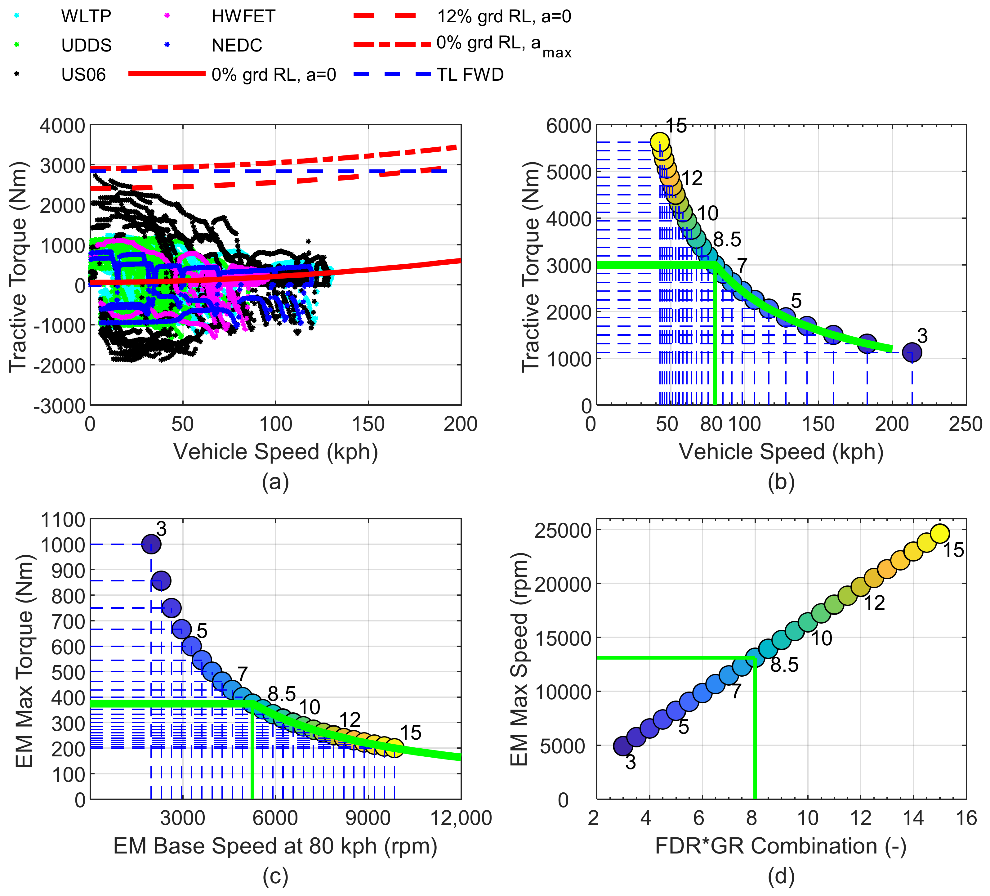
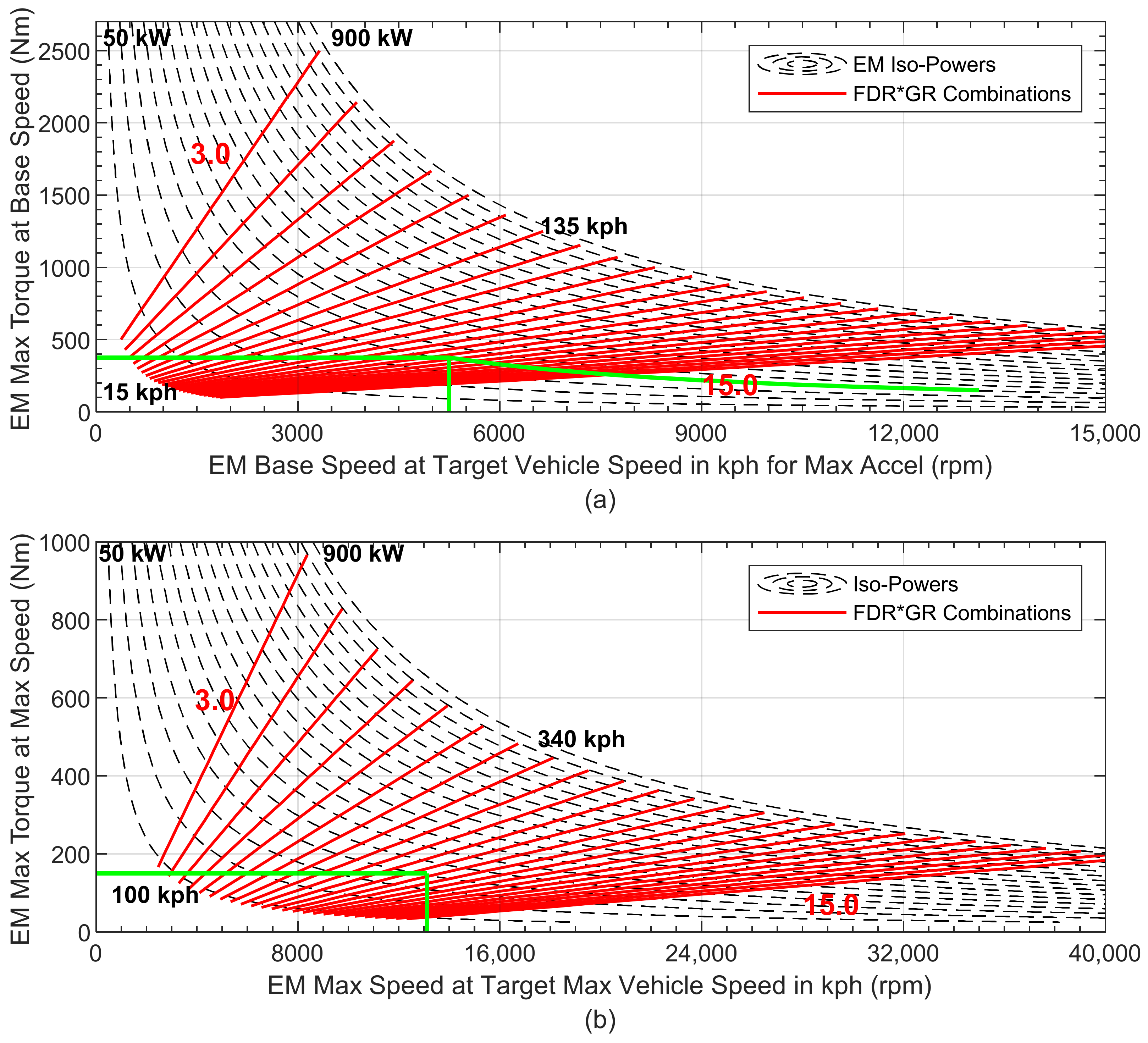
2.3. Propulsion System Requirements and Limitations

The list of performance requirements or targets for any new light—duty mobility product can be extensive, but there are a limited number that make the initial sizing and determination of major performance specifications of the propulsion realizable early in the product development cycle. Table 1 summarizes the basic requirements for propulsion system sizing.
A vehicle’s road load torque often called the tractive torque or road load resistance at the driving axles, T R L , is the resistance the vehicle’s propulsion system must overcome. A zero percent road grade surface under zero acceleration is given via the following equation:
T R L = F 0 + F 1 V + F 2 V 2 r t i r e
where the coefficients F 0 , F 1 , and F 2 represent the static and dynamic rolling resistances of the tires, rotating components of the propulsion system, and the homologated effects of the vehicle’s drag coefficient and atmospheric conditions, respectively. When road grade, m g sin θ , along with vehicle mass and total powertrain inertia, both reflected to the axle, m v e h i c l e r t i r e 2 + I P T , r e f , are considered, see Equation (4), the relationship is applicable to describing the axle torque required during dynamic driving and real world drive cycles.
T R L = F 0 + F 1 V + F 2 V 2 + m g sin θ r t i r e + m v e h i c l e r t i r e 2 + I P T , r e f α a x l e
The vehicle free body diagram of Figure 3 has the critical dimensions that are used to compute the traction limits of the front and rear axles, Equations (5) and (6), respectively, as noted in [60]. Examination of Figure 3 reveals the traction limit of the front axle decreases while the rear axle increases during acceleration. The opposite holds during deceleration. Depending on the performance requirements noted in Table 1, the dimensions of the vehicle’s wheelbase, tire radius, and location of the center of gravity can be tuned to achieve higher traction limits and, thus, greater acceleration performance. Electric vehicle traction limits can benefit from a higher vehicle mass and low center of gravity due to the HV battery. The propulsion system of an EV also lends itself to ideally distributing weight across front and rear axles.
T T L , f r o n t = μ m g cos θ L b + f r h g r t i r e L 1 + μ h g L r t i r e
T T L , r e a r = μ m g cos θ L a f r h g r t i r e L 1 μ h g L r t i r e

2.4. EV Propulsion System Integration Fundamentals

The best way to demonstrate translation of basic performance requirements and targets into an EV propulsion system is to provide an example. A 1628 kg, C-segment passenger car with a tire radius of 0.3234 m, a top speed of 200 kph, an acceleration time of around 7 seconds and the ability to drive up a 12% grade is considered. The vehicle is FWD only and must be capable of driving the major regulatory drive cycles:
  • Worldwide Harmonized Light Vehicles Test Procedure—WLTP
  • New European Driving Cycle—NEDC
  • Urban Dynamometer Driving Schedule—UDDS
  • Highway Fuel Economy Test—HWFET
  • Supplemental Federal Test Procedure—US06.
Figure 4a is a graphical summary of these requirements on a tractive torque vs. vehicle speed (TV) diagram. Steady state, 0, and 12% grade road load curves are indicated along with the maximum acceleration lines, as well as scatter points of operation on all five regulatory drive cycles. Lastly, the front axle traction limit is also shown. A total axle torque output of approximately 3000 Nm will satisfy the requirements mentioned. The crossover point between traction limit and torque required for acceleration occurs at 70 to 80 kph. To optimize performance, the base speed of the EM and total gear ratio of the TRM should converge to this crossover. Thus, the next step is to determine the EM-TRM combination either by clean sheet engineering and design or pulled off the shelf existing components and integrate. For simplicity, assume that a 206 kW EM exists with a base speed of 5250 rpm, max torque of 375 Nm and maximum speed of 13,500 rpm. Assuming a single gear ratio TRM will be sufficient, the only design decision is to select the combination ratio of GR and FDR. As Figure 4b indicates, for a target total tractive torque and vehicle speed corresponding to the acceleration target and traction limit, an 8.0:1 overall ratio combining the GR and FDR is sufficient. In Figure 4b,c, the torque and speed characteristics of the hypothetical off-the-shelf 206 kW EM are confirmed with this choice of overall TRM gear ratio. The exact design of how to achieve this ratio is explored in Section 2.6.
A graphical approach to determining the required torque, speed, and GRs is readily visualized by Figure 5a,b. Continuing the example EV propulsion system integration, Figure 5a,b focus on the EM-TRM selection for the zero to base speed range and at the maximum speed point, respectively. Figure 5a,b contain iso-power curves for the EM (black dashed lines) from 50 to 550 kW in 50 kW steps. Diagonal red lines indicate GR*FDR combinations from 3.0 to 15.0 in 0.5 increments over a range of vehicle speeds. From left to right, the red diagonal lines are denoted with vehicle speeds in kph corresponding to a target maximum acceleration speed ranging from 15 to 135 kph in Figure 5a and maximum vehicle speed range of 80 to 320 kph in Figure 5b.
Figure 5a specifically looks at the determination of the base operating speed point per the target vehicle speed in kph for the maximum acceleration. This is the region of constant, maximum torque of the EM and should be matched to the point at which the traction limit and road load torque curves intersect for desired maximum acceleration. For Figure 5b, the EMs maximum torque at maximum speed can be determined principally through the desired maximum vehicle speed and ensuring that sufficient tractive axle torque is available above the steady state road load line. The green lines in Figure 5a,b indicate the selected GR*FDR combination and corresponding EM torque and speed attributes. The full EM curve is noted in Figure 5a with both constant torque and constant power segments included.
The main takeaway is that a short list of requirements and targets can define the EV propulsion system’s torque, speed, and gear ratio attributes. Further, simple graphical methods can assist the propulsion system design engineer in determining the desired attributes early in the design process.

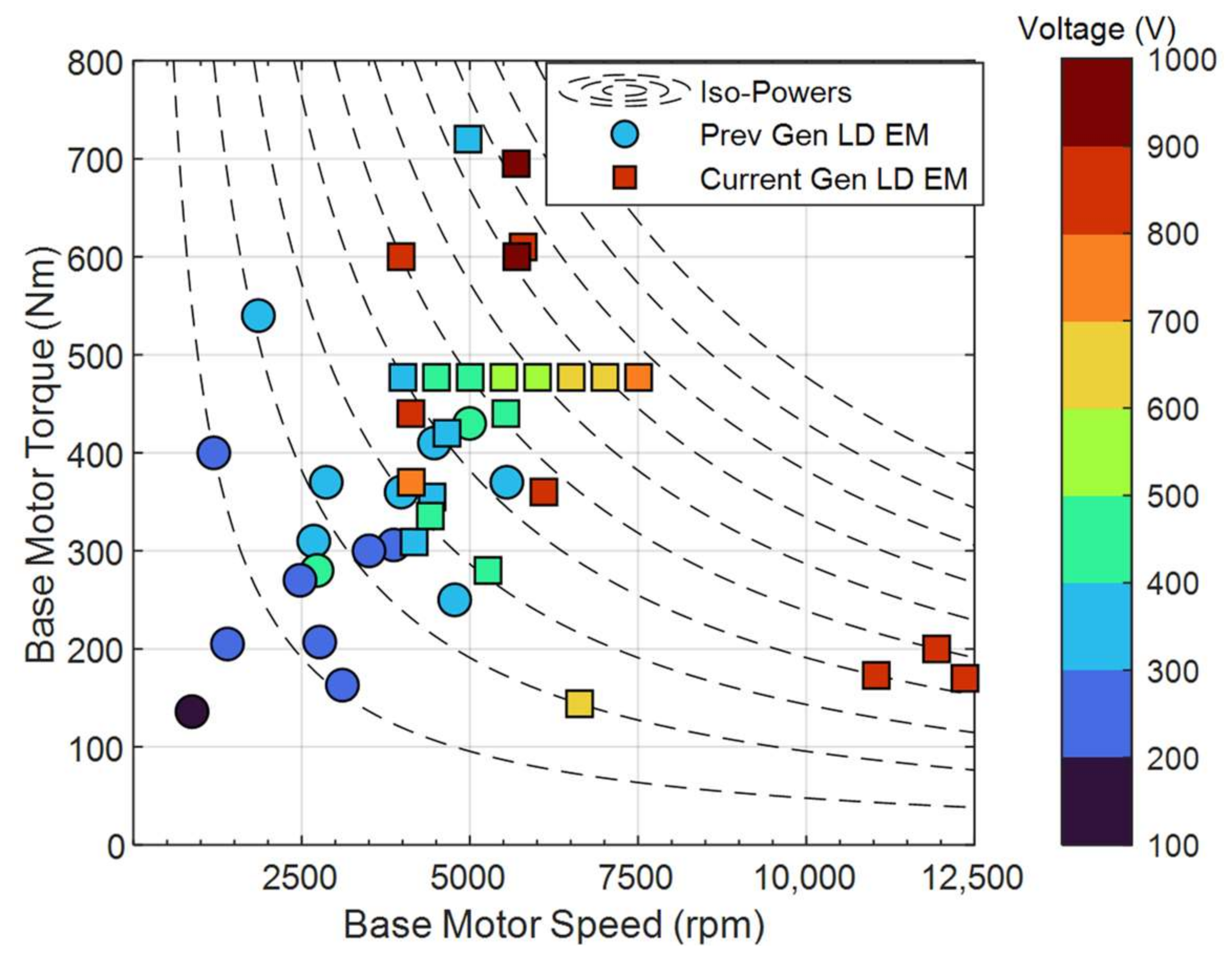
2.5. Review of Electric Motors and Electric Traction Drive Units

A survey of mostly light-duty EMs and ETDUs that are in production, near production, or high probability production prototypes dating from early 2000s to the present, 2023, [7,8,9,13,14,15,16,23,26,27,28,29,30,61,62,63,64,65,66,67,68,69] are summarized in Figure 6, Figure 7, Figure 8 and Figure 9 and focus on various attributes and trends related to EV propulsion system integration. Numerical data contained in Figure 6, Figure 7, Figure 8 and Figure 9 can be found in the supplementary material. Figure 6 concentrates on the maximum power and speed of the EM as a standalone unit. EMs are categorized into two generations of designs, from early 2000s to approximately 2014 (see [7,8,9] for details), and current generation designs from 2015 to the present, [13,14,15,16,23,26,27,28,29,30,61,62,63,64,65,66,67,68,69]. A few EMs designed for heavy duty applications are included for reference as the torque-speed characteristics are quite different. Noted in Figure 6 are the OEM or supplier that designs and manufactures a particular EM, and, in some instances, the vehicle application is included. Current generation designs have increased maximum power, with some designs between 350 and 400 kW. System operating voltage is noted to increase, transitioning from 300–400 VDC to 800+ VDC. The maximum operating speeds of more recent EM designs are commonly at 20,000 rpm, and a few designs have pushed the speed to 30,000 rpm. Lastly, it can generally be observed that a minimum power of 150 kW currently applies to light-duty passenger vehicles designs.
The same EMs contained in Figure 6 are plotted in Figure 7 as gravimetric and volumetric power densities along with select complete EDTUs that includes the EM, TRM, and TPIM. Obviously, EM and ETDU densities continue to increase with improved design and analysis tools, manufacturing techniques, and architectural designs, see [7,8,9]. The best EM designs are approaching 40 to 50 kW/L and approximately 12 to 16 kW/kg, while the best ETDUs are nearing 20 kW/L and 8 kW/kg. Lucid, Koenigsegg, AVL, Porsche, Equipmake, and Cascadia Motion (CM) are at the leading edge of EM technology. NRELs prototype, a rare earth free EM, pushes the kW/L envelope, but falls short of the overall torque capability of rare-earth-contented PMSMs. Including the TRM and TPIM into the packaging equation, Lucid, AVL, and Equipmake are leading all other OEMs or suppliers. Nearly all EMs shown in Figure 6 and Figure 7 are permanent magnet and radial flux machines. The exceptions are Audi’s APA EM and ETDUs, which are IMs [13,15], Koenigsegg’s Quark and Dark Matter EMs and Terrier ETDUs [26,64], which feature permanent magnet machines and operate on a combination of radial and axial fluxes. Yasa’s EMs are axial flux [12,22,23].
Maximum power, speed, and torque density alone do not articulate the EM-TRM integration narrative. An examination of peak torque and base speed is critical in matching the EM and TRM to the performance requirements of the vehicle application. Figure 8 plots the maximum torque from 0 to base speed and the base speed of the light-duty EMs contained in Figure 6 and Figure 7. A quick inspection of the data reveals that from previous to current generation, the base-speed maximum torque point is increasing, consistent with the maximum power trend in Figure 6. A generalized trend can be gleaned from Figure 8 in that nearly all the points can be fit to a curve intersecting at 100 Nm and gaining approximately 0.12 Nm per rpm. There are exceptions, such as the cluster of three points above 10,000 rpm and near 200 Nm, which are recent designs specifically targeting exceedingly high maximum operating speeds, where the balance of the design is speed vs. torque.
Cascadia Motion’s SS250 EM [63] shows up as a string of vertical (Figure 6), diagonal (Figure 7), and horizontal (Figure 8) points and is a result of increasing operating voltage, indicating that performance gains can be realized without any physical modifications to the base machine. Obviously, the mechanical design of the EM must be able to accommodate such a change in operating voltage. The torque-speed capability of the CM SS250 EM, both peak and continuous, are presented in Figure 9a, showing that increasing the operating voltage pushes the base speed higher while maintaining the same maximum torque. Alternatively, the influence of EM design is represented in Figure 9b and Table 2, pointing to the major differences in radial flux PMSM [15], radial flux IM [61], and axial flux permanent magnet (AFPM) [23]. All EMs in Figure 9b have nearly identical peak power, base speed, and maximum torque ratings. AFPM designs, however, generally have only moderate maximum operating speeds. It should be noted that PMSM can have higher maximum speeds than the 150 kW variant noted in Figure 9b, see [61] for example. A bit more insight though can be gleaned from Table 2 about packaging volume, mass, and rotor dimensions listed. Tradeoffs in diameter, length, and mass are apparent, but a general observation is that an AFPM can provide an advantage in axially packaging while delivering high torque density. Numerous other tradeoffs exist between EM topologies beyond what is communicated in Figure 9 and Table 2, including cost, thermal management, efficiency, and manufacturing.

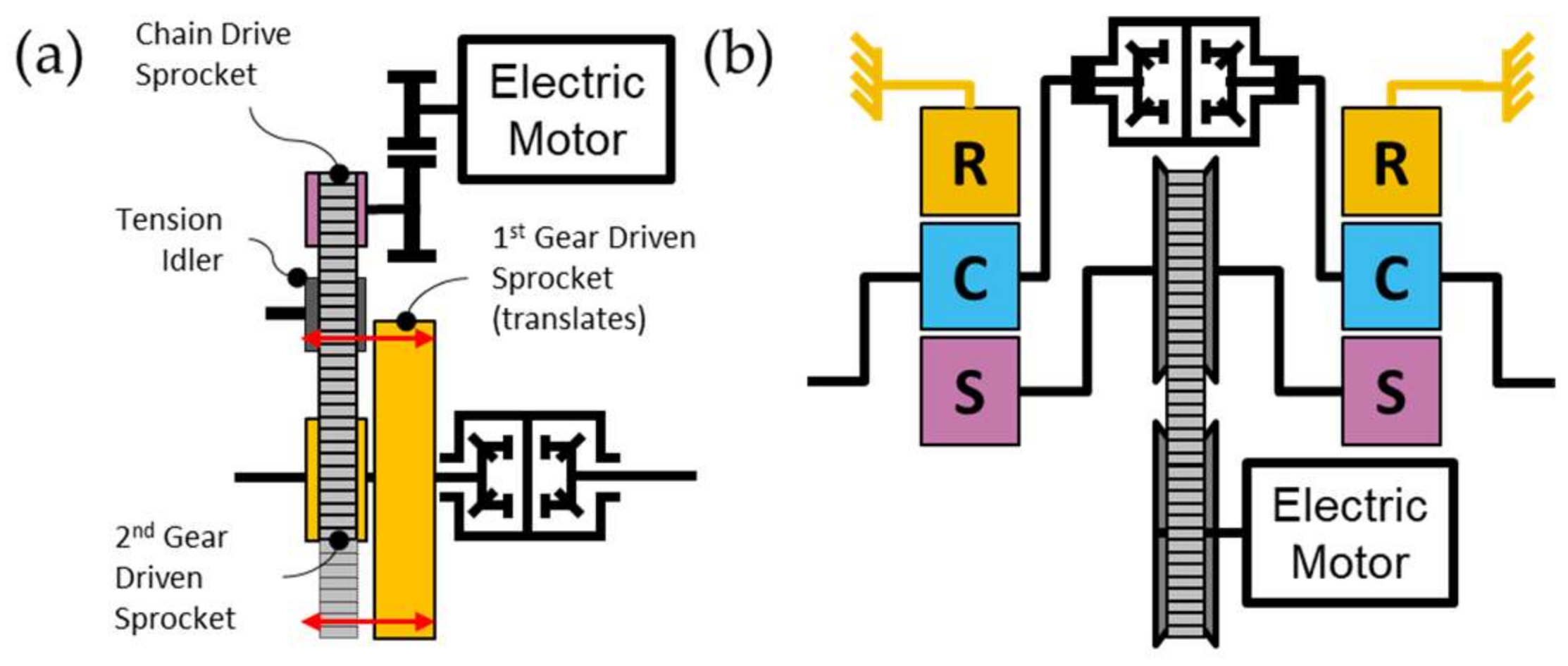
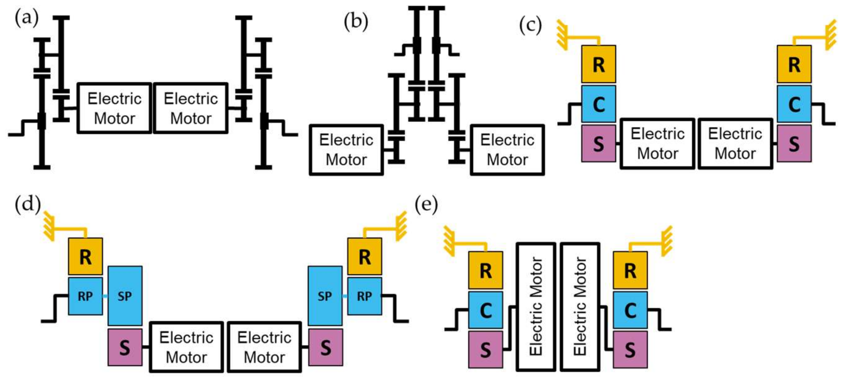
2.6. Review of Electric Vehicle Transmissions

Transmission engineering for EVs has not evolved to the complexity of current conventional powertrains. However, there has been significant engineering effort and diversity in the single and multi-speed TRMs featured in current, projected, or proposed EV propulsion systems. This section will highlight these designs with graphical depictions derived from the TRM fundamental building blocks presented in Figure 2.
Figure 10a–f features single speed, single EM ETDU that exist and are typically the most common. Figure 10a features the layshaft, parallel axis gear design in which the differential can either be offset or co-axial with the EM rotation axis. This design is by far the most common EM-TRM combination with an overall ratio, G R * F D R , in the range of 6:1 to 10:1 and can be found in numerous light-duty vehicles as either FWD, RWD or AWD, see [42]. Planetary gears can be used similarly as noted in Figure 10b to create a single speed design, with a much more limited overall ration range of 2:1 to 5:1 when compared to layshaft designs. Planetary and parallel axis gears, as in Figure 10c, can be coupled to achieve an overall ratio range from 6:1 to 11:1. Two simple planetary gearsets can be combined, see Figure 10d, to achieve a larger overall ratio than single set. A simple planetary with stepped pinions, as shown in Figure 10e, can be employed and achieve upwards of a 10:1 overall ratio without much engineering effort. The ETDU of Figure 10f with a single EM is a unique design, see [29], in which the differential is placed directly in connection with the EM and two independent simple planetary gear reducers are used outboard, each with a ratio of approximately 7:1.
A second EM and TRM can be added to the ETDU to boost the torque output of the single speed ETDU without the use of an overall larger gear ratio or the use of a multi-speed TRM. This approach preserves the top speed of the ETDU at the expense of double the EM and TRM content. An example of single speed, dual EM ETDUs are shown Figure 11a–e, with the EMs inboard of the TRM gearing in Figure 11a,c–e. The EMs are outboard of the TRM gearing in Figure 11b. The graphical depictions of the dual EM ETDUs are just combined and mirrored single EM ETDUs from Figure 10 as a single unit. All dual EM ETDUs omit the differential, and there is no direct coupling of the EMs to transmit torque from one axle to the other. The unique feature of the dual EM ETDU in Figure 11e is that the EMs are axial vs. radial flux permanent magnet machines, thus, the orientation changes.
To reduce the EM and TRM content, additional multiple GRs are introduced into the ETDU. To date, there are limited multi-speed EV TRM designs that are in production. Figure 12a–f is a graphical summary of two speed configurations that are principally built with simple planetary gearsets and two clutches, Figure 12a–c, while more complex configurations are noted in Figure 12d–f. It is important to highlight that the two speed ETDUs shown in Figure 12e,f are current production designs utilized in light-duty passenger vehicle applications. Figure 12e is utilized as a RWD ETDU to supplement a FWD parallel hybrid electric propulsion system and is thus not an exclusive EV ETDU, see [33,34] for more details. Figure 12f is utilized in a light-duty performance car on the rear axle and employs a combination of parallel axis and compound planetary gears to reduce EM speed. The compound planetary gearset contains two shift elements, a rotating wet clutch and a grounding mechanical dog clutch [35,36,69]. The two speed TRMs in Figure 12 can achieve a first gear ratio upwards of 16:1, namely configurations d, e, and f.
Layshaft, dual clutch transmissions (DCTs) are composed of parallel axis gears and synchronizers are an alternative to the planetary gearset multispeed designs noted in Figure 12. Two and three speed DCT speeds have been proposed as production implementations with the arrangements noted in Figure 13a–d, with two speed variants in a and b, and three speed configurations in c and d. The DCT module of Figure 13a [44] is a proprietary arrangement in which the dual clutching mechanisms have not yet been disclosed publicly in literature or patents, while the DCT modules in Figure 13b–d are the more traditional nested, inner, outer, diameter arrangements. The layshaft gearing enables more flexibility and tuning of the gear ratios desired for a particular application, but in general can achieve similar overall gear ratio results of Figure 12.
TRM designs that break with traditional step-gear technology are noted in Figure 14, with a two speed transfer chain design that is analogous to a pedal bicycle derailleur [46], in Figure 14a, and a continuously variable transmission (CVT) paired with simple planetary gear reducers coupling the differential [47], in Figure 14b. Both designs achieve multiple speeds, but with a vastly different mechanization and actuation of the ratio changing process.

2.7. Transmission Design and Parasitic Losses

With any TRM design, the minimization of the parasitic losses is important in any application, but for EV propulsion systems as it directly correlates to range and potential increases in battery capacity to achieve vehicle level performance requirements. For single or multi-speed EV TRM designs, the gears, bearings, and shafts must work over a wider speed range than an ICE application, sometimes out to 30,000 rpm. This can pose certain engineering challenges to maintain lubrication and durability, while keeping the drag torque low. Although the topic of TRM losses can be quite detailed and is specific to the TRM architecture, hardware selection and control strategy for hydraulics and lubrication, three basic relationships can be used in place of detailed software, such as Romax, MASTA, or KISSsys for example, to analyze the sufficiency of a design for losses. A simple torque loss or efficiency calculation for a TRM can be performed with the following three relationships: (1) Tuplin’s gear mesh efficiency [70], as summarized using Equations (7)–(9), (2) oil churning losses for gears or rotating components partially submerged in oil given via Equation (10) with details of S m and C m in Appendix B, [71,72,73] and (3) drag torque associated with unapplied shifting clutches, generalized in Equation (11) for wet shifting clutch [74,75].
η m e s h = 1 P l o s s , c o e f f * P m e s h , r a t i o
P l o s s , c o e f f = 0.2 1 N 1 , t e e t h ± 1 N 2 , t e e t h
P m e s h , r a t i o = N 1 , t e e t h N 2 , t e e t h
T c h = 1 2 ρ ω 2 S m R 3 C m
T d r a g = n s u r f π μ r o 4 r i 4 Δ ω s l i p 2 h
The summation of the torque losses associated with gear mesh, oil churning from rotating components, and unapplied shifting elements was applied to two ETDUs depicted in Figure 10a and Figure 12f. Foregoing a detailed analysis, the impacts on TRM design on efficiency spanning the range of EM torque and speed for each application can be illustrated. The TRM of Figure 10a is a single speed layshaft design spinning to almost 9000 rpm and torque up to 400 Nm. The black shaded region in Figure 15 indicates the approximate area of efficiency during normal oil operating temperatures for an overall gear ratio of 7.05:1. The peak efficiency approaches 99% at elevated torques and low speeds, dropping to around 97% at maximum speed. The two speed TRM from Figure 12f, contains more gear content and subsequent meshes while incorporating two shifting elements, B1 and C1. For simplicity, Equation (11) is applied to the B1 clutch with an assumed scalar of 0.25 to approximate the losses of mechanical dog clutch when not activated in second gear. Clutch C1 is a rotating wet clutch, not active in first gear. As noted in Figure 15, for the first gear ratio of 15.5:1 shaded in green, there is a lower efficiency than the second gear ratio of 8.05:1 shaded in red. For this application, the EM can spin to 16,000 rpm and has a maximum torque of 600 Nm. It is obvious that prolonged operation in first gear will be disadvantageous for maximum driving range. Although the second gear ratio of Figure 12f is close to that of the gear ratio of Figure 10a, the combination of additional reduction gearing and higher maximum motor speed results in lower efficiency at higher vehicle speeds. However, there is significant overlap under normal roadways speeds.
From the analysis of Figure 15, there are clear and tangible benefits to a focused approach when engineering the EV TRM. This includes all aspects; however, the type of gears, bearings, lubricants, seals, and shifting elements are critical. The engineering team responsible for the TRM design and execution must analyze at the full propulsion system level to achieve the best performance as shown in [52,53,54].

3. Results

A basic EV propulsion system integration exercise will be applied to three light-duty EV applications in this section: (1) economy passenger car, (2) performance car, and (3) truck, commonly referred to as a pickup truck in the North American market. The integration analysis will look at the baseline vehicle and comparable alternative variants of EM-TRM combinations. The examples chosen have EM and TRMs represented from Section 2. Electric motor performance curves can be found in the supplementary material.

3.1. Light-Duty, Economy Passenger Car

The baseline vehicle and propulsion system parameters for this application are provided in Table 3, see [12]. The EM performance curve is the PMSM in Figure 9b, the TRM configuration is shown in Figure 10a, and the efficiency is contained in Figure 15 as the black shaded region. The aim of the integration analysis for this application is to explore the potential for a two speed TRM to improve performance without affecting energy consumption and efficiency. Other EM-TRM combinations are also investigated to determine if any appreciable efficiency gains and reduced energy consumption are possible.
The baseline economy car’s maximum and minimum axle torque envelopes, FWD traction limit, zero grade road load, 12% grade road load, zero grade maximum acceleration torque, and scatter points of operation on five major regulatory test cycles are contained in Figure 16. The baseline propulsion system is noted to be slightly above the traction limit, maximum acceleration line, 12% grade, and all the scatter points of the drive cycles, indicating that the EM-TRM combination is adequately sized. The peak acceleration of the vehicle will sustain out to approximately 70 kph with maximum vehicle speed around 150 kph.
Next is to examine whether the propulsion system will benefit from a second gear ratio or other EM-TRM variants. A thorough optimization, e.g., [52,53,54], could be performed for any EM-TRM variant to determine GRs; however, a simple approach was chosen to illustrate the process. Second GR was selected as half that of first gear ratio, and all new EM-TRM variants of the first gear ratio were selected to match that of the baseline vehicle. Four EM-TRM variants were selected from the available EMs plotted in Figure 6 and Figure 7. Variants 1, 2, and 3 are radial flux PMSM, and variant 4 is an AFPM. The TRM shifting assumption was kept simple such that the first gear was only utilized when the overall propulsion system efficiency was higher than in second gear or operation in second gear exceeded the continuous operating limit of the EM. This limit was assumed to be roughly 70% of the peak torque rating.
The EM peak torque curves and efficiency contours greater than 80% are plotted in Figure 17 with single speed TRMs in the top row and two speed TRMs in the bottom row. Figure 17 is annotated with the details of the gear ratios, DC high voltage rating, and peak power. The red, GR1, and blue, GR2, scatter points represent all five regulatory drive cycles combined. EM variants 1, 2, and 4 have higher peak torques with similar maximum speeds, whereas variant 3 has a lower peak torque and much higher maximum speed when compared to the baseline EM. EM variants 2 and 3 are identical but have different DC operating voltages, consistent with Figure 9a. The two speed TRM variants reduce the speed of the EM relative to driving all five of the drive cycles as indicated with the scatter points.
The synergy can increase the overall propulsion system efficiency and reduce parasitic energy losses by lowering the operating speeds of the EM and TRM. The details are communicated in Figure 18 as total energy losses in kWh for the EM, TRM, and total propulsion system traversing all five drive cycles, a total of 75.6 km. The left column of Figure 18 shows that universally TRM losses decrease with a second gear ratio whereas EM loss reduction is a mixed result, depending on where the operating point resides relative to the efficiency contours. Refinement and optimization of the shift pattern could potentially yield further reductions in EM energy losses but would most likely be minor contributions. The decrease in total ETDU energy losses is dominated by TRM efficiency gains. The best alternative EM-TRM combination from Figure 17 and Figure 18 is variant 4, a high max torque, low max speed AFPM design that pairs with a low overall ratio two speed transmission. The right column of plots in Figure 18 are distribution plots of cumulative time spent operating within a particular range of efficiency for the EM (top), TRM (middle), and overall EV propulsion system (bottom). The results highlight that even a limited search of EM-TRM matching with suboptimized GRs and shifting patterns can produce an EV propulsion with improved energy sufficiency. The ability of TRM to put the EM into the operation of high efficiency contours while itself operating with low losses is a fundamental conclusion. The selection of the GRs can be relatively straightforward, but the engineering of the TRM for low losses is a major challenge. For the 75.6 km combined drive cycles, the margin of energy savings for a two speed TRM is slightly less than 1 kWh or roughly 0.01 kWh/km. When compared to the baseline single speed propulsion system for this application, additional TRM content cannot result in parasitic losses higher than these guidelines.

3.2. Light-Duty Performance Car

The AWD performance car baseline parameters are listed in Table 4 [35,36,69], with understandably different requirements and criteria than the economy car and, specifically, greater expectations for acceleration and top vehicle speed.
The capability of the AWD performance car’s propulsion system relative to requirements and targets is depicted graphically in Figure 19. The FWD ETDU is capable of meeting regulatory drive cycles which can be representative of real-world driving, suggesting that the EM in RWD ETDU can be decoupled mechanically during normal driving conditions to reduce parasitic losses, improving energy consumption and range. The front axle has a torque that slightly exceeds the traction limit of the axle at 75 kph and the ability to meet road load up to 275 kph without RWD support. The rear ETDU in first gear, GR1, exceeds the rear traction limit by 4000 Nm, providing a max torque of 50 kph, but it can only be utilized up to 143 kph before requiring a shift to second gear, GR2. In GR2, torque output is slightly below the rear axle limit from 0 to 100 kph and at maximum vehicle speed is 1000 Nm over road load. The propulsion system can bias more torque output to the rear axle, a known desired dynamics attribute of a performance car and a customer expectation. The integration details of this AWD EV propulsion system enable near maximum possible acceleration from 0 to 100 kph and, with the selected gearing, achieve a 260 kph top speed.
Competitor AWD performance car EV propulsion systems applied to the base vehicle described in Table 4, are compared in Figure 20. Two competitor vehicles were selected whose EMs are in Figure 6 and Figure 7, and the TRMs are depicted in Figure 10. All three propulsion system comparisons are AWD and use single EM ETDUs. Only the rear ETDU of the baseline vehicles has a two speed TRM. The EM performance curves are at the top of Figure 20, blue FWD EM and orange RWD EM, while AWD tractive effort, AWD traction limit, and road load are in the bottom row of plots. Figure 20a,b use EMs with different peak power and torque on front and rear axles, whereas Figure 20c uses identical EMs and GRs. Both Figure 20b,c meet or exceed the total traction limit of the vehicle, but what is not communicated is that the front ETDU tractive torque capability will exceed the front axle traction limit and, thus, will result in slower acceleration. The GR selections of Figure 20b could be reduced to bring traction torque down to the traction limit and increase the maximum vehicle speed from 250 kph back up to the vehicle base of 260 kph. For the EV propulsion system in Figure 20c, the vehicle top speed is more than 300 kph due to the higher EM maximum speed of 20,000 rpm and use of lower GRs. The GRs could be tuned to alleviate the traction issue on the front axle and boost the rear axle to obtain the maximum vehicle speed closer to that of the baseline at 260 kph. Overall, both competitor EV propulsion systems with single speed TRMs meet the requirements of the baseline vehicle.
Alternative EM-TRMs are explored in Figure 21a–c with EM performance curves in the top row of plots, noting FWD EM in blue and RWD EM in orange. The number of EMs and peak power are indicated. Multi-speed TRMs are analyzed with total tractive effort, AWD traction limit and road load plotted for the GRs annotated in the plots. Figure 21a,b both utilize variants of the CM SS250 EM [63], while the three EMs in Figure 21c are all 250 kW AFPM machines by Koenigsegg, the Quark, see Figure 6 and Figure 7 [26]. For ETDU combinations in Figure 21, the AWD EV propulsion system characteristics can match that of the baseline vehicle and exceed the maximum vehicle speed of 300 kph. However, the total peak power and, thus, current draw from the battery may be a concern, even with the system’s operating voltage at 700 to 800 VDC. The base vehicles total power is 560 kW, the competitors in Figure 20b,c are 585 and 716 kW, respectively. Recent three motor EV variants are pushing the limit to 1000 kW as battery capabilities improve along with system operating voltages pushing towards 1000+ VDC.

3.3. Light-Duty Truck

Light-duty trucks have significantly more mass and road load resistance than passenger cars due to their HV battery packs with capacities. They have a unique blend of requirements including high launch torque and acceleration, moderate maximum vehicle speed and the ability to haul and tow a substantial payload with the best possible efficiency. Two production light-duty trucks are explored: (1) a dual EM, AWD EV that is equivalent to the conventional ICE version in all respects and (2) a three EM performance off road, rock crawler. Table 5 contains the vehicle parameters, see [76,77] for more details.
For both vehicles the front and rear EMs are nearly identical, as shown in Figure 22a,b, noting that Figure 22b has a dual EM rear ETDU. Both vehicles only use single speed TRMs in all the ETDUs. One benefit of the additional mass is increased traction limits on both axles, an enabler for the impressive 4 s or less 0–100 kph acceleration time. The tractive torque for Figure 22a is 2500 Nm below the traction limit while that of Figure 22b is right up to the traction limit at 16,500 Nm. The larger rolling radius tires of the light-duty truck applications mean a larger numerical overall GR is possible to multiply EM torque and still achieve the maximum vehicle speed requirement of 180 kph. A multi-speed TRM might be useful in aiding vehicle launch during towing or hauling while also lowering the EM and TRM operating speed in second gear under normal driving speeds to improve efficiency; however, further analysis is required to explore these interactions.

4. Discussion

The initial process of sizing and integration of an EV propulsion system based upon a limited set of simple requirements was shown on three production EV applications. Each application utilized a different EM with varying levels of performance metrics primarily with single speed TRM with GRs between 7:1 and 13:1. From an industrial perspective, the prospect of a single EM paired with a scalable TRM with tunable GR applied across multiple vehicles, from an economy car to light-duty trucks, can be key to economy of scale. This approach is evidenced by several OEMs recent announcements or product releases [65,76,77]. In applications where axle torque is deficient relative to the performance requirements, a second EM is typically added to the rear ETDU [16,29,30,62,78], rather than a multispeed TRM as for most EVs. In certain vehicle applications, particularly performance cars that require a high maximum vehicle speed and substantially large tractive torques to 100 kph, multi-speed TRM have an engineering justification [33,34,35,36]. The enterprise approach of utilizing a single EM design for the three light-duty EV applications is presented in Figure 23 for (a) economy passenger cars, (b) performance cars, and (c) trucks. The basic performance requirements/targets are satisfied utilizing a 225 kW PMSM EM with 15,000 rpm max speed and 460 Nm peak torque. A single speed TRM with GRs varying between 6:1 and 13:1 depending on the EV and EDTU configuration on the front and rear axles. Utilizing a single EM ETDU for the EV truck, Figure 23c, would most likely require a unique TRM design to achieve a GR of 13:1 car EVs, negating commonality. Instead, the use of a dual EM rear ETDU facilitates a smaller numerical GR, most likely making the TRM design common, enabling a scalable design across the range of EV applications. The GR range of 6:1 to 9:1 can easily be accommodated through a single speed, two-stage parallel axis design like that depicted in Figure 10a which has positive design attributes for efficiency considerations. The 255 kW EM in Figure 23 is part of an EM set strategy reported by [65], stating their complete future EV product portfolio can be powered by various configurations of three EMs, 62 kW, 180 kW, and 255 kW, and TRMs with tunable GRs and scalable torque capacity. This approach can greatly simplify the engineering, complexity, and cost of EV propulsion systems for full vehicle line OEMs and is supported by the simple analysis shown in Figure 23.
The 255 kW EM machine shown Figure 23 could easily be constructed as an IM, an SRM, or any other type of EM, but as prior works [10,24,25] conclude, PMSM represent a more suitable selection than IM or SRM for EVs as peak efficiency and the location of the efficiency contours matter most to help minimize battery size for a desired range. SRM EM technology is a desirable architecture since there is no rare earth materials representing a lower penalty in terms of cost and raw materials availability but can be a negative on controls complexity, torque ripple, and drive quality [19]. However, recent advances in SRM that combine the benefits of axial flux and optimization for torque ripple, see [18], may overcome these deficiencies and displace PMSM as the dominant EM type for light-duty EV propulsion. With respect to EM topology, at the current state in 2023, PMSM dominates the EV propulsion landscape as indicated by [5], followed by IM, then PMBLDC, and finally a few applications utilizing wound synchronous rotor (WSRM) and synchronous-reluctance-type EMs. As [5] discusses in their benchmarking work, there are tradeoffs associated with all types of EM architectures, but PMSM, IM, and SRM are most attractive for volume production due to cost, efficiency, reliability, and performance. PMBLDC is an attractive choice for torque density but can be negative on cost and efficiency. This conclusion further backed through an examination of model year 2023 and 2024 new EVs available for sale in the United States. Pulling EM data from EPAs public database [79], and accounting for all possible EV models and subvariants available, 217 in total, the EM features in these platforms are composed of nearly 88% synchronous and approximately 12% asynchronous machines. The EPAs database also contains specific EM topology, and accounting for all EMs within a given EV, there are 405 total EMs within the 217 EVs, where 63.7% are PMSM, 11.6% are IM, 18.3% are externally excited synchronous motors (EESM), a BMW design that is a brushed AC machine, 3.5% are PMBLDC, and 3.0% are permanent magnet synchronous reluctance motors (PMSRM). The PRSRM is a unique EM for light-duty EVs and is the principal EM in all rear ETDU of Tesla’s EVs. Even though synchronous EM variants, particularly PMSM, are more numerous and appear in more EV applications, asynchronous EM variants appear on the road in higher numbers due to more significant sales volume of only a few select EVs. Most IMs are found in the front ETDU of all AWD Tesla models, with Tesla owning roughly 67% share of the EV market in the United States in 2022, [80].
Multi-speed transmissions in EVs are primarily utilized to enhance performance [4,16,35,36,42,62], but they also have the potential to improve efficiency and, thus, range as is commonly reported by the supplier or OEM. However, the additional content in the TRM required to achieve a suitable multispeed design can negatively impact the overall system efficiency. In [54], artificial neural network learning was applied to a comprehension electrical-mechanical model of two speed EV propulsion system to produce around 1.7% energy reduction, which is in alignment with the simplistic energy and TRM shift analysis performed in this study, as well as the simplified approach reported by [52].
Overall, it is unlikely from an engineering perspective that the degree of market penetration for multi-speed TRM for EV propulsion systems will materialize to the degree as ICE powertrains. This conclusion is especially true with the trends noted in Figure 6, Figure 7 and Figure 8 as the power, torque, and speed capabilities for EMs will continue to increase with decreasing packaging volumes and increasing operating voltage. Thus, the need to provide multiple gear ratios to achieve the blend of launch, acceleration, and vehicle top speed is reduced to needing a singular option. The development of a select few EMs, a torque scalable single speed TRM with flexibility to adjust the overall gear ratio and ability create a dual EM rear axle ETDU, OEMs should be able to enterprise their electric propulsion system hardware across vehicle applications from compact cars to large light-duty trucks.

5. Conclusions

This paper reviewed the state-of-the-art EM and TRM system technologies for light-duty electric vehicles at the time of writing in 2023. Production, near production, or prototype EMs were summarized from a peak power, maximum speed, maximum torque, volumetric, and gravimetric power densities, and the influence of increasing operating voltages and the various architecture and design types were explored, including their impact on performance. Single and multi-speed TRMs available in production, prototype, or proposed for production were also summarized, noting that few multi-speed designs are in production for light-duty vehicles as of 2023. A high-level view of EV propulsion system integration and selection of the EM and TRM per a simple and concise list of requirements was illustrated with three distinctly different vehicle applications. Through the review of the current available hardware and vehicle integration examples, the trend of increasing the high voltage and design optimization of the electric motor is eliminating the need for significant engineering effort towards creating multi-speed transmission all but for a few select and specialty light-duty vehicles, such as performance cars. The basic matching process of the EM and TRM were explored for three EV applications finding that for all but high-performance vehicle applications, single speed TRMs are sufficient, and it is more likely that a second EM will be added to the rear ETDU to increase tractive torque rather than the implementation of a multi-speed TRM with a single EM. If a multi-speed transmission is sought, the energy savings margin per km is approximately 0.01 kWh. This number directly correlated to any increase in parasitic losses from added TRM content and gains in EM operating point efficiency. With the advancements in torque density and packaging of EMs, it is likely that OEMs and tier 1 suppliers can provide a limited EM offering in terms of speed–torque characteristics coupled with single speed TRMs with flexible and scalable gearing to meet the needs of the entire range of light-duty EV applications.

Supplementary Materials

The following supporting information can be downloaded at: https://www.mdpi.com/article/10.3390/vehicles5030065/s1, Microsoft Excel file containing numerical electric motor benchmarking and performance curves for Figure 6, Figure 7, Figure 8, Figure 9, Figure 16, Figure 17, Figure 19, Figure 20, Figure 21 and Figure 22.

Funding

This research received no external funding.

Data Availability Statement

The data presented in this study are available in a supplementary file posted with this paper and contains electric motor benchmarking and performance curves.

Conflicts of Interest

The authors declare no conflict of interest.

Abbreviations

AFPMAxial Flux Permanent Magnet
AWDAll Wheel Drive
CVTContinuously Variable Transmission
DCDirect Current
DCTDual Clutch Transmission
EMElectric Motor
EESMExternally Excited Synchronous Machine
ETDUElectric Traction Drive Unit—Electric Motor + Transmission
EVElectric Vehicle
FDRFinal Drive Ratio
FWDFront Wheel Drive
GRGear Ratio
HVHigh Voltage
ICEInternal Combustion Engine
IMInduction Machine
NRELNational Renewable Energy Laboratory
OEMOriginal Equipment Manufacturer
PMSMPermanent Magnet Synchronous Machine
PMSRMPermanent Magnet Synchronous Reluctance Machine
RWDRear Wheel Drive
SRMSwitched Reluctance Machine
TPIMTraction Power Inverter Module
TRMTransmission
VDCVoltage Direct Current

Appendix A

Planetary gear lever ratio summary of all permutations of input, output, and constraint nodes. Indicated for simple and compound planetary gearsets with exemplary gear tooth counts. Depictions and approach adapted from [81,82,83].
Figure A1. Summary of simple (left) and compound (right) planetary gearset lever diagrams and all permutations of input, output, and constraint for gear ratio, exemplary tooth counts provided.
Vehicles 05 00065 g0a1

Appendix B

Graphical summary of stepwise calculation of oil churning losses as proposed by [71,72,73] for rotating components partially submerged in oil sump.
Figure A2. Summary of oil churning loss calculations for partially submerged rotating components, total submerged surface area, Sm, and dimensionless drag coefficient, Cm.
Vehicles 05 00065 g0a2

References

  1. Conway, G.; Joshi, A.; Leach, F.; Garcia, A.; Senecal, P.K. A Review of Current and Future Powertrain Technologies and Trends in 2020. Transp. Eng. 2021, 5, 100080. [Google Scholar] [CrossRef]
  2. International Energy Agency. The Role of Critical Minerals in Clean Energy Transitions. 2021. Available online: https://www.iea.org/reports/the-role-of-critical-minerals-in-clean-energy-transitions (accessed on 28 March 2023).
  3. Castelvecchi, D. Electric Cars and Batteries: How Will the World Produce Enough? Nature 2021, 596, 336–339. [Google Scholar] [CrossRef] [PubMed]
  4. Machado, F.A.; Kollmeyer, P.J.; Barroso, D.G.; Emadi, A. Multi-Speed Gearboxes for Battery Electric Vehicles: Current Status and Future Trends. IEEE Open J. Veh. Technol. 2021, 2, 419–435. [Google Scholar] [CrossRef]
  5. El Hadraoui, H.; Zegrari, M.; Chebak, A.; Laayati, O.; Guennouni, N. A Multi-Criteria Analysis and Trends of Electric Motors for Electric Vehicles. World Electr. Veh. J. 2022, 13, 65. [Google Scholar] [CrossRef]
  6. Mądziel, M.; Campisi, T. Energy Consumption of Electric Vehicles: Analysis of Selected Parameters Based on Created Database. Energies 2023, 16, 1437. [Google Scholar] [CrossRef]
  7. Chowdhury, S.; Gurpinar, E.; Su, G.-J.; Raminosoa, T.; Burress, T.A.; Ozpineci, B. Enabling Technologies for Compact Integrated Electric Drives for Automotive Traction Applications. In Proceedings of the 2019 IEEE Transportation Electrification Conference and Expo (ITEC), Detroit, MI, USA, 17–19 June 2019; pp. 1–8. [Google Scholar] [CrossRef]
  8. Agamloh, E.; von Jouanne, A.; Yokochi, A. An Overview of Electric Machine Trends in Modern Electric Vehicles. Machines 2020, 8, 20. [Google Scholar] [CrossRef]
  9. Husain, I.; Ozpineci, B.; Islam, S.; Gurpinar, E.; Su, G.-J.; Yu, W.; Chowdhury, S.; Xue, L.; Rahman, D.; Sahu, R. Electric Drive Technology Trends, Challenges, and Opportunities for Future Electric Vehicles. Proc. IEEE 2021, 109, 1039–1059. [Google Scholar] [CrossRef]
  10. Yang, Z.; Shang, F.; Brown, I.P.; Krishnamurthy, M. Comparative Study of Interior Permanent Magnet, Induction, and Switched Reluctance Motor Drives for EV and HEV Applications. IEEE Trans. Transp. Electrif. 2015, 1, 245–254. [Google Scholar] [CrossRef]
  11. Woolmer, T.J.; McCulloch, M.D. Analysis of the Yokeless And Segmented Armature Machine. In Proceedings of the 2007 IEEE International Electric Machines & Drives Conference, Antalya, Turkey, 3–5 May 2007; pp. 704–708. [Google Scholar] [CrossRef]
  12. Schneider, E.; Fickel, F.; Cebulski, B.; Liebold, J. Highly Integrative and flexible Electric Drive Unit for Electric Vehicles. ATZ Worldw. 2011, 113, 10–15. [Google Scholar] [CrossRef]
  13. Hawkins, S.; Holmes, A.; Ames, D.; Rahman, K.; Malone, R. Design Optimization, Development and Manufacturing of General Motors New Battery Electric Vehicle Drive Unit (1ET35). SAE Int. J. Altern. Powertrains 2014, 3, 213–221. [Google Scholar] [CrossRef]
  14. Jurkovic, S.; Rahman, K.; Patel, N.; Savagian, P. Next Generation Voltec Electric Machines; Design and Optimization for Performance and Rare-Earth Mitigation. SAE Int. J. Altern. Powertrains 2015, 4, 336–342. [Google Scholar] [CrossRef]
  15. Liu, J.; Anwar, M.; Chiang, P.; Hawkins, S.; Jeong, Y.; Momen, F.; Poulos, S.; Song, S. Design of the Chevrolet Bolt EV Propulsion System. SAE Int. J. Altern. Powertrains 2016, 5, 79–86. [Google Scholar] [CrossRef]
  16. Doerr, J.; Attensperger, T.; Wittmann, L.; Enzinger, T. The New Electric Axle Drives from Audi. ATZelektronik Worldw. 2018, 13, 16–23. [Google Scholar] [CrossRef]
  17. Raminosoa, T.; Wiles, R.; Cousineau, J.E.; Bennion, K.; Wilkins, J. A High-Speed High-Power-Density Non-Heavy Rare-Earth Permanent Magnet Traction Motor. In Proceedings of the 2020 IEEE Energy Conversion Congress and Exposition (ECCE), Detroit, MI, USA, 11–15 October 2020; pp. 61–67. [Google Scholar] [CrossRef]
  18. Ajamloo, A.M.; Ibrahim, M.N.; Sergeant, P. Design, Modelling and Optimization of a High Power Density Axial Flux SRM with Reduced Torque Ripple for Electric Vehicles. Machines 2023, 11, 759. [Google Scholar] [CrossRef]
  19. Nitabaru, T.; Okada, H.; Isomura, T.; Kawashima, Y.; Abe, H.; Ogata, H. Drive Control Development of Switched Reluctance Motor for Compact Electric Vehicles. SAE Int. J. Adv. Curr. Pract. Mobil. 2019, 1, 1006–1013. [Google Scholar] [CrossRef]
  20. Vigneshwar, S.T.; Lenin, N.C. Comparison of Radial Flux PMSM and Axial Flux PMSM for Hybrid Electric Tracked Vehicles. In Emerging Solutions for e-Mobility and Smart Grids; Kamaraj, V., Ravishankar, J., Jeevananthan, S., Eds.; Springer Proceedings in Energy; Springer: Singapore, 2021. [Google Scholar] [CrossRef]
  21. Oh, S.C.; Emadi, A. Test and simulation of axial flux-motor characteristics for hybrid electric vehicles. IEEE Trans. Veh. Technol. 2004, 53, 912–919. [Google Scholar] [CrossRef]
  22. The Drive. Available online: https://www.thedrive.com/news/why-axial-flux-motors-are-a-big-deal-for-evs (accessed on 21 July 2023).
  23. Yasa Press. Available online: https://www.yasa.com/wp-content/uploads/2018/01/YASA_P400_Product_Sheet.pdf (accessed on 21 July 2023).
  24. Aiso, K.; Akatsu, K. Performance Comparison of High-Speed Motors for Electric Vehicle. World Electr. Veh. J. 2022, 13, 57. [Google Scholar] [CrossRef]
  25. Pindoriya, R.M.; Rajpurohit, B.S.; Kumar, R.; Srivastava, K.N. Comparative analysis of permanent magnet motors and switched reluctance motors capabilities for electric and hybrid electric vehicles. In Proceedings of the 2018 IEEMA Engineer Infinite Conference (eTechNxT), New Delhi, India, 13–14 March 2018; pp. 1–5. [Google Scholar] [CrossRef]
  26. Koenigsegg. Available online: https://www.koenigsegg.com/quark-emotor (accessed on 21 July 2023).
  27. TheDrive. Available online: https://www.thedrive.com/news/heres-how-koenigseggs-dark-matter-electric-motor-makes-800-hp (accessed on 21 August 2023).
  28. Koenigsegg. Available online: https://www.koenigsegg.com/technical-specifications-gemera-2023 (accessed on 21 August 2023).
  29. Lucid Motors Press. Available online: https://lucidmotors.com/media-room/lucid-motors-proprietary-electric-drivetrain-technology-powers-record-setting-performance (accessed on 21 July 2023).
  30. Lucid Motors Press. Available online: https://ir.lucidmotors.com/news-releases/news-release-details/lucid-unveils-state-art-motorsports-electric-drive-unit-taking (accessed on 21 July 2023).
  31. Ahssan, M.; Ektesabi, M.; Gorji, S. Electric Vehicle with Multi-Speed Transmission: A Review on Performances and Complexities. SAE Int. J. Altern. Powertrains 2018, 7, 169–181. [Google Scholar] [CrossRef]
  32. Xu, X.; Dong, P.; Liu, Y.; Zhang, H. Progress in Automotive Transmission Technology. Automot. Innov. 2018, 1, 187–210. [Google Scholar] [CrossRef]
  33. Green Car Congress. Available online: https://www.greencarcongress.com/2014/11/20141110-gkn.html (accessed on 21 July 2023).
  34. SAE International, Automotive Engineering. Available online: https://www.sae.org/news/2019/03/gkn-etwinster-bev-e-axle-debut (accessed on 21 July 2023).
  35. Porsche Media. Available online: https://media.porsche.com/mediakit/taycan/en/porsche-taycan/der-antrieb (accessed on 21 July 2023).
  36. Jalopnik. Available online: https://jalopnik.com/an-extremely-detailed-look-at-the-porsche-taycans-engin-1837802533 (accessed on 21 July 2023).
  37. Fang, S.; Song, J.; Song, H.; Tai, Y.; Li, F.; Nguyen, T.S. Design and control of a novel two-speed Uninterrupted Mechanical Transmission for electric vehicles. Mech. Syst. Signal Process. 2016, 75, 473–493. [Google Scholar] [CrossRef]
  38. Berg, M.; Reimann, W.; Voss, B. DrivePacEV80—Highly Integrative Electric Drive Unit for Electric Vehicles. In Proceedings of the 3rd Aachen Colloquium China Automobile and Engine Technology, Beijing, China, 1 October 2013; pp. 1–32. [Google Scholar]
  39. Hegger, C.; Maas, J. Automatic Two-Speed Transmission Based on a Combined MRF Coupling Element. IEEE/ASME Trans. Mechatron. 2022, 27, 3019–3028. [Google Scholar] [CrossRef]
  40. Han, J.-O.; Shin, J.-W.; Kim, J.-C.; Oh, S.-H. Design 2-Speed Transmission for Compact Electric Vehicle Using Dual Brake System. Appl. Sci. 2019, 9, 1793. [Google Scholar] [CrossRef]
  41. Han, J.-O.; Jeong, W.-H.; Lee, J.-S.; Oh, S.-H. The Structure and Optimal Gear Tooth Profile Design of Two-Speed Transmission for Electric Vehicles. Energies 2021, 14, 3736. [Google Scholar] [CrossRef]
  42. Gao, B.; Meng, D.; Shi, W.; Cai, W.; Dong, S.; Zhang, Y.; Chen, H. Topology optimization and the evolution trends of two-speed transmission of EVs. Renew. Sustain. Energy Rev. 2022, 161, 112390. [Google Scholar] [CrossRef]
  43. Ruan, J.; Walker, P.D.; Wu, J.; Zhang, N.; Zhang, B. Development of continuously variable transmission and multi-speed dual-clutch transmission for pure electric vehicle. Adv. Mech. Eng. 2018, 10. [Google Scholar] [CrossRef]
  44. SAE International, Automotive Engineering. Available online: https://www.sae.org/news/2019/07/zf-2-speed-ev-transmission-prototype (accessed on 21 July 2023).
  45. Campbell, B.; Pomerleau, M.; Govindswamy, K.; Tomazic, D.; Tousignant, T.; Wellman, T. Integrated electric drive units with up to 2 speeds. In Proceedings of the 12th International CTI Symposium, Novi, MI, USA, 14–17 May 2018. [Google Scholar]
  46. Inmotive. Available online: https://www.inmotive.com/ (accessed on 21 July 2023).
  47. Bosch Mobility Solutions. Available online: https://www.bosch-mobility-solutions.com/en/solutions/transmission-technology/transmission-cvt4ev/ (accessed on 21 July 2023).
  48. New Atlas. Available online: https://newatlas.com/antonov-3-speed-transmission-ev/19088/#gallery:1 (accessed on 21 July 2023).
  49. ZF Press. Available online: https://press.zf.com/press/en/releases/release_10181.html (accessed on 21 July 2023).
  50. SAE International, Automotive Engineering. Available online: https://www.sae.org/news/2022/12/zf-new-edrive-platform (accessed on 21 July 2023).
  51. Green Car Congress. Available online: https://www.greencarcongress.com/2019/09/20190924-ricardo.html (accessed on 21 July 2023).
  52. Bajrami, A.; Palpacelli, M.C. A Proposal for a Simplified Systematic Procedure for the Selection of Electric Motors for Land Vehicles with an Emphasis on Fuel Economy. Machines 2023, 11, 420. [Google Scholar] [CrossRef]
  53. Ibrahim, M.; Rassõlkin, A.; Vaimann, T.; Kallaste, A. Overview on Digital Twin for Autonomous Electrical Vehicles Propulsion Drive System. Sustainability 2022, 14, 601. [Google Scholar] [CrossRef]
  54. Kown, K.; Lee, J.H.; Lim, S.K. Optimization of Multipseed Transmission for Electric Vehicles based on Electrical and Mechanical Efficiency Analysis. Appl. Energy 2023, 342, 121203. [Google Scholar] [CrossRef]
  55. Mantriota, G.; Reina, G. Dual-Motor Planetary Transmission to Improve Efficiency in Electric Vehicles. Machines 2021, 9, 58. [Google Scholar] [CrossRef]
  56. Lu, Z.; Tian, G.; Onori, S. Time-Optimal Coordination Control for the Gear-Shifting Process in Electric-Driven Mechanical Transmission (Dog Clutch) without Impacts. SAE Int. J. Electrified Veh. 2020, 9, 155–168. [Google Scholar] [CrossRef]
  57. Beaudoin, M.; Boulet, B. Fundamental limitations to no-jerk gearshifts of multi-speed transmission architectures in electric vehicles. Mech. Mach. Theory 2021, 160, 104290. [Google Scholar] [CrossRef]
  58. Gassmann, T.; Gueth, D.; Haupt, J. Seamless-shift Two-speed Transmission with Torque Vectoring Functionality. ATZ Worldw. 2017, 119, 46–49. [Google Scholar] [CrossRef]
  59. Wu, P.; Qiang, P.; Pan, T.; Zang, H. Multi-Objective Optimization of Gear Ratios of a Seamless Three-Speed Automated Manual Transmission for Electric Vehicles Considering Shift Performance. Energies 2022, 15, 4149. [Google Scholar] [CrossRef]
  60. Gillespie, T. Fundamentals of Vehicle Dynamics; Revised Edition; SAE International: Warrendale, PA, USA, 2021; ISBN 978-1-4686-0176-3. [Google Scholar]
  61. Deiml, M.; Eriksson, T.; Schneck, M.; Tan-Kim, A. High-speed Electric Drive Unit for the Next Generation of Vehicles. ATZ Worldw. 2019, 121, 42–47. [Google Scholar] [CrossRef]
  62. Doerr, J.; Fröhlich, G.; Stroh, A.; Baur, M. The Electric Drivetrain with Three-motor Layout of the Audi E-tron S. MTZ Worldw. 2020, 81, 16–25. [Google Scholar] [CrossRef]
  63. Cascadia Motion. Cascadia Motion Catalog, 2022–2023. Available online: https://www.cascadiamotion.com/images/catalog/CascadiaMotionCatalogWeb.pdf (accessed on 2 January 2023).
  64. CleanTechnica. Available online: https://cleantechnica.com/2022/02/02/koenigsegg-quark-terrier-bring-big-power-in-small-package-to-electric-cars/ (accessed on 21 July 2023).
  65. GM News. Available online: https://news.gm.com/newsroom.detail.html/Pages/news/us/en/2021/sep/0921-ultium-drive.html (accessed on 21 July 2023).
  66. Ford Media. Available online: https://media.ford.com/content/fordmedia/feu/en/news/2020/12/09/first-of-a-new-breed--ford-mustang-mach-e-ready-to-accelerate-ze.html (accessed on 21 July 2023).
  67. Ford Media. Available online: https://media.ford.com/content/fordmedia/fna/us/en/news/2021/11/02/all-electric-f-100-eluminator-concept.html (accessed on 21 July 2023).
  68. SAE International, Automotive Engineering. Available online: https://www.sae.org/news/2018/04/equipmakes-cool-spoke-motor-technology (accessed on 21 July 2023).
  69. Steiner, M. Sports Cars from Porsche-Innovations as a Tradition. ATZ Worldw. 2023, 125, 24–29. [Google Scholar] [CrossRef]
  70. Esmail, E.L.; Pennestrì, E.; Cirelli, M. Power-Flow and Mechanical Efficiency Computation in Two-Degrees-of-Freedom Planetary Gear Units: New Compact Formulas. Appl. Sci. 2021, 11, 5991. [Google Scholar] [CrossRef]
  71. Roulet, B.; Briec, A. Modeling of Power Losses in Mechanical Gearbox. In Proceedings of the 5th Congress EAEC, Strasbourg, France, 21–23June 1995; pp. 1–12. [Google Scholar]
  72. Changenet, C.; Oviedo-Marlot, X.; Velex, P. Power Loss Predictions in Geared Transmissions Using Thermal Networks-Applications to Six Speed Manual Gearbox. ASME J. Mech. Des. 2006, 128, 618–625. [Google Scholar] [CrossRef]
  73. Changenet, C.; Velex, P. A Model for the Prediction of Churning Losses in Gear Transmissions–Preliminary Results. ASME J. Mech. Des. 2007, 129, 128–133. [Google Scholar] [CrossRef]
  74. Kitabayashi, H.; Li, C.; Hiraki, H. Analysis of the Various Factors Affecting Drag Torque in Multiple-Plate Wet Clutches; SAE Technical Paper 2003-01-1973; SAE International: Warrendale, PA, USA, 2003. [Google Scholar] [CrossRef]
  75. Goszczak, J.; Leyko, J.; Mitukiewicz, G.; Batory, D. Experimental Study of Drag Torque between Wet Clutch Discs. Appl. Sci. 2022, 12, 3900. [Google Scholar] [CrossRef]
  76. Ford Media. Available online: https://media.ford.com/content/dam/fordmedia/North%20America/US/product/2022/f-150-lightning/pdf/F-150_Lightning_Tech_Specs.pdf (accessed on 21 July 2023).
  77. GMC Media. Available online: https://media.gmc.com/media/us/en/gmc/vehicles/hummer-ev-pickup/2022.html (accessed on 21 July 2023).
  78. Basis, D. Modular Motor Gearbox Unit and Drive System. United States Patent US 10,703,201, B2, 7 July 2020. [Google Scholar]
  79. United States Environmental Protection Agency, Compliance and Fuel Economy Data. Available online: https://www.epa.gov/compliance-and-fuel-economy-data/data-cars-used-testing-fuel-economy (accessed on 19 August 2023).
  80. CleanTechnica. Available online: https://cleantechnica.com/2023/02/25/us-electric-car-sales-increased-65-in-2022/ (accessed on 19 August 2023).
  81. Benford, H.; Leising, M. The Lever Analogy: A New Tool in Transmission Analysis; SAE Technical Paper 810102; SAE International: Warrendale, PA, USA, 1981. [Google Scholar] [CrossRef]
  82. Hall, M.; Dourra, H. Dynamic Analysis of Transmission Torque Utilizing the Lever Analogy; SAE Technical Paper 2009-01-1137; SAE International: Warrendale, PA, USA, 2009. [Google Scholar] [CrossRef]
  83. Attibele, P. A New Approach to Understanding Planetary Gear Train Efficiency and Powerflow. SAE Int. J. Adv. Curr. Pract. Mobil. 2020, 2, 3180–3188. [Google Scholar] [CrossRef]
Figure 1. Exemplary EM performance curves at a constant power of 200 kW at the EM (a) and vehicle axle (b).
Vehicles 05 00065 g001
Figure 2. High level overview and basic equations of transmission gearing and torque transfer device.
Vehicles 05 00065 g002
Figure 3. Ground vehicle propulsion, resistance, and traction limit free body diagram.
Vehicles 05 00065 g003
Figure 4. Exemplary electric vehicle performance requirements and integration: (a) basic dynamic requirements—road load, drive cycles, acceleration, etc.; (b) FDR selection if EM exists for required max acceleration, tractive effort, and vehicle speed; (c) EM design given an FDR for required max acceleration, tractive effort, and vehicle speed; and (d) max EM speed given an FDR for required max acceleration, tractive effort, and vehicle speed.
Vehicles 05 00065 g004
Figure 5. Matching curves for range of GR*FDR to determine EM speed and torque: (a) from 0 rpm to base speed for target vehicle speed for maximum acceleration and (b) at maximum vehicle speed.
Vehicles 05 00065 g005
Figure 6. Survey of EM and EDTU maximum power vs. maximum motor speed density from various sources and production generations [13,14,15,16,23,26,27,28,29,30,61,62,63,64,65,66,67,68,69]. Data is contained in supplementary material.
Vehicles 05 00065 g006
Figure 7. Survey of EM and EDTU gravimetric vs. volumetric power density from various sources and production generations [13,14,15,16,23,26,27,28,29,30,61,62,63,64,65,66,67,68,69]. Data is contained in supplementary material.
Vehicles 05 00065 g007
Figure 8. Survey of previous and current generation EMs base speed and torque (point of maximum power). Data is contained in supplementary material.
Vehicles 05 00065 g008
Figure 9. Effect of: (a) high voltage on maximum and continuous torque for a PMSM and (b) architecture and voltage on EM maximum torque capability, additional specifications in Table 2. Data is contained in supplementary material.
Vehicles 05 00065 g009
Figure 10. Exemplary single EM, single speed EDTU arrangements: (a) parallel axis gears; (b) planetary gearset [12]; (c) combination planetary and parallel axis gears [16]; (d) double planetary gearset [35,36,69]; (e) stepped pinion planetary gearset [16,62]; and (f) central differential, dual planetary gearset outboard [29].
Vehicles 05 00065 g010
Figure 11. Exemplary dual EM, single speed EDTU arrangements: (a) inboard EMs, parallel axis gears outboard [42]; (b) outboard EMs, parallel axis gears inboard [42]; (c) inboard EMs, planetary gearsets outboard [30]; (d) inboard EMs, stepped planetary gearsets outboard [62]; and (e) inboard axial flux EMs with outboard planetary gearsets [64].
Vehicles 05 00065 g011
Figure 12. Exemplary single EM, two speed EDTU arrangements: (a) two clutch, planetary-parallel axis gear combination [37]; (b) wo clutch, planetary-outboard, dual parallel axis gear combination [38]; (c) two clutch, two planetary gearset [39]; (d) two clutch Ravigneaux gearset [35,36]; (e) two clutch, combination parallel axis and dual sun planetary gearset [40,41]; and (f) two clutch, combination parallel axis and compound planetary gearset [35,36,69].
Vehicles 05 00065 g012
Figure 13. Exemplary single EM multispeed ETDU with layshaft dual clutch arrangements: (a) two speed DCT, inner shaft mount clutch module [44,49], (b) two speed DCT, direct couple clutch module [45], (c) three speed DCT, EM coupled clutch module and countershaft synchronizers [51]; and (d) three speed DCT, countershaft clutch module and synchronizers [48].
Vehicles 05 00065 g013
Figure 14. Exemplary single EM EDTUs composed of: (a) a variable ratio chain and sprocket transmission [46] and (b) a CVT paired with two planetary gearsets and open differential [47].
Vehicles 05 00065 g014
Figure 15. Overall transmission efficiency considering gear mesh, clutch drag and oil churning for single speed ETDU (Figure 10a) and two speed ETDU (Figure 12f).
Vehicles 05 00065 g015
Figure 16. Light-duty, economy passenger car FWD electric propulsion system integration. Data is contained in supplementary material.
Vehicles 05 00065 g016
Figure 17. Light—duty, economy passenger car combined drive cycle operating points relative to EM-transmission combination efficiency map, single speed (top row) and two speed (bottom row), comparing baseline EM (far left) with four EM variants, Var1 to Var4. Data is contained in supplementary material.
Vehicles 05 00065 g017
Figure 18. Energy and efficiency comparison of single speed baseline EM and transmission to four variants ETDU combinations for light-duty, economy passenger car.
Vehicles 05 00065 g018
Figure 19. Light-duty, performance car AWD electric propulsion system integration. Data is contained in supplementary material.
Vehicles 05 00065 g019
Figure 20. Light-duty, performance car EM and total AWD tractive effort: (a) baseline propulsion system, (b) single speed, front and rear, dissimilar EM competitor propulsion system, and (c) single speed, front and rear drive, identical EM competitor propulsion system. Data is contained in supplementary material.
Vehicles 05 00065 g020
Figure 21. Various EM and transmissions to achieve equivalent or improved performance over baseline propulsion system for a light-duty, performance car: (a) two EM, two speed FWD, and three speed RWD transmissions, (b) three EM, two speed FWD, and RWD transmissions, and (c) three EM, two speed FWD, and three speed RWD transmissions. Data is contained in supplementary material.
Vehicles 05 00065 g021
Figure 22. Comparison of two light-duty truck applications: (a) dual EM, ICE equivalent AWD EV truck and (b) performance on-off road EV truck with tri-EM AWD. Data is contained in supplementary material.
Vehicles 05 00065 g022
Figure 23. Enterprise approach of single EM and TRM with flexible GR to satisfy basic performance requirements for light-duty EV applications: (a) economy passenger car, (b) performance car, and (c) truck.
Vehicles 05 00065 g023
Table 1. Basic performance requirements, targets, and attributes for propulsion system matching.
Performance Requirements/TargetsKey EV and Propulsion Attributes
Vehicle Road Load Torque Maximum Vehicle Speed (Vmax)
Regulatory Drive CyclesMaximum Torque
GradeabilityElectric Motor Base Speed(s)
Acceleration—0 to 100 kphMaximum Torque at Vmax
Passing Acceleration(s)Front and Rear Axle Traction Limits
Towing CapacitySystem Operating Voltage
Table 2. Electric motor architecture and performance and key attribute metrics for similar peak power levels.
EM ArchitectureDC Voltage (VDC)Peak Power (kW)Peak Torque (Nm)Volume (L)Mass (kg)Rotor Diameter (mm)
PMSM3501503585.238204
SCIM3961653559.946156
AFPM7001603706.828294
Table 3. Light-duty, economy passenger car parameters.
ParametersUnitsValue
Vehicle Masskg1628
F0N126
F1N/(m/s)2.025
F2N/(m/s2)0.434
Weight Dist. (F/R)%56/44
Tire Rolling Radiusm0.3234 (P215/50R17)
Max Speedkph147
0–100 kph Targetsec7
Base EM -150 kW, 360 Nm max, 9000 rpm max
Base Transmission-1 Speed, GR 7.05
Table 4. Light-duty performance car parameters.
ParametersUnitsValue
Vehicle Masskg2359
F0N228
F1N/(m/s)4.321
F2N/(m/s2)0.327
Weight Dist. (F/R)%49/51
Front Tire Rolling Radiusm0.364 (P245/45R20)
Rear Tire Rolling Radiusm0.368 (P285/40R20)
Max Speedkph260
0–100 kph Targetsec<3
Base FWD EM -190 kW, 360 Nm, and 16,000 rpm max
Base FWD Transmission-1 Speed, GR 8.05
Base RWD EM -370 kW, 610 Nm, and 16,000 rpm max
Base RWD Transmission-2 Speed, GR1 15.5 GR2 8.05
Table 5. Light-duty truck parameter comparison.
ParametersUnitsDual EM, ICE Equivalent AWD EVTri-EM, Performance AWD EV
Vehicle Masskg29944128
F0N161334
F1N/(m/s)3.387.963
F2N/(m/s2)0.7701.113
Weight Dist. (F/R)%50/5050/50
Front Tire Rolling Radiusm0.419 (LT275/60R20)0.442 (LT305/70R18)
Rear Tire Rolling Radiusm0.419 (LT275/60R20)0.442 (LT305/70R18)
Max Speedkph190190
0–100 kph Targetsec~4~3.2
Base FWD EM -217 kW, 525 Nm, and 11,000 rpm max255 kW, 458 Nm, and 15,000 rpm max
Base FWD Transmission-1 Speed, GR 9.61 Speed, GR 13.3
Base RWD EM -217 kW, 525 Nm, and 11,000 rpm max510 kW, 990 Nm, and 15,000 rpm max
Base RWD Transmission-1 Speed, GR 9.61 Speed, GR 10.5
Disclaimer/Publisher’s Note: The statements, opinions and data contained in all publications are solely those of the individual author(s) and contributor(s) and not of MDPI and/or the editor(s). MDPI and/or the editor(s) disclaim responsibility for any injury to people or property resulting from any ideas, methods, instructions or products referred to in the content.

