Abstract
Automotive radar sensors play a vital role in the current development of autonomous driving. Their ability to detect objects even under adverse conditions makes them indispensable for environment-sensing tasks in autonomous vehicles. As their functional operation must be validated in-place, a fully integrated test system is required. Radar Target Simulators (RTS) are capable of executing end-of-line, over-the-air validation tests by looping back a received and afterward modified radar signal and have been incorporated into existing Vehicle-in-the-Loop (ViL) test beds before. However, the currently available ViL test beds and the RTS systems that they consist of lack the ability to generate authentic radar echoes with respect to their complexity. The paper at hand reviews the current development stage of the research as well as commercial ViL and RTS systems. Furthermore, the concept and implementation of a new test setup for the rapid prototyping and validation of ADAS functions is presented. This represents the first-ever integrated radar validation test system to comprise multiple angle-resolved radar target channels, each capable of generating multiple radar echoes. A measurement campaign that supports this claim has been conducted.
1. Introduction
In recent years, the development of autonomous driving (AD) and advanced driver assistance systems (ADAS) has leapt to new levels of advancement and complexity. To ensure the safety of their passengers and other road users it is essential for autonomous vehicles to be able to precisely detect their surroundings. In order to tackle these challenging tasks and maneuver in dense traffic scenarios, a variety of sophisticated sensor systems are needed. Among others, such as camera, lidar (light detection and ranging) and ultrasound, radar sensors play a key element. Their robust functionality enables them to operate even in the face of difficult weather conditions, such as rain and snow [1]. Other advantages include their long range capability and their compact package size, which enables implementation in tight spaces, in addition to the vehicle’s side mirrors, for blind spot detection.
Given the severity of an operational failure that endangers human life, it becomes apparent that newly developed ADAS and the sensors they depend on need to be tested for every conceivable driving situation. However, carrying out these validation tests in the field not only presents a risk to other traffic participants but also involves a great deal of effort, as distances on the order of several million kilometers have to be covered to guarantee the proper functioning of the system and a higher safety level than with a human driver [2,3,4]. In addition, these tests are not repeatable since individual traffic situations cannot be reproduced and, therefore, must be reiterated whenever the system undergoes any design changes.
To address these challenges, novel testing paradigms have been proposed in recent years trending toward approaches employing fully integrated Vehicle-in-the-Loop (ViL) test benches [5,6,7]. The concept combines an end-of-line vehicle placed on a steerable chassis dynamometer with realistic environment simulation for the dynamics and sensing functionalities of the Vehicle under Test (VuT). The paper at hand reviews the current testing paradigms and implementations of ViL test benches and RTS systems and investigates the various approaches to stimulate the vehicle’s integrated radar sensor.
A new test setup concept and implementation for the validation of ADAS functions is presented. This system not only allows for the thorough assessment and verification of newly developed AD functions but also enables rapid prototyping and evaluation of driving functions that incorporate sensing and planning tasks in a closed loop setup. Moreover, this concept constitutes the first integrated radar stimulation test system to consist of multiple angle-resolved radar target channels, each capable of generating multiple radar echoes and, therefore, provides a tool to create a realistic and complex test environment for the development and validation of advanced driver assistance functions.
The novelty of this approach lies not only in the modular design of the multi-angle-multi-target RTS but also in the integration into an existing and adapted steerable Vehicle-in-the-Loop test bench forming an advanced validation setup for ADAS functions that incorporates radar sensing.
In the following section, the overall system design and the comprising components are described. Subsequently, Section 3 provides a literature review of the current research and commercial Vehicle-in-the-Loop test setups and also expounds the ViL test bench present at the Institute of Vehicle System Technology, which has been reported in previous publications [8] but has been adapted for the demands of the proposed system setup. In Section 4, the traffic simulation tool that incorporates the electromagnetic wave propagation model is addressed. The propagation model was developed prior to and outside of this project but has been adjusted for its purposes to feed the respective target control information to the RTS hardware.
Following, Section 5 reviews the current research and commercial radar target simulation solutions and, thereafter, elaborates on the proposed RTS design that was developed and implemented in the course of this paper’s work. The RTS system represents the first-ever radar stimulation tool that is capable of generating multiple and angularly distributed virtual radar targets. This level of sophistication is needed in order to create a credible and realistic test environment to validate ADAS functions and the VuT’s integrated radar sensor that they rely on.
The authors would like to emphasize that the scope of this manuscript lies first in the design and implementation of the presented RTS system; secondly in the adaption of the ViL test bench and the traffic simulation tool, including its electromagnetic wave propagation model; and thirdly in the integration of the aforementioned components, some of which existed before. A measurement campaign that proves the successful integration of all components was conducted and is presented in Section 6.
2. System Design
The authors present a test system consisting of a ViL test bed that is connected to a virtual vehicle environment (VVE). The simulation generates a virtual surrounding and is capable of synthesizing arbitrary traffic scenarios comprising a complete environment model with respect to the characteristics of the driver, vehicle, road, and surroundings. The torque, steering, pitch, and roll forces corresponding to the virtually driven maneuver are calculated within the VVE. The resulting loads are then applied to the VuT’s wheels as driving resistances in the longitudinal direction and as aligning torque via the steerable electric torque motors of the ViL test bench.
In addition to simulation of the dynamic driving behavior, the test system incorporates a Radar Target Simulator (RTS) that stimulates the vehicle’s integrated radar sensor and, thereby, extends the system’s proficiency of fully integrated radar sensor validation testing. By receiving, modifying, and re-transmitting the signal emitted by the radar sensors, the RTS generates artificial radar targets that can be adjusted in regard to their radial and lateral displacement, Doppler shift, and electromagnetic size.
The defining characteristics of these virtual radar targets are extracted from the aforementioned VVE. A complete electromagnetic wave propagation tool, based on a hardware accelerated ray tracing approach, computes the radar channel responses that are required to represent the respective traffic scenario. The VuT’s functional response to the simulated traffic scenario that it is confronted with, is fed back into the environment simulation forming a fully integrated Vehicle-in-the-Loop Test System. The overall system design is shown in Figure 1.
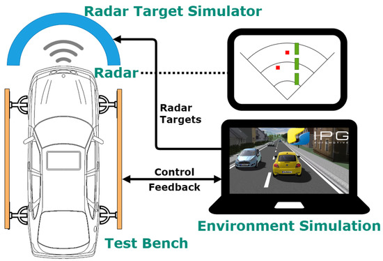
Figure 1.
Overall system design.
3. Vehicle-in-the-Loop Test Bench
In order to meet the challenges of developing and testing ADAS in an efficient way, novel testing paradigms have been proposed in recent years that have trended toward approaches employing fully integrated Vehicle-in-the-Loop test benches. These test benches can be subdivided into roller dynamometer and power train test benches. Both setups have their strengths and weaknesses with regard to testing radar-based driver assistance systems.
3.1. Literature Review
The design of roller dynamometers is familiar to most people and is the most commonly used test bench type. Figure 2 shows an example setup. This setup characterized by its flexibility in research and development. For example, exhaust gas measurements for certification and acoustic tests can be carried out during drive-by tests [9]. The basic design makes it easy to mount the test vehicles, as they can be driven on the dynamometer at ground level. They can be tethered without any further configuration effort. The tires roll on the roller, which simulates the road load. The tire behavior depends on various operation parameters, which might influence the test result. In most roller dynamometers, each axle is driven by a single roller.
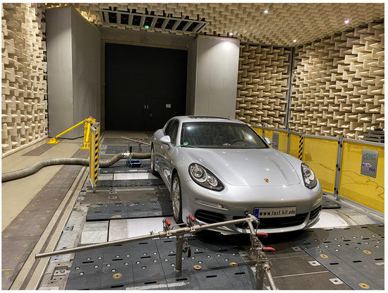
Figure 2.
VuT mounted on a chassis dynamometer.
These rollers are rigid across the width of the axle and cannot enable tire movements by steering. From this, it can be concluded that roller dynamometers can be used for the testing of radar-based, longitudinal dynamic assistance systems without any further adaptations. This can also be seen in the current approaches of ViL testing of assistance systems, as described in [7,10,11]. However, driving functions that require steerability, e.g., a Lane-Keeping-Assistant or an evasive assist, cannot be validated on a roller dynamometer without extra preparations.
To implement steerability, it is possible to bypass the steering of the VuT and substitute it with a digital steering steering wheel [12,13]. However, testing ADAS using such a digital steering solution results in the disadvantage that the vehicle and all mechatronic components cannot be tested for functionality as an integrated, holistic unit. In order to test the steering of the vehicle during the validation of driver assistance systems, the setup of the roller dynamometer has to be significantly expanded and becomes a more complex system to control. For the front axle, this involves each wheel being driven by its own roller mechanism. This mechanism consists of two rollers. Between the two rollers sits the corresponding front wheel of the vehicle, which is mounted rotatably. This allows the roller assembly to rotate with the wheels of the front axle while the vehicle is moving [6,14].
In contrast to this, power train test benches have significant advantages due to their basic design, which allows adaptation in terms of steerability. These test rigs are generally designed in such a way that each wheel hub is connected to its load engine. This allows the driving resistance to be set for each wheel individually. However, the wheels have to be removed for the power train test bench so that the wheel hubs can be connected to the load engine shafts. This demands an additional rolling resistance simulation and, thus, a very accurate tire simulation in order to obtain comparable results with the rolling test rig for the driving resistances. To enable steerabilty for this type of test bench, there are different options.
On the one hand, it is possible to set the front axle on a movable structure as described in [5]. Secondly, it is possible to unhook the vehicle steering and replace it with a steering force module [5]. With this, the steering force module will be able to implement the steering motion in a highly dynamic way. As a result, the steering capability of this uncommon test technology can also be implemented more easily than on roller chassis dynamometers.
3.2. Test Bench Setup
The authors present an existing ViL test bench that is able to handle the challenges of testing autonomous vehicles. The test bench, shown in Figure 3, is a power train test bench that comprises load machines for the simulation of driving resistances (1), aligning torque simulation units (2), an air fan for cooling of the drivetrain (3), and custom made frequency inverters (4). The test bench’s capability to test high-level algorithms for trajectory planning and track control has been reported in [15].
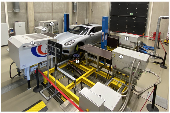
Figure 3.
Vehicle-in-the-Loop test bench.
The test bench’s special feature is the implemented aligning torque simulation units. The wheel actuators generate the corresponding aligning torque via a mechanical connection. Those torques are calculated in real time by a tire simulation for the corresponding driving situation and are applied by the actuators. This enables real driving behavior and feel during steering maneuvers. In order for the front wheels to be steerable, the mount must be movable. The front wheel supports the transmission of the vertical forces to the frame of the test rig via cross tables. This allows the wheel to move freely in its xy-plane, and the movements of the suspension are simultaneously enabled [8] so that the front wheels are steerable as described in Table 1. This test setup allows the power, energy, and consumption evaluation of modern vehicles during combined straight and curve driving. Due to its low inertia and the fast reaction of the electric load engines, an immediate and dynamic response of the driving load simulation can be achieved.

Table 1.
Technical parameters of the ViL test bench [16].
4. Environment Simulation
The traffic simulation tool utilized was developed by IPG Automotive GmbH and is called CarMaker. The simulation constructs a realistic virtual environment with respect to the vehicle dynamics, traffic behavior, and surrounding objects. The physical forces impinging on the car of interest (ego car) are extracted and passed on to the ViL test bench, which applies them to the VuT. The behavioral response is quantified and fed back into the virtual environment. Furthermore, the software tool provides the radar channel responses for the ego car’s virtual radar sensor that are needed in order to stimulate the real car’s integrated sensor.
For this task, a full electromagnetic wave propagation model is implemented. The application is based on a hardware accelerated Ray Tracing approach. Rays that represent the directed travel of electromagnetic waves are launched from the virtual sensor and interact with the objects of the simulated environment before they return back to their origin, thus, establishing a radar channel. The software application computes the propagation, reflection, and scattering of the rays in order to retrieve the radar channel impulse response from which it derives the modification parameters that are required for the radar target simulation.
The wave propagation model is enhanced by adopting a hybrid approach that includes geometrical ray tracing and physical optics. Using physical optics, a realistic picture of the environment can be built, as it would be received by a real radar sensor. Each interaction point of the traced ray is considered using the physical optics method and helps in generating a considerably higher number of detection points with a limited set of rays. This combination is very congenial considering the use case in a real-time environment.
In addition to the wave propagation, the radar sensor model in CarMaker also incorporates a device model. A careful parameterization of the device model helps in depicting the environment with similar boundary conditions laid down by the radar unit under test. The device model also indirectly helps in reducing the sheer quantity of detections generated by the ray tracer. Figure 4 depicts the 3D environment in IPG Movie and the corresponding detections (point cloud) from the radar model. The radar model is parameterized with the information available from the RTS, e.g., the field of view, number of angle segments, etc.
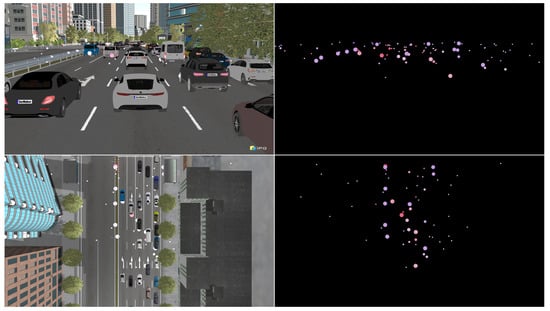
Figure 4.
IPG Movie 3D environment with radar model detections.
Since the target simulator is physically limited by the number of echoes it can generate, the detections from the sensor model are further processed. A statistical model that identifies the potential targets and maps their channel responses to the respective front end angle segments has been developed. The number of echoes the model outputs can be adjusted arbitrarily and can, thereby, be matched to the number of virtual radar targets the RTS systems is able to generate.
5. Radar Target Simulation
Radar Target Simulators have recently attracted great attention in research by virtue of their ability to thoroughly test radar sensors under laboratory conditions [17]. An RTS creates virtual radar targets that are to be perceived by the radar under test (RuT). For this, an RTS receives, modifies, and re-transmits the signal emitted by the RuT [18]. Prior to the modification, it is necessary to down convert and up convert the signal’s frequency, since the pending alterations cannot be performed at the signal’s carrier frequency of 77 GHz.
The three main characteristics that make up a radar target and, in relation to which, an RTS must adapt the radar signal are the target’s range, radial velocity, and electromagnetic magnitude, also known as the radar cross section (RCS). These attributes are emulated by adjusting the signal delay, Doppler shift, and attenuation and can be performed in either the analog or the digital domain. Therefore, RTS systems can be differentiated by their analog or digital implementation. As both approaches have their advantages and disadvantages, the criteria that distinguish them will be analyzed in the following.
5.1. Literature Review
Analog Radar Target Simulators execute the aforementioned signal modifications utilizing analog radio frequency (RF) components. The target’s range is simulated with optical or electrical delay lines, Surface Acoustic Wave (SAW) filters, or frequency mixers. Delay lines emulate the radar signal travel through free space with mono mode optical fiber [19,20] or coaxial cable [21] with a length according to the target’s range. SAW filters introduce a pre-defined group delay to the signal [22], whereas direct frequency mixing takes advantages of the linear frequency slope of automotive Frequency Modulated Continuous Wave (FMCW) radars [23,24] and is, therefore, limited to this particular modulation scheme. The target’s velocity is simulated in one of three ways. Either with a vector modulator that directly converts the signal’s instantaneous frequency by a respective Doppler shift [25,26] with digitally controlled phase shifters [27] or by applying a frequency offset to the local oscillator for the up and down conversion [19]. The target’s RCS is simulated by attenuating the signal with a variable gain amplifier (VGA).
The advantages that distinguish an analog RTS are a very low minimum simulatable target range and its potentially cost-effective implementation. Due to the absence of latency afflicted analog-to-digital converters (ADC) and digital-to-analog converters (DAC), which are needed for digital radar target simulation, analog RTS systems allow the generation of virtual radar targets in close vicinity of the RuT [18]. Moreover, the utilization of RF components enables highly integrated, low-budget designs. However, this comes at the cost of inflexibility, since the signal modifications are realized with dedicated hardware components and cannot be easily reconfigured. This results in a fixed and relative low number of possible virtual targets. Furthermore, delaying the signal with optical or coaxial delay lines only allows a rough discretization of the simulated range.
In contrast, digital Radar Target Simulators create artificial radar targets in the digital domain employing a field-programmable gate array (FPGA) after a preceding analog-to-digital conversion. The required echo signal can be generated through signal modification similar to the analog RTS through the playback of pre-recorded real radar measurements or by re-synthesis of the incoming radar signal. In analogy to the previously mentioned analog implementation, digital RTS systems simulate the range of virtual targets by applying a controllable delay. This task is performed through buffering the samples in memory [28,29] or with a digital finite impulse response (FIR) filter [30].
The target’s radial velocity is simulated through shifting the radar signal by a respective Doppler offset with either a complex quadrature mixer [28,29] or through fine range discretization [31]. The attenuation of the signal implemented on a digital signal processor (DSP) enables the control of the target’s RCS. Alternatively, the recorded samples of a complete traffic scenario measure with a radar sensor can be played back to the RuT in order to stimulate it with artificial targets [17,32]. Furthermore, it has also been shown that the analysis and re-synthesis of the transmitted radar signal can generate a realistic virtual environment for a RuT [33].
As mentioned before, digital RTS systems are limited in their ability to create near field targets, since the utilized ADCs and DACs introduce an inherent latency to the radar signal, which leads to a minimal simulatable range of around 20 to 30 m. In addition, the relative large initial monetary outlay resulting from the cost of fast sampling signal converters and the FPGA is another drawback of digital RTS. However, considering the significant larger number of targets digital systems can represent, the financial input for a realistic traffic scenario with a multitude of radar targets is well below that of an analog RTS system. Furthermore, the digital version provides great flexibility regarding how radar targets can be generated, including data-driven approaches.
These rely on radar recordings that are processed in order to play back the scenario to the RUT and, therefore, enable extremely realistic and sophisticated validation testing [34,35]. Other advantages include the capability of post implementation configuration of FPGAs and the arbitrarily fine discretization of targets in the range, and Doppler and RCS domain. Considering the goal of the system design of this paper to implement a test setup for ADAS functions, the disadvantage of not being able to simulate targets in the close range of the sensor is negligible, as initially mainly highway scenarios are relevant for the current state of the development of autonomous driving.
In addition to the aforementioned research systems, Radar Target Simulators from commercial test equipment manufacturers have been brought to market [36,37,38,39]. However, these are only suitable for use in a Vehicle-in-the-Loop test setup to a limited extent. Since they are designed for end-of-line testing, they can only represent a single digit number of targets and come at unit prices in the magnitude of hundreds of thousands of dollars. This makes them unsuitable for the integration on a large scale in such a test setup.
As RTS systems have already been successfully integrated into vehicle test beds, they lack the capability of simulating a sufficient amount of targets to realistically represent complex traffic scenarios [18] or are limited to conventional FMCW or chirp sequence modulated radars [33]. Future automotive radar sensors, however, will have the ability to create high resolution, three-dimensional radar images [40,41]. These sensors will necessitate the simulation of virtual scenarios that comprise a high number of artificial radar echoes. In addition to the conventional FMCW and chirp sequence modulation already established today, upcoming automotive radars might be based on other modulation schemes, such as orthogonal frequency division multiplexing (OFDM) or phase modulated continuous wave (PMCW) [42,43,44,45]. One of these integrated RTS systems realizes the lateral movement of targets by mechanically displacing the RTS antennas allowing the simulation of only a limited amount of targets with a rather slow cross movement speed [46].
5.2. Modular Multi Angle Radar Target Simulator
To overcome the limitations of the Radar Target Simulators mentioned above, the authors implemented a modular, cost-efficient, digital RTS system conceptualised with particular attention to its integration into a Vehicle-in-the-Loop test bed. This allows the simulation of a multitude of virtual radar targets and works for all popular modulation schemes. The design employs an UltraScale+ RFSoC FPGA [47] manufactured by Xilinx in San Jose, CA, USA as the digital back end. This enables the generation of a great amount of virtual radar targets all on a single component. Moreover, the RFSoC packs eight integrated ADCs and DACs each, which facilitate the implementation of multiple radar target simulation channels on a single FPGA. This helps to reduce the price of the setup considerably. Furthermore, due to the modularization of the simulation channels as well as the back and front ends, the system can be easily expanded and is well suited for the current development of high resolution imaging radar.
As depicted in Figure 5, the RuT transmits (Tx) a radar signal that is received (Rx) and down converted by the RTS using a frequency mixer and an additional signal created by a local oscillator at a frequency of fLO. Following, the signal is digitilized by an ADC. For the generation of virtual radar targets, the received radar signal is modified in respect of its delay, frequency, and amplitude. These modifications are performed in the digital domain, and a target’s radial velocity v is simulated by discretely shifting the signal’s frequency by a Doppler offset of
where denotes the radar signal carrier frequency, and denotes the speed of light. The range of the virtual target R is simulated by buffering and, thereby, delaying the radar signal by
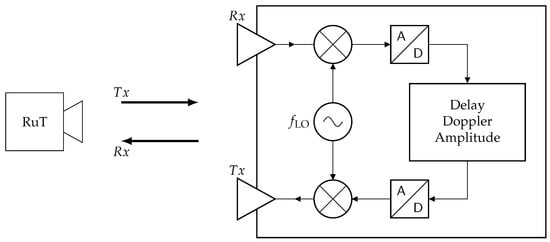
Figure 5.
The digital radar target simulator concept.
The target’s RCS is simulated by multiplying the quantized signal with an attenuation of
Subsequently, the modified radar signal is converted back to the analog domain by a DAC and up converted to its original carrier frequency utilizing a further frequency mixer and the same local oscillator signal, before it is transmitted (Tx) back towards the RuT (Rx).
The angle under which a real target’s echo signal would arrive at the radar sensor (angle of arrival) is simulated by distributing several RTS front ends in a semicircle formation around the RuT, as can be observed in Figure 1. As radar sensors are limited in their ability to resolve targets in the angular domain subdividing their field of view into defined angle segments, the placement of the front ends is dependent on this. Thus, the design at hand places one front end per segment and electronically switches between them for lateral moving targets.
6. Measurement
To demonstrate the functional operation of the RTS in combination with the ViL test bench, a measurement campaign has been conducted. For this, a test vehicle provided by Daimler AG in Stuttgart, Germany with an integrated automotive radar sensor ARS510 from ADC Automotive Distance Control Systems GmbH in Lindau (Bodensee), Germany was mounted onto the test bench. The RTS system was set up in front of the VuT as depicted in Figure 6. The RTS front end array was arranged in a semicircle formation and behind a curved metal sheet with round cutouts for the front end antennas.
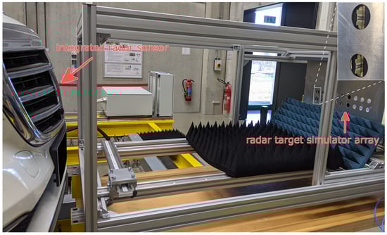
Figure 6.
The measurement setup.
The usage of the curved metal sheet served two purposes. First, it facilitated the positioning of the individual front end modules in an equidistant range from the radar sensor, and secondly it shielded off the surrounding objects behind the RTS setup. This helped to encage interfering static radar reflections originating from the metal structures of the ViL test bench and the laboratory wall and enabled the application of a range gate filter that only let the virtual radar targets pass.
For the virtual vehicle environment simulation, a static traffic scenario was chosen with three lateral displaced cars at radial distances of 82, 86, and 88 m. Additionally, a wall that limited the simulated radar channels’ travel distance was implemented at a range of 95 m. The corresponding signal delays and attenuations were calculated according to (2) and (3), respectively, and applied to the radar signal by the RTS back end. For simplicity, the relative velocities were set to zero, and no Doppler shift (1) was applied. Visual renderings of the top, side, and front view, of the scenario, including the radar model detections in CarMaker, are depicted in Figure 7.
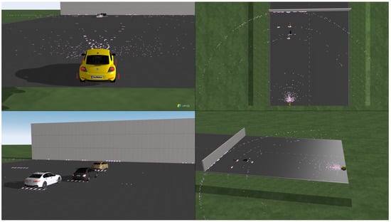
Figure 7.
Measurement scenario with radar model detections.
The yellow car represents the VuT, the white, black, and beige car, are the potential radar targets, and the pink dots illustrate the radar model detections from the CarMaker’s integrated electromagnetic wave propagation model. A vast amount of the detections were calculated. In addition to the detection points on the three object cars and the concluding wall, seemingly irregular detections in circular formations can be observed. These result from multi reflection paths that arise from the simulation’s statistical model that considers realistic environment conditions, such as road clutter and RCS fluctuations.
At the time the measurement was performed, only two RTS front ends had been assembled. However, as can be seen in the visual output of the measurement equipment shown in Figure 8, the commercial radar sensor not only detects the simulated targets at the corresponding ranges but is also able to resolve them in the angular domain. The red rectangles indicate the radar’s detected and tracked targets that result from its internal signal processing. This proves that the RTS is capable of simulating multiple targets per channel and can also represent traffic scenarios with lateral distributed objects. Together with the capabilities of the ViL test bench, as they have already been described in Section 3, this setup represents a closed loop test environment that is suited for the development and evaluation of AD functions.
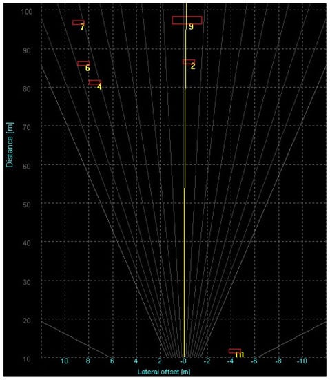
Figure 8.
Output of the Continental ARS510 radar sensor.
7. Conclusions
We presented the system design and implementation of a fully integrated Vehicle-in-the-Loop test system incorporating a vehicle dynamics test bench and a digital Radar Target Simulator. The test bench, on which the Vehicle under Test was mounted, was controlled by CarMaker’s realistic virtual vehicle environment. The vehicle’s radar sensor was stimulated with a multi-channel, multi-echo Radar Target Simulator. The vehicle’s behavioral response was looped back into the simulations forming a closed-loop, fully integrated test setup.
For future measurements, adaptive driving control will be realized in order to demonstrate the suitability of the framework for autonomous driving function development and validation.
Author Contributions
Conceptualization, T.Z. and M.P.; methodology, T.Z. and A.D.; software, A.D. and P.V.K.; validation, C.K., B.G., T.K., P.V.K. and A.D.; formal analysis, A.D., P.V.K. and C.K.; investigation, A.D., P.V.K. and C.K.; resources, B.G., M.G. and P.V.K.; data curation, A.D. and P.V.K.; writing—original draft preparation, A.D., P.V.K. and C.K.; writing—review and editing, A.D.; visualization, A.D., P.V.K. and C.K.; supervision, M.P., T.Z. and F.G. All authors have read and agreed to the published version of the manuscript.
Funding
This research was funded by the German Federal Ministry for Economic Affairs and Energy in the project Prüfstandtaugliches Hardware-in-the-Loop (HiL) Testverfahren für radarbasierte Fahrerassistenzsysteme.
Institutional Review Board Statement
Not applicable.
Informed Consent Statement
Not applicable.
Data Availability Statement
Not applicable.
Acknowledgments
The authors would like to thank Daimler AG and ADC Automotive Distance Control Systems GmbH for making this measurement campaign possible by providing a suitable test vehicle and the necessary measurement equipment. The authors acknowledge the support by the KIT-Publication Fund of the Karlsruhe Institute of Technology.
Conflicts of Interest
The authors declare no conflict of interest.
References
- Patole, S.M.; Torlak, M.; Wang, D.; Ali, M. Automotive radars: A review of signal processing techniques. IEEE Signal Process. Mag. 2017, 34, 22–35. [Google Scholar] [CrossRef]
- Maurer, M.; Gerdes, J.; Lenz, B.; Winner, H. Autonomes Fahren—Technische, Rechtliche und Gesellschaftliche Aspekte; Springer: Wiesbaden, Germany, 2015. [Google Scholar] [CrossRef]
- Schneider, S. How to Measure/Calculate Radar System MTBF? In Proceedings of the European Microwave Conference 2017, Nuremberg, Germany, 8–13 October 2017. [Google Scholar]
- Koopman, P.; Wagner, M. Challenges in Autonomous Vehicle Testing and Validation. SAE Int. J. Transp. Saf. 2016, 4, 15–24. [Google Scholar] [CrossRef]
- Schyr, C.; Brissard, A. DrivingCube—A novel concept for validation of powertrain and steering systems with automated driving. In Advanced Vehicle Control; CRC Press: Boca Raton, FL, USA, 2016; pp. 79–84. [Google Scholar] [CrossRef]
- Solmaz, S.; Holzinger, F. A Novel Testbench for Development, Calibration and Functional Testing of ADAS/AD Functions. In Proceedings of the 2019 IEEE International Conference on Connected Vehicles and Expo (ICCVE), Graz, Austria, 4–8 November 2019; pp. 1–8. [Google Scholar] [CrossRef]
- Gowdu, S.B.J.; Asghar, M.E.; Stephan, R.; Hein, M.A.; Nagel, J.; Baumgärtner, F. System architecture for installed-performance testing of automotive radars over-the-air. In Proceedings of the 2018 IEEE MTT-S International Conference on Microwaves for Intelligent Mobility (ICMIM), Munich, Germany, 16–17 April 2018; pp. 1–4. [Google Scholar] [CrossRef]
- Gießler, M.; Rautenberg, P.; Gauterin, F. Consumption-relevant load simulation during cornering at the vehicle test bench VEL. In 20. Internationales Stuttgarter Symposium 7; Springer Fachmedien Wiesbaden: Wiesbaden, Germany, 2020; pp. 159–172. [Google Scholar] [CrossRef]
- Paulweber, M.; Lebert, K. Mess- und Prüfstandstechnik; Springer: Wiesbaden, Germany, 2014. [Google Scholar] [CrossRef]
- Gietelink, O.; Ploeg, J.; De Schutter, B.; Verhaegen, M. Development of advanced driver assistance systems with vehicle hardware-in-the-loop simulations. Veh. Syst. Dyn. 2006, 44, 569–590. [Google Scholar] [CrossRef]
- Bock, T.; Maurer, M.; Farber, G. Validation of the Vehicle in the Loop (VIL); A milestone for the simulation of driver assistance systems. In Proceedings of the IEEE Intelligent Vehicles Symposium, Istanbul, Turkey, 13–15 June 2007; pp. 612–617. [Google Scholar] [CrossRef]
- Galko, C.; Rossi, R.; Savatier, X. Vehicle-Hardware-In-The-Loop system for ADAS prototyping and validation. In Proceedings of the 2014 International Conference on Embedded, Ostrava, Czech Republic, 25–27 August 2014; pp. 329–334. [Google Scholar] [CrossRef]
- Galko, C.; Rossi, R.; Savatier, X.; Payá-Vayá, G.; Blume, H. Validating Reliability of Automated Driving Functions on a Steerable VEhicle-in-the-Loop (VEL) Test Bench. In Towards a Common Software/Hardware Methodology for Future Advanced Driver Assistance Systems; River Publishers: Gistrup, Denmark, 2017. [Google Scholar] [CrossRef]
- Wang, W.; Zhao, X.; Zhen, W.; Shi, X.; Xu, Z. Research on Steering-Following System of Intelligent Vehicle-in-the-Loop Testbed. IEEE Access 2020, 8, 31684–31692. [Google Scholar] [CrossRef]
- Han, C.; Seiffer, A.; Orf, S.; Hantschel, F.; Li, S. Validating Reliability of Automated Driving Functions on a Steerable VEhicle-in-the-Loop (VEL) Test Bench. In 21. Internationales Stuttgarter Symposium; Springer Fachmedien Wiesbaden: Wiesbaden, Germany, 2021. [Google Scholar] [CrossRef]
- Institute of Vehicle System Technology, Karlsruhe Institute of Technology. Vehicle-In-the-Loop Test Bench. 2020. Available online: https://www.fast.kit.edu/lff/4667.php (accessed on 18 May 2021).
- Dallmann, T.; Mende, J.; Wald, S. ATRIUM: A Radar Target Simulator for Complex Traffic Scenarios. In Proceedings of the 2018 IEEE MTT-S International Conference on Microwaves for Intelligent Mobility (ICMIM), Munich, Germany, 16–17 April 2018; pp. 1–4. [Google Scholar]
- Gadringer, M.E.; Maier, F.M.; Schreiber, H.; Makkapati, V.P.; Gruber, A.; Vorderderfler, M.; Amschl, D.; Metzner, S.; Pflügl, H.; Bösch, W.; et al. Radar target stimulation for automotive applications. IET Radar Sonar Navig. 2018, 12, 1096–1103. [Google Scholar] [CrossRef]
- Engelhardt, M.; Pfeiffer, F.; Biebl, E. A high bandwidth radar target simulator for automotive radar sensors. In Proceedings of the 2016 European Radar Conference (EuRAD), London, UK, 5–7 October 2016; pp. 245–248. [Google Scholar]
- Lutz, S.; Erhart, C.; Walte, T.; Weigel, R. Target simulator concept for chirp modulated 77 GHz automotive radar sensors. In Proceedings of the 2014 11th European Radar Conference, Rome, Italy, 8–10 October 2014; pp. 65–68. [Google Scholar] [CrossRef]
- Gruber, A.; Gadringer, M.; Schreiber, H.; Amschl, D.; Bösch, W.; Metzner, S.; Pflügl, H. Highly scalable radar target simulator for autonomous driving test beds. In Proceedings of the 2017 European Radar Conference (EURAD), Nuremberg, Germany, 11–13 October 2017; pp. 147–150. [Google Scholar] [CrossRef]
- Arzur, F.; Le Roy, M.; Pérennec, A.; Tanné, G.; Bordais, N. Hybrid architecture of a compact, low-cost and gain compensated delay line switchable from 1 m to 250 m for automotive radar target simulator. In Proceedings of the 2017 European Radar Conference (EURAD), Nuremberg, Germany, 11–13 October 2017; pp. 239–242. [Google Scholar] [CrossRef]
- Rafieinia, F.; Haghighi, K. ASGARDI: A Novel Frequency-based Automotive Radar Target Simulator. In Proceedings of the 2020 IEEE MTT-S International Conference on Microwaves for Intelligent Mobility (ICMIM), Heidelberg, Germany, 27–29 April 2020; pp. 1–4. [Google Scholar] [CrossRef]
- Iberle, J.; Rippl, P.; Walter, T. A Near-Range Radar Target Simulator for Automotive Radar Generating Targets of Vulnerable Road Users. IEEE Microw. Wirel. Components Lett. 2020, 30, 1213–1216. [Google Scholar] [CrossRef]
- Gadringer, M.; Schreiber, H.; Gruber, A.; Vorderderfler, M.; Amschl, D.; Bösch, W.; Metzner, S.; Pflügl, H.; Paulweber, M. Virtual reality for automotive radars. e i Elektrotechnik und Informationstechnik 2018, 135. [Google Scholar] [CrossRef]
- Iberle, J.; Mutschler, M.A.; Scharf, P.A.; Walter, T. A Radar Target Simulator for Generating Micro-Doppler-Signatures of Vulnerable Road Users. In Proceedings of the 2019 16th European Radar Conference (EuRAD), Paris, France, 2–4 October 2019; pp. 17–20. [Google Scholar]
- Ourednik, P.; Zidkov, A.; Hudec, P. Doppler Frequency-Shift Unit for Digital-Analog Automobile Radar Target Simulator. In Proceedings of the 2019 European Microwave Conference in Central Europe (EuMCE), Prague, Czech Republic, 13–15 May 2019; pp. 281–284. [Google Scholar]
- Sobotka, J.; Novak, J. Digital Vehicle Radar Sensor Target Simulation. In Proceedings of the 2020 IEEE International Instrumentation and Measurement Technology Conference (I2MTC), Dubrovnik, Croatia, 25–28 May 2020; pp. 1–5. [Google Scholar] [CrossRef]
- Zhang, J.; Zhang, L.; Gao, P.; Shen, F. An FPGA based real-time radar target simulator with high spur suppression. In Proceedings of the 2020 15th IEEE International Conference on Signal Processing (ICSP), Beijing, China, 6–9 December 2020; Volume 1, pp. 126–130. [Google Scholar] [CrossRef]
- Steins, M.; Diewald, A.R. Implementation of delay line with fine range discretization for radar target simulations. In Proceedings of the 2018 19th International Radar Symposium (IRS), Bonn, Germany, 20–22 June 2018; pp. 1–9. [Google Scholar] [CrossRef]
- Steins, M.; Müller, S.; Diewald, A.R. Digital Doppler Effect Generation with CORDIC Algorithm for Radar Target Simulations. In Proceedings of the 2019 23rd International Conference on Applied Electromagnetics and Communications (ICECOM), Dubrovnik, Croatia, 30 September–2 October 2019; pp. 1–5. [Google Scholar] [CrossRef]
- Peng, Z. Realization of DRFM radar target simulator based on general instruments. In Proceedings of the IET International Radar Conference 2015, Hangzhou, China, 14–16 October 2015; pp. 1–8. [Google Scholar] [CrossRef]
- Wald, S.; Mathy, T.; Nair, S.; Leon, C.M.; Dallmann, T. ATRIUM: Test Environment for Automotive Radars. In Proceedings of the 2020 IEEE MTT-S International Conference on Microwaves for Intelligent Mobility (ICMIM), Heidelberg, Germany, 27–29 April 2020; pp. 1–4. [Google Scholar] [CrossRef]
- Leon, C.M.; González-Huici, M.A.; Dallmann, T. Data-driven Generation of Road Scenarios for Radar Target Simulation in Automotive Context. In Proceedings of the 2019 IEEE MTT-S International Conference on Microwaves for Intelligent Mobility (ICMIM), Detroit, MI, USA, 15–17 April 2019; pp. 1–5. [Google Scholar] [CrossRef]
- Iberle, J.; Rippl, P.; Walter, T. A Radar Target Simulator for Generating Synthesised and Measured micro-Doppler-Signatures of Vulnerable Road Users. In Proceedings of the 2020 17th European Radar Conference (EuRAD), Utrecht, The Netherlands, 10–15 January 2021; pp. 218–221. [Google Scholar] [CrossRef]
- Rohde & Schwarz. Better than Real Life: Radar Echoes from a Target Simulator. 2021. Available online: https://cdn.rohde-schwarz.com/pws/dl_downloads/dl_common_library/dl_news_from_rs/213/NEWS_213_ARTS9510_english.pdf (accessed on 18 May 2021).
- Keysight. E8707A Radar Target Simulator 76 GHz to 77 GHz. 2017. Available online: https://www.keysight.com/us/en/assets/7018-05310/brochures/5992-1648.pdf (accessed on 18 May 2021).
- dSpace. DARTS 9040-G, The First True 5 GHz Bandwidth Radar Target Simulator. 2020. Available online: https://www.dspace.com/shared/data/pdf/2020/DARTS_9040-G_Product_information_201002_E.pdf (accessed on 18 May 2021).
- Eyerly, D. TS10105—Testing Automotive Radar Sensors with the NI Active Target Simulator and a LabVIEW-Based Scene Editor. Natl. Instrum. Week 2016, 2016, 3–4. [Google Scholar]
- Wenger, J. Future Trends in Automotive Radar/Imaging Radar. In Proceedings of the 1998 28th European Microwave Conference, Amsterdam, The Netherlands, 5–9 October 1998; Volume 1, pp. 636–641. [Google Scholar] [CrossRef]
- Giannini, V.; Goldenberg, M.; Eshraghi, A.; Maligeorgos, J.; Lim, L.; Lobo, R.; Welland, D.; Chow, C.; Dornbusch, A.; Dupuis, T.; et al. 9.2 A 192-Virtual-Receiver 77/79 GHz GMSK Code-Domain MIMO Radar System-on-Chip. In Proceedings of the 2019 IEEE International Solid- State Circuits Conference (ISSCC), San Francisco, CA, USA, 17–21 February 2019; pp. 164–166. [Google Scholar] [CrossRef]
- Nuss, B.; Diewald, A.; Schoepfel, J.; Martini, D.; Pohl, N.; Zwick, T. 76 GHz OFDM Radar Demonstrator with Real-Time Processing for Automotive Applications. In Proceedings of the 2020 IEEE MTT-S International Conference on Microwaves for Intelligent Mobility (ICMIM), Heidelberg, Germany, 27–29 April 2020; pp. 1–4. [Google Scholar] [CrossRef]
- Haderer, H.; Feger, R.; Pfeffer, C.; Stelzer, A. Millimeter-Wave Phase-Coded CW MIMO Radar Using Zero- and Low-Correlation-Zone Sequence Sets. IEEE Trans. Microw. Theory Tech. 2016, 64, 4312–4323. [Google Scholar] [CrossRef]
- Bourdoux, A.; Ahmad, U.; Guermandi, D.; Brebels, S.; Dewilde, A.; Van Thillo, W. PMCW waveform and MIMO technique for a 79 GHz CMOS automotive radar. In Proceedings of the 2016 IEEE Radar Conference (RadarConf), Philadelphia, PA, USA, 1–6 May 2016; pp. 1–5. [Google Scholar] [CrossRef]
- Wiesbeck, W.; Sit, L. Radar 2020: The future of radar systems. In Proceedings of the 2014 International Radar Conference, Lille, France, 13–17 October 2014; pp. 1–6. [Google Scholar] [CrossRef]
- Buddappagari, S.; Asghar, M.E.; Baumgärtner, F.; Graf, S.; Kreutz, F.; Löffler, A.; Nagel, J.; Reichmann, T.; Stephan, R.; Hein, M.A. Over-the-Air Vehicle-in-the-Loop Test System for Installed-Performance Evaluation of Automotive Radar Systems in a Virtual Environment. In Proceedings of the 2020 17th European Radar Conference (EuRAD), St. Petersburg, Russia, 14–18 June 2021; pp. 278–281. [Google Scholar] [CrossRef]
- Xilinx. Zynq UltraScale+ RFSoC. 2018. Available online: https://www.xilinx.com/products/silicon-devices/soc/rfsoc.html (accessed on 18 May 2021).


Publisher’s Note: MDPI stays neutral with regard to jurisdictional claims in published maps and institutional affiliations. |
© 2021 by the authors. Licensee MDPI, Basel, Switzerland. This article is an open access article distributed under the terms and conditions of the Creative Commons Attribution (CC BY) license (https://creativecommons.org/licenses/by/4.0/).