Abstract
A molten-metal catalyst exhibits strong resistance to carbon encapsulation and deactivation, due to its unique physical and chemical properties, demonstrating excellent catalytic activity and stability. This paper overviews recent developments in molten-metal catalysts for methane cracking and hydrogen production. It thoroughly examines the stability of reactors, carbon products, and catalysts for each molten-metal system. The kinetics and mechanism of the catalysts in each system have also been analyzed. Finally, for future development, several recommendations for hydrogen production via methane cracking have been proposed, addressing the following research challenges: (1) gaining a deeper understanding of the active sites and methane conversion process, which can provide crucial guidance for designing high-performance catalysts; (2) fostering the advancement of new reaction interfaces; and (3) attempting to develop a low-eutectic-point molten salt system for chemical vapor deposition reactions. The molten-metal catalyst exhibits strong resistance to carbon encapsulation and deactivation due to its unique physical and chemical properties, demonstrating excellent catalytic activity and stability.
1. Introduction
Due to the emission of greenhouse gases caused by human activities, the global average temperature increased by 1.1 °C from 2011 to 2020 [1,2,3]. As a zero-emission energy vector, molecular hydrogen (H2) has emerged as a pivotal enabler for global decarbonization mandates under the Paris Agreement framework, offering viable displacement pathways for carbon-intensive fossil derivatives across the industrial and mobility sectors [4,5]. In the POX process, methane/hydrocarbons are partially oxidized to form the syngas under the sub-stoichiometric oxygen conditions [6]. Diverging from conventional gaseous hydrocarbon feedstocks, coal gasification employs solid-phase carbonaceous matrices (anthracite/bituminous coal) as precursors, undergoing staged thermochemical conversion through gas–solid interactions with multiple oxidizing agents—principally, steam (H2O), oxygen-enriched atmospheres (O2 > 95%), or carbon dioxide (CO2) under autothermal conditions (800–1500 °C) [7]. Cleaner H2 production technology and raw materials need to be explored and developed to achieve decarbonization in the H2 production process.
The hydrogen production landscape has evolved into a multi-paradigm ecosystem encompassing five technological pillars: (1) charge-transfer systems (electrolysis/photoelectrolysis), (2) thermal-redox cycles (sulfur-iodine/cerium oxide), (3) biocatalytic pathways (dark fermentation/photobiological), (4) photon-driven processes (Z-scheme photocatalysis), and (5) waste-valorization platforms utilizing carbonaceous refuse streams (plastic pyrolysis gas: CxHyOz → H2 + CNTs) [8,9]. This diversification strategically aligns with circular hydrogen economy principles, according to which municipal solid wastes (MSW, 1.3 billion tons/year globally) and lignocellulosic biomass (50 EJ/year potential) replace virgin fossil inputs through gasification/reforming cascades. Since Lavoisier’s 1783 water decomposition experiments, electrolytic hydrogen synthesis has matured into the dominant carbon-negative pathway (ηsystem > 80% at 4.5 kWh/Nm3), particularly when integrated with intermittent renewables—photovoltaic–electrolyzer systems achieve <$3/kg H2 at 2000 h/year PEM operation. Recent breakthroughs in anion-exchange membranes (AEM) enable current densities exceeding 2 A/cm2 at 1.8 V, positioning electrolysis as the linchpin for achieving terawatt-scale green hydrogen infrastructure [10].
Methane (primarily sourced from abundant and relatively inexpensive natural gas) is the dominant feedstock for hydrogen production today primarily due to its economic and practical advantages. The established steam methane reforming (SMR) process is highly efficient and scalable for large industrial needs, and leverages existing global natural gas infrastructure, making it the lowest-cost method currently available. While this process emits carbon dioxide, the resulting hydrogen is itself a valuable, cleaner-burning fuel or chemical feedstock, especially compared to direct fossil fuel use. Furthermore, converting methane to hydrogen facilitates the development of hydrogen infrastructure and markets, acting as a practical bridge to future cleaner hydrogen production methods (like electrolysis powered by renewables), especially when combined with carbon capture and storage (“blue hydrogen”). Catalytic methane decomposition (CMD) emerges as a carbon-neutral hydrogen production strategy, generating ultrapure hydrogen (H2) and tunable carbon nanomaterials (e.g., turbostratic graphitic platelets, carbon nanofibers) through a single-step process that eliminates CO2 by-product generation, circumventing energy-intensive carbon-capture systems [11] (Figure 1). The resultant structural carbon allotropes demonstrate multifunctional commercial viability as supercapacitor electrodes (specific surface area > 1500 m2/g), carbon nanotube-reinforced polymers (tensile strength enhancement ≥ 300%), and lithium-ion battery anodes (capacity retention > 90% after 500 cycles), while the radical-mediated reaction mechanism enables continuous catalyst regeneration via spontaneous carbon detachment, avoiding the reactor fouling common in steam reforming. Methane cracking technology can reduce greenhouse gas emissions by up to 75% compared to steam reforming. The solid carbon by-products produced can be utilized in various applications, including amorphous carbon black, structured graphite, and specialized carbon nanotubes and fibers [12]. This dual-output paradigm synergistically addresses hydrogen economy scalability and advanced material supply chain demands.
CH4(g) → C (s) + 2H2 (g), ΔH298 K = 74.9 kJ/mol
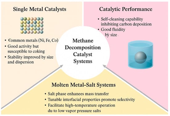
Figure 1.
Schematic showing properties and characteristics of methane decomposition.
This process can use various feedstocks, such as natural gas, biogas, syngas from biomass gasification, and other hydrocarbons, enhancing its practicality and sustainability [13].
Using a solid metal catalyst can lower the required reaction temperature [14], but one drawback is that carbon buildup can deactivate the catalyst’s active sites, hindering the reaction [15,16]. Liquid metal catalysts can avoid this issue, offering a significant advantage. While this approach avoids CO2 emissions by producing solid carbon, its energy demands remain high, as it depends on thermal decomposition rather than the heat recovery techniques often used in SMR to improve efficiency [17]. The generation of solid carbon as a by-product also reduces reactor efficiency [18]. Therefore, managing and preventing carbon accumulation is a major challenge in methane pyrolysis. While carbon capture and utilization (CCU) technologies can transform solid carbon into valuable materials, they still face obstacles related to scalability, energy efficiency, and cost-effectiveness [19].
A molten catalyst is a substance that accelerates a chemical reaction while existing in a liquid state that is achieved by heating it above its melting point. Unlike solid catalysts, its liquid nature provides exceptional mixing and intimate contact between reactants and catalytic sites, significantly enhancing reaction efficiency and overcoming common limitations like mass transfer resistance. This liquid phase also inherently resists deactivation by fouling or coking, as solid deposits cannot easily block active sites. Molten catalysts, such as molten salts (e.g., carbonates, chlorides) or molten metals (e.g., tin, bismuth), are particularly valuable for demanding high-temperature processes like methane pyrolysis for clean hydrogen production, coal or biomass gasification, and certain organic syntheses, offering thermal stability and uniform heat distribution despite challenges like energy intensity and material corrosion. Molten catalysts have attracted considerable interest as a promising alternative to traditional solid catalysts due to the distinctive properties and benefits of the former [20]. Critically, molten media overcome two fundamental limitations of solid catalysts: (1) the inevitable encapsulation of solid carbon within rigid catalyst particle matrices, which permanently deactivates active sites, and (2) the unavoidable dependence on expensive noble metals (e.g., Ni, Pt). In contrast, molten salts or metals efficiently transform methane into hydrogen and solid carbon while enabling straightforward carbon-product separation [21]. This separation occurs spontaneously: solid carbon floats to the molten surface due to density differences, forming a distinct layer that is continuously removed via simple mechanical skimming or filtration techniques. This intrinsic separation capability eliminates destructive regeneration cycles, significantly boosting overall process efficiency.
Consequently, molten media lower the activation energy for methane pyrolysis, enhance reaction kinetics [22], and enable continuous operation. While carbon buildup can obstruct active sites in conventional systems, the buoyancy-driven segregation and continuous harvesting in molten systems prevent performance degradation. Molten catalysts thus facilitate methane conversion to hydrogen and separable carbon at lower temperatures or higher rates than solid analogues. Figure 1 shows key properties of methane decomposition in molten media.
2. Principle and Characteristics of Molten Catalysts
2.1. Catalytic Mechanism
Methane pyrolysis occurs through two primary mechanisms: dissociative adsorption and non-dissociative adsorption [23]. In dissociative adsorption, methane molecules split upon adsorption onto the catalyst’s active site, resulting in chemisorption and C-H bond cleavage, producing CH3 and H fragments. In non-dissociative adsorption, methane adsorbs onto the catalyst surface first, followed by a series of dehydrogenation reactions before dissociation [24].
In 1970, Grabke et al. [25] investigated the methane pyrolysis process catalyzed by α-Fe at temperatures ranging from 800 to 1400 °C. They found that methane cracked into methyl groups at a controlled rate. Their study indicated that methane pyrolysis is a multi-step dehydrogenation process, and they developed a first rate equation based on a reversible reaction rate. Five years later, Grabke et al. [25] expanded on this by studying methane cracking with Fe, utilizing Al2O3 as a catalyst. They observed that once methane adsorbed onto the catalyst, methyl groups underwent a series of dehydrogenation steps, ultimately resulting in dissolved carbon. This process was identified as non-dissociative adsorption, with the specific steps as outlined in Equations (2)–(8) [26].
CH4 + I(vacancy) → CH4 (ad)
CH4 (ad) → CH3 (ad)+ H (ad)
CH3 (ad) → CH2 (ad)+ H (ad)
CH2 (ad) → CH (ad) + H (ad)
CH (ad) → C (ad) + H (ad)
C (ad) → C (dissolve)
2H (ad)→H2 + 2I
The reaction steps involved in catalytic methane pyrolysis dissociative adsorption are similar to those involved in non-dissociative adsorption. The first step differs between the two processes. In dissociative adsorption, methane first undergoes dehydrogenation, while in non-dissociative adsorption, methane molecules are initially adsorbed onto the catalyst surface. The dissociative adsorption process is detailed in Equations (9) to (14) [26].
CH4 + I→ CH3 (ad) + H (ad)
CH3 (ad)→CH2 (ad) + H (ad)
CH2 (ad)→CH (ad) + H (ad)
CH (ad)→C (ad) + H (ad)
C (ad)→ C (dissolve)
2H (ad)→H2 + 2I
Le Chatelier’s principle suggests that increasing the reaction pressure in methane pyrolysis reduces both methane conversion and hydrogen yield at equilibrium. However, since actual operating conditions are often far from equilibrium, higher pressures may still reduce methane conversion but enhance hydrogen production. To optimize economic performance, methane cracking reactors should be operated under ideal pressure conditions to maximize both methane conversion and energy efficiency [27].
2.2. Reaction Dynamics
Although the reaction mechanism of methane catalytic decomposition is clear, the reaction kinetics often determine the methane conversion rate, and many scholars have conducted relevant research. In a molten medium, two types of reactions occur when methane bubbles rise: first, non-catalytic gas-phase cracking occurs at the center of the bubble, where methane contacts the liquid interface; second, catalytic cracking happens when the gas and liquid directly interact at the bubble’s surface. For both reactions, the forward and reverse rates need to be taken into account [28]. Methane cracking is generally considered a first-order reaction, in which the forward rate (rc,f, mol/(m2·s)) is influenced by methane concentration (Equation (15)), and the reverse rate (rc,b, mol/(m2·s)) is influenced by hydrogen concentration (Equation (16)).
where kc,f refers to the forward rate constant (m/s), while kc,b is the reverse rate constant (m4/(mol·s)). The concentration of the component is represented as c (mol/m3), and p stands for the partial pressure of the component (kPa). R represents the gas constant, valued at 8.314 J/mol·K, and T is the temperature in Kelvin (K).
The equilibrium constant (Keq, in kPa) is determined using Equation (17). When the forward and reverse rates are balanced, Equation (18) is derived. The overall reaction rate (r, mol/(m2·s)) can be calculated using Equation (19).
The methane cracking reaction, catalyzed by a liquid metal catalyst, is influenced by both reaction kinetics and hydrodynamics. Figure 2 illustrates a diagram of a liquid metal bubbling reactor, where methane is introduced from the bottom and ascends through the liquid metal in bubble form, undergoing decomposition as it rises [29].
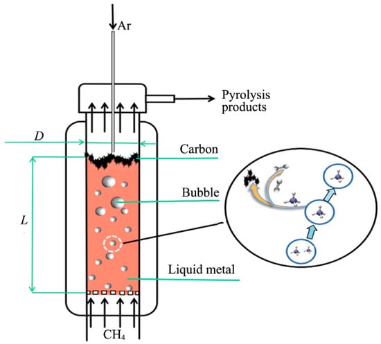
Figure 2.
Schematic diagram of liquid metal bubbling reactor. L is the height of liquid metal in the reactor, m; D is the inner diameter of the reactor, m. (Used with permission from Ref. [29]. Copyright 2024, Acta Chimica Sinica of Higher Education Institutions.)
Different aspects must be considered depending on the liquid media and bubble dimensions, especially regarding mass transport-related effects between the molten media and the gas phase [30]: (i) thermal cracking occurs homogeneously in the entire bubble volume thanks to the high heat transfer rate offered by the molten medium (Figure 3(1)); (ii) it is confined to a layer near the surface due to heat transfer limitations (calculations provided in [30] show that while these limitations are almost negligible for bubbles around 3 mm in size, they could become significant for larger bubbles, where Db > 10 mm) (Figure 3(2)); or (iii) thermal cracking takes place homogeneously in the gas bulk and heterogeneously, confined to gas/liquid interface, due to the catalytic activity offered by the molten media or by the previously deposited carbon (Figure 3(3)).
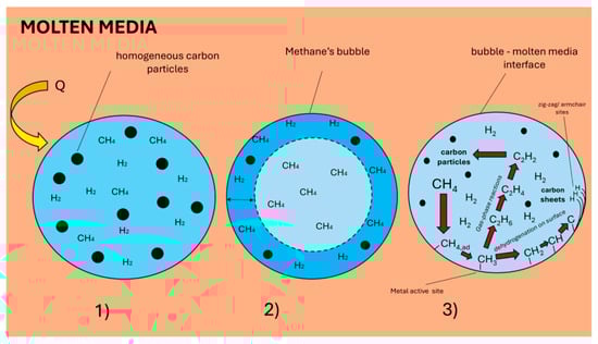
Figure 3.
The different mechanism proposed for methane pyrolysis in molten media: (1) limited by heat transfer and (2) homogeneous in the bulk of the bubble; (3) generic mechanism of molten media functionalization of methane molecule. Heterogeneous processes at the surface could be related to deposition on already structured aromatic/carbon layers and/or to specific reactivity of the molten surface. (Used with permission from Ref. [31]. Copyright 2024, Elsevier.)
The reaction temperature is crucial in influencing the kinetics of methane pyrolysis [32]. Elevated temperatures generally accelerate methane decomposition rates, facilitating a more rapid conversion to hydrogen gas and carbon solids [33]. Studies indicate that catalytic pyrolysis typically occurs between 600–900 °C, which is similar to the temperature range used in steam methane reforming (SMR) [34]. In contrast, non-catalytic methods often require much higher temperatures, exceeding 1100–1200 °C, to achieve effective methane conversion [35].
The methane conversion data from the numerous liquid metal bed (LMBR) studies is challenging to verify or incorporate into chemical kinetic models, as much of the reaction takes place above the liquid metal, and the residence time within the LMB is relatively brief [36].
where:
r = kn[CH4]
r: Rate of the reaction;
k: Rate constant;
[CH4]: Concentration of methane;
n: Order of the reaction with respect to methane.
The reaction rate in terms of Keq is expressed in the following:
Methane concentration plays a key role in determining the efficiency and results of pyrolysis, especially in molten-metal-based bubble column reactors. Changes in methane concentration directly impact the kinetic mechanisms of the process, as higher gas-phase concentrations affect molecular collision rates and intermediate species formation pathways [32].
Chemical kinetics principles dictate that the kinetic rate of methane pyrolysis is governed by reactant concentrations. Increased methane ([CH4]) availability under positive reaction order conditions (n > 0) enhances process velocity, thereby optimizing hydrogen yield and carbon solidification efficiency [37]. This acceleration arises from amplified molecular collision frequency, statistically elevating reactive encounters per temporal unit [38]. While temperature and pressure critically modulate the Arrhenius rate constant (k), thermal augmentation can offset kinetic limitations imposed by reduced methane partial pressures. Nevertheless, precise methane-to-carrier gas ratios must be maintained to mitigate operational challenges such as reactor fouling from uncontrolled carbon accumulation [39].
Bubble dimensions critically modulate reaction kinetics and product distribution patterns through interfacial dynamics. Bubble size exerts a profound regulatory effect on multiphase dynamics by governing interfacial interactions, hydrodynamic behavior, and mass/energy transfer rates. Smaller bubbles (e.g., <1 mm) exhibit high surface-area-to-volume ratios, maximizing the gas–liquid contact area for enhanced mass transfer (e.g., O2 dissolution), while their low rise velocity extends the residence time for reactions. Conversely, larger bubbles (e.g., >2 mm) develop internal circulation that reduces gas-phase resistance but suffer from diminished surface area and rapid ascent, shortening contact time. Critically, size dictates shape stability: spherical bubbles (<1 mm) follow laminar flow with diffusion-limited transfer, whereas larger bubbles deform into ellipsoidal/cap shapes, inducing turbulent wakes and oscillations that disrupt boundary layers, amplifying transfer coefficients by up to 200%. Thus, bubble size directly modulates kinetic efficiency—fine-tuning this allows engineers to prioritize interfacial reactions (via small bubbles) or bulk mixing (via large bubbles), optimizing processes like bioreactor aeration or carbon capture. Strategic minimization of bubble diameter enhances interfacial contact via amplified surface-to-volume (SA:V) ratios, thereby optimizing interphase mass transfer coefficients [34]. This geometric scaling principle dictates that SA:V increases exponentially with bubble size reduction, directly elevating the diffusive flux magnitudes that drive kinetic acceleration. Fluid-phase properties exert deterministic control over bubble size distributions: elevated liquid densities coupled with depressed surface tensions promote bubble fragmentation, yielding narrower diameter dispersions [40]. Pressure-dependent buoyancy effects further regulate bubble hydrodynamics—increasing system pressure reduces terminal rise velocities while enhancing particle entrainment capacity [41]. These multiphase transport phenomena collectively determine bubble residence time distributions, establishing critical linkages between reactor hydrodynamics and global reaction rates [42].
Significant research efforts have focused on deconvoluting methane pyrolysis mechanisms and establishing reaction mechanism frameworks across diverse catalytic systems and reactor configurations. These computational modeling approaches offer critical mechanistic insights into energy barriers (via activation energy quantification), elementary reaction steps, and rate-determining phenomena governing CH4 dissociation pathways. Advanced kinetic simulations enable predictive analysis of process dynamics under varying thermal and pressure regimes. Through synergistic integration of empirical datasets with first-principles calculations, such models delineate multivariate correlations between reaction velocities and operational parameters (e.g., T, P[CH4]). A systematic analysis of Arrhenius pre-exponential factors and temperature-dependent rate constants facilitates the development of optimization strategies aimed at maximizing hydrogen production. This paradigm facilitates rational engineering of three key domains: reactor hydrodynamics tailoring, catalytic active site modulation, and energy-intensity minimization. This collective engineering facilitates the advance toward economically sustainable methane decarbonization technologies.
Most researchers use a basic first-order kinetic model, which overlooks factors like chemical equilibrium, reverse reactions, and unwanted carbon buildup. Some studies have used alternative equations, departing from the first-order model, by adjusting the experimental data to identify the reaction order. This approach has proven effective in characterizing various methane pyrolysis processes, irrespective of reactor type or catalyst design. The rate constant’s temperature dependence is typically expressed using the Arrhenius equation. Recently, efforts have focused on refining or expanding these basic models to address issues such as non-ideal behavior, equilibrium limitations, reverse reactions, and reduced catalyst efficiency.
3. Catalyst Type
Given the widespread use of Ni- and Cu-based catalysts in methane pyrolysis for hydrogen production, the molten metals employed in this process are typically classified into three categories: Ni-based, Cu-based, and other catalysts.
3.1. Molten Metal
3.1.1. Ni-Based
While single-component molten metals exhibit catalytically uniform surface sites with limited molecular specificity, binary molten alloys leverage interfacial synergy through precisely engineered d-electron configurations of transition metal dopants (e.g., Ni) atomically dispersed in low-melting-point matrices (Sn/Bi). This atomic-scale dissolution circumvents high-temperature limitations while enabling quantum-level charge modulation at gas–liquid interfaces, where cooperative metal coordination lowers C-H bond dissociation barriers and sustains dehydrogenation cascades [30]. The dynamic equilibrium between matrix–dopant solubility—governed by electronegativity matching and operational thermodynamics (T, P)—dictates configurational entropy to achieve homogeneous single-atom dispersion, mirroring heterogeneous single-atom catalysis principles in which maximum activity emerges at quantum confinement scales [43,44].
The earliest documented application of molten alloy catalysis for methane decarbonization traces back to a 1956 patent disclosing an Al–Ni binary system where nickel concentration gradients modulated thermocatalytic performance [45]. Within this configuration, pyrolytic carbon nucleates as low-density graphitic phases that spontaneously migrate to the melt surface through buoyancy-driven separation mechanisms—a critical advantage enabling continuous operation. While elemental aluminum exhibits chemical inertness toward CH4 cleavage, its dual functionality emerges as both a high-thermal-capacity fluid medium (λ > 200 W/m·K) and structural matrix for nickel dispersion. The introduced transition metal dopants (Ni) activate interfacial catalytic cycles through d-orbital electron donation, lowering methane dehydrogenation activation barriers by ~35% compared to monometallic systems. This pioneering work established the foundational paradigm of metal “catalytic solvation”, in which molten matrices simultaneously serve as heat transfer vectors, carbon rejection platforms, and transition metal stabilizers—a tripartite synergy later quantified through modern Sabatier analysis of metal–carbon interfacial energetics. In 2017, McFarland’s team conducted a thorough study on the catalytic behavior of alloys composed of low-melting-point metals combined with nickel or platinum. They achieved a 95% methane conversion at 1065 °C using a molten alloy made of 27% nickel and 73% bismuth as the catalyst, which produced hydrogen and solid carbon (see Figure 4a) [46]. The study found that low-melting-point metals alone have limited catalytic activity in Clean Development Mechanism (CDM) reactions, but their performance improves significantly when alloyed with nickel or platinum (see Figure 4b). The researchers utilized density functional theory to analyze the physical properties of atoms and atomic clusters in the melt, finding a correlation with catalytic activity (see Figure 4c). The calculated charge of the active atom introduced into the melt was linked to its catalytic activity: a less negative charge corresponded to higher activity. The charge observed in the system is influenced by nearby inert metal atoms, emphasizing their role within the alloy. The Ni0.27Bi0.73 alloy exhibited an activation energy of 208 kJ/mol, lower than liquid bismuth but higher than carbon or solid nickel catalysts (see Figure 4d). This suggests that the alloy is more than just a physical blend of nickel and bismuth. With the active metal in the melt holding a partial negative charge, the melt can be considered a unique “monatomic” catalyst.
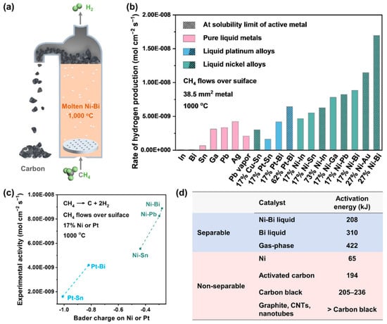
Figure 4.
Hydrogen production with molten Ni–Bi metal catalysts. (a) A molten-metal bubble column reactor for CH4 conversion to H2 and separable carbon. (b) Graphical comparison of activity for methane pyrolysis at 1000 °C, over different molten metals. (c) Activity versus calculated Bader charge on the active element. (d) Apparent activation energies for metals. (Used with permission from Ref. [46]. Copyright 2017, Science.)
In 2020, Zeng, J. et al. [47] examined the effect of adding nickel to molten tellurium, finding a surprisingly lower level of catalytic activity. The authors attributed this behavior to several factors, including a decrease in surface concentrations (particularly Te) that affects the accessibility of methane molecules in the gas phase. They also observed significant electronic interactions between Te and Ni, which resulted in a “cage” effect and a reduction in the gas-phase Te concentration in the methane bubbles. Both molten magnesium and molten tellurium have potential as monometallic molten catalysts for methane pyrolysis, although their high vapor pressures lead to considerable catalyst loss, which presents a significant practical issue.
Methane pyrolysis was conducted using 5% Ni–95% Sn and 30% Ni–70% Sn alloys at temperatures of 950 °C, 1000 °C, and 1050 °C. The results showed that the 5% Ni alloy achieved a 19% methane conversion in a 10 cm molten-metal column at 1050 °C. Kinetic analysis revealed that the pre-exponential factor (k0) for the 5% Ni alloy was much higher than for pure tin, indicating an increased reaction rate. However, the apparent activation energy (Eₐ) was also elevated, possibly due to the influence of Ni on the reaction mechanism or bubble formation. The carbon samples were analyzed using scanning electron microscopy (SEM) and Raman spectroscopy, revealing enhanced crystallinity and reduced amorphous content following the addition of Ni. The Ni–Sn alloy demonstrated strong catalytic performance in methane pyrolysis, particularly in enhancing the reaction rate constant for hydrogen production. However, its high activation energy requires further study to understand the mechanism of its influence. In 2023, Seo, J.-C. et al. [48] studied a 10 wt.% Ni–Bi catalyst, achieving a methane conversion of approximately 25%. Chen et al. [49]. studied CMD using a molten NiSn alloy catalyst for hydrogen production and graphitized carbon. Their findings emphasized how ceramic nozzles improve methane conversion rates and carbon-product quality. In CMD, methane is decomposed in a molten-metal catalyst, producing hydrogen and solid carbon. The Ni in the NiSn alloy is crucial for catalytic activity, while ceramic nozzles further boost reaction efficiency. Kinetic studies revealed that the nozzles improve the reaction rate and methane conversion by regulating bubble size and expanding the contact area. Melted liquid catalysts (MLCs) can solve the deactivation problem by removing carbon products suspended on the surface of the liquid catalyst, and they have excellent durability. However, the high activation energy of MLCs (ranging from 160 to 310 kilojoules/mole) requires the activation of methane at a higher temperature (Figure 5A). Chen et al. [49] introduced Mo to weaken the cage effect formed by the strong interaction between the active metal sites and the solvent metal, increasing the possibility of interaction between Ni and CH4, and simultaneously achieving high efficiency, selectivity and durability in the methane pyrolysis at a mild temperature.
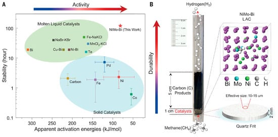
Figure 5.
Scheme of H2 production from CH4 pyrolysis. (A) Overview of catalysts for H2 production from CH4 pyrolysis, including the stability and activity of different solid and molten liquid catalysts. (B) Image of cooling down reactor after a long-duration CH4 pyrolysis reaction (Used with permission from Ref. [49]. Copyright 2023, Science.)
3.1.2. Cu-Based Alloy
In molten catalytic systems, unlike those with solid catalysts, the Bader charge and reactivity of active metal atoms fluctuate over time. In molten alloys, the CH3 radical typically attaches to the inert component, while hydrogen binds to the active metal [50].
McFarland’s team also explored the effect of adding copper, a less catalytic metal, to a bismuth melt for methane pyrolysis, yielding unexpected results [51]. The Cu–Bi molten alloy proved to be the most active molten-metal catalyst for CDM, even outperforming the Ni0.27Bi0.73 alloy. Despite pure bismuth melts having low reactivity, the interaction between bismuth and copper atoms on the alloy surface significantly improved their catalytic properties. Using ab initio molecular dynamics (MD), they calculated the activation energy for methane dissociation on the Cu–Bi alloy surface and found it to be lowest when the CH3 radical attached to the alloy. The enhanced CDM activity is likely due to the electron-deficient bismuth activated by copper (Figure 5). A similar formula was used to calculate nα(Cu, t). Figure 6 shows how the concentrations of Bi and Cu atoms vary across the liquid slab. In these simulations, we used a slab of liquid floating in vacuum, and the slab had two vacuum–liquid surfaces. If the slab was equilibrated and the statistics were satisfactory, the concentration variation within the distance across the slab should have been symmetrical with respect to the middle of the slab; the two liquid–vapor interfaces should have had the same time-averaged composition profile. This is true for the results shown in Figure 6e,f, but not those in Figure 6d. We do not have an explanation for the asymmetry in Figure 6d, and we attribute it to insufficient sampling. The density profiles show surface segregation of Bi atoms for all bulk compositions; moreover, the outermost strips contain mostly Bi [51].
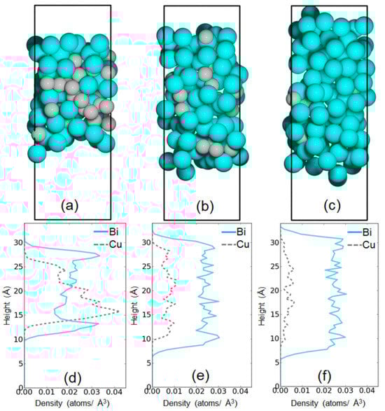
Figure 6.
Snapshots of Cu–Bi melt systems after 12 ps of MD simulations for (a) Cu45Bi55, (b) Cu20Bi80, and (c) Cu10Bi90. (d–f) Average concentration (number of atoms per cubic Angstrom) of Bi and Cu atoms as a function of the coordinate perpendicular to the slab of liquid. (Used with permission from Ref. [51]. Copyright 2019, Elsevier.)
In 2021, Zaghloul, N. et al. [22] studied various Cu–Sn alloy compositions, including 5% Cu and conducted experiments at temperatures of 950 °C, 1000 °C, and 1050 °C. They discovered that the addition of copper significantly boosted the pre-exponential factor (k0) of the reaction rate constant, which pointed to an enhancement in catalytic activity. However, as the Cu content increases, the activation energy (Ea) also increases. For example, 30% Cu alloys have a higher activation energy than pure tin. In experiments, Cu–Sn alloys generally exhibit high methane conversion rates. In particular, 30% Cu alloy shows a high conversion rate at high temperature. Figure 7 shows the methane conversion rates for different catalysts. The resulting carbon samples are analyzed by various analytical methods, such as SEM and Raman spectroscopy, and the results indicate that adding Cu enhances the crystallinity of carbon while decreasing its amorphous content. Overall, Sn–Cu alloys demonstrate strong catalytic activity in methane pyrolysis for hydrogen production, particularly in increasing the reaction rate and improving carbon-product quality. However, the higher activation energies suggest that further research is needed to optimize the reaction conditions.
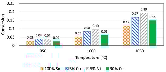
Figure 7.
Conversion in 10 cm molten-metal section. (Used with permission from Ref. [22]. Copyright 2021, Elsevier).
In 2023, David Scheiblehner et al. [52] researched the performance of different copper-based alloys as catalysts in methane pyrolysis. A CuBi alloy showed an excellent catalytic effect. As the Bi content increased, the methane conversion rate improved significantly. The CuBi80 alloy achieved the highest methane conversion rate of 68.44% after 60 min. The alloy’s low surface tension aids in forming smaller bubbles, which increases the gas–liquid interface and improves reaction efficiency. Similarly, the CuSn alloy showed promising catalytic performance, with the methane conversion rate increasing as Sn content rose. The CuSn80 alloy reached a methane conversion rate of 41.18% at 60 min. The addition of Sn further reduces surface tension, enhancing the conversion rate. The catalytic effect of the CuNi alloy is the second highest. Although the surface tension and bubble size did not change much, the catalytic effect was significantly better than that of pure copper. The methane conversion rate of CuNi5 alloy at 60 min is 55.75%, showing a high catalytic efficiency. The catalytic effect of the CuGa alloy is relatively poor. While the addition of Ga lowers the alloy’s surface tension, the lower density of liquid gallium leads to larger bubble sizes, which impacts the methane conversion rate. The CuGa5 alloy has a low methane conversion rate of only 26.50% at 60 min. In general, the CuBi alloy showed the best catalytic effect in methane pyrolysis, while the CuNi alloy also showed high catalytic efficiency. The CuSn alloy’s effect lies between those of the CuBi and CuGa alloys, with CuGa showing relatively poor performance. The results suggest that both surface tension and the bubble size of the alloy play crucial roles in methane conversion. Figure 8 depicts the results of these calculations as functions of the experimental duration for the investigated metals and alloys.
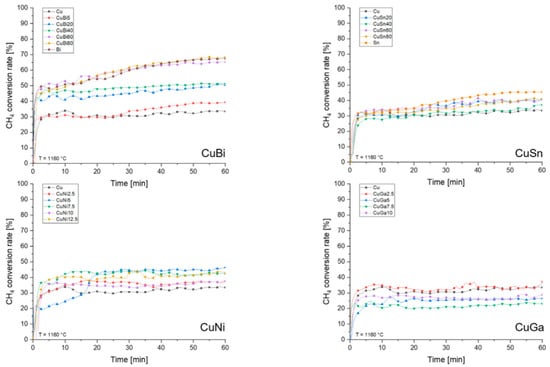
Figure 8.
Methane conversion rates for different investigated binary copper alloys over experimental duration at a process temperature of 1160 °C and a CH4 flow rate of 500 mln/min. (Used with permission from Ref. [52]. Copyright 2023, Elsevier.)
3.1.3. Other Catalysts
Metals with strong catalytic properties, like nickel, platinum, and palladium, have high melting points (>1400 °C), which limits their large-scale use. One promising solution is to combine these active metals with low-melting-point metals to form alloys suitable for CDM applications. Between 1978 and 1981, tellurium was tested as a molten catalyst. Tellurium, previously studied for dehydrogenating polynuclear hydrocarbons, was found to have a catalytic effect due to its high ionization potential, which facilitated electron transfer from tetralin to tellurium, stabilizing the system [53]. Later, tellurium was explored both experimentally and computationally for methane pyrolysis. The apparent activation energy for molten tellurium was determined to be 166 kJ/mol, with methane conversion rates ranging from 7% to 22% at temperatures between 897 and 987 °C. Quantum mechanical and ab initio molecular dynamics calculations were used to investigate methane activation on liquid tellurium, focusing on the C-H bond cleavage. The calculations showed that the lowest energy configuration occurred when both CH3 and H species were bonded to a single Te atom on the liquid surface, and the energy profile matched the observed activation energy.
In 1999, M. Steinberg [54] introduced the concept of a bubbling bath TCM reactor, which utilized a molten-metal bath like tin or copper to efficiently transfer heat to the methane gas flow. In 2008, Wang et al. [55] developed a high-temperature homogeneous catalytic system using molten magnesium as a catalyst to produce CO-free hydrogen and amorphous carbon. In 2015, Geißler, T. et al. [56] found that the methane conversion rate of metallic Sn was 45%, and that it would corrode the stainless-steel reactor. The carbon generated in the experiment primarily appeared as fine powder above the metal surface, without obstructing the reactor. In the same year, M. Plevan [57] and his team studied hydrogen production from methane pyrolysis in a metal bubble column reactor. The experiment took place in a stainless-steel tube reactor, filled with liquid tin, with an inner diameter of 35.9 mm and a total length of 1150 mm. Methane was injected from the bottom, and the temperature was varied between 700 °C and 950 °C. The study revealed that increasing the reactor temperature and decreasing the flow rate led to higher levels of methane conversion. Although the thermochemical model generally matched the experimental results, at low flow rates and 900 °C, the experimental results were lower than the model predictions. The findings indicated that liquid tin does not catalyze methane decomposition but helps reduce the formation of intermediate products. Further model improvements are needed to better understand the process and advance technological development. In 2016, Alberto Abnades et al. [58] used a reactor design suitable for the combination of glass and stainless-steel materials to avoid the corrosion problem of liquid metal relative to traditional steel. The methane conversion rate of this reaction was about 32.5%, and no intermediate products were obtained.
In 2008, Wang, K. et al. [55] explored the use of molten magnesium in stainless-steel reactors for breaking down hydrocarbons, waste polyolefins, and asphalt, achieving nearly 20% methane conversion at a relatively low temperature of 700 °C. Additionally, in situ FTIR spectra analysis revealed the presence of Mg2C3 species during methane decomposition at 400 °C, indicating that carbides played a role as intermediates in the reaction. The catalytic efficiency of molten magnesium in cracking processes was linked to its electronic properties. Magnesium’s higher electronegativity compared to hydrogen and carbon was thought to help break C-C and C-H bonds. As hydrogen gas formed and magnesium carbides decomposed, metallic magnesium was believed to regenerate and participate in further catalytic cycles (Figure 9).
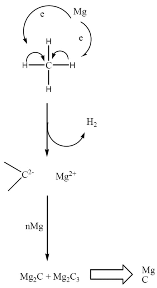
Figure 9.
Scheme of the proposed mechanism for carbon formation from methane and other hydrocarbons in molten magnesium. (Used with permission from Ref. [55]. Copyright 2008, Elsevier.)
Gallium has also been explored for its catalytic role in methane pyrolysis. In one study [59], methane conversion rates in the molten gallium were found to be surprisingly similar to those in the homogeneous gas phase, despite a much shorter residence time in the molten medium. This suggested that gallium may possess catalytic activity. In another study [60], gallium’s activity was compared with other metals such as tin, bismuth, indium, and copper, with gallium showing the lowest activation energy. Gallium’s catalytic effectiveness in methane pyrolysis was attributed to its lower first ionization energy. It was also tested for graphene production from methane in chemical vapor deposition, demonstrating strong performance. Brandon Jose Leal Perez and colleagues assessed hydrogen production from methane pyrolysis in a molten-metal bubble column reactor, using molten gallium as both the catalyst and heat transfer medium. The study achieved a methane conversion rate of 91% at 1119 °C. Economic analysis indicated that if the carbon by-product could be sold and a 50 euro per ton CO2 tax imposed, this technology could be competitive with steam methane reforming (SMR). The study emphasized that the economic viability of methane pyrolysis depends on carbon quality and process integration, with sensitivity analysis showing that carbon partial combustion and electricity usage are competitive options in various scenarios, offering flexibility.
Upham, D.C. et al. [46] explored the electronic properties of molten Pt–Bi and Pt–Sn alloys through ab initio simulations at a constant temperature. Their results indicated that the enhanced catalytic activity in these alloys is associated with a reduction in the negative charge on the active atoms, caused by interactions between the alloy components. As a result, Pt atoms in the alloys exhibited a slightly more positive Bader charge when anchored on FeOx, compared to their pure molten state. This charge transfer, similar to what is observed in single-atom heterogeneous catalysis, occurs due to the difference in chemical potentials between the metal atoms and supports [30].
A key challenge in utilizing molten alloys for methane pyrolysis is the formation of small metal clusters, which tend to aggregate due to the lower free energy on the metal surface. This aggregation can lower catalyst activity and efficiency. A study [22] examined the stability of Pt2 and Pt8 clusters in molten tin at 627 °C, finding that Pt–Pt bonds weakened, leading to the dissociation of the clusters. This was due to Sn electrons filling Pt antibonding orbitals, leading to the formation of Pt-1 ions. Sintering at elevated temperatures (e.g., >600 °C in molten salt reactors) induces irreversible aggregation of metal nanoparticles (Ni, Fe, and Co) via particle migration and Ostwald ripening, drastically reducing active surface area and eroding critical edge/step sites needed to nucleate carbon nanotubes (CNTs)—instead favoring amorphous carbon. Overly high metal loading (>10 wt%) exacerbates this by promoting poor dispersion and particle crowding during impregnation, which impedes gas diffusion in molten salts (e.g., CH4 → H2 + C) and shifts CNT growth mechanisms from efficient tip-growth to base-growth with encapsulated, deactivated metal cores. Critically, the preparation method dictates initial catalyst architecture: impregnation often yields non-uniform particles prone to sintering, while colloidal synthesis or deposition–precipitation enables size-controlled nanoparticles (3–8 nm) with tailored morphologies (cubes, octahedra). These morphologies—combined with electron configuration (e.g., high d-band Ni)—direct carbon diffusion paths, steering growth toward specific allotropes (CNTs on Ni(111) facets vs. graphene on Cu(100)). Thus, mitigating sintering via optimal loading (5–8 wt%) and advanced preparation (e.g., molten salt-confined nanoparticles) is essential to preserve active sites and achieve crystalline carbon structures under harsh reaction regimes.
Erbasan et al. [50] explored the effect of adding Al and Cu as promoters to Bi–Ni alloys. They observed that incorporating 10–20% promoters enhanced performance compared to the Ni–Bi binary alloy. Al played a significant role in direct catalysis, while Cu influenced Ni’s performance indirectly through charge transfer.
Kim, T. et al. [61] investigated bismuth-based binary molten alloy catalysts for methane pyrolysis aimed at producing CO2-free hydrogen. They found that the Zn0.45-Bi0.55 alloy exhibited the highest catalytic activity among 20 binary alloys, with a reduced free energy barrier for the initial C-H bond activation; they used density functional theory (DFT) and meta-dynamics (MTD) simulations to determine that methane activation followed the surface stabilization path, instead of the free radical path. The experimental data showed an apparent activation energy of 157.0 kJ/mol for the process Zn0.45-Bi0.55 alloy, significantly lower than that of pure bismuth (308.7 kJ/mol). The experimental temperature range of Bi in this literature is 750–900 °C, while that of the Zn0.45Bi0.55 alloy is 650–800 °C. Kinetic measurements suggested a reaction order close to first order. Carbon analysis showed a partly crystalline structure, indicating the alloy’s potential for use as a high-value carbon material.
3.2. Molten Salt
The grain size of carbon is small, suggesting that the growth of carbon in the NaCl reaction bed is to some extent inhibited. Kang, D. et al. [62] studied the process of catalytic methane pyrolysis using a molten mixture of MnCl2 and KCl to produce hydrogen and solid carbon. The activity of pure KCl was low, while that of the MnCl2-KCl mixture was significantly enhanced. The apparent activation energy decreased from about 300 kJ/mol for pure KCl to 161 kJ/mol for the 67:33 MnCl2-KCl mixture. The carbon produced by the MnCl2-KCl mixture catalyst has a highly graphitized structure, while the carbon produced by pure KCl is more amorphous. The stability of this catalyst can last for more than 30 h (Figure 10). Kang, D. et al. [63] researched the addition of iron(III) chloride (FeCl3) to molten alkali metal chloride salts, which significantly enhances the catalytic activity of methane pyrolysis. The presence of iron may promote the activation of C-H bonds by forming stable molecular ions such as FeCl4−. The catalytic activity is enhanced, with the apparent activation energy of methane pyrolysis decreasing from 301 kJ/mol to 171 kJ/mol after the addition of 3 wt% FeCl3 to the molten NaCl-KCl salt. The presence of iron leads to the formation of solid carbon with a graphite structure, which is different from the more disordered carbon formed in the iron-free molten salt, indicating different carbon formation pathways. Through Arrhenius plot analysis, the reaction kinetic parameters at different iron contents were determined. The apparent activation energy decreases with the increase of iron content, while the pre-exponential factor decreases, suggesting a shift in the reaction path from gas-phase collision to surface-mediated catalysis. At 1000 °C, the rate constant of Fe(3%)/NaKCl is 0.088–0.099 s−1, showing a high reaction rate. The experiments were conducted using a differential bubble column reactor with an inner diameter of 2.5 cm and a filling height of 12.5 cm, and the reaction temperature was controlled between 700 and 1050 °C. The residence time of the bubbles in the melt was approximately 0.5 s, and the bubble rising velocity was about 23 cm/s. The reaction gas was injected into the melt through a quartz capillary. The generated solid carbon has two structures: flaky and spherical. The flaky carbon has a graphite structure, while the spherical carbon is more disordered. The purity of the carbon product is over 90 atomic%, and the carbon in Fe(3%)/NaKCl contains detectable iron. After continuous operation at 1000 °C for 50 h, the methane conversion rate of Fe(3%)/NaKCl remains stable, demonstrating good long-term stability. No X-ray diffraction peaks of metallic iron were observed in the rapidly cooled melt, indicating that the iron mainly exists in the form of molecular ions (Figure 11). Seo, J.-C. et al. researched [48] the situation of methane pyrolysis using molten NaCl, which was studied and analyzed in detail. When pure NaCl was used as the reaction bed, the conversion rate of methane was relatively low. Molten NaCl itself has weak catalytic activity for methane decomposition, and its main role is to promote the decomposition of methane through physical properties such as heat transfer capacity and the solubility of carbon or hydrogen. At high temperatures, the catalytic activity of NaCl may increase due to the influence of a thermodynamic driving force. The carbon products generated by the NaCl reaction bed have a low metal content but a high salt content. This may be due to the fact that the NaCl layer adsorbs some metal impurities during the reaction process. The purity of carbon can be further improved through subsequent acid washing and water washing treatments. Through Raman spectroscopy analysis, the carbon produced by the NaCl reaction bed shows a high degree of disorder (with a high ID/IG value), indicating that its structure is closer to that of amorphous carbon. M. McConnachie [64] researched catalyst materials such as MoS2, WS2, WC, and Al2O3, which were selected and suspended in the NaBr-KBr molten salt for experiments. A vertical quartz tube reactor was used, with pure methane bubbles introduced at the bottom and molten salt slurry catalyst filled at the top. The reactor was preheated to 750 °C in an argon atmosphere, and then the temperature was gradually increased to 800 °C and kept constant prior to the introduction of methane for the pyrolysis reaction. The pyrolysis reaction was carried out by introducing methane at a constant flow rate for 6 h. After the reaction was completed, the reactor was cooled and the salt–carbon-catalyst complex was taken out. It was washed and filtered with diluted nitric acid to remove unreacted substances and soluble impurities. Four stability tests were conducted at 800 °C. The results showed that MoS2 exhibited a high methane conversion rate in the NaBr-KBr molten salt, reaching 2.75%, and had good structural stability, mainly through coking deactivation. Through BET analysis, it was found that the surface areas of WS2, MoS2 and WC changed little, while the surface area of Al2O3 decreased from 130 m2/g to 91 m2/g, indicating that partial deactivation might be due to coke formation. In the same year, Wang, C. et al. [65] researched ternary molten carbonates, which were prepared by mixing Li2CO3, Na2CO3, and K2CO3 in a mass ratio of 3:3:4. The Ni/Al2O3 catalyst was prepared through impregnation, calcination, and reduction steps. An iron bubble cap reactor with an inner diameter of 53 mm and an effective length of 245 mm was used, heated by an electric furnace and equipped with a PID controller. The ternary molten carbonate was mixed with 10 wt% Ni/Al2O3 and heated to 500 °C. After the addition of 10 g Ni/Al2O3 catalysts, the methane conversion rate reached 92.5%, while it was only 2% without the addition of catalysts. When the masses of the catalysts were 10 g and 20 g, the methane conversion rate exceeded 70%, while it was only 50% when they were 1 g and 2 g. Under optimal conditions, after continuous operation for 72 h, the conversion rate of the catalyst addition system gradually decreased by approximately 5% after 54 h, while that of the molten salt system gradually decreased by 1% after 66 h. This is shown in Table 1.
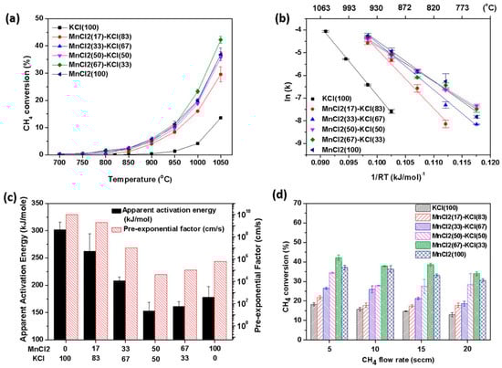
Figure 10.
Activity of molten MnCl2-KCl for CH4 pyrolysis. (a) CH4 conversion versus temperature for a MnCl2-KCl bubble column. Melt height 12.5 cm, reactant gas = 20 sccm (50 mol% of CH4 and 50 mol% of Ar), sweep gas = 50 sccm (100 mol% of Ar). (b) Arrhenius plot for apparent activation energies for methane consumption rate, catalyzed by MnCl2-KCls. (c) Comparison of apparent activation energies and pre-exponential factors of the molten MnCl2-KCl mixtures. (d) CH4 conversion versus CH4 flow rate for a 12.5 cm molten MnCl2-KCl bubble column at 1050 °C: reactant gas (100 mol% of CH4), sweep gas = 50 sccm (100 mol% of Ar). (Used with permission from Ref. [62]. Copyright 2019, Elsevier.)
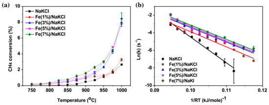
Figure 11.
Catalytic activity of Fe/NaKCls for methane pyrolysis: 20 sccm of reactant gas (CH4:Ar= 50:50 vol %) and 50 sccm of sweep gas (100 vol % of Ar). (a) Methane conversion versus temperature. (b) Arrhenius plots for methane consumption rate measured in differential reactor. (Used with permission from Ref. [63]. Copyright 2020, Elsevier.)

Table 1.
Summary of recent TDM studies (from year 2019 to present) on turquoise H2 production from the literature. (Used with permission from Ref. [66]. Copyright 2024, Elsevier.)
Eutectic engineering (e.g., NaCl-KCl-ZnCl2) lowers operating temperatures to 600 °C, reducing evaporation losses. The harvested carbon nanostructures exhibit tunable properties: amorphous flakes for cement additives (from molten salts) vs. graphitic spheres for battery anodes (from molten metals). Reactor configurations critically impact efficiency—bubble columns enhance gas–liquid contact but entrain fine carbon, while rotating disk reactors achieve 95% carbon separation efficiency via centrifugal forces. Future work should optimize solidification pathways for high-value carbon products. Table 2 presents the performance of molten catalysts.
Table 2.
Molten catalysts: Performance.
Extensive research has been conducted to elucidate methane pyrolysis reactions and to develop kinetic models for the various reactor systems and catalysts used. The availability of kinetic models provides valuable insights into the mechanisms, rates, and activation energies that represent the barriers to reaction-generating energy that must be overcome. Kinetic models allow prediction and estimation of reaction rates under different conditions. By combining experimental data with theoretical principles, these models can provide information about the dependence of reaction rates on factors such as temperature, pressure, and reactant concentration. In addition, through a quantitative understanding of the kinetic parameters and their effects on the reaction rate, the researchers can use this information to predict efficient methane pyrolysis processes aimed at maximizing hydrogen production. This knowledge helps develop strategies to improve reactor design, catalyst performance and process conditions for a more sustainable and economically viable methane pyrolysis process. Table 3 summarizes a comprehensive review of studies relevant to determining the effects of reactor design, catalyst, and operating conditions on kinetic modeling and parameters.
Table 3.
Overview of kinetic studies on methane pyrolysis using various reactor types, catalysts, and operating conditions.(Used with permission from Ref. [66]. Copyright 2024, Elsevier.)
4. Economic and Environmental Benefits
While technically feasible, the commercial viability of CH4 pyrolysis for H2 and carbon production depends critically on its economics. Some existing techno-economic analyses (TEA) assess this potential (Table 4). Pérez et al. [35] evaluated an industrial molten gallium bubble reactor concept for thermal methane decomposition (TDM), examining different pyrolysis reactor heat sources: (1) carbon combustion ± CCS, (2) H2 combustion, (3) NG combustion ± CCS, and (4) electricity. Their levelized cost of hydrogen (LCOH) analysis found cases 1 (2.94 €/kg H2) and 4 (3.16 €/kg H2) competitive with benchmark SMR without CCS (2.86 €/kg H2). Case 2 had the highest LCOH (4.03 €/kg H2), due to the substantial natural gas requirements in producing H2 for reactor heating while meeting the H2 output. Environmentally and economically, cases 1 (with CCS) and 4 were superior to non-CCS SMR, offering lower CO2 emissions and carbon tax burdens. Pérez et al. also identified NG price and carbon sales price as key economic feasibility determinants for pyrolysis versus SMR through sensitivity analysis (Figure 12).
Table 4.
Summary of TEA on CH4 pyrolysis, from the literature. (Used with permission from Ref. [66]. Copyright 2024, Elsevier.)
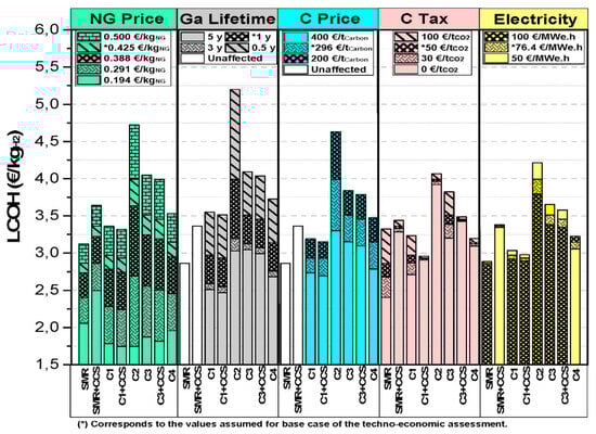
Figure 12.
Sensitivity analyses of the key parameters on the LCOH of CH4 pyrolysis for various case scenarios. Reprinted with permission. (Used with permission from Ref. [35]. Copyright 2022, Elsevier.)
Kerscher et al. [95] and Riley et al. [96] performed techno-economic analyses (TEA) on thermal methane decomposition (TDM) using distinct reactor types: an electron beam plasma reactor and a catalytic fluidized bed reactor, respectively. Both studies examined heat/electricity supply options similar to Pérez et al. [35], utilizing produced H2 or alternative sources like renewables or natural gas (NG). For the electron beam plasma approach, the lowest levelized cost of hydrogen (LCOH) was 2.55 €/kg H2. While this exceeded conventional SMR costs (1.00–1.18 €/kg H2, with/without CCS), it was lower than water electrolysis (4.31 €/kg H2). The high electrolysis cost stems from its greater energy demand (286.0 kJ/mol H2 vs. 37.5 kJ/mol H2 for CH4 splitting). The study attributed the plasma process’s high capital expenditure (CAPEX) mainly to expensive electron accelerators, which contributed over 50% of the LCOH. However, future advancements in plasma technology could potentially reduce CAPEX and lower LCOH below 1.5 €/kg H2 [95]. Riley et al. [96] estimated an LCOH range of USD 2.94–3.1/kg H2 for pyrolysis without carbon revenue. Including carbon sales revenue could reduce LCOH to near USD 0/kg H2. Pruvost et al. [97] investigated molten salt bubble column reactor operating conditions, uniquely estimating the levelized cost of carbon (LCOC) against a fixed H2 price (1.6 €/kg). At optimal conditions (12 bar, 100 °C approach temperature), the lowest LCOC was 306 €/ton, rising by 24% to 379 €/ton after accounting for carbon post-treatment [97].
Tabat et al. [98] introduced a profitable mobile autothermal methane pyrolysis unit to overcome hydrogen pipeline limitations. Energy/exergy analyses assessed its efficiency. Economic evaluation yielded an LCOH of USD 1.3–1.47/kg H2 and an NPV of USD 3.76–4.35 million, influenced by EPC and feedstock costs. The positive NPV and competitive LCOH, alongside a high CH4 conversion rate (76.8%), confirmed the design’s profitability. Cheon et al. [99] comprehensively compared hydrogen production systems, analyzing unit costs relative to commercial methods. Technical assessment considered H2 and carbon output, H2 combustion ratio, and reactant ratios. Unit hydrogen production costs varied between USD 2.14 and 3.82/kg across configurations.
These TEA studies collectively highlight that commercial CH4 pyrolysis deployment critically depends on revenue from co-produced carbon. Achieving H2 prices competitive with conventional SMR requires a viable carbon market to enhance the technology’s economic viability. Furthermore, diverting produced H2 for reactor heating is widely deemed uneconomical, due to significant natural gas consumption and the challenge of marketing large quantities of carbon.
5. Conclusion and Prospects
Despite a century of research, methane pyrolysis catalysis remains constrained by factors defining a tripartite paradox: the need to simultaneously achieve high activity (>90% CH4 conversion), development of the potential of coke resistance (>1000 h stability), and economic viability ($ < 2/kg H2). Solid catalysts face intrinsic deactivation cascades from carbon encapsulation (TOF attenuation > 80% in <10 h), sintering-induced structural collapse, and carbide formation—fundamentally rooted in Sabatier principle-based limitations in that active sites optimize either CH4 adsorption or C desorption, but not both. Molten systems circumvent coking through buoyant carbon rejection (Δρ > 2 g/cm3) yet confront corrosive/thermal challenges (T > 1000 °C induces reactor erosion rates > 1 mm/year). Regeneration strategies paradoxically increase the carbon footprint (CO2eq increased emissions 15–30%) while degrading catalyst crystallinity (XRD FWHM broadening ≥ 0.5°).
Critical breakthroughs demand the following:
- Operando DFT-ML co-design revealing d-orbital modulation thresholds for CH4 →H2 transition states (ΔE < 1.2 eV);
- Eutectic engineering of ZnCl2-NaCl-KCl molten salts (Tm increase 600 °C) coupled with plasmonic excitation (λ = 800 nm) to overcome thermodynamic penalties;
- Carbon valorization 3.0 strategies converting turbostratic by-products into graphene-enhanced cement (compressive strength increases 40%) or microbial fuel cell anodes (watt density > 2 W/m2);
- Reactor designs integrating microwave-assisted cracking (ηenergy increase 25%) with semi-continuous carbon skimming (separation efficiency > 98%);
- Technoeconomic recalibration valuing carbon credits ($50/ton) and grid-balancing H2 storage premiums.
Integrating reaction engineering, circular material flows, and energy system dynamics, this challenge requires the convergence of surface science, AI-driven high-throughput synthesis (10 samples per day), and policy-driven carbon markets. While molten catalysts exhibit the potential for coke resistance due to buoyant carbon removal, degradation from fine carbon (<10 μm) remains a challenge requiring advanced separation systems.
Author Contributions
Writing—original draft preparation X.Y.; methodology, writing—review and editing X.Y., C.Z. and C.S.; resources, Q.X., H.C., X.L. and X.Z. All authors have read and agreed to the published version of the manuscript.
Funding
This research was funded by Qian Xu grant number [51574163].
Conflicts of Interest
The authors declare no conflicts of interest.
References
- Li, G.; Xu, S.; Tang, Y.; Wang, Y.; Lou, J.; Zhang, Q.; Zheng, X.; Li, J.; Iqbal, B.; Cheng, P.; et al. Spartina alterniflora invasion altered soil greenhouse gas emissions via affecting labile organic carbon in a coastal wetland. Appl. Soil Ecol. 2024, 203, 105615. [Google Scholar] [CrossRef]
- Cui, M.; Wang, J.; Zhang, X.; Wang, C.; Li, G.; Wan, J.S.H.; Du, D. Warming significantly inhibited the competitive advantage of native plants in interspecific competition under phosphorus deposition. Plant Soil 2023, 486, 503–518. [Google Scholar] [CrossRef]
- Bankole, O.O.; Danso, F.; Zhang, N.; Zhang, J.; Zhang, K.; Dong, W.; Lu, C.; Zhang, X.; Li, G.; Raheem, A.; et al. Integrated Effects of Straw Incorporation and N Application on Rice Yield and Greenhouse Gas Emissions in Three Rice-Based Cropping Systems. Agronomy 2024, 14, 490. [Google Scholar] [CrossRef]
- Raza, S.; Irshad, A.; Margenot, A.; Zamanian, K.; Li, N.; Ullah, S.; Mehmood, K.; Khan, M.A.; Siddique, N.; Zhou, J.; et al. Inorganic carbon is overlooked in global soil carbon research: A bibliometric analysis. Geoderma 2024, 443, 116831. [Google Scholar] [CrossRef]
- Khan, I.; Tariq, M.; Alabbosh, K.F.; Rehman, A.; Jalal, A.; Khan, A.A.; Farooq, M.; Li, G.; Iqbal, B.; Ahmad, N.; et al. Soil microplastics: Impacts on greenhouse gasses emissions, carbon cycling, microbial diversity, and soil characteristics. Appl. Soil. Ecol. 2024, 197, 105343. [Google Scholar] [CrossRef]
- Zhang, J.; Ren, M.; Li, X.; Hao, Q.; Chen, H.; Ma, X. Ni-based catalysts prepared for CO2 reforming and decomposition of methane. Energy Convers. Manag. 2020, 205, 112419. [Google Scholar] [CrossRef]
- Dantas, S.C.; Escritori, J.C.; Soares, R.R.; Hori, C.E. Effect of different promoters on Ni/CeZrO2 catalyst for autothermal reforming and partial oxidation of methane. Chem. Eng. J. 2010, 156, 380–387. [Google Scholar] [CrossRef]
- Catumba, B.D.; Sales, M.B.; Borges, P.T.; Filho, M.N.R.; Lopes, A.A.S.; Rios, M.A.D.S.; Desai, A.S.; Bilal, M.; Santos, J.C.S.D. Sustainability and challenges in hydrogen production: An advanced bibliometric analysis. Int. J. Hydrogen Energy 2023, 48, 7975–7992. [Google Scholar] [CrossRef]
- Avargani, V.M.; Zendehboudi, S.; Saady, N.M.C.; Dusseault, M.B. A comprehensive review on hydrogen production and utilization in North America: Prospects and challenges. Energy Convers. Manag. 2022, 269, 115927. [Google Scholar] [CrossRef]
- Santos, D.M.F.; Sequeira, C.A.C.; Figueiredo, J.L. Hydrogen production by alkaline water electrolysis. Química Nova 2013, 36, 1176–1193. [Google Scholar] [CrossRef]
- Dagle, R.A.; Dagle, V.; Bearden, M.D.; Holladay, J.D.; Krause, T.R.; Ahmed, S. An Overview of Natural Gas Conversion Technologies for Co-Production of Hydrogen and Value-Added Solid Carbon Products; U.S. Department of Energy Office of Scientific and Technical Information: Oak Ridge, TN, USA, 2017. [CrossRef]
- Hang, Z.A.; Zhou, Y.X.; Zhang, K.K.; Liu, M.Y.; Yang, M.K.; Zhan, J.J.; Liu, T.; Zhou, Y. Research Progress on Methane Pyrolysis Process for Hydrogen and Carbon Materials. Low-Carbonization Sci. Chem. Eng. 2024, 49, 1–11. [Google Scholar] [CrossRef]
- Al-Rumaihi, A.; Shahbaz, M.; McKay, G.; Mackey, H.; Al-Ansari, T. A review of pyrolysis technologies and feedstock: A blending approach for plastic and biomass towards optimum biochar yield. Renew. Sustain. Energy Rev. 2022, 167, 112715. [Google Scholar] [CrossRef]
- Cui, K. Research Status of Hydrogen Production from Methane Catalytic Cracking. Guangzhou Chem. Ind. 2022, 50, 44–46. [Google Scholar]
- Bayat, N.; Rezaei, M.; Meshkani, F. Methane decomposition over Ni–Fe/Al2O3 catalysts for production of COx-free hydrogen and carbon nanofiber. Int. J. Hydrogen Energy 2016, 41, 1574–1584. [Google Scholar] [CrossRef]
- Bayat, N.; Rezaei, M.; Meshkani, F. Hydrogen and carbon nanofibers synthesis by methane decomposition over Ni–Pd/Al2O3 catalyst. Int. J. Hydrogen Energy 2016, 41, 5494–5503. [Google Scholar] [CrossRef]
- Timmerberg, S.; Kaltschmitt, M.; Finkbeiner, M. Hydrogen and hydrogen-derived fuels through methane decomposition of natural gas–GHG emissions and costs. Energy Convers. Manag. X 2020, 7, 100043. [Google Scholar] [CrossRef]
- Prabowo, J.; Lai, L.; Chivers, B.; Burke, D.; Dinh, A.H.; Ye, L.; Wang, Y.; Wang, Y.; Wei, L.; Chen, Y. Solid carbon co-products from hydrogen production by methane pyrolysis: Current understandings and recent progress. Carbon 2024, 216, 118507. [Google Scholar] [CrossRef]
- Mohammed, S.; Eljack, F.; Al-Sobhi, S.; Kazi, M.-K. A systematic review: The role of emerging carbon capture and conversion technologies for energy transition to clean hydrogen. J. Clean. Prod. 2024, 447, 141506. [Google Scholar] [CrossRef]
- Sharma, S.; Ivanov, A.S.; Margulis, C.J. A Brief Guide to the Structure of High-Temperature Molten Salts and Key Aspects Making Them Different from Their Low-Temperature Relatives, the Ionic Liquids. J. Phys. Chem. B 2021, 125, 6359–6372. [Google Scholar] [CrossRef]
- McConnachie, M.; Konarova, M.; Smart, S. Literature review of the catalytic pyrolysis of methane for hydrogen and carbon production. Int. J. Hydrogen Energy 2023, 48, 25660–25682. [Google Scholar] [CrossRef]
- Zaghloul, N.; Kodama, S.; Sekiguchi, H. Hydrogen Production by Methane Pyrolysis in a Molten-Metal Bubble Column. Chem. Eng. Technol. 2021, 44, 1986–1993. [Google Scholar] [CrossRef]
- Tian, M.Y.; Wang, Y.; Sun, X.; Fu, J.; Lu, L.; Li, H. Research Progress on Liquid Metal Catalysts for Methane Cracking to Produce Hydrogen. Low-Carbonization Sci. Chem. Eng. 2025, 50, 148–156. [Google Scholar] [CrossRef]
- Sánchez-Bastardo, N.; Schlögl, R.; Ruland, H. Methane Pyrolysis for Zero-Emission Hydrogen Production: A Potential Bridge Technology from Fossil Fuels to a Renewable and Sustainable Hydrogen Economy. Ind. Eng. Chem. Res. 2021, 60, 11855–11881. [Google Scholar] [CrossRef]
- Grabke, H.J. Evidence on the surface concentration of carbon on gamma iron from the kinetics of the carburization in CH4−H2. Metall. Trans. 1970, 1, 2972–2975. [Google Scholar] [CrossRef]
- Cao, M.J.; Nie, L.F.; Li, S.D.; Chen, Y.F. Research progress on hydrogen production from catalytic cracking of methane. Appl. Chem. Eng. 2023, 52, 2218–2224. [Google Scholar]
- Patlolla, S.R.; Katsu, K.; Sharafian, A.; Wei, K.; Herrera, O.E.; Mérida, W. A review of methane pyrolysis technologies for hydrogen production. Renew. Sustain. Energy Rev. 2023, 181, 113323. [Google Scholar] [CrossRef]
- Msheik, M.; Rodat, S.; Abanades, S. Methane Cracking for Hydrogen Production: A Review of Catalytic and Molten Media Pyrolysis. Energies 2021, 14, 3107. [Google Scholar] [CrossRef]
- Liao, J.S.; Liu, J.X.; Wang, S.S.; Chen, B.; Chen, J.J.; Wei, J.J.; Ye, Z.B.; Gou, F.J. Kinetics of Methane Decomposition in the Catalytic Liquid Metal Reactor for Hydrogen Production. Acta Chim. Sin. High. Educ. Inst. 2024, 45, 62–68. [Google Scholar]
- Busillo, E.; Damizia, M.; De Filippis, P.; de Caprariis, B. Methane pyrolysis in molten media: The interplay of physical properties and catalytic activity on carbon and hydrogen production. J. Anal. Appl. Pyrolysis 2024, 183, 106752. [Google Scholar] [CrossRef]
- McConnachie, M.; Yan, P.; Konarova, M.; Smart, S. Methane pyrolysis in molten salt slurry systems: Evaluation of activity and mechanism in binary salt mixtures with molybdenum disulfide suspensions. Int. J. Hydrogen Energy 2024, 81, 1172–1180. [Google Scholar] [CrossRef]
- Gunarayu, M.R.; Patah, M.F.A.; Daud, W.M.A.W. Advancements in methane pyrolysis: A comprehensive review of parameters and molten catalysts in bubble column reactors. Renew. Sustain. Energy Rev. 2025, 210, 115197. [Google Scholar] [CrossRef]
- Musamali, R.; Isa, Y.M. Decomposition of Methane to Carbon and Hydrogen: A Catalytic Perspective. Energy Technol. 2019, 7, 1800593. [Google Scholar] [CrossRef]
- Neuschitzer, D.; Scheiblehner, D.; Antrekowitsch, H.; Wibner, S.; Sprung, A. Methane Pyrolysis in a Liquid Metal Bubble Column Reactor for CO2-Free Production of Hydrogen. Energies 2023, 16, 7058. [Google Scholar] [CrossRef]
- Pérez, B.J.L.; Jiménez, J.A.M.; Bhardwaj, R.; Goetheer, E.; van Sint Annaland, M.; Gallucci, F. Methane pyrolysis in a molten gallium bubble column reactor for sustainable hydrogen production: Proof of concept & techno-economic assessment. Int. J. Hydrogen Energy 2021, 46, 4917–4935. [Google Scholar] [CrossRef]
- Geißler, T.; Abánades, A.; Heinzel, A.; Mehravaran, K.; Müller, G.; Rathnam, R.K.; Rubbia, C.; Salmieri, D.; Stoppel, L.; Stückrad, S.; et al. Hydrogen production via methane pyrolysis in a liquid metal bubble column reactor with a packed bed. Chem. Eng. J. 2016, 299, 192–200. [Google Scholar] [CrossRef]
- Toncu, D.C.; Toncu, G.; Soleimani, S. On methane pyrolysis special applications. IOP Conf. Ser. Mater. Sci. Eng. 2015, 95, 012026. [Google Scholar] [CrossRef]
- Becker, T.; Richter, M.; Agar, D.W. Methane pyrolysis: Kinetic studies and mechanical removal of carbon deposits in reactors of different materials. Int. J. Hydrogen Energy 2023, 48, 2112–2129. [Google Scholar] [CrossRef]
- Schultz, I.; Agar, D.W. Decarbonisation of fossil energy via methane pyrolysis using two reactor concepts: Fluid wall flow reactor and molten metal capillary reactor. Int. J. Hydrogen Energy 2015, 40, 11422–11427. [Google Scholar] [CrossRef]
- Mohagheghian, S.; Elbing, B.R. Characterization of Bubble Size Distributions within a Bubble Column. Fluids 2018, 3, 13. [Google Scholar] [CrossRef]
- Rahimi, N.; Kang, D.; Gelinas, J.; Menon, A.; Gordon, M.J.; Metiu, H.; McFarland, E.W. Solid carbon production and recovery from high temperature methane pyrolysis in bubble columns containing molten metals and molten salts. Carbon 2019, 151, 181–191. [Google Scholar] [CrossRef]
- Maalej, S.; Benadda, B.; Otterbein, M. Influence of Pressure on the Hydrodynamics and Mass Transfer Parameters of an Agitated Bubble Reactor. Chem. Eng. Technol. 2001, 24, 77–84. [Google Scholar] [CrossRef]
- Daeneke, T.; Khoshmanesh, K.; Mahmood, N.; de Castro, I.A.; Esrafilzadeh, D.; Barrow, S.J.; Dickey, M.D.; Kalantar-zadeh, K. Liquid metals: Fundamentals and applications in chemistry. Chem. Soc. Rev. 2018, 47, 4073–4111. [Google Scholar] [CrossRef]
- Yang, X.-F.; Wang, A.; Qiao, B.; Li, J.; Liu, J.; Zhang, T. Single-Atom Catalysts: A New Frontier in Heterogeneous Catalysis. Acc. Chem. Res. 2013, 46, 1740–1748. [Google Scholar] [CrossRef]
- Fan, Z.; Weng, W.; Zhou, J.; Gu, D.; Xiao, W. Catalytic decomposition of methane to produce hydrogen: A review. J. Energy Chem. 2021, 58, 415–430. [Google Scholar] [CrossRef]
- Upham, D.C.; Agarwal, V.; Khechfe, A.; Snodgrass, Z.R.; Gordon, M.J.; Metiu, H.; McFarland, E.W. Catalytic molten metals for the direct conversion of methane to hydrogen and separable carbon. Science 2017, 358, 917–921. [Google Scholar] [CrossRef]
- Zeng, J.; Tarazkar, M.; Pennebaker, T.; Gordon, M.J.; Metiu, H.; McFarland, E.W. Catalytic Methane Pyrolysis with Liquid and Vapor Phase Tellurium. ACS Catal. 2020, 10, 8223–8230. [Google Scholar] [CrossRef]
- Seo, J.-C.; Park, S.; Park, G.; Lee, Y.; Han, S.J.; Kim, S.K. Catalytic CH4 pyrolysis promoted by the interface of a molten metal–salt hybrid system. Gas Sci. Eng. 2023, 115, 205017. [Google Scholar] [CrossRef]
- Chen, L.; Song, Z.; Zhang, S.; Chang, C.-K.; Chuang, Y.-C.; Peng, X.; Dun, C.; Urban, J.J.; Guo, J.; Chen, J.-L.; et al. Ternary NiMo-Bi liquid alloy catalyst for efficient hydrogen production from methane pyrolysis. Science 2023, 381, 857–861. [Google Scholar] [CrossRef]
- Erbasan, A.; Ustunel, H.; Toffoli, D.; Gokalp, I.; Kardas, G.; Celik, G. Insights into Reaction Mechanisms in Liquid Metals from Density Functional Theory: CH4 Pyrolysis in BiNiX (X = Cu, Al) Molten Metals as a Case Study. ACS Appl. Energy Mater. 2024, 7, 3220–3233. [Google Scholar] [CrossRef]
- Palmer, C.; Tarazkar, M.; Kristoffersen, H.H.; Gelinas, J.; Gordon, M.J.; McFarland, E.W.; Metiu, H. Methane Pyrolysis with a Molten Cu–Bi Alloy Catalyst. ACS Catal. 2019, 9, 8337–8345. [Google Scholar] [CrossRef]
- Scheiblehner, D.; Neuschitzer, D.; Wibner, S.; Sprung, A.; Antrekowitsch, H. Hydrogen production by methane pyrolysis in molten binary copper alloys. Int. J. Hydrogen Energy 2023, 48, 6233–6243. [Google Scholar] [CrossRef]
- Takahashi, K.; Ogino, Y. Liquid tellurium as a catalyst for the dehydrogention of several polynuclear hydrocarbons. Chem. Lett. 2006, 7, 423–425. [Google Scholar] [CrossRef]
- Steinberg, M. Fossil fuel decarbonization technology for mitigating global warming. Int. J. Hydrogen Energy 1999, 24, 771–777. [Google Scholar] [CrossRef]
- Wang, K.; Li, W.S.; Zhou, X.P. Hydrogen generation by direct decomposition of hydrocarbons over molten magnesium. J. Mol. Catal. A Chem. 2008, 283, 153–157. [Google Scholar] [CrossRef]
- Geißler, T.; Plevan, M.; Abánades, A.; Heinzel, A.; Mehravaran, K.; Rathnam, R.K.; Rubbia, C.; Salmieri, D.; Stoppel, L.; Stückrad, S.; et al. Experimental investigation and thermo-chemical modeling of methane pyrolysis in a liquid metal bubble column reactor with a packed bed. Int. J. Hydrogen Energy 2015, 40, 14134–14146. [Google Scholar] [CrossRef]
- Plevan, M.; Geißler, T.; Abánades, A.; Mehravaran, K.; Rathnam, R.K.; Rubbia, C.; Salmieri, D.; Stoppel, L.; Stückrad, S.; Wetzel, T. Thermal cracking of methane in a liquid metal bubble column reactor: Experiments and kinetic analysis. Int. J. Hydrogen Energy 2015, 40, 8020–8033. [Google Scholar] [CrossRef]
- Abánades, A.; Rathnam, R.K.; Geißler, T.; Heinzel, A.; Mehravaran, K.; Müller, G.; Plevan, M.; Rubbia, C.; Salmieri, D.; Stoppel, L.; et al. Development of methane decarbonisation based on liquid metal technology for CO2-free production of hydrogen. Int. J. Hydrogen Energy 2016, 41, 8159–8167. [Google Scholar] [CrossRef]
- Maestre, V.M.; Ortiz, A.; Ortiz, I. Challenges and prospects of renewable hydrogen-based strategies for full decarbonization of stationary power applications. Renew. Sustain. Energy Rev. 2021, 152, 111628. [Google Scholar] [CrossRef]
- Wi, T.-G.; Park, Y.-J.; Lee, U.; Kang, Y.-B. Methane pyrolysis rate measurement using electromagnetic levitation techniques for turquoise hydrogen production: Liquid In, Ga, Bi, Sn, and Cu as catalysts. Chem. Eng. J. 2023, 460, 141558. [Google Scholar] [CrossRef]
- Kim, T.; Lee, J.; Ko, Y.; Chong, G.-H.; Kang, D.; Kwon, H. Catalytic molten Zn-Bi alloys for methane pyrolysis. Chem. Eng. J. 2025, 509, 161304. [Google Scholar] [CrossRef]
- Kang, D.; Rahimi, N.; Gordon, M.J.; Metiu, H.; McFarland, E.W. Catalytic methane pyrolysis in molten MnCl2-KCl. Appl. Catal. B Environ. 2019, 254, 659–666. [Google Scholar] [CrossRef]
- Kang, D.; Palmer, C.; Mannini, D.; Rahimi, N.; Gordon, M.J.; Metiu, H.; McFarland, E.W. Catalytic Methane Pyrolysis in Molten Alkali Chloride Salts Containing Iron. ACS Catal. 2020, 10, 7032–7042. [Google Scholar] [CrossRef]
- McConnachie, M.; Sheil, A.; Konarova, M.; Smart, S. Evaluation of heterogeneous metal-sulfide molten salt slurry systems for hydrogen production through methane pyrolysis. Int. J. Hydrogen Energy 2024, 49, 981–991. [Google Scholar] [CrossRef]
- Wang, C.; Zhan, F.; Wang, S.; Wei, Y.; Ji, J. Molten salts coupled Ni/Al2O3 for hydrogen from CH4 pyrolysis at mild temperature in bubble-cap reactor. Fuel 2024, 368, 131612. [Google Scholar] [CrossRef]
- Chan, Y.H.; Chan, Z.P.; Lock, S.S.M.; Yiin, C.L.; Foong, S.Y.; Wong, M.K.; Ishak, M.A.; Quek, V.C.; Ge, S.; Lam, S.S. Thermal pyrolysis conversion of methane to hydrogen (H2): A review on process parameters, reaction kinetics and techno-economic analysis. Chin. Chem. Lett. 2024, 35, 109329. [Google Scholar] [CrossRef]
- Parkinson, B.; Patzschke, C.F.; Nikolis, D.; Raman, S.; Dankworth, D.C.; Hellgardt, K. Methane pyrolysis in monovalent alkali halide salts: Kinetics and pyrolytic carbon properties. Int. J. Hydrogen Energy 2021, 46, 6225–6238. [Google Scholar] [CrossRef]
- Muradov, N. Hydrogen via methane decomposition: An application for decarbonization of fossil fuels. Int. J. Hydrogen Energy 2001, 26, 1165–1175. [Google Scholar] [CrossRef]
- Muradov, N. Thermocatalytic CO2-Free Production of Hydrogen from Hydrocarbon Fuels, Proceedings of the 2000. Hydrog. Program Rev. 2000, NREL/CP-570-28890. Available online: https://www1.eere.energy.gov/hydrogenandfuelcells/pdfs/28890t.pdf (accessed on 26 March 2025).
- Dahl, J.K.; Weimer, A.W.; Krantz, W.B. Sensitivity analysis of the rapid decomposition of methane in an aerosol flow reactor. Int. J. Hydrogen Energy 2004, 29, 57–65. [Google Scholar] [CrossRef]
- Dahl, J.K.; Barocas, V.H.; Clough, D.E.; Weimer, A.W. Intrinsic kinetics for rapid decomposition of methane in an aerosol flow reactor. Int. J. Hydrogen Energy 2002, 27, 377–386. [Google Scholar] [CrossRef]
- Reshetenko, T.V.; Avdeeva, L.B.; Ismagilov, Z.R.; Chuvilin, A.L.; Ushakov, V.A. Carbon capacious Ni-Cu-Al2O3 catalysts for high-temperature methane decomposition. Appl. Catal. A General. 2003, 247, 51–63. [Google Scholar] [CrossRef]
- Fukada, S.; Nakamura, N.; Monden, J.; Nishikawa, M. Experimental study of cracking methane by Ni/SiO2 catalyst. J. Nucl. Mater. 2004, 329–333, 1365–1369. [Google Scholar] [CrossRef]
- Trommer, D.; Hirsch, D.; Steinfeld, A. Kinetic investigation of the thermal decomposition of CH4 by direct irradiation of a vortex-flow laden with carbon particles. Int. J. Hydrogen Energy 2004, 29, 627–633. [Google Scholar] [CrossRef]
- Zein, S.H.S.; Mohamed, A.R.; Sai, P.S.T. Kinetic Studies on Catalytic Decomposition of Methane to Hydrogen and Carbon over Ni/TiO2 Catalyst. Ind. Eng. Chem. Res. 2004, 43, 4864–4870. [Google Scholar] [CrossRef]
- Muradov, N.; Smith, F.; T-Raissi, A. Catalytic activity of carbons for methane decomposition reaction. Catal. Today 2005, 102–103, 225–233. [Google Scholar] [CrossRef]
- Abanades, S.; Flamant, G. Solar hydrogen production from the thermal splitting of methane in a high temperature solar chemical reactor. Sol. Energy 2006, 80, 1321–1332. [Google Scholar] [CrossRef]
- Abanades, S.; Flamant, G. Experimental study and modeling of a high-temperature solar chemical reactor for hydrogen production from methane cracking. Int. J. Hydrogen Energy 2007, 32, 1508–1515. [Google Scholar] [CrossRef]
- Wyss, J.; Martinek, J.; Kerins, M.; Dahl, J.K.; Weimer, A.; Lewandowski, A.; Bingham, C. Rapid Solar-thermal Decarbonization of Methane in a Fluid-wall Aerosol Flow Reactor -- Fundamentals and Application. Int. J. Chem. React. Eng. 2007, 5, 1. [Google Scholar] [CrossRef]
- Homayonifar, P.; Saboohi, Y.; Firoozabadi, B. Numerical simulation of nano-carbon deposition in the thermal decomposition of methane. Int. J. Hydrogen Energy 2008, 33, 7027–7038. [Google Scholar] [CrossRef]
- Pinilla, J.L.; Suelves, I.; Lázaro, M.J.; Moliner, R. Kinetic study of the thermal decomposition of methane using carbonaceous catalysts. Chem. Eng. J. 2008, 138, 301–306. [Google Scholar] [CrossRef]
- Abbas, H.F.; Daud, W.M.A.W. Thermocatalytic decomposition of methane using palm shell based activated carbon: Kinetic and deactivation studies. Fuel Process. Technol. 2009, 90, 1167–1174. [Google Scholar] [CrossRef]
- Rodat, S.; Abanades, S.; Coulié, J.; Flamant, G. Kinetic modelling of methane decomposition in a tubular solar reactor. Chem. Eng. J. 2009, 146, 120–127. [Google Scholar] [CrossRef]
- Rodat, S.; Abanades, S.; Sans, J.-L.; Flamant, G. Hydrogen production from solar thermal dissociation of natural gas: Development of a 10kW solar chemical reactor prototype. Sol. Energy. 2009, 83, 1599–1610. [Google Scholar] [CrossRef]
- Borghei, M.; Karimzadeh, R.; Rashidi, A.; Izadi, N. Kinetics of methane decomposition to COx-free hydrogen and carbon nanofiber over Ni–Cu/MgO catalyst. Int. J. Hydrogen Energy 2010, 35, 9479–9488. [Google Scholar] [CrossRef]
- Amin, A.; Epling, W.; Croiset, E. Reaction and Deactivation Rates of Methane Catalytic Cracking over Nickel. Ind. Eng. Chem. Res. 2011, 50, 12460–12470. [Google Scholar] [CrossRef]
- Patrianakos, G.; Kostoglou, M.; Konstandopoulos, A. One-dimensional model of solar thermal reactors for the co-production of hydrogen and carbon black from methane decomposition. Int. J. Hydrogen Energy 2011, 36, 189–202. [Google Scholar] [CrossRef]
- Uddin, M.N.; Daud, W.M.A.W.; Abbas, H.F. Kinetics and deactivation mechanisms of the thermal decomposition of methane in hydrogen and carbon nanofiber Co-production over Ni-supported Y zeolite-based catalysts. Energy Convers. Manag. 2014, 87, 796–809. [Google Scholar]
- Abanades, S.; Kimura, H.; Otsuka, H. Kinetic investigation of carbon-catalyzed methane decomposition in a thermogravimetric solar reactor. Int. J. Hydrogen Energy 2015, 40, 10744–10755. [Google Scholar] [CrossRef]
- Ashik, U.P.M.; Daud, W.M.A.W.; Abbas, H.F. Methane decomposition kinetics and reaction rate over Ni/SiO2 nanocatalyst produced through co-precipitation cum modified Stöber method. Int. J. Hydrogen Energy 2017, 42, 938–952. [Google Scholar] [CrossRef]
- Paxman, D.; Trottier, S.; Flynn, M.R.; Kostiuk, L.; Secanell, M. Experimental and numerical analysis of a methane thermal decomposition reactor. Int. J. Hydrogen Energy 2017, 42, 25166–25184. [Google Scholar] [CrossRef]
- Keipi, T.; Li, T.; Løvås, T.; Tolvanen, H.; Konttinen, J. Methane thermal decomposition in regenerative heat exchanger reactor: Experimental and modeling study. Energy 2017, 135, 823–832. [Google Scholar] [CrossRef]
- Catalan, L.J.J.; Rezaei, E. Coupled hydrodynamic and kinetic model of liquid metal bubble reactor for hydrogen production by noncatalytic thermal decomposition of methane. Int. J. Hydrogen Energy 2020, 45, 2486–2503. [Google Scholar] [CrossRef]
- da Costa Labanca, A.R. Carbon black and hydrogen production process analysis. Int. J. Hydrogen Energy 2020, 45, 25698–25707. [Google Scholar] [CrossRef]
- Kerscher, F.; Stary, A.; Gleis, S.; Ulrich, A.; Klein, H.; Spliethoff, H. Low-carbon hydrogen production via electron beam plasma methane pyrolysis: Techno-economic analysis and carbon footprint assessment. Int. J. Hydrogen Energy 2021, 46, 19897–19912. [Google Scholar] [CrossRef]
- Riley, J.; Atallah, C.; Siriwardane, R.; Stevens, R. Technoeconomic analysis for hydrogen and carbon Co-Production via catalytic pyrolysis of methane. Int. J. Hydrogen Energy 2021, 46, 20338–20358. [Google Scholar] [CrossRef]
- Pruvost, F.; Cloete, S.; Cloete, J.H.; Dhoke, C.; Zaabout, A. Techno-Economic assessment of natural gas pyrolysis in molten salts. Energy Convers. Manag. 2022, 253, 115187. [Google Scholar] [CrossRef]
- Tabat, M.E.; Omoarukhe, F.O.; Güleç, F.; Adeniyi, D.E.; Mukherjee, A.; Okoye, P.U.; Ogbaga, C.C.; Epelle, E.I.; Akande, O.; Okolie, J.A. Process design, exergy, and economic assessment of a conceptual mobile autothermal methane pyrolysis unit for onsite hydrogen production. Energy Convers. Manag. 2023, 278, 116707. [Google Scholar] [CrossRef]
- Cheon, S.; Byun, M.; Lim, D.; Lee, H.; Lim, H. Parametric Study for Thermal and Catalytic Methane Pyrolysis for Hydrogen Production: Techno-Economic and Scenario Analysis. Energies 2021, 14, 6102. [Google Scholar] [CrossRef]
Disclaimer/Publisher’s Note: The statements, opinions and data contained in all publications are solely those of the individual author(s) and contributor(s) and not of MDPI and/or the editor(s). MDPI and/or the editor(s) disclaim responsibility for any injury to people or property resulting from any ideas, methods, instructions or products referred to in the content. |
© 2025 by the authors. Licensee MDPI, Basel, Switzerland. This article is an open access article distributed under the terms and conditions of the Creative Commons Attribution (CC BY) license (https://creativecommons.org/licenses/by/4.0/).