Abstract
We present the concept of an ultracold neutron (UCN) source with a superfluid He-4 (SF 4He) converter located in the thermal column of the WWR-K research reactor at the Institute of Nuclear Physics (INP) in Almaty, Kazakhstan. The conceptual design is based on the proposal of accumulating UCNs in the source and effectively transporting them to experimental setups. We propose to improve the UCN density in the source by separating the heat and UCN transport from the production volume and decreasing the temperature of the SF 4He converter to below about 1 K. To obtain operation temperatures below 1 K, we plan to use a He-3 pumping cryogenic system and minimize the thermal load on the UCN accumulation trap walls. Additional gain in the total number of accumulated UCNs can be achieved through the use of a material with a high critical velocity for the walls of the accumulation trap. The implementation of such a design critically depends on the availability of materials with specific UCN and cryogenic properties. This paper describes the conceptual design of the source, discusses its implementation methods and material requirements, and plans for material testing studies.
1. Introduction
Ultracold neutrons (UCNs) were first experimentally discovered in 1968 at the Joint Institute for Nuclear Research (JINR) in Dubna, Russia, by a group led by Fyodor L. Shapiro [1]. Independently of these works, in 1969, Albert Steyerl observed UCNs in the low-energy tail of the thermal spectrum of a neutron source when measuring the total cross sections of the interaction of low-energy neutrons with substances [2]. Already in 1974, the first experiments with UCNs were carried out at the WWR-K reactor at the INP in Almaty, Kazakhstan [3,4].
UCNs are neutrons with kinetic energies of about 10−7 eV and below that undergo total reflection from most material surfaces at any incidence angle. This property enables their accumulation and storage in material and/or magnetic traps for times limited primarily by the neutron -decay lifetime and wall/ambient losses. The neutron–nuclei optical potentials of materials relevant to storage can reach 200–350 neV. The energy of 350 neV corresponds to a velocity of and an effective temperature of .
UCNs play a crucail role in fundamental research. Due to their exceptionally low kinetic energies, and, respectively, long wavelengths, UCNs can be stored for a long time in traps, making them an ideal tool for making precise and/or sensitive measurements, such as measuring the lifetime and asymmetry coefficients of neutron -decay, searching for the electric dipole moment and charge of the neutron, measuring gravitational and whispering-gallery quantum states of neutrons, particularly for searching for additional fundamental interactions and testing fundamental symmetries [5,6,7,8,9,10,11,12,13,14,15,16,17,18,19,20,21,22,23,24,25,26,27,28,29,30,31,32].
The density of UCN sources is steadily improving. For example, the density of 273 UCN/cm3 in the accumulation volume of a superSUN source was reported recently in Ref. [33]. Nevertheless, for high-precision experiments, years are required for data collection, and many experiments are statistically limited. To overcome this limitation and expand the range of possible fundamental and applied research, further technical development is needed to obtain even higher UCN statistics. One of the most promising developments is the use of superfluid 4He (SF 4He) as a converter. Its operating principle is based on the conversion of cold neutrons (CNs) into UCNs by single inelastic scattering processes on collective excitations in SF 4He (phonons). Several neutron centers around the world are developing and improving UCN sources based on SF 4He converters. There are two main options for the location of the converter: close to the neutron source (for example, next to the reactor core) and on the extracted beams of CNs. Since the density of UCNs is proportional to the flux of incident neutrons, it is preferable to place the converter close to the neutron source, as well as to ensure the most complete (close to ) solid angle of irradiation of the converter. In Section 2, we propose the concept of the UCN source for the WWR-K reactor, Almaty (AlSUN: Almaty Source of Ultracold Neutrons) based on the development of existing projects (TRIUMF, PNPI). In Section 3, the possible parameters of the AlSUN source are estimated. Section 4 discusses the problems that must be solved in order to cool the converter to the required temperatures, select the material for the walls of the UCNs accumulation trap, and efficiently deliver UCNs from the source to the experimental setups.
2. AlSUN Source Concept
2.1. Development of UCN Converter Method Based on SF 4He
In 1975, Robert Golub and Mike Pendlebury proposed use of collective excitations in SF 4He to produce UCNs [34]. The key insight is to exploit the collective excitations of SF 4He, particularly single-phonon emission at the energy corresponding to the neutron wavelength of 8.9 Å. This process allows neutrons to lose almost all their kinetic energy in a single quantum event when their wavelength aligns with the SF 4He phonon spectrum. The mechanism is most effective for neutrons with wavelengths around 8.9 Å, while neutrons with a wide spectrum can still produce UCNs through less efficient multi-phonon emission. At low temperatures, pure SF 4He exhibits highly favorable conditions for UCN storage. Due to its zero neutron absorption cross section, SF 4He does not capture neutrons, making it an ideal medium to preserve neutron populations. Furthermore, at low temperatures below 1 K, the density of collective excitations in SF 4He becomes vanishingly small. This significantly suppresses the probability that the UCN is undergoing inelastic scattering back to higher energies. As a result, UCN can be stored for extended durations—potentially several hundreds of seconds—provided the converter vessel is constructed from materials with a sufficiently low probability of UCN loss due to absorption or wall interactions. This combination of minimal neutron absorption and low excitation density establishes SF 4He as one of the most efficient environments for the production and storage of UCN. Consequently, a considerably high density of UCNs was predicted in a converter cooled to temperatures below about 1 K. In Refs. [35,36], the possibility of producing UCNs in SF 4He was experimentally shown.
Regarding the location of an SF 4He converter, quite a large channel leading to the “Bulk Shielding Experimental Tank (BSET)” of the TRIGA Mark II reactor in Vienna, Austria, was considered [37]. For this reactor, the following concept of a UCN source was proposed: a graphite moderator at room temperature slows fission neutrons down to thermal energies; SF 4He at a temperature below about 1 K converts thermal energy neutrons into UCNs; a 12 cm thick bismuth -shield reduces the thermal load on the SF 4He.
According to Ref. [37], the installation of such a UCN source in a comparably large channel leading to the BSET Mark II TRIGA reactor can provide the source parameters listed in Table 1.

Table 1.
Parameters of the proposed UCN source at the TRIGA reactor.
Thus, Ref. [37] proposed, for the first time, a UCN source with an SF 4He converter located near the reactor core and protected by a -ray to reduce the thermal load. The main advantages of this concept are the use of a angular distribution of incident neutrons and the efficient accumulation of UCNs due to the decrease in the temperature of SF 4He.
Inspired by this concept, a group from Japan proposed placing an SF 4He converter near the spallation source [38]. According to this proposal, fast neutrons generated by the interaction of a 600 MeV proton beam with a 20 µA current with a target are slowed to cold energies via two-step moderation: first, in heavy water (D2O) at room temperature, and then in liquid deuterium (LD2) at a temperature of about 20 K. UCNs are produced in a cryogenic volume with SF 4He cooled to a temperature of about 0.5 K and placed in a zone with a high neutron flux. To protect against -rays from the target, an approximately 10 cm thick bismuth (Bi) -shield is installed. This proposal was subsequently implemented at the Nuclear Physics Research Center of Osaka University in Japan using a spallation source (400 MeV and 1 µA current) [39].
After experimentally confirming the cooling of a volume with SF 4He located near the target by pumping out helium-3 (3He) vapor, a group from Japan and Canada decided to place such a UCN source in a neutron source based on splitting a tungsten target with protons with an energy of 483 MeV and a power of 19.3 kW at the TRIUMF accelerator complex [40,41]. As a result of extensive modeling and optimization of the source geometry, the expected UCN production rate was estimated to be (1.4–1.6) UCN/s, and the UCN density in the 70 l experimental setup was estimated to be 220 UCN/cm3 [42,43]. Up to about 10 W of heat is generated in the UCN source. This heat is removed through a channel, 2.5 m long and 0.15 m in diameter, filled with SF 4He. The same channel is used to extract UCNs. Then, the heat is transferred to the cooling system, which is based on the pumping out 3He vapors.
Later, a similar design for a UCN source was proposed for the WWR-M research reactor with a power of 16 MW by the group led by Anatolii Serebrov (PNPI, Russia) [44,45,46]. To implement it, it was proposed, as in the original design by Golub, the use of a large-diameter channel (100 cm) that serves as the thermal column of the WWR-M reactor, adjacent to the reactor core.
According to the proposal [44,45,46], the diameter of this channel, which itself serves as the reactor thermal column, allows the proposed concept to be implemented and the problem of maintaining a balance between the thermal load and the neutron flux to be solved. The reactor thermal column can accommodate the lead (Pb) shield from the -rays of the reactor core, a graphite moderator and an LD2 premoderator at a temperature of about 20 K to produce CNs, as well as a chamber with an SF 4He converter at a temperature of about 1.2 K. It is assumed that UCN production rate to be (6–8) UCN/s and the UCN density in an experimental setup with a volume of 35 l to be UCN/cm3.
These two similar projects differ in the types of neutron sources: one uses a spallation reaction, and the other uses a fission reaction. In addition, the cooling systems for the SF 4He converter differ. In the first project, cooling is achieved by pumping out 3He vapor, which theoretically allows temperatures of about 0.6 K to be reached. In the second project, 4He vapor is used, which allows temperatures of only down to about 1.2 K.
The location of SF 4He near the active zone has also been proposed for the Los Alamos Neutron Center (Santa Fe, NM, USA) [47], as well as for comparably small-size relatively low-energy proton accelerators [48]. Sources operating on extracted neutron beams have been implemented, for example, at the high-flux reactor of the Laue-Langevin Institute (Grenoble, France), ILL, [49,50]. A compromise is considered in [51]: provide a relatively large neutron rate and 4 angular distribution at an extracted TN/CN beam.
2.2. Concept of the UCN Source at the WWR-K Reactor
The research reactor WWR-K (Water–Water Reactor—Kazakhstan) at the INP [52] has a power of 6 MW, while its design is almost no different from that of the WWR-M reactor (Gatchina), which had a power of 16 MW. The difference in reactor power is explained by the WWR-K reactor use of the safer low-enriched fuel. As in the case of the WWR-M reactor, the WWR-K reactor has a thermal column, which is a large-diameter channel (1 m) adjacent to the reactor core (Figure 1).
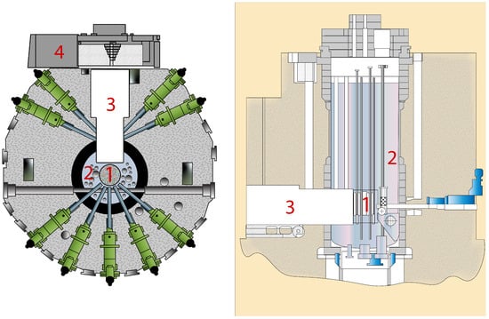
Figure 1.
Scheme of the WWR-K reactor: top view (left) and side view (right). 1—reactor core; 2—moderator; H2O; 3—thermal column; 4—rollback protection.
Neutrons enter the thermal column primarily through its front wall. The calculation performed using the MCNP6.2 program [53] shows that the maximum flux of TNs on the front wall of the thermal column is 1012 cm−2 s−1 [54]. We plan on placing the UCN source near the front wall of the thermal column, the diagram of which is shown in Figure 2.
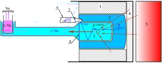
Figure 2.
Scheme of the UCN source at the WWR-K reactor. 1—trap with SF 4He at a temperature K; 2—LD2, 20 K; 3—graphite, 300 K; 4—Pb; 5—reactor active zone; 6—neutron guide; 7—separating foil; 8—heat-conducting wall.
The main element of the source is a cylindrical trap with SF 4He (1, Figure 2) at a temperature K, in which UCNs are formed from CNs and accumulated. CNs, in turn, are formed in LD2 (2, Figure 2) from TNs and fast neutrons. LD2, which is one of the best cold moderators [55], surrounds the trap’s lateral cylindrical surface (1, Figure 2) and its end face facing the reactor. The opposite end-cap is not surrounded by LD2 because it hosts the extraction channel/cryogenic hardware. LD2 has a temperature K.
Fast neutrons are produced by nuclear fission in the reactor core (5, Figure 2). The core is surrounded by beryllium and light water moderator (Be and H2O, not shown in Figure 2 for simplicity), which slows down fast neutrons to thermal energies. The water layer between the core and the front wall of the thermal column has a variable thickness with a minimum at 5 mm in the central part of this wall. The maximum of the thermal neutron flux also enters the UCN source from the central part of the front wall of the thermal column. The graphite layer surrounding the LD2 tank (3, Figure 2) serves as an additional thermal neutron moderator.
A large enough flux of -rays comes from the reactor core and the H2O surrounding it, resulting in significant radiation heating of SF 4He. To reduce this heat influx, a Pb shield (4, Figure 2) is installed close to the front wall of the thermal column, which reduces the flux of -rays hundreds of times. Although to a lesser extent, the lead shield also reduces the neutron flux, thereby reducing the productivity of the UCN source. Therefore, the thickness of the Pb shield must be optimized in such a way as to keep the total radiation heat within the capacity of the cryogenic equipment while avoiding an excessive reduction in the neutron flux. Note that a source capable of working in the UCN accumulation mode might benefit from working at a lower neutron flux with an additional -shielding if it allows the cryogenic equipment to cool to below 0.9 K operation temperatures.
The UCNs produced in the source can be reflected multiple times from the internal walls of the accumulation trap and remain there until they enter the exit located at the top of the trap (1, Figure 2), or they are lost due to heating by phonons in SF 4He or due to losses in the source trap walls. Then, they pass through a sealed separating foil (7, Figure 2) and enter the neutron guide (6, Figure 2), which leads to the experimental setups. The source walls must be coated with a material with a high critical energy and a low UCN loss coefficient to ensure multiple reflections of the UCNs from them.
The separating foil must be made of a material with a low critical energy and a small UCN loss cross-section (aluminum (Al) is generally used for this). The separating foil performs two functions: First, it reflects the black body radiation coming from the higher temperature neutron guide. Second, it separates the vacuum of the neutron guide and the source, preventing the cryopumping of contaminants by the SF 4He bulk.
The thickness of the LD2 layer on the reactor side is approximately twice larger than its thickness around the cylindrical surface of the trap (1, Figure 2). This is necessary to prevent fast neutrons from entering the SF 4He, which is another factor in the influx of heat into the source.
The design of our source (Figure 2) is similar to that of the UCN source in the PNPI project, which is not unexpected given the similarity of the designs of the reactors themselves. However, our source design has significant differences from both projects, PNPI and TRIUMF. In both of the projects, heat is removed through the free circulation of SF 4He between the UCN source and the cooling system, which is located 2–3 m from the source, behind the biological protection. SF 4He freely circulates in a wide tube, 14–15 cm in diameter. The same tube is also a neutron guide, through which UCNs are transported from the source to the experimental setups. Therefore, UCNs accumulate simultaneously in the entire source–neutron guide–experimental setup system. The UCN density is diluted proportionally to the increase in the total volume of the system. In addition, a long storage time of UCNs must be provided in each part of this system. It is most complicated to provide this in the neutron guide, which necessarily contains separating foils through which UCNs pass, repeatedly and in both directions. Typically, neutron guides also contain movable devices with significant gaps (dampers, movable shutters, etc.).
The advantage of such a design is the reduced requirements for the UCN storage time in the source, and, consequently, for the SF 4He temperature in it, as well as for the quality of the accumulation trap walls. The productivity of the UCN source of such a design may even be somewhat higher than ours, due to the allowance of a higher limit of heat inflow; however, this factor may be leveled out due to the comparably large losses of UCNs during their transport.
In our source, we plan to separate the heat and UCN transport. To this end, the heat to be removed through the heat-conducting wall (8, Figure 2) of the source, and the UCNs are extracted through a relatively small hole. Then, the UCNs are transported to the experimental setups through a special focusing neutron guide, described in more detail in Section 4.3. The UCN density at its exit can be close to that at its entrance. This method provides the possibility of UCN accumulation to a high density both in the source and in the experimental setup.
To maintain the temperature of SF 4He in the source below 1 K, it is necessary to use a cooling system based on pumping out 3He vapor, which is similar to that used in the TRIUMF project and is schematically shown in Figure 2.
The described concept of the UCN source contains novel, untested methods, such as cooling the source through a heat-conducting wall to a temperature below 1 K and the use of focusing UCN neutron guides. Thus, it is necessary to prove the feasibility of its implementation. For this purpose, preliminary studies are planned in three directions: (i) to measure the amount of heat that can be removed from SF 4He through a heat-conducting wall at a temperature of about 1 K and below, depending on the temperature; (ii) to evaluate surface coatings with high critical energy that can be used to cover the inner walls of the UCN source; and (iii) to calculate and develop focusing UCN guides.
3. Results
3.1. Estimates of the 8.9 Å Neutron Flux
Using the MCNP6 program [53], we calculated several possible UCN source geometries similar to the scheme shown in Figure 2. The calculations were of a twofold aim. First was to determine the dependence of the differential neutron flux in the source on the neutron wavelength, . Using that dependence, we calculated the flux at wavelength Å, corresponding to the neutron energy of about 1.02 meV. Using that value, we calculated the UCN source productivity neglecting multi-phonon processes, because taking them into account only slightly increase the source productivity and the UCN density. Second was to calculate the heat influx to all elements of the source. All primary configurations were simulated with high statistics (of the order of particle histories per configuration), yielding relative statistical uncertainties of approximately 3 to 5% for the key tallies.
Several shielding and moderator geometries were simulated. Here, we present results for the AlSUN geometry, which is quite close to that in the PNPI project: the volume of the cylindrical trap with SF 4He (1, Figure 2) is 35 l (with the diameter of 30 cm, and the height of 50 cm), the LD2 volume is about 90 l, the LD2 thickness on the reactor core side is 20 cm, and the thickness of the Pb is 10 cm. These values allow us to benchmark our calculations to eliminate potential errors and conservatively estimate expected UCN yield. Note that as described in Section 2.2 above, the PNPI geometry was optimized for continuous UCN extraction without any accumulation of UCN in the source, i.e., for the short lifetime of UCN in the production volume due to a relatively large diameter of UCN extraction guide. Nevertheless, it is still a relatively good first approximation to the optimal geometry for our UCN source as well. Indeed, the optimization of the accumulation mode requires quite good quantitative knowledge of the actual radiative heating. Therefore, the optimization has to be approached with a more matured engineering design and realistic materials.
Figure 3 shows the dependence of the differential neutron flux on the neutron wavelength in the trap with SF 4He, averaged over its volume.
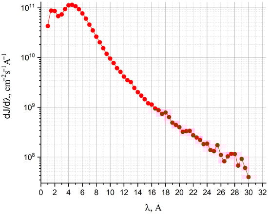
Figure 3.
Differential neutron flux averaged over the volume of the SF 4He trap.
The flux of CNs with a wavelength of 8.9 Å (≈ 1.02 meV), extracted from this dependence, is Å cm−2 s−1 Å−1.
3.2. Estimates of UCN Production
The specific rate of production of UCNs with energies lower than the beryllium (Be) critical energy (of approximately 252 neV), R, due to the one-phonon process in 1 cm3 of SF 4He can be calculated using the following formula: Å cm−3 s−1 [56]. Here, the letter R is preceded by the subscript “Be”, which indicates that the part of the UCN spectrum limited by the Be critical energy is taken into account (UCNs are produced in a trap with Be-coated walls).
When UCNs are produced, they uniformly fill the phase space, so their spectrum can be described as
where E denotes the UCN energy.
The specific rate of production of UCNs depends on the critical energy (neutron–nuclei optical potential) of the trap walls, , as follows:
where neV is the critical energy of SF 4He.
The production rate of the UCN source with a volume V (in the case under consideration, l) is
For our source, with trap walls coated with Be, s−1, which is in good enough agreement with the calculations carried out at the PNPI (Be (6–8) s−1) [46], taking into account that the power of the WWR-K reactor is about 3 times lower than the power of the PNPI reactor.
Our MCNP-based evaluation accounts for the following sources of radiation incident on or generated within the UCN source: -rays from the reactor core and light water moderator transmitted through the Pb shielding and the premoderator to the SF 4He volume, fast neutrons from the reactor core, and products of neutron capture along the path and in surrounding structures—prompt -rays together with delayed emission from neutron activation. Charged particles originating in the trap wall (Al in the baseline design), which is in direct thermal contact with the SF 4He, deposit their energy efficiently into the UCN production volume, whereas charged particles produced in Pb shields or other remote components are stopped locally and do not reach the SF 4He. When all channels are combined, the total heat load at a reactor power of 6 MW is approximately of 10 W, of which about two thirds arises from energy deposition in the Al wall of the trap; the remaining approximately one third is shared among the transmitted -ray and fast neutron components and the capture/activation products delivered to the SF 4He. This partitioning motivates replacing Al wholly or in part with Be or Zircaloy-IV, or employing an Al–Be alloy, to reduce wall losses and the overall load. For context, an analogous concept studied for the WWR-M (Gatchina, Russia) reactor yields a source heat load of approximately 19 W [46] at 16 MW thermal power for a geometry close to ours. Our neutron flux calculations reproduce these results, while our heat deposition estimate is, if anything, more conservative, supporting the internal consistency of our calculations.
Let us estimate the maximum UCN density that can be produced and accumulated in the source. To this end, let us consider a closed source (the UCN exit from the trap is closed), so that
where the storage time of UCNs in the closed sourceis determined by the following formula:
with the partial UCN storage time in SF 4He, the partial UCN storage time in the trap determined only by losses during their interaction with the walls of the trap, and s [57] the partial neutron lifetime determined by its -decay.
, as indicated in Equation (5), strongly depends on He temperature, [56]. The values of at several temperatures are listed in Table 2.
Table 2.
Partial storage time of UCNs in SF 4He and storage time of UCNs in closed source with Be walls and the loss factor at different SF 4He temperatures.
is determined using the probability of UCN losses while they are reflected from the trap walls, and the frequency of impacts on the walls is . In turn, the probability of losses is determined by the loss factor , which is the ratio of the imaginary and real parts of the neutron–nuclei optical potential of the wall material. The values of the loss factors for different materials highly vary, while the theoretical values of are in general significantly lower than the values achieved in practice. For example, the theoretical value for Be is , and the minimum value obtained in practice is [58]. For the calculations of the TRIUMF and PNPI, the value was chosen. We also choose that value to estimate the storage time of UCNs in the closed source with Be walls at the different He temperatures as given in Table 2.
If a He temperature of about 0.9 K is achieved, we obtain UCN/cm3.
3.3. Extraction and Transport of UCNs
Let the UCN source have an exit hole of area , leading to a neutron guide from which neutrons do not return. Then, the storage time in the source is determined as
The exit time is , where exit frequency is , and is the area of the source walls. In our case, cm2. Let be such that s; then, cm2 at an UCN velocity of 5 m/s. In this case, the rate of UCNs exiting the source and entering the neutron guide is .
If an expanding mirror cone is installed at the beginning of a mirror neutron guide, the motion of UCNs becomes rather directed along the axis of the neutron guide. The frequency of impacts on the walls of the neutron guide, and, consequently, the losses of UCNs in it, to be sharply reduced. Moreover, the larger the ratio of the neutron guide diameter to the size of the source exit opening, the less often the UCNs hit the walls. At the end of the neutron guide, before the entrance to the experimental setup, a tapering cone can be placed, focusing the UCNs onto an area equal to . This is the same principle that is used in the design of so-called ballistic neutron guides for CNs and TNs [59,60], which have significantly higher transmission compared to parallel neutron guides and provide a significantly higher neutron flux at the exit.
For UCNs, similar neutron guides have not yet been designed. Apparently, this is because UCN sources based on SF 4He have only recently come into use, and only these neutron guides are able to provide a significant portion of UCNs through a comparably small hole, since in other sources, UCN survive thousands of times less. Some calculation results of such neutron guides are presented in Section 4.3; detailed calculations are considered to be presented elsewhere. Let us estimate the density of UCNs in the experimental setup. Let us assume that during the transportation of UCNs along the neutron guide in one pass, half to be lost (calculations show that this is plausible in the neutron guide described below in Section 4.3 with a length of about 5 m, even if it has separating foils and moving devices). Let us also assume that the experimental setup has the same volume as the source and the same storage time as the source. In this case, . Indeed, factor 2 is being in the source, another factor 2 is being lost in the neutron guide, and one more factor 2 is being lost in the experimental setup. If is excluded from , since the experimental setup is not filled with SF 4He, then
In this assessment, it is not taken into account that the UCNs are affected by gravity and that the UCNs has to overcome the separating foil before entering the neutron guide. Let us estimate the corresponding corrections.
First, the exit of the source is located at a height of about 30 cm from the bottom of the source. Not all UCNs produced in the source have sufficient energy to reach it, and the others have energy reduced by a value corresponding to this height. Actually, this leads to a cutoff of the UCN spectrum on the side of high energies. The calculation for the UCN spectrum (1) in a source with Be walls gives the correction factor to the rate of UCNs exiting.
Second, with an isotropic distribution of the direction of UCN motion in the source, the flux of UCNs with energy E at the bottom of the source decreases linearly with an increasing height. This leads to a decrease in the exit rate from the source. The corresponding correction factor is .
Third, if a mm thick separating Al foil is placed behind the diverging mirror cone in the neutron guide, then UCNs falls on the foil at an angle close to the normal. In that case, the probability of a UCN passing through the foil is for a spectrum (1) in a source with Be walls.
Then, the combined correction is
The UCN density in the experimental setup is proportional to the exit rate if the size of the exit hole from the source and the entrance hole into the experimental setup are not changed:
When choosing the area of the exit hole from the source, we do not optimize the area in order to obtain the maximum value of the flux, so a higher value can be obtained if necessary (compromising the UCN rate). Let us also note that the estimated value of the UCN density in the experimental setup decreases by 25% if the SF 4He temperature in the source is changed from 0.9 K to about 1 K.
Thus, calculations show that if the proposed consideration is feasible, the rate of UCN production can be as high as 2.6 × 10⁷ UCN/s, resulting in the maximum UCN density and in the experimental setup 6 × 10⁴ UCN/cm3 and 5 × 10³ UCN/cm3, correspondently.
4. Discussion
4.1. Investigation of the Cooling System with a Heat-Conducting Wall
At low temperatures, heat exchange between SF 4He and a solid is due to the exchange of energy between phonons at the interface between these media. Due to the large difference in the phonon spectra of the solid and SF 4He, this exchange is strongly suppressed; phonons of the hotter body are almost fully reflected from the interface. As a result of this effect, a finite temperature difference arises between the solid and SF 4He—the Kapitsa temperature jump [61], , which is the main obstacle to cooling bodies to ultra-low temperatures. The jump is directly proportional to the heat flux Q and inversely proportional to : , where is the Kapitsa resistance. The coefficient A depends on the elasticity of the solid, as well as on the surface roughness and defects of the surface layer, oxides, layers of adsorbed gas, etc.
The temperature difference between SF 4He, , located on different sides of the heat-conducting wall consists of two Kapitsa temperature jumps at the 4He-wall, wall-4He boundaries, and the temperature difference across the wall material. For a given heat flux through a specific wall, is measured experimentally.
The existence of the Kapitza temperature jump leads to an increase in the SF 4He temperature in the UCN production volume, which contradicts the need to reduce its temperature. To achieve the required result, it is needed to increase the efficiency of the 3He-4He heat exchanger in order to reduce the temperature of 4He in front of the heat-conducting wall of the source. This can be achieved by increasing the effective area of the heat exchanger. In addition, it is necessary to increase the area of the heat-conducting wall in order to reduce the heat flux through the wall. We plan to remove heat through the rear wall of the source with a diameter of 30 cm. With a heat load of 10 W, the heat flux through it is expected to be 140 W/m2.With this value of the heat flux, does not exceed 0.2 K at a temperature of 1 K. If the area is not sufficient, it is possible to enlarge the heat conducting wall surface on the side opposite to the UCN production volume.
We plan to measure the dependence of on the heat flux through the heat-conducting wall at a temperature of about 1 K. The measurement is planned to be carried out in a comparably small cryostat with 3He vapor pumping, providing a temperature after the heat exchanger of 4He of about 0.7 K, with a heat inflow of about 0.1 W.
4.2. Investigation of Wall Coatings with High Critical Energy
Here, we consider the UCN exit rate from the source as a function of the critical energy of the source trap walls.
Figure 4 shows the ratio of the UCN exit rate from the source, , for different critical energies of the source walls, to the UCN exit rate from the source with Be walls, . This ratio is presented for natural copper (Cu), stainless steel (St. st.), natural nickel–phosphorus coating (Ni-P, with phosphorus content of 10%), natural nickel, natural Be, 58Ni-P coating (phosphorus content of 10%), diamond, and 58Ni. For all these coatings, the loss factor was assumed to be .
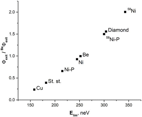
Figure 4.
Exit rates of UCNs from the source for different coatings of its walls, depending on the critical energy of the coating, in relation to the exit rate from the source with Be walls. See text for details.
From Figure 4, one immediately sees that the dependence of on the value of the critical energy of the walls is coniderably stronger than . Doubling the critical energy increases the exit rate by a factor of 7.5 (Figure 4) rather than a factor of 2.8 as to be expected from the dependence . This indicates that when manufacturing the source, special attention need to be paid to materials with high critical energy.
We plan to carry out a comprehensive study of the coatings with largest critical energies to select a coating stable in high-radiation fields at cryogenic temperatures and with a minimal UCN loss probability. In particular, we plan to measure the probability of UCN loss, , during their interaction with the surfaces of the studied materials, depending on the UCN energy, in the entire energy range from 0 to . For this purpose, we plan to irradiate the studied samples with a narrow UCN energy line, with a width of about 5–10 neV. Such measurements for high critical energies in the range of about 300 neV have never been taken. The experiment is planned to be performed at the PF2 UCN beamline of the ILL, Grenoble, France.
4.3. Some Calculation Results of Focusing Neutron Guides of UCNs
Here, we compare the transmission coefficients and flux of UCNs at the exit from direct and focusing neutron guides based on numerical simulation using the PENTrack package [62].
Figure 5 shows two geometries of UCN neutron guides. The straight neutron guide has the shape of a cylinder with a diameter of 8 cm and a length of 5 m. The focusing neutron guide consists of an expanding cone, a straight cylindrical neutron guide, and a tapering cone. Each of the two truncated cones has a small diameter of 2 cm, a large diameter of 8 cm, and a length of 30 cm. The diameter of the cylindrical part is 8 cm. The focusing guide total length is 5 m, the same as that of the straight cylindrical neutron guide.
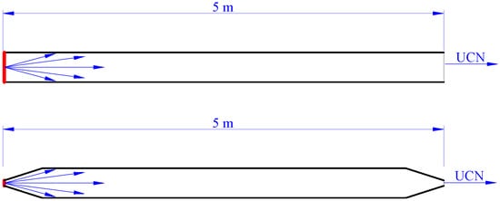
Figure 5.
The direct (upper) and the focusing (lower) neutron guides used for calculations. UCN sources with a Lambert angular distribution are shown in red.
Through one end of the neutron guides, marked in red in Figure 5, the same UCN rate enters the neutron guides. The UCNs have the Lambert angular distribution , where is the solid angle, and is the angle between the direction of UCN motion and the normal to the source surface. It corresponds to the isotropic UCN source.
The calculation ignores the UCN losses during their reflection from the guide walls and assumes totally specular reflection. In this case, all UCNs reach the exit of the direct neutron guide. For the focusing neutron guide, 20% of UCNs are reflected back from the tapering exit part. We assume that all such UCNs are lost. Then, the transmission coefficient of the direct neutron guide and the focusing guide . The mean number of UCN impacts on the walls of the direct neutron guide is , and in the focusing guide.
Figure 6 shows the transmission coefficients of neutron guides depending on the probability of UCN losses, , when hitting the wall (Figure 6a) and the ratio of UCN flux at the exit of the neutron guides (Figure 6b). As can be seen, the flux at the exit from the focusing guide can be ten times higher than the flux at the exit from the direct neutron guide. Here, the value of includes and is dominated by the probability of off-specular reflection of UCNs from the surfaces of neutron guides. Note that specular reflection of UCNs at any angle of incidence on the surface can be achieved for both well-polished surfaces [63] and coatings [64]. In this case, the value of can be as low that the corresponding additional losses might be only a few percent. Note that the only condition for the partial coefficient of UCN losses due to capture and inelastic scattering is that it is noticeably smaller than the probability of off-specular reflection. This can be certainly provided even for rectangular neutron guides.
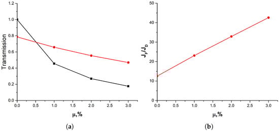
Figure 6.
(a): the transmission coefficients of neutron guides depending on the probability of UCN loss, , upon impact with the neutron guide wall. The black line represents the transmission of the direct neutron guide and the red line, the transmission of the focusing neutron guide. (b): the ratio of the UCN flux at the exit from the neutron guides. and denote the flux at the exit from the focusing and direct neutron guide, respectively.
The UCN flux at the exit of a neutron guide is determined by the ratio of the guide transmission to the area of its exit aperture. It may seem that the smaller the exit diameter, the higher the UCN flux. However, this is not the case. The maximum flux achievable in focusing UCN guides depends on the angular distribution of UCNs at the entrance. For a Lambert distribution at the entrance, the maximum UCN flux at the exit is reached when the exit diameter equals the entrance diameter. If the exit aperture is reduced further, the UCN flux at the exit does not change, but a larger number of UCNs are reflected back, i.e., the guide transmission decreases. An even higher gain in both the transmission of the guides and the UCN flux at the exit can be obtained if cones are replaced with paraboloids. More details of focusing UCN guides features to be presented elsewhere.
Increasing the UCN flux at the guide exit by tapering the guide can significantly increase the UCN density in a trap installed at the end of the guide. The maximum increase is for small traps, with volumes of about 100 l and less, whose walls are made of a material with quite a low loss factor. In such traps, UCN losses due to outflow through the open entrance window exceeds other losses and the accumulated UCN density is proportional to the UCN flux at the trap entrance. For large UCN traps, with volumes of several cubic meters, installing a tapered section of the guide is unreasonable. However, even in this case, one can expect a noticeable gain due to the increased transmission in the guides considered.
5. Conclusions
In this paper, we presented the concept of a UCN source at the WWR-K reactor of the Institute of Nuclear Physics (Almaty, Kazakhstan). Broad international collaboration has led us to expect record values for this source, given the convenient design features of this reactor (the presence of a thermal column, the sufficiently high neutron flux, and sufficient space to accommodate the source equipment and experimental setups), the existence of well-developed UCN projects of this type (Vancouver, Canada, and Gatchina, Russia), and novel methods and materials. However, some of these methods (the accumulation and transport of UCNs), as well as the need to cool SF 4He to low temperatures under significant thermal load require additional research. This paper can be considered the first paper describing this project, showing both its potential and issues requiring additional research.
Author Contributions
Conceptualization, S.S., K.T., E.K., E.L., A.M. and V.N.; methodology, K.T., E.K., A.M. and V.N.; software, A.S. (Asset Shaimerdenov), D.S., C.T. and K.T.P.; validation, E.K., E.L., A.M. and V.N.; formal analysis, K.T., E.K., A.M. and V.N.; investigation, S.S., K.T., A.S. (Asset Shaimerdenov), D.S., A.S. (Avganbek Sabidolda), Z.K., A.A., O.B., R.K., E.K., E.L., A.M., V.N., C.T. and K.T.P.; data curation, K.T., E.K., E.L., A.M. and V.N.; writing—original draft preparation, K.T., E.K., A.M. and V.N.; writing—review and editing, S.S., K.T., A.A., E.K., E.L., A.M. and V.N.; visualization, K.T., E.K., A.M. and V.N.; supervision, S.S. and V.N.; project administration, S.S. and K.T.; funding acquisition, S.S. and K.T. All authors have read and agreed to the published version of the manuscript.
Funding
The work was carried out with the financial support of the Science Committee of the Ministry of Science and Higher Education of the Republic of Kazakhstan within the framework of grant funding for young scientists for scientific and scientific–technical projects No. AP19579042.
Data Availability Statement
The original contributions presented in this study are included in the article; further inquiries can be directed to the corresponding author.
Acknowledgments
The idea of designing the UCN source in Almaty, Kazakhstan (AlSUN), was presented and discussed during the dedicated workshop on UCN and VCN Source at the Institute of Nuclear Physics, 8–11 April 2024, INP, Almaty, Kazakhstan [65]. The workshop participants discussed a much wider range of issues related to the concept of the source, the methods for its implementation, and the scientific program using this source. To avoid repetition, we do not reproduce these results here and refer the reader to the materials of this workshop.
Conflicts of Interest
The authors declare no conflicts of interest.
Abbreviations
The following abbreviations are used in this manuscript:
| AISUN | Almaty Source of Ultracold Neutrinos |
| BSET | Bulk Shielding Experimental Tank |
| CN | cold neutron |
| ILL | Institut Laue–Langevin |
| JINR | Joint Institute for Nuclear Research |
| INP | Institute of Nuclear Physics |
| LD2 | liquid deuterium |
| MCNP | Monte Carlo N-Particle |
| P | phosphorus |
| PENtrack | simulation tool for PENeLOPE (Precision Experiment on the Neutron Lifetime Operating with Proton Extraction) |
| PF2 | ultracold neutron facility at ILL |
| PNPI | Petersburg Nuclear Physics Institute |
| SF | superfluid |
| St. st. | stainless steel |
| SuperSUN | Super Ultracold Neutron Source |
| TRIGA | Training, Research, Isotopes, General Atomic |
| TRIUMF | TRI University Meson Facility |
| TN | thermal neutron |
| WWR-K | Water–Water Reactor—Kazakhstan |
| WWR-M | Water–Water Reactor—Modernized |
| UCN | ultracold neutron |
References
- Lushchikov, V.I.; Pokotilovskii, Y.N.; Strelkov, A.V.; Shapiro, F.L. Observation of ultracold neutrons. Pis’ma ZhETF 1969, 9, 40–45. (In Russian); English translation: Sov. Phys. JETP Lett. 1969, 9, 23–26. Available online: http://jetpletters.ru/ps/1639/article_25024.shtml (accessed on 19 September 2025).
- Steyerl, A. Measurements of total cross sections for very slow neutrons with velocities from 100 m/sec to 5 m/sec. Phys. Lett. B 1969, 29, 33–35. [Google Scholar] [CrossRef]
- Akhmetov, E.Z.; Kaipov, D.K.; Konks, V.A.; Lushchikov, V.I.; Pokotilovskii, Y.N.; Strelkov, A.V.; Shapiro, F.L. Production of ultracold neutrons in a stationary (steady-state) reactor of the VVR-K (water-cooled, water-moderated) type. Atom. Ener. 1974, 37, 35–38. (In Russian); English translation: Sov. At. Energy 1974, 37, 712–715. [Google Scholar] [CrossRef]
- Akhmetov, E.Z.; Kaipov, D.K.; Konks, V.A.; Kulagin, E.N.; Machnev, N.F.; Strelkov, A.V.; Tretyakov, L.I. Installation for generating and transmission measurements of ultracold neutrons at the radial channel of the VVR-K reactor. In Neutron Physics. Part 1; Usachev, L.N., Vertebny, V.P., Kardashev, D.A., Manokhin, V.N., Eds.; TsNIIAtominform: Moscow, USSR; pp. 178–181. Available online: https://www-nds.iaea.org/publications/indc/indc-ccp-0118-3/ (accessed on 19 September 2025). (In Russian)
- Ignatovich, V.K. The Physics of Ultracold Neutrons; Clarendon Press/Oxford University Press: Oxford, UK, 1990. [Google Scholar] [CrossRef]
- Golub, R.; Richardson, D.; Lamoreaux, S. Ultra-Cold Neutrons; CRC Press, Taylor & Francis Group: Boca Raton, FL, USA, 1991. [Google Scholar] [CrossRef]
- Tutunnikov, I.; Voronin, A.Y.; Nesvizhevsky, V.V.; Averbukh, I.S. Impulsively excited gravitational quantum states: Echoes and time-resolved spectroscopy. Phys. Rev. Lett. 2021, 126, 170403. [Google Scholar] [CrossRef]
- Lawson, L.; Gouba, L.; Avossevou, G.Y. Two-dimensional noncommutative gravitational quantum well. J. Phys. A Math. Theor. 2017, 50, 475202. [Google Scholar] [CrossRef]
- Lamoreaux, S.K.; Golub, R. Experimental searches for the neutron electric dipole moment. J. Phys. G 2009, 36, 104002. [Google Scholar] [CrossRef]
- Chupp, T.E.; Fierlinger, P.; Ramsey-Musolf, M.J.; Singh, J.T. Electric dipole moments of atoms, molecules, nuclei, and particles. Rev. Mod. Phys. 2019, 91, 015001. [Google Scholar] [CrossRef]
- Brown, M.A.-P. et al. [UCNA Collaboration] New result for the neutron β-asymmetry parameter A0 from UCNA. Phys. Rev. C 2018, 97, 035505. [Google Scholar] [CrossRef]
- Sun, X. et al. [UCNA Collaboration] Improved limits on Fierz interference using asymmetry data. Phys. Rev. C 2020, 101, 035503. [Google Scholar] [CrossRef]
- Nesvizhevsky, V.V.; Voronin, A.Y.; Cubitt, R.; Protasov, K.V. Neutron whispering gallery. Nat. Phys. 2010, 6, 114–117. [Google Scholar] [CrossRef]
- Jenke, T. Gravity resonance spectroscopy and dark energy symmetron fields. Eur. Phys. J. Spec. Top. 2021, 230, 1131–1136. [Google Scholar] [CrossRef]
- Ayres, N.J.; Bison, G.; Bodek, K.; Bondar, V.; Bouillaud, T.; Chanel, E.; Chiu, P.-J.; Clement, B.; Crawford, C.B.; Daum, M.; et al. Search for an interaction mediated by axion-like particles with ultracold neutrons at the PSI. New J. Phys. 2023, 25, 123001. [Google Scholar] [CrossRef]
- Dubbers, D.; Märkisch, B. Precise measurements of the decay of free neutrons. Annu. Rev. Nucl. Part. Sci. 2021, 71, 139–163. [Google Scholar] [CrossRef]
- Wietfeldt, F.E. The Neutron lifetime discrepancy and its implications for cosmology and dark matter. Symmetry 2024, 16, 956. [Google Scholar] [CrossRef]
- Pedram, P. Exact ultra cold neutrons’ energy spectrum in gravitational quantum mechanics. Eur. Phys. J. C 2013, 73, 2609. [Google Scholar] [CrossRef]
- Dehghani, P.; Nozari, K. IR-deformed thermodynamics of quantum bouncers and the issue of dimensional reduction. arXiv 2020, arXiv:2002.10279. [Google Scholar] [CrossRef]
- Engel, J.; Ramsey-Musolf, M.J.; van Kolck, U. Electric dipole moments of nucleons, nuclei, and atoms: The Standard Model and beyond. Prog. Part. Nucl. Phys. 2013, 71, 21–74. [Google Scholar] [CrossRef]
- Jenke, T.; Geltenbort, P.; Lemmel, H.; Abele, H. Gravity resonance spectroscopy constrains dark energy and dark matter scenarios. Phys. Rev. Lett. 2014, 112, 151105. [Google Scholar] [CrossRef] [PubMed]
- Siemensen, C.; Brose, D.; Böhmer, L.; Geltenbort, P.; Plonka-Spehr, C. Search for an electric charge of the neutron. Phys. Rev. D 2018, 97, 052004. [Google Scholar] [CrossRef]
- Fomin, N.; Fry, J.; Pattie, R.W., Jr.; Greene, G.L. Fundamental neutron physics at spallation sources. Annu. Rev. Nucl. Part. Sci. 2022, 72, 151–176. [Google Scholar] [CrossRef]
- Abel, C.; Afach, S.; Ayres, N.J.; Baker, C.A.; Ban, G.; Bison, G.; Bodek, K.; Bondar, V.; Burghoff, M.; Chanel, E.; et al. Measurement of the permanent electric dipole moment of the neutron. Phys. Rev. Lett. 2020, 124, 081803. [Google Scholar] [CrossRef]
- Ayres, N.J. et al. [nEDM Collaboration] The design of the n2EDM experiment. Eur. Phys. J. C 2021, 81, 512. [Google Scholar] [CrossRef]
- Gonzalez, F.M. et al. [UCNτ Collaboration] Improved neutron lifetime measurement with UCNτ. Phys. Rev. Lett. 2021, 127, 162501. [Google Scholar] [CrossRef]
- Guerrero, O.; Barrón-Palos, L.; Sudarsky, D. On the electric dipole moment of the neutron and its quantum uncertainty. Ann. Phys. 2024, 469, 169761. [Google Scholar] [CrossRef]
- Koch, B.; Muñoz, E.; Santoni, A. Ultracold neutrons in the low-curvature limit. Phys. Rev. D 2024, 109, 064085. [Google Scholar] [CrossRef]
- Ban, G.; Chen, J.; Lefort, T.; Naviliat-Cuncic, O.; Saenz-Arevalo, W.; Chiu, P.J.; Clément, B.; Larue, P.; Pignol, G.; Roccia, S.; et al. Search for neutron-to-hidden-neutron oscillations in an ultracold neutron beam. Phys. Rev. Lett. 2023, 131, 191801. [Google Scholar] [CrossRef]
- Broussard, L.J.; Barrow, J.L.; DeBeer-Schmitt, L.; Dennis, T.; Fitzsimmons, M.R.; Frost, M.J.; Gilbert, C.E.; Gonzalez, F.M.; Heilbronn, L.; Iverson, E.B.; et al. Experimental search for neutron to mirror neutron oscillations as an explanation of the neutron lifetime anomaly. Phys. Rev. Lett. 2022, 128, 212503. [Google Scholar] [CrossRef] [PubMed]
- Antoniadis, I.; Baessler, S.; Büchner, M.; Fedorov, V.V.; Hoedl, S.; Lambrecht, A.; Nesvizhevsky, V.V.; Pignol, G.; Protasov, K.V.; Reynaud, S.; et al. Short-range fundamental forces. Comptes Rendus. Phys. 2011, 12, 755–778. [Google Scholar] [CrossRef]
- Nesvizhevsky, V.V.; Börner, H.G.; Petukhov, A.K.; Abele, H.; Baeßler, S.; Rueß, F.J.; Stöferle, T.; Westphal, A.; Gagarski, A.M.; Petrov, G.A.; et al. Quantum states of neutrons in the Earth’s gravitational field. Nature 2002, 415, 297–299. [Google Scholar] [CrossRef] [PubMed]
- Degenkolb, S.; Chanel, E.; Baudoin, S.; Baur, M.H.; Beck, D.H.; Blé, J.; Bourgeat-Lami, E.; Castillo, Z.; Filter, H.; van der Grinten, M.; et al. High-density ultracold neutron source for low-energy particle physics experiments. arXiv 2025, arXiv:2504.13030. [Google Scholar] [CrossRef]
- Golub, R.; Pendlebury, J.M. Super-thermal sources of ultra-cold neutrons. Phys. Lett. A 1975, 53, 133–135. [Google Scholar] [CrossRef]
- Golub, R.; Jewell, C.; Ageron, P.; Mampe, W.; Heckel, B.; Kilvington, I. Operation of a superthermal ultra-cold neutron source and the storage of ultra-cold neutrons in superfluid Helium4. Z. Phys. B 1983, 51, 187–193. [Google Scholar] [CrossRef]
- Yoshiki, H.; Sakai, K.; Ogura, M.; Kawai, T.; Masuda, Y.; Nakajima, T.; Takayama, T.; Tanaka, S.; Yamaguchi, A. Observation of ultracold-neutron production by 9-Å cold neutrons in superfluid helium. Phys. Rev. Lett. 1992, 68, 1323–1326. [Google Scholar] [CrossRef] [PubMed]
- Golub, R. Ultracold neutrons (UCN) at a TRIGA reactor. Nucl. Instrum. Meth. Phys. Res. A Accel. Spectrom. Detect. Assoc. Equip. 1984, 226, 558–559. [Google Scholar] [CrossRef]
- Masuda, Y. Ultra-cold neutron production with superfluid helium and spallation neutrons. Nucl. Instrum. Methods Phys. Res. Sect. A Accel. Spectrom. Detect. Assoc. Equip. 2000, 440, 682–684. [Google Scholar] [CrossRef]
- Masuda, Y.; Kitagaki, T.; Hatanaka, K.; Higuchi, M.; Ishimoto, S.; Kiyanagi, Y.; Morimoto, K.; Muto, S.; Yoshimura, M. Spallation ultracold-neutron production in superfluid helium. Phys. Rev. Lett. 2002, 89, 284801. [Google Scholar] [CrossRef] [PubMed]
- Masuda, Y.; Hatanaka, K.; Jeong, S.; Kawasaki, S.; Matsumiya, R.; Matsuta, K.; Mihara, M.; Watanabe, Y. Spallation ultracold neutron source of superfluid helium below 1 K. Phys. Rev. Lett. 2012, 108, 134801. [Google Scholar] [CrossRef]
- Ahmed, S. et al. [TUCAN Collaboration] First ultracold neutrons at TRIUMF. Phys. Rev. C 2019, 99, 025503. [Google Scholar] [CrossRef]
- Schreyer, W.; Davis, C.A.; Kawasaki, S.; Kikawa, T.; Marshall, C.; Mishima, K.; Okamura, T.; Picker, R. Optimizing neutron moderators for a spallation-driven ultracold-neutron source at TRIUMF. Nucl. Instrum. Meth. A Accel. Spectrom. Detect. Assoc. Equip. 2020, 959, 163525. [Google Scholar] [CrossRef]
- Sidhu, S.; Schreyer, W.; Vanbergen, S.; Kawasaki, S.; Matsumiya, R.; Okamura, T.; Picker, R. Estimated performance of the TRIUMF ultracold neutron source and electric dipole moment apparatus. EPJ Web Conf. 2023, 282, 01015. [Google Scholar] [CrossRef]
- Serebrov, A.P.; Fomin, A.K. Calculation of the ultracold neutron yield from a superfluid helium source in the WWR-M reactor. Tech. Phys. 2015, 60, 1238–1242. [Google Scholar] [CrossRef]
- Serebrov, A.P.; Fomin, A.K.; Kharitonov, A.G.; Lyamkin, V.A.; Prudnikov, D.V.; Ivanov, S.A.; Erykalov, A.N.; Onegin, M.S.; Gridnev, K.A. High-density ultracold neutron sources for the WWR-M and PIK Reactors. Crystallogr. Rep. 2016, 61, 144–148. [Google Scholar] [CrossRef]
- Onegin, M.S.; Serebrov, A.P.; Fomin, A.K.; Lyamkin, V.A. Estimation of the ultracold neutron production by a source designed for the WWR-M reactor. Tech. Phys. 2017, 62, 633–637. [Google Scholar] [CrossRef]
- Leung, K.K.H.; Muhrer, G.; Hügle, T.; Ito, T.M.; Lutz, E.M.; Makela, M.; Morris, C.L.; Pattie, R.W., Jr.; Saunders, A.; Young, A.R. A next-generation inverse-geometry spallation-driven ultracold neutron source. J. Appl. Phys. 2019, 126, 224901. [Google Scholar] [CrossRef]
- Shin, Y.C.; Snow, W.M.; Baxter, D.V.; Liu, C.-Y.; Kim, D.; Kim, Y.; Semertzidis, Y.K. Compact ultracold neutron source concept for low-energy accelerator-driven neutron sources. Eur. Phys. J. Plus 2021, 136, 882. [Google Scholar] [CrossRef]
- Piegsa, F.M.; Fertl, M.; Ivanov, S.N.; Kreuz, M.; Leung, K.K.H.; Schmidt-Wellenburg, P.; Soldner, T.; Zimmer, O. New source for ultracold neutrons at the Institut Laue–Langevin. Phys. Rev. C 2014, 90, 015501. [Google Scholar] [CrossRef]
- Chanel, E.; Baudoin, S.; Baurand, M.; Belkhier, N.; Bourgeat-Lami, E.; Degenkolb, S.; van der Grinten, M.; Jentschel, M.; Joyet, V.; Kreuz, M.; et al. Concept and strategy of SuperSUN: A new ultracold neutron converter. J. Neutron Res. 2022, 24, 111–121. [Google Scholar] [CrossRef]
- Lychagin, E.V.; Mityukhlyaev, V.A.; Muzychka, A.Y.; Nekhaev, G.V.; Nesvizhevsky, V.V.; Onegin, M.S.; Sharapov, E.I.; Strelkov, A.V. UCN sources at external beams of thermal neutrons. An example of PIK reactor. Nucl. Instrum. Meth. Phys. Res. A Accel. Spectrom. Detect. Assoc. Equip. 2016, 823, 47–55. [Google Scholar] [CrossRef]
- Shaimerdenov, A.A.; Nakipov, D.A.; Arinkin, F.M.; Gizatulin, S.K.; Chakrov, P.V.; Kenzhin, Y.A. The 50th anniversary of the WWR-K research reactor. Phys. At. Nucl. 2018, 81, 1408–1411. [Google Scholar] [CrossRef]
- Goorley, J.T.; James, M.R.; Booth, T.E.; Brown, F.B.; Bull, J.S.; Cox, L.J.; Durkee, J.W., Jr.; Elson, J.S.; Fensin, M.L.; Foster, E.A., III; et al. Initial MCNP6 Release Overview—MCNP6 Version 1.0. Technical Report LA-UR-13-22934; Los Alamos National Laboratory: Los Alamos, NM, USA, 2013. Available online: https://mcnp-green.lanl.gov/pdf_files/TechReport_2013_LANL_LA-UR-13-22934Rev.1_GoorleyJamesEtAl.pdf (accessed on 19 September 2025).
- Turlybekuly, K.; Shaimerdenov, A.A.; Sairanbayev, D.S.; Shapiro, D.; Mukhametuly, B.; Bayakhmetov, O.; Sakhiyev, S.K. Calculation of neutron and gamma fields in the niche of the thermal column of the WWR-K research reactor, considered as the location of the ultracold neutron source. NNC RK Bull. 2024, 3, 49–55. (In Russian) [Google Scholar] [CrossRef]
- Ageron, P. Cold neutron sources at ILL. Nucl. Instrum. Meth. Phys. Res. A Accel. Spectrom. Detect. Assoc. Equip. 1989, 284, 197–199. [Google Scholar] [CrossRef]
- Korobkina, E.; Golub, R.; Wehring, B.W.; Young, A.R. Production of UCN by downscattering in superfluid He. Phys. Lett. A 2002, 301, 462–469. [Google Scholar] [CrossRef]
- Navas, S. et al. [Particle Data Group Collaboration] Review of Particle Physics. Phys. Rev. D 2024, 110, 030001. [Google Scholar] [CrossRef]
- Alfimenkov, V.P.; Strelkov, A.V.; Shvetsov, V.N.; Nesvizheskiĭ, V.V.; Serebrov, A.P.; Tal’daev, R.R.; Kharitonov, A.G. Anomalous interaction of ultracold neutrons with the surface of a beryllium trap. Pis’ma ZhETF 1992, 55, 92–94. (In Russian); English translation: JETP Lett. 1992, 55, 84–87. Available online: http://jetpletters.ru/ps/1269/article_19193.shtml (accessed on 19 September 2025).
- Mezei, F. The Raison d’être of long pulse spallation sources. J. Neutron Res. 1997, 6, 3–32. [Google Scholar] [CrossRef]
- Abele, H.; Dubbers, D.; Häse, H.; Klein, M.; Knöpler, A.; Kreuz, M.; Lauer, T.; Märkisch, B.; Mund, D.; Nesvizhevsky, V.; et al. Characterization of a ballistic supermirror neutron guide. Nucl. Instrum. Meth. Phys. Res. A Accel. Spectrom. Detect. Assoc. Equip. 2006, 562, 407–417. [Google Scholar] [CrossRef]
- Kapitza, P.L. The tudy of heat transfer mechanism in helium II. Zh. Eksp. Teor. Fiz. 1941, 11, 1. (In Russian); English translation: J. Phys. USSR 1941, 4, 181–210. Reprinted in Collected Papers of P.L. Kapitza. Volume 2: 1938–1964; Ter Haar, D., Ed.; Pergamon Press Ltd.: Oxford, UK, 1965; pp. 581–624. Available online: https://archive.org/details/collected-papers-of-p.-l.-kapitza-volume-2/page/581/ (accessed on 19 September 2025).
- Schreyer, W.; Kikawa, T.; Losekamm, M.J.; Paul, S.; Picker, R. PENTrack—A simulation tool for ultracold neutrons, protons, and electrons. Nucl. Instrum. Meth. Phys. Res. A Accel. Spectrom. Detect. Assoc. Equip. 2017, 858, 123–129. [Google Scholar] [CrossRef]
- Nesvizhevsky, V.V. Polished sapphire for ultracold-neutron guides. Nucl. Instrum. Meth. Phys. Res. A Accel. Spectrom. Detect. Assoc. Equip. 2006, 557, 576–579. [Google Scholar] [CrossRef]
- Nesvizhevsky, V.V.; Pignol, G.; Protasov, K.V.; Quemener, G.; Forest, D.; Ganau, P.; Mackowski, J.M.; Michel, C.; Montorio, J.L.; Morgado, N.; et al. Comparison of specularly reflecting mirrors for GRANIT. Nucl. Instrum. Meth. Phys. Res. A Accel. Spectrom. Detect. Assoc. Equip. 2007, 578, 435–438. [Google Scholar] [CrossRef]
- International Workshop UCN and VCN Source at the Institute of Nuclear Physics, Kazakhstan, and Their Applications, 8–11 April 2024, Almaty, Republic of Kazakhstan. Available online: https://indico.inp.kz/event/3/ (accessed on 19 September 2025).
Disclaimer/Publisher’s Note: The statements, opinions and data contained in all publications are solely those of the individual author(s) and contributor(s) and not of MDPI and/or the editor(s). MDPI and/or the editor(s) disclaim responsibility for any injury to people or property resulting from any ideas, methods, instructions or products referred to in the content. |
© 2025 by the authors. Licensee MDPI, Basel, Switzerland. This article is an open access article distributed under the terms and conditions of the Creative Commons Attribution (CC BY) license (https://creativecommons.org/licenses/by/4.0/).