Abstract
The key elements in the operation of modern underwater robotic systems are hydroacoustic communication and navigation systems. Hydroacoustic data transmission channels are designed in such a way that the transmitted information signals must be resistant to various types of interference and distortion, even without preliminary estimates of the channel parameters, due to their significant non-stationarity because of the roughness of the sea surface, currents, and the movement of underwater vehicles. Furthermore, due to the high mobility of underwater vehicles, the transmission time of navigation signals and necessary information packets must be significantly reduced, which can negatively affect the noise immunity of the packages. For these purposes, digital wideband signals and orthogonal frequency division multiplexing (OFDM) are widely used; however, a number of significant drawbacks of these types of modulations often do not allow for the forming of a reliable channel for transmitting information, and for the navigation of mobile underwater systems. Unfortunately, this problem is not comprehensively presented in the literature. The authors propose to use the algorithm of digital data transmission based on the OFDM constant envelope multifrequency modulation (CE-OFDM) with differential symbol coding, which is suitable for non-stationary hydroacoustic environments. The presented algorithm, due to the minimization of the signal peak factor, can improve the signal-to-noise ratio at the receiving end by 5–10 dB, with a number of other advantages, over the classical OFDM method. The authors also numerically found groups of short binary sequences from 14–55 elements long, with the best autocorrelation properties for the formation of synchronization and navigation preambles with high noise immunity to Doppler and multipath effects that are characteristic of the hydroacoustic communication channel. The proposed algorithms were tested on the certain channel models on the Watermark acoustic simulator, as well as in shallow water at distances up to 2 km.
1. Introduction
Underwater acoustic channels are considered to be among the most difficult channels currently used in the wireless transmission of digital information. Long-range hydroacoustic signal propagation is qualitatively at lower frequencies, due to which the bandwidth of such a communication channel is considerably limited. Low speed of sound propagation in water is one of the factors of significant time delays in data transmission. The difference in the arrival of signals at the receiving point (tens to hundreds of milliseconds at distances up to 10 km) leads to frequency-selective fading [1,2]. The characteristic physical properties of underwater communication channels are related to the fact that a sound beam falling on the interface between two media with different sound speeds is partially reflected from the interface, and partially refracted, penetrating into the second medium. Interfaces can be between water and air, water and the bottom, and between water layers with different densities; if the difference in sound speed is large, then almost a complete reflection of sound occurs. Thus, approximately one-thousandth of the incident sound energy passes through the water–air interface, i.e., the sea surface is almost ideal for sound reflection. A sandy bottom reflects approximately 13% of the sound energy falling on it, and the remaining energy passes into the ground. If the difference in sound speed is small, the sound passes the interface between two media without significant losses, experiencing refraction. Refraction must be taken into account when determining the range of sound propagation, and the more the sea is stratified, the more the sound beam is curved, and the shorter the range of sound propagation. Such models of the acoustic field can be considered using stochastic methods [3]. The Doppler effect of individual beams caused by instability of the communication channel (motion, currents) requires evaluation parameters of the communication system, and the transceiver system itself should be stable to such distortions. Additionally, shallow water areas often have significant levels of interference in the form of high-amplitude broadband impulse noise associated with biological activity [4].
For the initial setup of a hydroacoustic communication network, it is necessary to determine the frequency and power of the signal radiation, the signal reverberation time, the Doppler shift values, and the location of fixed and mobile stations, taking hydrology into account. Increasing the efficiency and reliability of the hydroacoustic communication network is directly related to signal processing methods that are resistant to various types of interference and distortion. It is also necessary to assume the integration into the system of moving surface and underwater objects that require navigation and communication with the network nodes, which usually requires the highly accurate calculation of signal propagation time, based on the correlation reception of broadband parcels (linear frequency modulated signals, pseudo-random sequences, etc.) [5,6,7,8,9].
Unmanned underwater vehicles are an effective means for performing various underwater operations and research. The existing traditional methods of AUV (autonomous underwater vehicle) navigation are based on the on-board dead reckoning system. The disadvantage of this work is the gradual accumulation of errors (up to 100 m/h) in determining the location of the AUV; thus, the most widespread methods are hydroacoustic navigation systems with a long and ultra-short base. One of the key elements of such systems is a hydroacoustic digital modem that provides information exchange and sends navigation signals. Most modern underwater modems have high data transfer rate characteristics, using complex and energy-intensive signal processing methods, but industrial samples are not often able to provide reliable communication in the presence of destabilizing factors and significant distortions of the transmitted signal in the channel; furthermore, the high energy efficiency of signals and transmission cascades in conditions of multipath propagation and unstable communication channel parameters, which cause difficulties for ultrasonic telemetry methods [10]. Classic hydroacoustic communication networks perform tasks of transmitting digital control and telemetry data for AUVs, ships, and bottom stations, which are usually solved by duplex information exchange. Transmitted telemetry data or other types of data can be characterized by different bit-rate values and acceptable error probability levels [11,12].
To evaluate the proposed hydroacoustic communication system, assume that the distance between two nodes is equal to a typical distance for the operation of underwater modems (i.e., 2–3 km), for which the optimal frequency is f = 28 kHz and the bandpass characteristic of piezo-emitters is Hz. This frequency resource is the base to determine the bandwidth of the system. The maximum achievable data transfer rate in this case is , and it is limited to 28 kbps, with an SNR (signal-to-noise ratio at the receiver input) of 10 dB, according to the Shannon limit. However, in practice, such values are usually rarely achievable, due to a large number of factors leading to the reduction of the real throughput to thousands, or even hundreds, of bits per second at a distance of several kilometers.
Key problems of underwater communications for modern robotic technology complexes (RTC) are highlighted in Figure 1. The key problem areas in organizing high-speed underwater communication based on modern multifrequency OFDM densification methods, which are widely used in modern radio systems and allow for the Shannon limit to be approached, are shown. However, the non-stationarity of the hydroacoustic environment with significant Doppler effect shifts and reverberation times leads to the inoperability of classical OFDM algorithms in practice, allowing them to only occasionally receive tens of kbps at distances of 1–2 km. More often, the throughput does not exceed hundreds of bits per second.
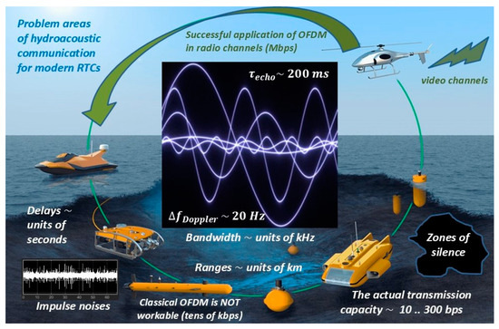
Figure 1.
Problem areas of hydroacoustic communication for modern RTCs.
2. Materials and Methods
2.1. Short Synchronizing Binary Sequences with the Best Autocorrelation Properties
In order to precisely measure distances, and to synchronize received data packets, noise-like pseudo-random codes with a sharpness of autocorrelation function (ACF), i.e., with minimum sidelobe levels, are used (codes such as Barker, M-sequences, Gold, Kasami, etc.). The use of short pulse signals (less than 10 ms) for synchronization and the channel impulse response estimation is usually difficult, due to the abundance of stochastic impulse noise in shallow waters associated with shrimp noise and ship movement [13,14,15,16,17,18].
The classical representation of a complex autocorrelation function is described by the expression . For a discrete signal , and the autocorrelation function has the following form:
Using high-performance computations, the authors have obtained a set of codes with lengths from 14–55 bits, with good autocorrelation properties, which are different from the well-known pseudo-random sequences. The obtained codes have better ratios of the maximum of the ACF to the maximum of the sidelobe level compared to the well-known pseudo-random sequences (Figure 2, Table 1). A specialized parallel computing algorithm was developed and used to analyze the entire code space for a given length.
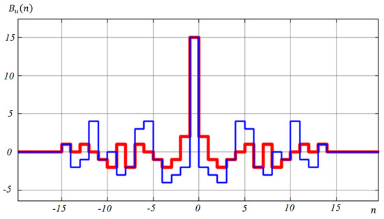
Figure 2.
Comparison of the ACF of two code sequences with a length of 15 elements, as follows: a non-periodic M-sequence 011010111000110 (blue) and a new code 000001110011010 (red) with sidelobe levels of ±4 and ±2 bits, respectively.

Table 1.
Parameters of found codes of length M from 14–55 bits. K, number of best codes.
For example, Figure 2 shows a comparison of the ACF of two code sequences with a length of fifteen elements, as follows: a non-periodic M-sequence and a new code.
The codes were obtained using a high-performance method whose algorithm enumerates codes from a code space with a priori known (to a degree) maximal levels of side lobes, as described in [19] in detail, as well as known equivalence classes of the codes based on the maximal value of the lobes. The algorithm stops when the space of the considered code has been exhausted, yielding a set of codes which meet the predicate that specifies the required ratio of the ACF shares. Found codes are stored in a database and later reused as necessary. Figure 3 shows the analytical estimation of a binary logarithm of time taken by the method in order to find codes whose side lobes of autocorrelation are less than MA bits, and, together with each other, constitute the mutual correlation with side lobes less than MV bits. The paper [19] describes the correlation of the measured performance with this prediction in detail, which is omitted here for brevity.
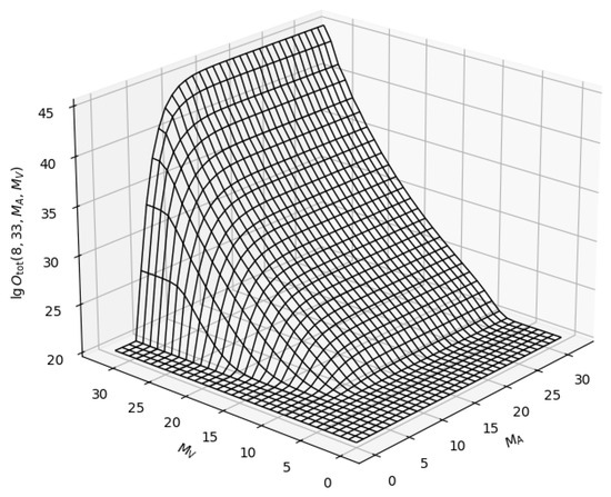
Figure 3.
Search time periods of 33-bit codes given different requirements to maximally allowed lobes of autocorrelation (MA) and mutual correlation (MV) sidelobe levels.
The collection of codes with lengths of 28, 42, 43, 45–48, and 51 elements are the most interesting, as they have the levels of side lobes of the autocorrelation function 2, 3, 3, 3, and 3, respectively (with respective ratios of 28/2, 42/3, 51/3), while for the known M-sequences with the lengths of 31 and 63 elements, the sidelobe level can be 6–8 bits.
For instance, we obtained 4 28-bit codes that were used as synchronizing signals in the tests described below. The respective values of the autocorrelation functions of the found 28-element sequences are shown in Figure 4.
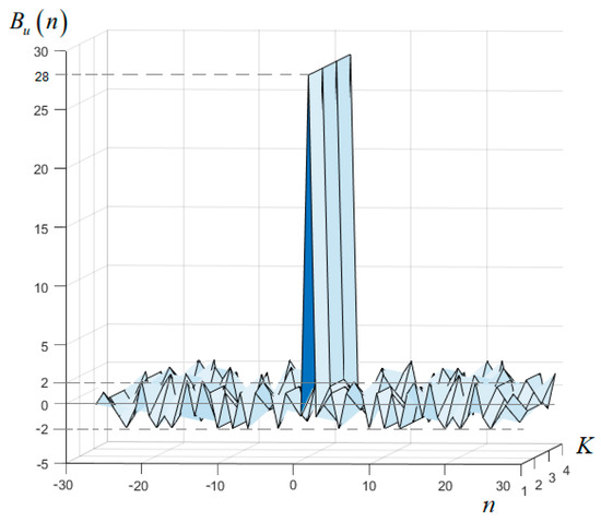
Figure 4.
Autocorrelation functions of the 4 obtained (K = 4) 28-element sequences with sidelobe levels not exceeding ±2 bits.
The ratio of the maximum of the ACF to the levels of the side lobes of the obtained codes compared to known codes ensures more accurate synchronization, with a minimal duration of synchronizing signals. The accuracy of the determined arrival time of the synchronizing signals is largely defined by the width of the main lobe of the autocorrelation function of the synchronizing signal, and the signal-to-noise ratio at the input of the correlator. A large reverberation time of the underwater audio channel can reduce the accuracy of the synchronization, as well as significantly limiting the bandwidth of the communication system. Furthermore, a preliminary estimation of the reverberation time in a hydroacoustic channel is made based on the synchronizing data sequence.
2.2. Multifrequency Signals with Constant Envelope CE-OFDM
In order to determine the impulse response of a hydroacoustic channel, it is necessary to know the volumetric geometry of the channel, its refractive properties—which, in fact, define the main paths of signal propagation—its beam amplitudes, and delays. According to [2], for the 10–18 kHz range, the temporal variations of the paths can range from 1–2 ms at the micro level and up to 150–250 ms at the macro level in deep seas (up to 2–3.5 km depth), with antennas submerged to depths of up to 200–400 m. One of the key factors in determining the data transfer rate and the minimum bit error rate (BER) is the reverberation time of the hydroacoustic channel.
The classical method of reduction of possible effects of intersymbol interference during data transmission on one carrier frequency is the addition of time guard intervals, , that are equal to the reverberation time in the hydroacoustic communication channel.
The information transfer rate at high values of the signal-to-noise ratio can be estimated using the following formula:
where is the duration of the information symbol; ; and M is the number of M-QAM manipulation positions (M is the position quadrature amplitude keying, whereas is the number of bits per data symbol to be transmitted).
Since , the expression shows the general relation between the data rate when using manipulation techniques, such as M-QAM, and the reverberation time in the channel. With guard interval values equal to hundreds of milliseconds, data transfer rates will not exceed values of several bits/s.
A commonly used effective tool for the reduction of negative effects of multipath propagation is the orthogonal frequency division multiplexing (OFDM) of N carriers, in combination with error-correction codes [20,21,22,23].
The bit-rate for OFDM can be estimated using the formula:
Here, is the frequency spacing between orthogonal OFDM subcarriers.
By using a significant number of carriers and transmitting them simultaneously in an orthogonal multiplexing format, it is possible to achieve data transmission rates of up to tens of kbit/s, which is usually an order of magnitude higher than the values that can be achieved using classical methods of bit sequence manipulation under similar conditions. However, reverberation in a hydroacoustic communication channel causes effects of significant selective fading by frequencies, reducing the signal-to-noise ratio for the carrier frequencies of the OFDM signal. Known algorithms for encoding multifrequency signals, as well as disadvantages of OFDM modulation associated with sensitivity to nonlinear distortions and Doppler effects, are given in [21,22,23,24,25].
The application of OFDM methods with a constant envelope (CE-OFDM) in hydroacoustic communication channels is not comprehensively covered in the literature, and here we propose a method for processing hydroacoustic signals, which is resistant to amplitude and slow-phase distortions that are typical for an underwater communication channel. Furthermore, the proposed signal processing algorithm is designed for significant multipath propagation in hydroacoustic environments, and it provides an acceptable information transfer rate. However, it is necessary to take into account that to increase in the information transfer rate and, therefore, the symbol transmission frequency in a hydroacoustic communication channel, the transmitted signal should withstand a rapid phase-change in the channel, and, at the same time, it is required to reduce significant time scattering in the channel.
Compared to existing algorithms, our approach relies on shorter base signals with reduced values of auto- and intercorrelation functioning at non-zero times, and this provides for greater transmission rates without a reduction in the reliability of the channels.
For hydroacoustic communication channels with a substantial reverberation time of up to 150–250 ms, and Doppler shifts of up to 15–25 Hz (for operating frequencies around 10 kHz and, for example, when the autonomous underwater vehicle (AUV) is moving at speeds of 1–2 m/s), it is essential to emit a signal in a frequency band that is narrower than the coherence band (1/250 ms = 4 Hz), while the signal bandwidth should be larger than the Doppler spectrum spreading (20 Hz) [26].
One of the key criteria for the applied digital modulation algorithm and its processing in hydroacoustics is its resistance to nonlinear distortions during amplification at the transmitter and during amplitude limitation at the receiver. Nonlinear amplification classes at emitters are also relevant for autonomous underwater systems due to the high efficiency of such amplifiers.
At the same time, OFDM systems have a number of disadvantages, such as requirements for linear amplification during signal emission and reception, problems of precise high-frequency and frame synchronization of symbols, and low resistance to Doppler effect frequency shifts. This list of problematic aspects leads to the search for additional algorithms; in particular, the use of angular modulation of OFDM symbols is proposed below (CE-OFDM).
If we use the model of a multifrequency signal as a normally distributed process (imaginary/real part of OFDM), then the normalization coefficient can be taken to be equal to , where σ is the RMS (root mean square) of the OFDM signal. The normalization operation is performed by considering the integral function of the probability density distribution of the amplitude of the Gaussian normal process. Performing the normalization procedure and OFDM angular modulation with a constant envelope will allow us to form the signal frequency band within the required boundaries. The OFDM signal as a result of normalization can be represented as follows:
where is the information symbol (s is the OFDM carrier number), formed by differential binary phase shift keying (DBPSK), as follows: , where is the bit source information flow of the s-th carrier of the multifrequency signal. Due to significant difficulties in implementing frame synchronization for classical OFDM, the use of differential encoding modes of OFDM symbols can be required for non-stationary channels.
The CE-OFDM (constant envelope OFDM) signal can be described by the following equality:
where is the center frequency of the spectrum.
It is known that OFDM signals are sensitive to nonlinear distortions, which can lead to an increase in the probability of errors in an implemented communication system. Therefore, one of the objectives of the proposed approach is to minimize frequency-phase distortions during the formation of CE-OFDM angular modulation and during signal detection at the receiver. For this purpose, we have proposed a method of signal generation in the form of a quadrature modulator/demodulator in an FPGA or DSP [27].
This allows us to find the signal-to-noise ratio value, , in the bandwidth of the modulating signal, where m is the modulation index, is a spectral power density, and is the bandwidth. It should be noted here that the use of small angular modulation values, , is appropriate to maintain an acceptable spectral efficiency of the CE-OFDM system.
The SNR value at the demodulator input is determined by the following expression: . Meanwhile, the coefficient of SNR variation at the input and output of the demodulator equals . Then, for the CE-OFDM system under Gaussian noise, the bit error probability (BER) is estimated by the following expression (6):
The main advantages and disadvantages of a CE-OFDM system with a constant envelope, compared to a standard OFDM system in multipath propagation, is that at small amplitudes of the reflected CE-OFDM signal, there is an effect of suppression of the reflected component; in the worst-case scenario, SNR at the output of the demodulator will not exceed the value of 18 for the OFDM signal [28].
The use of differential phase shift keying (DPSK) for the manipulation of symbols in the CE-OFDM system allows us to collect the energy of all multipath components in the interval of an OFDM symbol upon receival of the signal, provided that the duration of two OFDM symbols, together with guard intervals, does not exceed the coherence time of the hydroacoustic channel, which is as follows: .
These estimates show that for a receiver moving at the speed of m/s, the coherence time of the hydroacoustic channel will be ms. With the guard interval of ms in the CE-OFDM system, it is necessary to provide N = 16 carriers at the bit-rate of = 1143 bits/s.
3. Results and Discussion
The effectiveness of the developed methods was evaluated in a series of numerical and in situ experimental studies aimed at determining the stability of the proposed algorithms under different conditions of their possible operation, such as in water areas with high levels of reverberation and with significant Doppler shifts of the beam components.
Modeling. A series of numerical experiments was conducted using the Watermark acoustic simulator in the frequency range of 10–18 kHz. The Watermark hydroacoustic simulator is currently the standard for physical layer testing in underwater acoustic communication and navigation networks. It allows hydroacoustic communication system designers to test and compare physical layer calculation algorithms under reproducible and realistic marine environmental conditions. The Watermark simulator is a software shell in the MATLAB environment that is used to test simulated hydroacoustic channels and obtain a series of measurements obtained using models of real marine environments, including shallow water, in various frequency ranges with a non-stationary impulse response of the channel [29,30].
Table 2 shows the measurement conditions and parameters of a test channel named NCS1. For this test channel, the transmitter was placed near the bottom, and the receiver was a bottom-mounted hydrophone. The complexity of the model of the channel is of note, especially for communication systems using coherent reception, due to its rather short impulse response (Figure 5a, channel impulse response) with Doppler shifts of up to 16 Hz (Figure 5b,d, channel frequency shift and channel doppler spectrum). This channel has scattering both in the impulse response and in the spectrum, which overlap. Furthermore, this model has significant non-stationarity and instability of the phase characteristics over time—up to 20 s—and the phase shift reaches 570 degrees (Figure 5c, channel phase).
Table 2.
Measurement conditions and parameters of test channel NCS1.
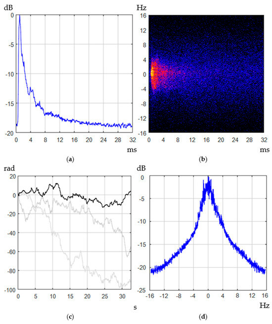
Figure 5.
Parameters of the hydroacoustic communication channel of NCS1 (540 m) (a) Channel impulse response, (b) Doppler shift in time domain (yellow dots—intensity 0 dB, red shade—intensity below –10 dB, blue—below –16 dB), (c) Channel phase (gray lines—phase shift in the channel in the next two 32-second time intervals), (d) Channel doppler spectrum.
In order to estimate the error probability per bit of information for the CE-OFDM method, a test was conducted to evaluate the impact of overlapping spectra and other measurement errors in the NCS1 communication channel. The main parameters for testing the CE-OFDM algorithm in the Watermark simulator, and for field tests, are the sampling frequency of 192 kHz; the signal bandwidth of kHz; the central emission frequency of kHz; a duration of the time guard interval between the CE-OFDM information packets of ms; the number of carriers, N = 100; the minimal frequency difference between carriers, Hz; the modulation index, m = 2; and the information exchange rate, = 1220 bits/s. Furthermore, the BER level was estimated for the parameters of N = 50, Hz, m = 4, and = 610 bits/s, and for N = 33, Hz, m = 6, and = 305 bits/s. The test results and error probabilities for the CE-OFDM method for the NCS1 channel are presented in Figure 6.
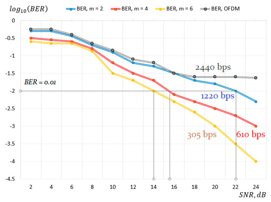
Figure 6.
BER level for the CE-OFDM and OFDM methods in the NCS1 Watermark channel.
Testing was performed at three values of the modulation index, m, which were equal to two, four, and six. Furthermore, for comparative tests in the simulation, testing of the classical OFDM method with similar differential encoding of information of multifrequency symbols of the OFDM signal was performed. The parameters for the classical OFDM method were chosen to be similar to those of the proposed OFDM-CE method ( ms, Hz, = 2440 bits/s).
For this type of channel (NCS1), with a reverberation time of 12–32 ms, classical manipulation methods do not provide a throughput higher than 60–80 bits/s; furthermore, with the implementation of classical OFDM manipulation, with symbol duration of 50 ms (with a guard interval of 16 ms, with a typical ratio of 50/16 = 3.125, and more), frequency differences between subcarriers of ∆ = 20 Hz would not meet the values of the Doppler shift in the channel (up to 16 Hz).
In this case, the usage of CE-OFDM makes it possible to avoid saturations of BER (SNR) at levels of classical OFDM (Figure 6), which usually occur due to selective frequency fading. Furthermore, the Doppler frequency shifts in this method lead only to a shift in the level of the constant component in the basic multifrequency signal, which has no effect on the error levels in the BER characteristics.
Numerical tests of the suggested CE-OFDM method in the NCS1 hydroacoustic channel simulator show an achievable throughput of 1220 bps at an SNR of 22 dB and higher to ensure a BER error probability of less than 10−2. Other modulation modes have an error level of 0.01 or less, at signal-to-noise ratio levels of 14 dB or more (Figure 6, yellow and red line).
In situ experiments. For the tests, a water area with a minimum level of noise from artificial sources was selected during the autumn season. The experiments were conducted at distances of up to 2 km, with a sea state of up to 2–3 points, which forms fairly high levels of non-stationarity of the underwater hydroacoustic communication channel. The receiving system in a sealed case (Figure 7) was located statically in a number of experiments, and also shifted at speeds of up to 1 m/s, moving away from the emitter. Field studies of the CE-OFDM method were conducted in the water area at a depth of 10–12 m, where in the bottom of the water area is sludge. The parameters of the communication system were as follows: center frequency,14 kHz; bandwidth, 8 kHz; power amplification class, B; sound pressure of radiation, 1 kPa; antenna submersion depth, 3 m (according to the measured sound speed profile); the antenna was unidirectional in the horizontal plane, and it was oriented vertically. The experimental setup, the receiving module, and the vertical profile of the sound speed distribution are shown on Figure 7.
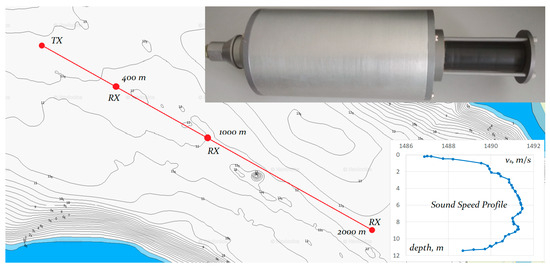
Figure 7.
Experimental setup, receiving module, and vertical profile of sound speed distribution.
We also employed underwater acoustic radiators in the radiation mode with a resonant frequency of 12 kHz, a respective sensitivity of 8 Pa/V, and a sensitivity in the receiving mode of 260 μV/Pa. Field experiments were aimed at determining the energy characteristics of the system, defining the error levels at given channel transmission rates, the average value of the reverberation time of the hydroacoustic channel, and the maximum data transmission range under given conditions. The experiment was carried out similarly to the numerical tests and included cyclic transmission of bit packets into the hydroacoustic communication channel without the use of error-correcting coding with the following packet structure: synchronization preamble (28-element code) and information packets that are modulated by the CE-OFDM algorithm.
The value of the guard interval between information packets, which is 32 ms, was chosen similarly to the numerical experiment. For the CE-OFDM symbol synchronization system, we used a 28-bit-long pseudo-random sequence emitted in the differential phase shift keying format at 14 kHz.
The response envelopes of the synchronizing matched filter to a 28-element preamble (black color, autocorrelation function) and to the received preamble signal (blue color) at a distance of 1000 m in an underwater hydroacoustic channel are shown in Figure 8; the preamble duration is 7 ms. The envelope response of the synchronizing matched filter to the 28-element preamble (blue) forms the synchronization peak (at 0.01 s) for subsequent frame synchronization of the CE-OFDM signal and its decoding.
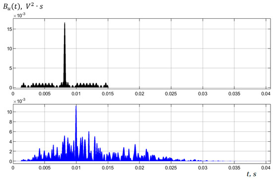
Figure 8.
Response envelopes of a synchronizing matched filter to a 28-element preamble (black, autocorrelation function) and to a received preamble signal (blue), at a distance of 1000 m in an underwater hydroacoustic channel. Preamble duration is 7 ms.
The blue representation of the response gives an idea of the impulse response of the underwater hydroacoustic channel, and the preliminary estimates show the magnitude of echo signals in the interval of 5–10 ms for this water area. As a result of the in situ tests, the relations between the BER and the transmission distance were obtained for the developed CE-OFDM method at a data rate of 1220 bps (Table 3).
Table 3.
Results of field tests for the developed CE-OFDM method at a data rate of 1220 bps.
The specified guard interval values for the marine experiments were excessive, since the actual reverberation time was about 5–10 ms at various signal reception locations and varied slightly as a result of increasing the transmission distance from 400 m–2000 m. The data rate could potentially be increased to 1818 bps at a similar level of BER. Determination of the reverberation time for the channel was performed by evaluating the correlator response to a 28-element synchronizing preamble.
The presented CE-OFDM method shows acceptable error probabilities at distances of up to 2000 m in the absence of noise-immune coders. The BER values obtained in sea tests and in the Watermark simulator are mainly due to selective fading by frequencies of individual carriers in the OFDM signal spectrum. The nonlinear distortions that take place during reception are also the cause of deterioration of the SNR at the output of the angular demodulator in the presence of reflected components at the receiver input, but they can be compensated by utilizing additional OFDM signal correction methods on the emitting and receiving sides.
4. Conclusions
This paper presents a method of OFDM digital modulation with a constant signal envelope for a hydroacoustic communication system by using new short synchronizing pseudo-random sequences found by the authors. The results of numerical tests in the Watermark simulator and natural experiments in shallow waters at distances of up to 2 km are presented. The proposed method allows for the use of class E/D power amplifiers in the emitter and the application of the limitation of the CE-OFDM signal amplitude at the receiver in order to eliminate the influence of powerful pulse interference. This method can be improved by using additional nonlinear algorithms for distortion correction to eliminate the effects of multipath propagation. A symbolic encoding algorithm using a DBPSK manipulation of a multifrequency OFDM signal with a constant envelope (CE-OFDM), conditioned upon the appropriate selection of parameters, such as the length of a guard interval and modulation index, can be suitable for multibeam non-stationary hydroacoustic environments with significant Doppler effect deviations of beam components.
In addition, this paper addresses the application of short pseudo-random sequences with better autocorrelation properties, found by the authors via numerical calculations, and used as synchronizing preambles for transmitted multifrequency OFDM packets. The implementation of these synchronizing sequences also provides highly efficient signal amplification modes and shortened emission timeslots, due to smaller code lengths and better autocorrelation properties of the proposed signals.
The proposed algorithms were validated on models (e.g., in the Watermark acoustic simulator) and in natural environments of shallow seas.
Author Contributions
Conceptualization, A.Y.R.; methodology, A.Y.R. and L.G.S.; software, A.A.C. and A.Y.R.; validation, D.A.K., M.M.S. and A.Y.R.; writing—original draft preparation, A.Y.R., A.A.C., M.M.S.; writing—review and editing, A.Y.R., M.M.S., L.G.S.; visualization, D.A.K.; All authors have read and agreed to the published version of the manuscript.
Funding
This article was a state assignment of the Ministry of Education and Science of Russia, in the field of scientific activity, under project No. FZNS-2023-0008.
Data Availability Statement
The original contributions presented in the study are included in the article, further inquiries can be directed to the corresponding author.
Conflicts of Interest
The authors declare no conflicts of interest.
References
- Yuh, J.; Ura, T.; Bekey, G.A. (Eds.) Underwater Robots; Springer Science & Business Media: New York, NY, USA, 2012; p. 251. [Google Scholar]
- Preisig, J. Acoustic propagation considerations for underwater acoustic communications network development. ACM SIGMOBILE Mob. Comput. Commun. Rev. 2007, 19, 2–10. [Google Scholar] [CrossRef]
- Lü, B.; Darmon, M.; Potel, C. Stochastic simulation of the high-frequency wave propagation in a random medium. J. Appl. Phys. 2012, 112, 054902. [Google Scholar] [CrossRef]
- Chitre, M.; Ong, S.H.; Potter, J. Performance of Coded OFDM in Very Shallow Water Channels and Snapping Shrimp Noise. In Proceedings of the OCEANS 2005 MTS/IEEE, Washington, DC, USA, 17–23 September 2005; pp. 996–1001. [Google Scholar]
- Scherbatyuk, A.P.; Dubrovin, F.S. Some algorithms of AUV positioning based on one moving beacon. IFAC Proc. Vol. 2012, 45, 1–6. [Google Scholar] [CrossRef]
- Sergeenko, N.; Scherbatyuk, A.; Dubrovin, F. Some Algorithms of Cooperative AUV Navigation with Mobile Surface Beacon. In Proceedings of the 2013 OCEANS-San Diego, San Diego, CA, USA, 23–27 September 2013; pp. 1–6. [Google Scholar]
- Dubrovin, F.; Scherbatyuk, A. Development of Algorithms for an Autonomous Underwater Vehicle Navigation with a Single Mobile Beacon: The results of Simulations and Marine Trials. In Proceedings of the 22nd Saint Petersburg International Conference on Integrated Navigation Systems, ICINS 2015-Proceedings, Saint Petersburg, Russia, 25–27 May 2015; pp. 164–171. [Google Scholar]
- Dubrovin, F.S.; Scherbatyuk, A.P. About Accuracy Estimation of AUV Single-Beacon Mobile Navigation using ASV, Equipped with DGPS. In Proceedings of the OCEANS 2016-Shanghai IEEE, Shanghai, China, 10–13 April 2016; pp. 1–4. [Google Scholar]
- Kebkal, K.G.; Kebkal, A.G.; Yakovlev, S.G. A frequency-modulated-carrier digital communication technique for multipath underwater acoustic channels. Acoust. Phys. 2004, 50, 177–184. [Google Scholar] [CrossRef]
- Lu, B.; Darmon, M.; Potel, C.; Zernov, V. Models Comparison for the scattering of an acoustic wave on immersed targets. J. Phys. Conf. Ser. 2012, 353, 012009. [Google Scholar] [CrossRef]
- Kebkal, K.G.; Mashoshin, A.I. AUV acoustic positioning methods. Gyroscopy Navig. 2017, 8, 80–89. [Google Scholar] [CrossRef]
- Proakis, J.G.; Stojanovic, M.; Catipovic, J. Adaptive Equalization Algorithms for High Rate Underwater Acoustic Communications. In Proceedings of the IEEE Symposium on Autonomous Underwater Vehicle Technology (AUV′94), Cambridge, MA, USA, 19–20 July 1994; pp. 157–164. [Google Scholar]
- Petrov, P.S.; Golov, A.A.; Bezotvetnykh, V.V.; Burenin, A.V.; Kozitskiy, S.B.; Sorokin, M.A.; Morgunov, Y.N. Experimental and theoretical study on arrival times and effective velocities in the case of long-range propagation of acoustical pulses along the shelf edge in a shallow sea. Acoust. Phys. 2020, 66, 21–32. [Google Scholar] [CrossRef]
- Morgunov, Y.N.; Bezotvetnykh, V.V.; Golov, A.A.; Burenin, A.V.; Lebedev, M.S.; Petrov, P.S. Experimental study of the impulse response function variability of underwater sound channel in the Sea of Japan using pseudorandom sequences and its application to long-range acoustic navigation. Acoust. Phys. 2021, 67, 287–292. [Google Scholar] [CrossRef]
- Morgunov, Y.N.; Golov, A.A.; Kamenev, S.I.; Matvienko, Y.V. Means and methods for hydrological–acoustic support of high-precision long-range positioning of underwater objects. Acoust. Phys. 2019, 65, 711–715. [Google Scholar] [CrossRef]
- Morgunov, Y.N.; Burenin, A.V.; Besotvetnykh, V.V.; Golov, A.A. Propagation of pulse pseudorandom signals from a shelf into shallow water in winter hydrological conditions of the Sea of Japan. Acoust. Phys. 2017, 63, 681–685. [Google Scholar] [CrossRef]
- Morgunov, Y.N.; Bezotvetnykh, V.V.; Burenin, A.V.; Voitenko, E.A. Study of how hydrological conditions affect the propagation of pseudorandom signals from the shelf in deep water. Acoust. Phys. 2016, 62, 350–356. [Google Scholar] [CrossRef]
- Rodionov, A.Y.; Unru, P.P.; Kirianov, A.V.; Dubrovin, F.S.; Kulik, S.Y. Some Algorithms for DSSS Signal Processing with Time-Shift Keying for Long-Distance Underwater Communication. In Proceedings of the 2017 IEEE Underwater Technology (UT), Busan, Republic of Korea, 21–24 February 2017; p. 7890287. [Google Scholar]
- Chusov, A.A.; Kovylin, A.A.; Statsenko, L.G.; Mirgorodskaya, Y.V. Parallel search for signals with specified cross-and autocorrelation properties on multiprocessor platforms. Radioelectron. Commun. Syst. 2011, 54, 425–431. [Google Scholar] [CrossRef]
- Van Walree, P.; Sangfelt, E.; Leus, G. Multicarrier spread spectrum for covert acoustic communications. In Proceedings of the MTS/IEEE OCEANS, Quebec City, QC, Canada, 8–11 April 2008; pp. 1–8. [Google Scholar]
- Zhou, S.; Wang, Z. OFDM for Underwater Acoustic Communications; John Wiley & Sons: New York, NY, USA, 2014; p. 416. [Google Scholar]
- Rodionov, A.Y.; Statsenko, L.G.; Kuzin, D.A.; Smirnova, M.M. Application of incoherent multi-frequency signals for information transmission in a nonstationary hydroacoustic environment. Acoust. Phys. 2023, 69, 738–747. [Google Scholar] [CrossRef]
- Berger, C.R.; Huang, J.; Moura, J.M. Study of pilot overhead for iterative OFDM receivers on time-varying and sparse underwater acoustic channels. In Proceedings of the OCEANS′11 MTS/IEEE KONA, Waikoloa, HI, USA, 19–22 September 2011; pp. 1–8. [Google Scholar]
- Chitre, M.; Shahabudeen, S.; Stojanovic, M. Underwater acoustic communications and networking: Recent advances and future challenges. Mar. Technol. Soc. J. 2008, 42, 103–116. [Google Scholar] [CrossRef]
- Weichman, P.B. Doppler effects in heterogeneous media with applications to ocean acoustic modeling. Nonlinear Soft Matter Phys. 2005, 72, 066602. [Google Scholar] [CrossRef] [PubMed]
- Sklar, B. Digital Communications: Fundamentals and Applications; Pearson Education: London, UK, 2021; p. 1136. ISBN 9780134588667/0134588665. [Google Scholar]
- Rodionov, A.Y.; Unru, P.P.; Statsenko, L.G.; Kir’yanov, A.V.; Chusov, A.A.; Scherbatyuk, A.F. Development of the Preamble-based FM-OFDM Underwater Acoustic Communication System Using High-Performance Computing. In Proceedings of the 2016 17th International Conference on Sciences and Techniques of Automatic Control and Computer Engineering (STA), Sousse, Tunisia, 19–21 December 2016; pp. 697–704. [Google Scholar]
- Rodionov, A.; Statsenko, L.; Unru, P.; Morgunov, Y.; Golov, A.; Voitenko, E.; Kiryanov, A. Experimental estimation of the constant envelope fm-ofdm method usage in underwater acoustic communication systems. Appl. Sci. 2018, 8, 402. [Google Scholar] [CrossRef]
- Van Walree, P.A.; Jenserud, T.; Smedsrud, M. A discrete-time channel simulator driven by measured scattering functions. IEEE J. Sel. Areas Commun. 2008, 26, 1628–1637. [Google Scholar] [CrossRef]
- van Walree, P.; Otnes, R.; Jenserud, T. Watermark: A Realistic Benchmark for Underwater Acoustic Modems. In Proceedings of the 2016 IEEE Third Underwater Communications and Networking Conference (UComms), Lerici, Italy, 30 August–1 September 2016; pp. 1–4. [Google Scholar]
Disclaimer/Publisher’s Note: The statements, opinions and data contained in all publications are solely those of the individual author(s) and contributor(s) and not of MDPI and/or the editor(s). MDPI and/or the editor(s) disclaim responsibility for any injury to people or property resulting from any ideas, methods, instructions or products referred to in the content. |
© 2024 by the authors. Licensee MDPI, Basel, Switzerland. This article is an open access article distributed under the terms and conditions of the Creative Commons Attribution (CC BY) license (https://creativecommons.org/licenses/by/4.0/).