Abstract
This paper proposes a NCPM (Nano-composite coated permanent magnets)-based IPMSM (Interior Permanent Magnet Synchronous Motor) electric drive system, especially applicable for electric vehicles (EV). For an EV, an increase in the “T/A (torque per ampere)” condition is highly recommended, as it directly affects the maximum distance run by EV on a single charge. Due to NCPM, a substantial increase in magnetic flux intensity, resistance to corrosion and Curie temperature are observed. As a result, the proposed drive clearly exhibits a higher power to weight ratio. Also, it is capable of delivering higher T/A to the drive system without any considerable change in two important factors of EV: (1) mass and volume of the drive system (2) battery capacity of the drive system. Moreover, NCPM performance is less susceptible to temperature variation, which makes it an appropriate candidate for vehicular applications, where temperature inconsistency could be a common issue during working conditions. Also, NCPM-based IPMSM offers a quicker speed response than conventional IPMSM, thus providing higher acceleration, which is one of the important performance factors for vehicular applications. A vector controlled mathematical model of IPMSM and NCPM-based IPMSM is tested for various speed commands. Also, the NCPM-based IPMSM, in the proposed configuration, is fed from a three-level DCMLI (diode clamped multi-level inverter), as the drive system is considered for medium to high power applications. A comparative performance analysis is carried out between the proposed drive system and a conventional IPMSM-based drive system using MATLAB/SIMULINK to indicate the efficacy of the proposed configuration.
1. Introduction
With the rising worldwide challenge of global warming and air pollution, conventional vehicles running on petroleum fuels are prominent and easy-to-blame culprits. Thus, the upsurge of electric vehicles (EVs) in terms of commercial product development and research is quite evident for the past many years. Especially in developing nations like India, research and development on EVs and their related components are considered to be at their peak. One of the most important factors, in reference to EVs, that creates a level of fear and anxiety among customers and is a clear obstacle to its mass acceptance, is the maximum distance capacity of an EV to go on a single charge of the battery. Moreover, the battery size and weight is a major constraint for an EV design, as it affects its performance parameters like speed, maximum torque capacity, efficiency, etc. Thus, the size and capacity of the battery system included in an EV are also limited.
In recent times, a very strong development in research activities, in reference to EV batteries and their charging technology is observed around the globe. This particular development is obviously directed towards the enhancement of EV performance, thus, in turn, making it more acceptable among the common masses. However, EV battery and their charging-related domain is not the only aspect of EV performance enhancement. The motor of the EV drive system is also a very important component, which plays a very crucial role in improving its performance. Among the electric motors applicable for EV drive applications [1,2], PM (permanent magnet) machines are a very popular choice among the major EV manufacturers worldwide. Among the several types of PM machines, IPMSM (interior permanent magnet synchronous motor) is a popular choice for personal four-wheeler EV applications.
Several design analyses and performance studies have been carried out for IPMSM, specifically for EV applications [3,4,5,6,7,8,9,10], such as segmented IPMSM [3], a multilayer IPMSM [5], concentrated-winding-based IPMSM [6], Neodymium sintered-magnet-based IPMSM [7], and optimization of IPMSM magnet shape [10]. In line with this chain of technical advancements in the design and structure of IPMSM, an NCPM (nano-composite coated permanent magnets)-based IPMSM is proposed and analyzed in this manuscript for EV applications.
Nano-composite material, in the current scenario of technical advancement, holds a degree of high usage importance, primarily because of boosting the magnetic properties [11]. The magnetic core material in the form of nano-composite “NiCuZn” ferrite offers high magnetization, high resistivity, high curie temperature, and permittivity. Henceforth, these ferrites play a vital role in various technical domains such as electromagnetic interference (EMI) suppressors, microwave devices, SMPS (switched mode power supply), telecommunications, etc.
Nano-composite material NiCuZn is deposited as thin films on permanent magnets using different methods [12,13]. The electron-beam approach has substantial benefits in terms of stoichiometry and film quality. The e-beam technique of CIGS film deposition removes the secondary salinization procedure required in other methods of CIGS (copper indium gallium selenide) film preparation. E-beam has been used to fabricate CuIn0.5Ga0.5Te2 and CuIn0.85Ga0.15Se2 thin films from bulk alloys. The alloys were created by direct synthesis and crystallization after the stoichiometric components had been completely melted. Bulk material preparation is a time-consuming and costly process as compared to ball milling powder manufacturing. This work adopts the electron deposition method used for coating. High surface quality, thick smooth coatings, very low optical losses, extremely low scattering, very strong run-to-run process repeatability, outstanding uniformity, maximum flexibility, and a variety of applications are the key advantages of electron deposition.
In [14], four lithium-iron-phosphate cells are linked in series to form a lithium-ion battery module. The module underwent a test profile that includes a fast-charge phase at a current rate of 3 C to determine the effects of rapid charge on the module. This testing profile mimicked the actual operating profile needed by an electric bus’s batteries to provide a specific local public transportation service, including battery recharging at the end of the line. Over 3000 shallow cycles were carried out. In [15], a conventional heavy-duty truck operating over long distances and a parallel hybrid vehicle’s life cycle analysis are compared. The environmental costs of manufacture are calculated using a uniform vehicle glider and just the different components of the two drivetrains. A feed-forward controller based on an analytical representation of a permanent magnet synchronous motor (PMSM) was developed with the goal of addressing the torque ripple problem of direct torque control, which is caused by the spatial harmonics as well as magnetic saturation characteristics of PMSM [16,17]. In [18], an axial flux induction motor (AFIM) with a single stator and rotor is mathematically modeled. The model depends on the electromagnetic torque equation, which depicts the relationship between two independent variables: the flux density in the air gap and the axial length of the stator core.
In order to accomplish the desired brushless operation, this research suggests a unique stator sub-harmonic magneto motive force (MMF)-based brushless synchronous machine architecture. This new topology uses a sub-harmonic MMF component that is one-fourth the size of the fundamental MMF component [19,20]. The exact magnetic adjustment of HPMSM (high speed permanent magnet synchronous machine) has become more challenging because of the cross-coupling impact of high- and low-coercive permanent magnets. In this article, two techniques—adding magnetic barriers and activating coils—are employed to mitigate the cross-coupling effect [21]. For use in electric vehicle (EV) applications, this study examines and contrasts the electromagnetic performance and torque-generating capacities of AIM (advanced non-overlapping winding induction machines), CIM (conventional induction machines), and IPM (internal permanent magnet) machines [22]. With a focus on the air gap flux density, the current study intended to predict the electromagnetic characteristics of flux-switching permanent magnet machines (FSPMMs). The former was first developed without taking into account the slotting effect at both ends of the air gap. The resultant flux density spatial repartition was then adjusted to include stator and rotor permeance functions that had to take the slotting effect and the PM flux concentrating arrangement into account [23,24].
The use of a unique kind of thermal interface material (TIM) in an electric motor with an air-gap winding is described in this paper. The TIM is represented by three industrially produced electrically insulating pressure-sensitive adhesive (PSA) tapes. First, experimental research on the adhesion performances of the winding procedure was performed [25]. In order to enhance the motor control performance of a three-phase four-switch (TPFS) inverter-fed permanent magnet synchronous motor (PMSM) drive system, this research offers a suppression approach of the capacitor voltage offset based on reference voltage self-correction [26]. This study proposes an enhanced You Only Look Once v4 (YOLOv4) real-time machine vision-based target identification approach for monitoring the location using current monitoring equipment, send real-time video data, increase the monitoring range, and considerably lower the cost of usage [27]. The back electromotive force (EMF) waveforms of two permanent magnet machines with the same primary dimension—a flux switching machine (FSPM) and a variable flux memory machine (VFMPM)—were compared in this work [28].
The permanent magnet torque motor (PMTM) has several benefits including high torque density, low torque ripple, robust overload capacity, and is extensively used in aircraft, machine tools, industrial robots and CNC (computer numerical control). The demands on torque motor performance have increased in line with the modernization of industrial production [29,30]. Ref. [31], in order to achieve the torque and speed requirements for the dependable operation that satisfies the criteria of an electric propulsion system, describes how a five-phase permanent-magnet synchronous motor functions under one- or two-phase failures. This paper proposes a broad speed range operation control technique based on flux-weakening control and an over-modulation method for an indirect matrix converter-surface mounted permanent magnet synchronous motor drive (IMC-SPMSM) [32,33]. The Element-Free Galerkin technique (EFG) is used in this work to describe flexoelectricity in a composite material. For the partial differential equations (PDEs) to adequately explain the electromechanical interaction, the strain gradient term must be included [34,35]. This need is met by the developed model’s usage of quartic weight functions [36].
The following primary goals are addressed in this paper’s thorough analysis:
- To examine the electro-deposition of a NiCuZn nanocomposite based on polyethylene glycol with permanent magnet material.
- The resulting coated permanent magnets’ magnetic characteristics are assessed using a hysteresis loop tester, and their microstructure is investigated using X-ray diffraction (XRD) and scanning electron microscopy (SEM). By using linear polarization, their corrosion resistance is assessed.
- A comparison of the performance of IPMSMs based on NCPM and those based on traditional IPMSM for various speed command types.
- A performance comparison between the proposed EV drive’s conventional IMPMSM drive and the DCMLI-fed NCPM-based IPMSM drive to show its effectiveness.
2. Nano-Composite with PM Material
This section provides specifics of coating a Nano-composite coat on PM: the nano-composite Ni0.69Cu0.13Zn0.18Fe2O4 is prepared by citrate precursor method before use. Polyethylene glycol (H−(O−CH2−CH2)n−OH, denoted as PEG) (Sigma, Maharastra, India, 99.8%), Permanent Magnet material is utilized as procured. The eutectic blend is formulated by mixing Polyethylene glycol in the ratio of 1:2 (molar) at 70 °C till a consistent and transparent liquid is obtained. Consequently, a definite quantity of metal chloride is supplemented and mixed, with unaltered settings. The electrolyte composition being studied is discussed thereafter.
2.1. XRD Pattern
X-ray diffraction analysis (XRD) is commonly used to determine the chemical composition as well as phase structure of a material. The X-ray diffraction facility offers high-quality diffraction data for powder specimens as well as single crystals [36]. The XRD analysis of tested samples was carried out by Bruker D8 Advance Twin-Twin and Bruker Kappa Apex II Diffractometer (Andhra University, Visakhapatnam, India) for powder and single-crystal, respectively. Powders were deposited in a metal mold affixed to a glass slide prior to measurement; final coatings were examined without additional treatment. The measurements were taken using an angular range of 2θ = 10–90° and a scan rate of 0.04° per second. XRD evaluation was used to assess the data.
The structure of the crystal and various phases of deposits are analyzed with XRD (X-ray diffraction) by a Rigaku smart-lab diffractometer in the Bragg−Brentano geometry, furnished with a D/teX Ultra 250 detector (Andhra University, Visakhapatnam, India) and a CuKα target (1.540 Å). The rate of scanning is 15° per min, and 0.03° is the step size.
Figure 1 gives the XRD pattern of Ni0.69Cu0.13Zn0.18Fe2O4nano-composite-coated permanent magnet as a single-phase cubic spinel structure. It is a plot between crystal particle size intensity (cps) and diffraction angle (2θ). It is utilized to detect contamination in a desired nano-composite composition is known from the XRD pattern [37]. From the XRD plot, it can be observed that no undesirable secondary phases are present.
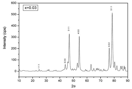
Figure 1.
XRD pattern of Ni0.69Cu0.13Zn0.18Fe2O4 Nano-composite-coated permanent magnets.
The broadened diffraction peaks indicate that the coated permanent magnets can be characterized as ultrafine particles.
2.2. SEM and EDX Analysis
Scanning electron microscopy (SEM) is a technique for observing materials at the nano- and micro-scales. SEM enables high-resolution observation, allowing for more precise monitoring of the microstructure [38]. To provide a more precise picture contrast and to avoid alteration, tested samples need to be electrically conductive. Thin layers of a conductive film are utilized in the case for non-conductive materials. In the current study, a scanning electron microscope (SEM-EDAX:/Oxford Mx xN), was used to investigate the particle shape, size, and microstructural changes of the synthesized coatings. A little quantity of powder was deposited on top of conductive carbon tape to prepare powders for SEM analysis. To produce high-resolution photographs, the tested powders and coatings were coated with a tiny conductive layer of carbon.
EDX systems include attachments to Scanning Electron Microscopy (SEM) instruments, where the imaging capabilities of the microscope detects the specimen of interest. EDX analysis produces spectra with peaks that correspond to the elements that make up the real composition of the material being analyzed. Image analysis and element mapping to a sample are additional options. EDX becomes extremely strong in multi-technique approaches, notably in contamination analysis and industrial forensic science examinations [39]. The method might be qualitative, semi-quantitative, or quantitative, and it can also offer the geographical distribution of items via mapping.
The morphology of the surface is analyzed with SEM (scanning electron microscope) utilizing an FEI Quanta 400 FEG/EDAX Genesis X4M microscope. It is utilized to identify contaminant size and structure.
Figure 2 shows the SEM image and EDX (Energy Dispersive X-ray) analysis of the composite-coated permanent magnet. These characteristics were obtained from the PEG-based Ni0.69Cu0.13Zn0.18Fe2O4 nano-composite using the electrolyte composition. From Figure 2, it can be observed that the Ni0.69Cu0.13Zn0.18Fe2O4 nano-composite has a porous form comprised up of tiny particles [40,41]. The benefits of EDX analysis include increased quality control, process optimization, quick detection of contaminants and sources, and determining the root cause of a problem in the process chain.
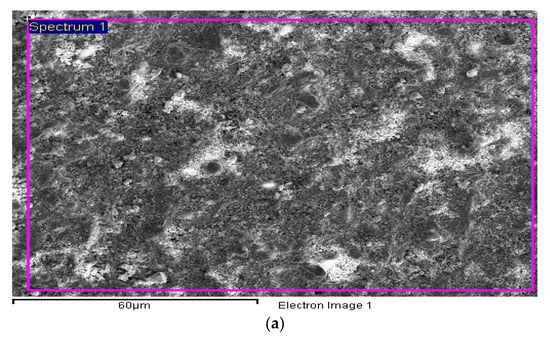
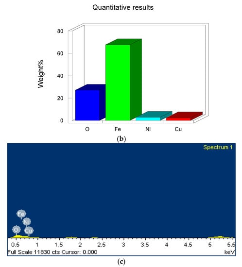
Figure 2.
Surface morphology of NCM (Ni0.69Cu0.13Zn0.18Fe2O4) coated PM: (a) SEM image; (b) EDX image; (c) quantitative analysis from the EDX image.
2.3. Corrosion Pattern
Potentio-dynamic polarization properties obtained using 3.5% NaCl aqueous solution with a scan rate of 1 mV/s are used to assess the corrosion behavior exhibited by the coated permanent magnets. Figure 3 depicts the corrosion potential (Vcorr) and corrosion current density (Jcorr) retrieved from Tafel plots. The Vcorr value for the permanent magnets obtained is −840.6 mV. It has been verified that the coating of Ni0.69Cu0.13Zn0.18Fe2O4 nano-composite on the permanent magnet modifies the anti-corrosion properties of the film, whereas the Ni0.69Cu0.13Zn0.18Fe2O4 nano-composite-coated permanent magnets prepared exhibited the low Vcorr with a value of −621.1 mV. This property is much more advantageous for under water vehicles.
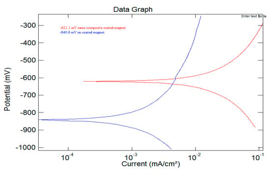
Figure 3.
Potentio-dynamic polarization characterization.
2.4. B-H Curve
The magnetic properties of the coated permanent magnets are investigated using a hysteresis loop tester. At nominal room temperature, we have a characteristic hysteresis loop (M(H)) of the PM, with respect to the parallel and perpendicular magnetic field to the plane of the film. Likewise, the M(H) pattern is analyzed for Ni0.69 Cu0.13 Zn0.18 Fe2O4 nano-composite-coated permanent magnet obtained with the PEG-based sample. The hysteresis curves clearly show that the PMs were simpler to magnetize and demagnetize using small coercive fields (HC), which are well-suited for softer magnetic materials. It can be observed that the magnetic properties such as magnetic flux density, remanent flux, coercivity, and BHmax are shown in Table 1. The coercive field in reference to the film plane (HC) varies between 50 to 20 KOe for the PMs prepared from the PEG-based Ni0.69 Cu0.13 Zn0.18 Fe2O4 nano-composite-coated PM.

Table 1.
Magnetic parameters of coated and uncoated magnets.
3. Results and Discussion
The IPMSM drive with vector control is shown in Figure 4 using a mathematical model. In contrast to conventional IPMSM, NCPM-based IPMSM has a higher flux density. A closed-loop control is built on the vector control, where id(ref) has been set to 0. Figure 5 illustrates the results of a comparison study between traditional IPMSM and NCPM-based IP-MSM for various speed command types over a period of 1500 s. For both systems, the torque command is maintained constant as a step torque command, as seen in Figure 6. Table 1 displays the model parameters for both systems. In these mathematical models, all values are recorded in units. Table 2 shows the two categories, C1 and C2, are used to categorize all observations. The components of C1 are the torque response (Te), the speed response (r) (both command value (red) and actual value (blue)), and the d- and q-axis current responses (Isd and Isq). The components of C2 are as follows: rotor position (rs), d-axis voltage (usd), and q-axis voltage (usq) in that order; x-axis current (Isx), y-axis current (Isy), f-axis flux (fsx), y-axis voltage (fsy), and usx, usy, respectively.
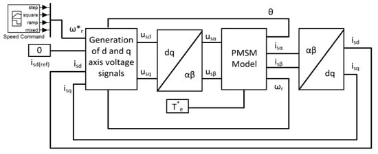
Figure 4.
IPMSM drive with vector control.
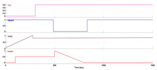
Figure 5.
Different speed commands.

Figure 6.
Torque step command.

Table 2.
IPMSM mathematical model parameters.
First, Figure 7a,b (Red line Indicate input and blue line indicate output.) correspond to the traditional IPMSM’s responses to a step speed instruction in terms of C1 and C2, respectively. Figure 7a shows that throughout the simulation period, the motor’s speed response was unable to reach the reference value and was only loosely following the reference. Additionally, the sudden speed command causes a sudden drop in the d-axis current, whereas the sudden decrease in the torque command does not affect the q-axis current at all. The NCPM-based IPMSM’s C1 and C2 responses are shown in Figure 8a,b. Figure 8a makes it clear that the motor speed closely resembles the speed command, but does so much more quickly, making it easy to see throughout the simulation period. In addition, the d-axis current is fixed at the reference value it has been assigned, but the q-axis current decreases as the speed approaches the predetermined value. In addition, because the motor reaches the desired speed, the flux pattern from C2 (Figure 8b) and component is greatly reduced as compared to the traditional IPMSM, as shown in C2. Figure 9a,b show the response of a standard IPMSM in terms of C1 and C2, respectively, for the second example of a square speed command. The speed of the PMSM does not approach the reference in the simulation time, as can be shown in Figure 9a.
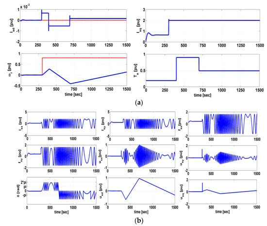
Figure 7.
Conventional PMSM performance with step speed. (a) C1; (b) C2.
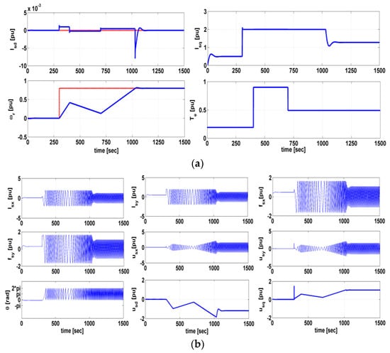
Figure 8.
NCPM - based PMSM performance with step speed. (a) C1; (b) C2.
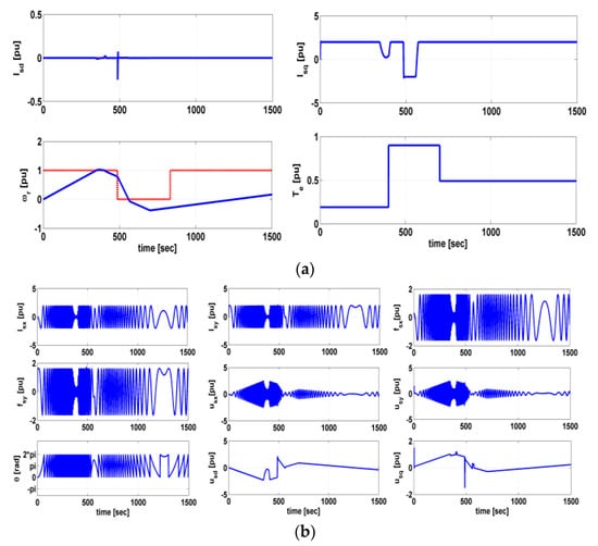
Figure 9.
Conventional IPMSM performance with square speed command. (a) C1; (b) C2.
The NCPM-based IPMSM’s C1 and C2 responses are shown in Figure 10a,b. Figure 10a clearly illustrates how the motor speed adopts the speed reference for the selected simulation time. Since the motor reaches the desired speed, the flux pattern from C2 (Figure 10b) for the components and component also becomes less pronounced in comparison to that of a conventional IPMSM. Figure 11a,b show the typical IPMSM response for categories C1 and C2 when the ramp speed command input is used. Figure 12a,b show, respectively, the NCPM-based IPMSM response for the ramp input in terms of category C1 and C2. From C1 of both systems, it is pretty obvious how quickly each system responds differently. Additionally, the flux component for the proposed system is maintained at the same value as seen in Figure 11b and Figure 12b, whereas it decreases with the achievement of the speed command.
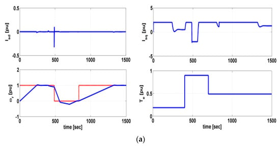
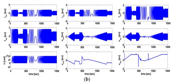
Figure 10.
NCPM-based IPMSM performance with square speed command. (a) C1; (b) C2.
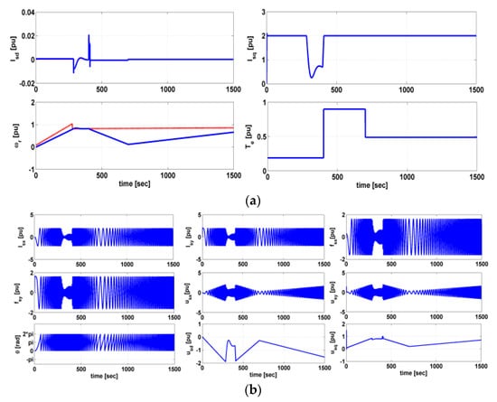
Figure 11.
Conventional IPMSM performance with ramp speed command. (a) C1; (b) C2.
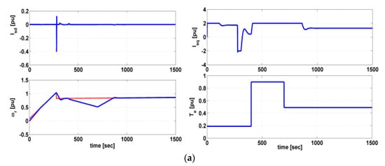
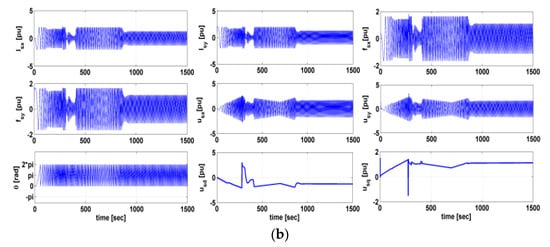
Figure 12.
NCPM - based IPMSM performance with ramp speed command. (a) C1; (b) C2.
Figure 13 and Figure 14 demonstrate, respectively, the responses for the proposed NCPM-based IPMSM and the traditional IPMSM, for the final speed command type of mixed input described in Figure 5. The speed response of the traditional IPMSM (Figure 13a) lags behind the proposed NCPM-based IPMSM (Figure 14a), even if the speed command ultimate intended value is arriving at 0, or the rest position. As a result, it can be said with confidence that the proposed NCPM-based IMPSM with vector control performance is found to be more responsive than IPMSM for a variety of speed instructions.
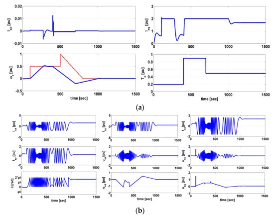
Figure 13.
Conventional IPMSM performance with mixed speed command. (a) C1; (b) C2.
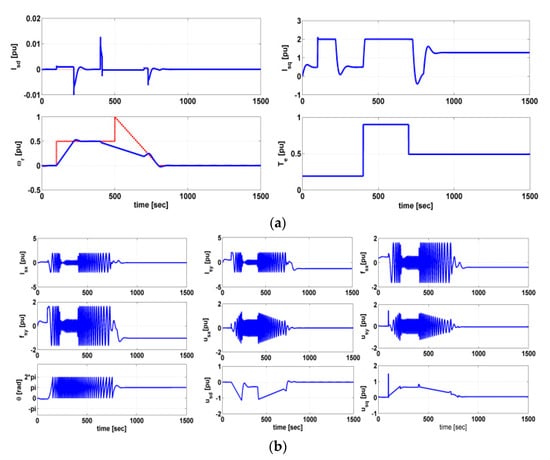
Figure 14.
NCPM-based IPMSM performance with mixed speed command. (a) C1; (b) C2.
The DCMLI-fed IMPMSM drive with vector control block diagrams shown in Figure 15 and Figure 16 present the three level diode-clamped multi-level inverter simulation model.
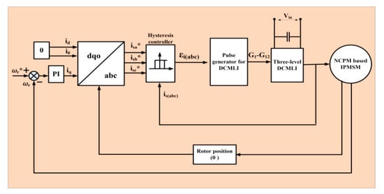
Figure 15.
DCMLI-fed IMPMSM drive with vector control. * represents the complex conjugate.
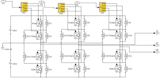
Figure 16.
Three levels diode-clamped multi-level inverter.
4. Comparative Analysis of Vector Controlled IPMSM with and without NCPM
The proposed DCMLI-fed NCPM-based IPMSM drive is analyzed using MATLAB/SIMULINK R2014a with regard to several performance parameters. Moreover, in order to establish its effectiveness, a comparative performance analysis is also presented in reference to a conventional IPMSM drive fed from a similar three-level DCMLI. The control algorithm implemented for the drive is the constant torque angle control method as discussed in the section. Several operating conditions are considered for effective performance analysis such as initial torque demand response, speed demand response, transient response to change in torque demand (increment and decrement), transient response to change in speed demand (increment and decrement), the voltage across the motor terminals, motor current response, torque per ampere response.
4.1. Fixed Load Condition
At instant 0.3 s, a fixed torque demand of 40 Nm is set for both the drive systems. It is clear from Figure 17a,b that both drive system responds to the torque demand of 40 Nm. Figure 18 indicates the torque ripple content for both drives. The conventional IPMSM drive takes more time to settle at the set value and also the torque ripple content is higher than the corresponding NCPM-based IPMSM drive. When compared to the other drive, the suggested drive has 40% reduced torque ripple.
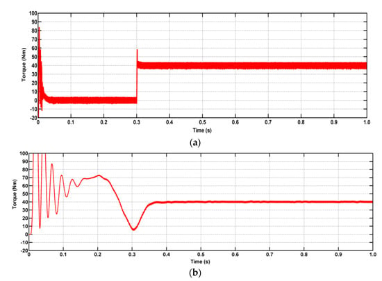
Figure 17.
Torque response with fixed load. (a) Conventional IPMSM drive; (b) NCPM-based IPMSM drive.
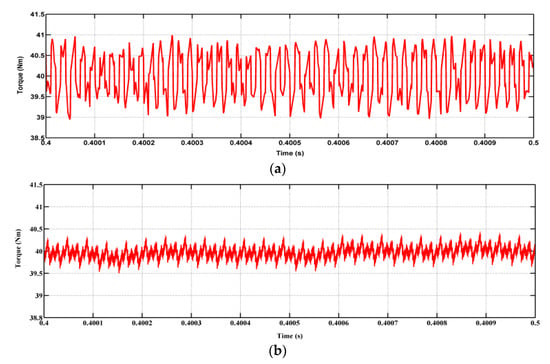
Figure 18.
Torque ripple response. (a) Conventional IPMSM drive; (b) NCPM-based IPMSM drive.
Figure 19a,b depict the torque density response for both drive systems. As stated earlier, that NCPM-based IPMSM drive would draw less current from the supply for the same amount of torque demand compared to the conventional system, as evident from the results.
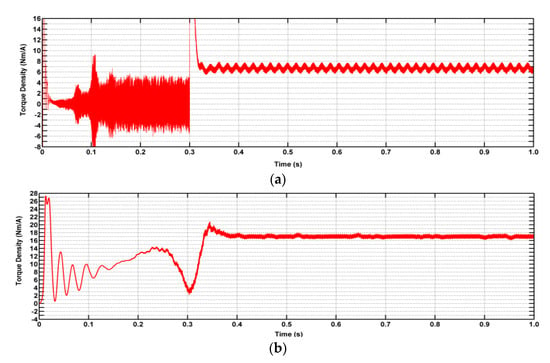
Figure 19.
Torque density. (a) Conventional IPMSM drive; (b) NCPM-based IPMSM drive.
Also, this implies the fact that for the same current rating, the drive would be able to produce more torque, thus making the system more powerful for the same mass, size, and rating of the battery system in EVs. The torque density is raised by almost 30% with NCPM-based IMPSM drive system.
4.2. Variable Load Condition
Figure 20a,b illustrate the torque response by both the drive system under variable load situations. The torque demand by the load is increased in the following order with respect to specific time instant, time instant (s): [0, 1, 2, 2.5], torque demand corresponding to a respective time instant: [20, 40, –20, –30]. As is clear from the result, the torque response by the proposed drive system is much more rapid, with less response time. Also, the ripple content is higher in the torque response by the conventional drive system.
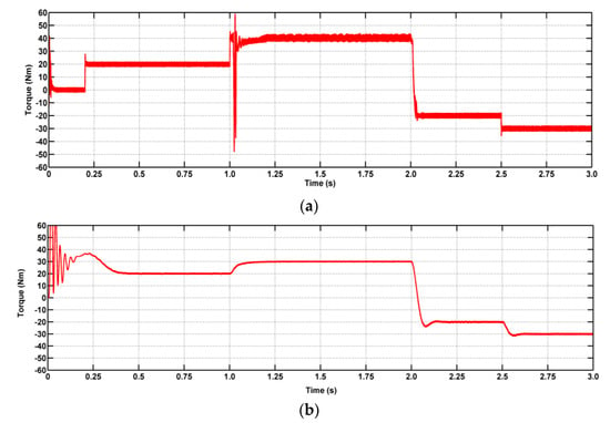
Figure 20.
Torque response with variable load. (a) Conventional IPMSM drive; (b) NCPM-based IPMSM drive.
5. Discussion
An exploration the electro-deposition of a NiCuZn nanocomposite based on polyethylene glycol with permanent magnet material, among other things, is one of the primary goals of the extensive investigation reported in this work. The magnetic characteristics of the acquired coated permanent magnets are assessed using a hysteresis loop tester, and the X-ray diffraction (XRD) and scanning electron microscopy (SEM) methods are used to investigate the microstructure. By using linear polarization, you can assess their corrosion resistance. A comparison of the effectiveness of traditional IPMSM and IPMSM based on NCPM with respect to their mathematical models for various speed orders. A performance comparison between the proposed EV drive and the traditional IMPMSM drive using DCMLI-fed NCPM and IPMSM technology.
6. Conclusions
The main objective of the work presented in the manuscript is to observe the performance of NCPM-based IPMSM drives suited for EV applications as compared to conventional IPMSM drives. Several tests have been performed to support the increment of magnetic properties of the permanent magnets after nanocomposite coating. Thereafter, a vector-controlled mathematical model of NCPM-based IPMSM is comparatively analyzed with conventional IPMSM for various types of speed commands. Thus, for all speed commands, i.e., step, square, ramp, and mixed, speed response and other performance factors are found to be much better for NCPM-based IPMSM than conventional IPMSM. Also, vector-controlled DCMLI-fed NCPM-based IPMSM is analyzed comparatively with conventional IPMSM in terms of torque response. It is observed that torque response, load change response, torque ripple content, and torque density performance are noticeable and better with NCPM-based IPMSM drive than with conventional IPMSM drive.
Author Contributions
Conceptualization, J.V.K., S.R.S., T.N. and G.R.R.; methodology, S.R.S. and J.V.K.; software, J.V.K., G.R.R., T.N. and S.R.S.; validation, T.N., G.R.R. and S.R.S.; formal analysis, S.R.S. and J.V.K.; investigation, J.V.K., G.R.R. and S.R.S.; resources, J.V.K. and S.R.S.; data curation, S.R.S. and T.N.; writing—original draft preparation, J.V.K., T.N., S.R.S. and G.R.R.; writing—review and editing, J.V.K., T.N. and S.R.S.; visualization, J.V.K. and S.R.S.; supervision, J.V.K. and S.R.S.; project administration, T.N. and G.R.R.; funding acquisition, S.R.S. and J.V.K. All authors have read and agreed to the published version of the manuscript.
Funding
This research was funded by “Woosong University’s Academic Research Funding—2023”.
Institutional Review Board Statement
Not applicable.
Informed Consent Statement
Not applicable.
Data Availability Statement
Not applicable.
Conflicts of Interest
The authors declare no conflict of interest.
References
- Yang, Z.; Shang, F.; Brown, I.P.; Krishnamurthy, M. Comparative Study of Interior Permanent Magnet, Induction, and Switched Reluctance Motor Drives for EV and HEV Applications. IEEE Trans. Transp. Electrif. 2015, 1, 245–254. [Google Scholar] [CrossRef]
- Anh, H.T.; Hsieh, M. Comparative study of PM-assisted SynRM and IPMSM on constant power speed range for EV applications. In Proceedings of the 2017 IEEE International Magnetics Conference (INTERMAG), Dublin, Ireland, 24–28 April 2017; p. 1. [Google Scholar]
- Zhang, Q.; Raherimihaja, H.J.; Xu, G.; Zhang, X. Design and Performance Analysis of Segmented Three-Phase IPMSM for EVs Integrated Battery Charger. IEEE Trans. Ind. Electron. 2021, 68, 9114–9124. [Google Scholar] [CrossRef]
- Mun, J.; Park, G.; Seo, S.; Kim, Y.; Jung, S. Design Characteristics of IPMSM With Wide Constant Power Speed Range for EV Traction. IEEE Trans. Magn. 2017, 53, 8105104. [Google Scholar] [CrossRef]
- Jung, Y.-H.; Park, M.-R.; Kim, K.-O.; Chin, J.-W.; Hong, J.-P.; Lim, M.-S. Design of High-Speed Multilayer IPMSM Using Ferrite PM for EV Traction Considering Mechanical and Electrical Characteristics. IEEE Trans. Ind. Appl. 2021, 57, 327–339. [Google Scholar] [CrossRef]
- Lim, M.-S.; Chai, S.-H.; Hong, J.-P. Design of sensorless controlled IPMSM with concentrated winding for EV drive at low speed. In Proceedings of the 2013 World Electric Vehicle Symposium and Exhibition (EVS27), Barcelona, Spain, 17–20 November 2013; pp. 1–5. [Google Scholar]
- Hwang, Y.; Lee, J. HEV Motor Comparison of IPMSM With Nd Sintered Magnet and Heavy Rare-Earth Free Injection Magnet in the Same Size. IEEE Trans. Appl. Supercond. 2018, 28, 5206405. [Google Scholar] [CrossRef]
- Kim, W.H.; Kim, M.J.; Lee, K.D.; Lee, J.J.; Han, J.H.; Jeong, T.C.; Cho, S.Y.; Lee, J. NE-Map-Based Design of an IPMSM for Traction in an EV. IEEE Trans. Magn. 2014, 50, 4001404. [Google Scholar] [CrossRef]
- Jung, H.; Park, G.; Kim, D.; Jung, S. Optimal Design and Validation of IPMSM for Maximum Efficiency Distribution Compatible to Energy Consumption Areas of HD-EV. IEEE Trans. Magn. 2017, 53, 8201904. [Google Scholar] [CrossRef]
- Du, J.; Wang, X.; Lv, H. Optimization of Magnet Shape Based on Efficiency Map of IPMSM for EVs. IEEE Trans. Appl. Supercond. 2016, 26, 0609807. [Google Scholar] [CrossRef]
- Kurosu, R.; Sugawara, A.; Iwama, H.; Doi, M.; Shima, T. Improvement of Magnetic Properties in MicrofabricatedFePt and Fe Nano-Composites Upon Post-Annealing. IEEE Magn. Lett. 2017, 8, 5502804. [Google Scholar] [CrossRef]
- Venkatachalam, M.; Kannan, M.D.; Muthukumarasamy, N.; Prasanna, S.; Jayakumar, S.; Balasundaraprabhu, R.; Saroja, M. Investigations on electron beam evaporated Cu(In0.85Ga0.15)Se2 thin film solar cells. Sol. Energy 2009, 83, 1652–1655. [Google Scholar] [CrossRef]
- Yılmaz, K.; Karaagac, H. A hybrid solar cell based on silicon-nanowire and organic-thin film. Phys. Status Solidi 2014, 211, 2503–2508. [Google Scholar]
- Vellucci, F.; Pede, G. Fast-Charge Life Cycle Test on a Lithium-Ion Battery Module. World Electr. Veh. J. 2018, 9, 13. [Google Scholar] [CrossRef]
- Rupp, M.; Schulze, S.; Kuperjans, I. Comparative Life Cycle Analysis of Conventional and Hybrid Heavy-Duty Trucks. World Electr. Veh. J. 2018, 9, 33. [Google Scholar] [CrossRef]
- Akutagawa, K.; Wakao, Y. Stabilization of Vehicle Dynamics by Tire Digital Control—Tire Disturbance Control Algorithm for an Electric Motor Drive System. World Electr. Veh. J. 2019, 10, 25. [Google Scholar] [CrossRef]
- Zhong, Z.; You, J.; Zhou, S. Torque Ripple Reduction of DTC Based on an Analytical Model of PMSM. World Electr. Veh. J. 2020, 11, 28. [Google Scholar] [CrossRef]
- Baranov, G.; Zolotarev, A.; Ostrovskii, V.; Karimov, T.; Voznesensky, A. Analytical Model for the Design of Axial Flux Induction Motors with Maximum Torque Density. World Electr. Veh. J. 2021, 12, 24. [Google Scholar] [CrossRef]
- He, T.; Zhu, Z.; Eastham, F.; Wang, Y.; Bin, H.; Wu, D.; Gong, L.; Chen, J. Permanent Magnet Machines for High-Speed Applications. World Electr. Veh. J. 2022, 13, 18. [Google Scholar] [CrossRef]
- Rafin, S.M.S.H.; Ali, Q.; Lipo, T.A. A Novel Sub-Harmonic Synchronous Machine Using Three-Layer Winding Topology. World Electr. Veh. J. 2022, 13, 16. [Google Scholar] [CrossRef]
- He, X.; Bao, G. Suppression of Cross-Coupling Effect of Hybrid Permanent Magnet Synchronous Motor with Parallel Magnetic Circuit. World Electr. Veh. J. 2022, 13, 11. [Google Scholar] [CrossRef]
- Gundogdu, T.; Zhu, Z.-Q.; Chan, C.C. Comparative Study of Permanent Magnet, Conventional, and Advanced Induction Machines for Traction Applications. World Electr. Veh. J. 2022, 13, 137. [Google Scholar] [CrossRef]
- Abdelkefi, A.; Souissi, A.; Abdennadher, I.; Masmoudi, A. On the Analysis and Torque Enhancement of Flux-Switching Permanent Magnet Machines in Electric Power Steering Systems. World Electr. Veh. J. 2022, 13, 64. [Google Scholar] [CrossRef]
- Wang, Z.; Guo, Q.; Xiao, J.; Liang, T.; Lin, Z.; Chen, W. High-Frequency Square Wave Injection Sensorless Control Method of IPMSM Based on Oversampling Scheme. World Electr. Veh. J. 2022, 13, 217. [Google Scholar] [CrossRef]
- Graichen, H.-C.; Sauerhering, J.; Stamann, O.; Beyrau, F.; Boye, G. Influence of Adhesive Tapes as Thermal Interface Materials on the Thermal Load of a Compact Electrical Machine. World Electr. Veh. J. 2022, 13, 42. [Google Scholar] [CrossRef]
- Chen, W.; Wang, S.; Li, X.; Zhang, G. A Reference Voltage Self-Correction Method for Capacitor Voltage Offset Suppression of Three-Phase Four-Switch Inverter-Fed PMSM Drives. World Electr. Veh. J. 2022, 13, 24. [Google Scholar] [CrossRef]
- Zhang, S.; Yang, Q.; Gao, Y.; Gao, D. Real-Time Fire Detection Method for Electric Vehicle Charging Stations Based on Machine Vision. World Electr. Veh. J. 2022, 13, 23. [Google Scholar] [CrossRef]
- Cui, Y.; Faizan, M.; Chen, Z. Back EMF Waveform Comparison and Analysis of Two Kinds of Electrical Machines. World Electr. Veh. J. 2021, 12, 149. [Google Scholar] [CrossRef]
- Chai, J.; Zhao, T.; Gui, X. Multi-Objective Optimization Design of Permanent Magnet Torque Motor. World Electr. Veh. J. 2021, 12, 131. [Google Scholar] [CrossRef]
- Kuptsov, V.; Fajri, P.; Trzynadlowski, A.; Zhang, G.; Magdaleno-Adame, S. Electromagnetic Analysis and Design Methodology for Permanent Magnet Motors Using MotorAnalysis-PM Software. Machines 2019, 7, 75. [Google Scholar] [CrossRef]
- Iftikhar, M.H.; Park, B.-G.; Kim, J.-W. Design and Analysis of a Five-Phase Permanent-Magnet Synchronous Motor for Fault-Tolerant Drive. Energies 2021, 14, 514. [Google Scholar] [CrossRef]
- Zou, N.; Yan, Y.; Shi, T.; Song, P. Wide Speed Range Operation Strategy of Indirect Matrix Converter–Surface Mounted Permanent Magnet Synchronous Motor Drive. Energies 2021, 14, 2277. [Google Scholar] [CrossRef]
- Chereji, E.; Radac, M.-B.; Szedlak-Stinean, A.-I. Sliding Mode Control Algorithms for Anti-Lock Braking Systems with Performance Comparisons. Algorithms 2021, 14, 2. [Google Scholar] [CrossRef]
- Yoon, K.-Y.; Baek, S.-W. Robust Design Optimization with Penalty Function for Electric Oil Pumps with BLDC Motors. Energies 2019, 12, 153. [Google Scholar] [CrossRef]
- He, B.; Javvaji, B.; Zhuang, X. Characterizing Flexoelectricity in Composite Material Using the Element-Free Galerkin Method. Energies 2019, 12, 271. [Google Scholar] [CrossRef]
- Yin, W.; Alekseeva, M.V.; Venderbosch, R.H.; Yakovlev, V.A.; Heeres, H.J. Catalytic Hydrotreatment of the Pyrolytic Sugar and Pyrolytic Lignin Fractions of Fast Pyrolysis Liquids Using Nickel Based Catalysts. Energies 2020, 13, 285. [Google Scholar] [CrossRef]
- Xue, X.; Cheng, M.; Hou, T.; Wang, G.; Peng, N.; Liang, R. Accurate Location of Faults in Transmission Lines by Compensating for the Electrical Distance. Energies 2020, 13, 767. [Google Scholar] [CrossRef]
- Zhou, J.; Li, D.; Fan, X.; Zhang, Z.; Zhu, J.; Hu, C.; Tang, D. Investigations on heat flow management perspective-induced design criteria of thermal interface materials. J. Mater. Res. Technol. 2023, 25. [Google Scholar] [CrossRef]
- Hanini, W.; Mahfoudhi, S.; Ayadi, M. Development of Electrothermal Models for Electrical Traction. World Electr. Veh. J. 2022, 13, 39. [Google Scholar] [CrossRef]
- Wang, S.; Zhu, Z.; Pride, A.; Shi, J.; Deodhar, R.; Umemura, C. Comparison of Different Winding Configurations for Dual Three-Phase Interior PM Machines in Electric Vehicles. World Electr. Veh. J. 2022, 13, 51. [Google Scholar] [CrossRef]
- El Hadraoui, H.; Zegrari, M.; Chebak, A.; Laayati, O.; Guennouni, N. A Multi-Criteria Analysis and Trends of Electric Motors for Electric Vehicles. World Electr. Veh. J. 2022, 13, 65. [Google Scholar] [CrossRef]
Disclaimer/Publisher’s Note: The statements, opinions and data contained in all publications are solely those of the individual author(s) and contributor(s) and not of MDPI and/or the editor(s). MDPI and/or the editor(s) disclaim responsibility for any injury to people or property resulting from any ideas, methods, instructions or products referred to in the content. |
© 2023 by the authors. Licensee MDPI, Basel, Switzerland. This article is an open access article distributed under the terms and conditions of the Creative Commons Attribution (CC BY) license (https://creativecommons.org/licenses/by/4.0/).