Abstract
The study of the antimatter component in cosmic rays is essential for the understanding of their acceleration and propagation mechanisms, and is one of the most powerful tools for the indirect search of dark matter. Current methods rely on magnetic spectrometers for charge-sign discrimination, but these are not suitable for extending measurements to the TeV region within a short timeframe of a few decades. Since most of present and upcoming high-energy space experiments use large calorimeters, it is crucial to develop an alternative charge-sign discrimination technique that can be integrated with them. The Electron/Positron Space Instrument (EPSI) project, a two-year R&D initiative launched in 2023 with EU recovery funds, aims to address this challenge. The basic idea is to exploit the synchrotron radiation emitted by charged particles moving through Earth’s magnetic field. The simultaneous detection of an electron/positron with an electromagnetic calorimeter and synchrotron photons with an X-ray detector is enough to discriminate between the two particles at the event level. The main challenge is to develop an X-ray detector with a very large active area, high X-ray detection efficiency, and a low-energy detection threshold, compliant with space applications. In this paper, we give an overview of the EPSI project, with a focus on the general idea of the detection principle, the concept of the space instrument, and the design of the X-ray detector.
1. Introduction
The direct measurement of the antimatter component in cosmic rays provides crucial information on the mechanisms governing their acceleration and propagation, and represents a powerful tool for the indirect search of dark matter. One of the most notable signatures potentially linked to the nature of dark matter is the positron excess, first observed by the PAMELA experiment [1] and later confirmed by other missions [2,3]. Current measurements are inconclusive on its origin, as the observed excess could also be explained by standard astrophysical sources, such as nearby pulsars or supernova remnants [4]. In order to shed light on the positron excess, it is necessary to separately extend the electron and positron measurements to the TeV region. Flux and anisotropy measurements of these two components are important not only to further test the dark matter hypothesis, but also to improve our understanding on the origin of these cosmic-ray species. Indeed, due to the strong radiative losses, the flux is expected to exhibit a cutoff around 1 TeV, as recently confirmed by the inclusive electron+positron measurements from the DAMPE and CALET experiments [5,6]. Above this energy, the flux may display characteristic features in case of a significant contribution from nearby astrophysical accelerators. Hints of such structures have already been reported by the CALET experiment [6], underlining the importance of precision measurements in this energy range.
At present, charge-sign discrimination in cosmic-ray experiments relies on magnetic spectrometers. While effective at lower energies, these instruments face significant technological limitations at high energies due to poor rigidity resolution, limited charge-sign identification, and small geometric acceptance. As a result, they cannot extend measurements to the TeV region within a practical timeframe of a few decades. Attempts to overcome these limitations using high-temperature superconducting magnets, pioneered by the ALADInO [7] and AMS-100 [8] projects, remain technologically challenging and are not expected to be feasible in the near future. In contrast, due to their effective energy resolution and the large geometric acceptance, calorimeter-based experiments show excellent performance in the high-energy region, but inherently lack the ability to determine the particle charge sign. As most of current and planned space-based experiments which target the high-energy frontier employ large calorimeters, there is a clear need for an innovative technique for charge-sign discrimination that can be integrated aboard these instruments.
The Electron/Positron Space Instrument (EPSI) project attempts to address this challenge. Approved in 2023 as a Progetto di Rilevante Interesse Nazionale (PRIN) and funded under the EU recovery program, EPSI is a two-year R&D initiative aimed at developing a novel charge-sign discrimination method suitable for space applications. The approach exploits a principle proposed decades ago: the detection of synchrotron X-ray photons emitted by charged particles as they traverse the geomagnetic field [9]. By combining the measurement of the electron/positron in an electromagnetic calorimeter with the simultaneous detection of its synchrotron photons using a dedicated X-ray detector, it becomes possible to distinguish electrons from positrons on an event-by-event basis.
The key technological challenge lies in the design of a large-area X-ray detection array with high efficiency down to the keV region and compliant with space applications. To address this challenge, the EPSI concept relies on a detection cell comprising a small scintillator coupled to a large-area silicon photomultiplier (SiPM) and equipped with a thin entrance window with high transmissivity for soft X-rays. Multiple design options for the scintillator material, crystal wrapping, entrance window, detector geometry, and readout configuration are currently under evaluation through laboratory measurements and optical simulations. In parallel, we started simulations on the space instrument, in order to assess its performance and optimize its design.
This paper gives an overview of the EPSI project, with the content organized as follows. At first, we briefly introduce the basic idea of the detection principle (Section 2) and the properties of synchrotron radiation in space (Section 3). Then, we discuss the concept of the space instrument (Section 4), describing the main characteristics and identifying the main challenges. After a short description of the single detection unit (Section 5), we present its performance determined with laboratory measurements (Section 6). Finally, we define the roadmap toward a preliminary characterization of a space instrument based on this idea (Section 7), defining the next steps for both laboratory and simulation activities.
2. Detection Principle
The basic idea of the EPSI project is the simultaneous detection of a high-energy electron/positron and the synchrotron X-ray photons emitted as it travels in the geomagnetic field. In the relativistic regime, the magnetic deflection angle of the particle is extremely small, and the synchrotron photons are emitted within a narrow cone tangential to its instantaneous trajectory.
Knowing the geomagnetic field configuration, it is possible to determine the charge-sign of the particle by reconstructing the impact points of the particle and of its associated synchrotron photons, as illustrated in Figure 1. It is clear that the synchrotron photons always hit the detection plane, perpendicular to the particle-bending plane, on opposite sides with respect to the particle, depending on its charge sign.
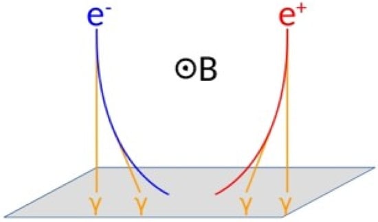
Figure 1.
The principle of charge-sign identification exploiting the simultaneous detection of the electron/positron and the synchrotron photons emitted during its motion within the geomagnetic field (B).
The idea of detecting synchrotron radiation for the measurement of cosmic rays was first proposed by Prilutskii in 1972 [9] and further developed by Stephens and Balasubrahmanyan in 1983 [10]. It has since been explored as a primary/complementary detection technique for several balloon-borne and satellite experiments (AMS [11], SRD [12], CREST [13], and Sonya [14]). The SRD and CREST collaborations have also tested a synchrotron radiation detector prototype in space [15,16]. Earlier efforts mainly aimed to use a synchrotron radiation detector as the primary instrument in order to indirectly measure the electron/positron energy. In contrast, EPSI focuses on developing an auxiliary detector dedicated to charge-sign discrimination. This auxiliary detector is designed to operate alongside a large-acceptance electromagnetic calorimeter capable of reaching the TeV region.
A notable recent example of this detection principle is the CREST balloon experiment, which operated for 10 days over Antarctica [16]. CREST attempted to measure the electron/positron flux by detecting only their synchrotron radiation using an X-ray detector. The campaign demonstrated the significant challenge posed by the astrophysical background when photon detection alone is employed. This is because the main trigger of the instrument relies on the coincidence of photons detected by the X-ray detector. EPSI overcomes this limitation by using the signal from the shower developing in the electromagnetic calorimeter to provide the main trigger of the instrument and by shielding the detector from the Sun to reduce the astrophysical background.
Another important difference between EPSI and the past projects is that the advances in scintillator technology, photon sensors, and coating materials now enable the construction of an X-ray detector array with better performance and at a reduced cost.
3. Synchrotron Radiation
In order to have an estimate of the relevant quantities involved in the charge-sign discrimination technique with EPSI, let us consider the simplified case shown in Figure 2. An electron of energy TeV travels in the x–z plane, perpendicular to the geomagnetic field, which is directed along the y axis and assumed to be uniform with intensity G. Under these assumptions, the helical trajectory reduces to a circular one and we can easily compute the main properties of synchrotron radiation. All of the following quantities are estimated for a 1 TeV electron, but everything can be easily extended to positrons. For this reason, in the remainder of this paper we use the term “electron” to refer interchangeably to an electron or a positron, except where it is explicitly specified.
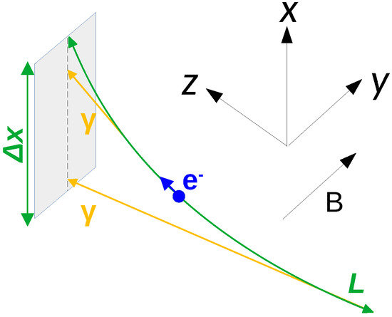
Figure 2.
Simplified geometry for the estimation of the quantities that are connected to synchrotron emission in space. Refer to the text for more details.
Let us place the detector in the x–y plane, with a longitudinal extension m along the x axis. In fact, this length corresponds to half of the instrument width, since the primary particle is required to hit near the calorimeter centre, as will be explained in Section 4. If p is the electron momentum, the curvature radius of the trajectory is given by:
which is much larger than . As a consequence, given the small entity of the magnetic deflection angle, the effective track length over which the synchrotron photons that reach the detector are emitted can be approximated as:
Since synchrotron radiation is emitted in a cone with an RMS opening angle of , the transverse dispersion of the photon impact point on the detector plane with respect to the electron bending plane can be roughly estimated as:
which means that photons are well aligned with the bending plane (see Figure 2). This is a very important feature to note, since it allows us to discriminate the synchrotron photons from random coincidences due to the astrophysical background, whose contribution will be described in Section 4.3. Indeed, with a detector segmentation of the order of 1 cm × 1 cm, it is possible to identify the synchrotron photons by simply checking if they are in temporal coincidence with the shower developed in the calorimeter and they lie on the electron-bending plane reconstructed by the calorimeter itself.
Following the theory on synchrotron emission described in ref. [17], the average number of photons, emitted by the electron, that reach the detector is estimated as:
while their characteristic energy is the so called critical energy:
The critical energy does not represent the average photon energy, but the energy that divides the synchrotron power spectrum into two halves of equal power. The power spectrum, which completely depends on this parameter, has a maximum for an energy of 0.29 . Therefore, most photons are emitted well below the critical energy.
As discussed after Equation (3), synchrotron photons lie on the electron-bending plane. In order to reduce coincidental X-ray hits from the astrophysical background, it is therefore necessary to require the detection of at least two aligned synchrotron photons to confidently measure the charge sign. On the other hand, Equations (4) and (5) clearly indicate that only a few synchrotron photons in the soft X-ray region reach the detector. As a consequence, this technique requires an instrument with a very high detection efficiency, of at least , in the 5–100 keV interval. These requirements are very strict and challenging, especially considering that the cost must be low enough to equip a large detection area in space.
It is not difficult to show that these two quantities scale as and . This means that charge-sign reconstruction is easier at larger energy values (e.g., and at TeV) and more difficult at lower energy (e.g., and at GeV). In particular, it is not applicable below a few hundreds of GeV where both photon yield and photon energies are too small. In that region, alternative approaches such as the geomagnetic East–West asymmetry can be exploited [2], provided that there is an energy interval where the two techniques overlap in order to allow for cross-validation.
4. Concept of the Space Instrument
A possible implementation of an instrument based on the EPSI idea is illustrated in Figure 3. The design combines a high-acceptance Electromagnetic CALorimeter (ECAL) with two large-area Synchrotron Radiation Detector (SRD) layers. This geometry has been obtained by fixing the mass of the ECAL to 2 t, since the SRD does not significantly impact on the mass budget. The design has then been chosen in order to maximize the geometric acceptance of the instrument by following simple considerations.
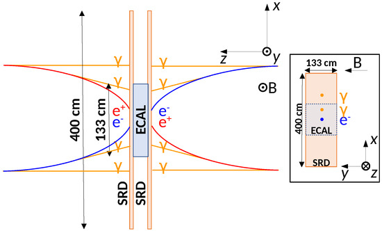
Figure 3.
Possible implementation of the EPSI space instrument, with the dimensions not to scale. The trajectories of electrons/positrons arriving from opposite directions, orthogonal to the geomagnetic field, and emitting synchrotron photons are also shown. For more details refer to the text.
As we can see, the main characteristic of the instrument is the capability to reconstruct the electrons impinging the two large faces of the ECAL from opposite directions equally well. The two SRD layers ensure charge-sign discrimination for both directions, thus doubling the acceptance without a significant increase of the payload mass. From a simple analytical estimation, this design reaches an effective geometric factor larger than a few above 1 TeV, necessary to extend the measurements to the TeV region.
The activities relative to the quantification of the performance, the optimization of the geometry, the estimation of the background, and the definition of the orbit are currently ongoing. We provide some details on the requirements and the implementation of the ECAL (Section 4.1) and the SRD (Section 4.2), we discuss the main sources of background for charge-sign reconstruction (Section 4.3) and electron identification (Section 4.4), and we make some considerations on the instrument orbit (Section 4.5).
Here, we describe a space instrument entirely developed for the stand-alone extension of the electron and positron measurements to the TeV region. Nevertheless, the EPSI idea can be applied on a current or future calorimeter-based experiment in a low Earth orbit to expand its physics reach. In such cases, it would be necessary to reconsider the geometry of the SRD according to the specific constraints of the mission. Although the achievable performance may be limited with respect to what is presented here, most of the discussion on the instrument in this section, as well as the detector development described in Section 5, remains valid.
4.1. The Electromagnetic CALorimeter (ECAL)
The ECAL is intended to reconstruct the energy and the trajectory of the incident electron, suppress the cosmic proton background and generate the main trigger of the instrument. The design of the calorimeter is not particularly challenging, since similar devices are now commonly used in space. In particular, based on the results from the CaloCube collaboration [18,19,20], the ECAL can be made of CsI:Tl cubic crystals readout by photodiodes. The geometry is fixed by requiring a depth of 25 cm (), which is enough to obtain an energy resolution of about 5% exploiting the fit on the longitudinal shower profile, as done in the Fermi-LAT experiment [21]. Thus, with a mass of 2 t, we find that the two square faces have an area of 1.33 m × 1.33 m, which ensures an acceptance that is large enough to reach the TeV region. To give an idea on the ECAL segmentation, the single crystal can be chosen with a depth of the order of 2 cm and an area of 3.5 cm × 3.5 cm (equivalent to one Moliere radius) or larger. The first requirement is necessary to have enough points to perform the fit on the longitudinal shower profile, hence leading to a good energy resolution. The second one ensures an angular resolution better than a few degrees [22], which is important to reconstruct the electron-bending plane used to separate the synchrotron photons from the astrophysical background.
4.2. The Synchrotron Radiation Detector (SRD)
The SRD is intended to detect the synchrotron photons emitted by the incident particle to allow for electron/positron discrimination. Each of the two layers is the same size as the ECAL along the y axis, but it is larger along the x axis so that it can enhance the detection of synchrotron photons, which lie on the electron-bending plane. Here we suggest an area of 4 m × 1.33 m, but further considerations on power and mass budget may affect this number. As described in Section 3, the property of synchrotron emission by electrons in the geomagnetic field leads to the following requirements for the single detection cell:
- High detection efficiency: the SRD must achieve a detection efficiency of at least in the 5–100 keV range, to ensure the detection of at least two synchrotron photons aligned with the electron-bending plane, necessary for charge-sign discrimination;
- Low energy coverage: expanding the operating range below 5 keV, ideally down to 1 keV, is important to extend charge-sign identification to electrons of a few hundreds of GeV, increasing the overlap with the geomagnetic East–West asymmetry technique;
- Fine spatial segmentation: a granularity of the order of 1 cm × 1 cm is necessary to separate synchrotron photons from diffuse astrophysical X-ray background, by exploiting their narrow dispersion with respect to the bending plane;
- Fast time signal: a signal duration of a few microseconds or, even better, a few hundreds of nanoseconds is important to further suppress the random coincidences from astrophysical background associated with an electron trigger;
- Large area scalability: given the large area of the SRD, the single cell must be cheap enough to allow for the construction of a large array at a reduced cost and compliant with space applications, especially considering power consumption and detector mass.
It is important to note that for our application the energy resolution of the single detection cell is not a key feature: all is needed is simply to know if in a given cell there is a photon hit or not. However, the ability to measure the photon energy is helpful if we want to reconstruct the electron energy from the multiplicity and energy distributions of the detected synchrotron photons. From ref. [11], we expect an SRD electron energy resolution of about 30%, mainly driven by the property of synchrotron emission, rather than by the photon energy resolution of the single cell. Even if this number is much larger than the one obtained with the ECAL, this independent information on the electron energy is very useful to cross-check the absolute energy scale, which is one of the main uncertainties in space experiments based on a calorimeter [23].
4.3. Background for Charge-Sign Reconstruction
Since charge-sign identification relies on the simultaneous detection of the synchrotron photons that can be associated to the electron-bending plane, any signal that can mimic a photon hit on one of the SRD cells contributes to the background. We identify three different sources of background: astrophysical X-rays, charged cosmic rays, and calorimeter backscattering.
The main contribution to the astrophysical X-ray background is the Sun, which is the brightest X-ray source by a factor of about 1 million [24]. As it was confirmed during the test flight of the SRD collaboration [15], any space detector aiming to measure the synchrotron photons emitted by electrons cannot operate when exposed to the Sun. This requires particular attention to the design of the payload and the definition of the orbit, as described in Section 4.5. Regarding the extrasolar X-ray background, the dominant contributions are from the cosmic X-ray background [25] and bright galactic sources [26], whereas the galactic ridge diffuse emission [27,28] and Earth’s -ray albedo [29]. For completeness, it should be noted here that the -ray albedo, due to the interactions of cosmic rays in the Earth’s atmosphere, is not of astrophysical origin, unlike the others already mentioned. Nonetheless, it has been included in this group, since it effectively contributes to the detector X-ray background, even if it has only a marginal impact. Preliminary estimates of the extrasolar X-ray background were obtained by considering all the four components, assuming a detector in low Earth orbit (LEO) at an altitude of approximately 500 km. For this altitude, independently of the orbital inclination, we estimated an upper limit of about ph/s on the whole SRD, or about 600 ph/s on a single cell, in the 1–100 keV range. The background from higher energy X-rays can be neglected because of both the lower flux above a few tens of keV and the lower detection efficiency above approximately 100 keV. Indeed, given the 2.5 mm thick CsI:Tl crystal described in Section 5, detection efficiency rapidly decreases from about 90% at 100 keV to 15% at 300 keV and 5% at 1 MeV [30]. Considering an integration window of 1 µs after each electron trigger, our preliminary estimates translate into about 10 background X-ray hits on the whole surface of each of the two SRD layers. This background rate can be easily rejected by exploiting the fact that the signal X-rays lie on the electron bending plane, as described in Section 3.
Low-energy cosmic rays can generate spurious hits in the SRD. Actually, this is not a problem for background itself since the minimum energy deposited by cosmic rays is much larger than the maximum signal useful for synchrotron photons. To have an idea, considering the possible implementation described in Section 5, the lowest signal by a cosmic ray is from vertical minimum ionizing protons, with an average of 1.4 MeV, whereas photon detection efficiency significantly drops above a few hundreds of keV. Therefore, by properly optimizing the dynamic range for the final space application, cosmic rays will always saturate the read-out electronics. On the other hand, it is important to check that the rate of cosmic rays is sufficiently low to avoid a large amount of unusable saturated channels in coincidence with an electron trigger. Considering only the proton contribution measured in ref. [31] and the solar modulation potential modelled in ref. [32], we expect a maximum of about above 1 GeV at the magnetic pole, and much less at lower latitudes. Given the planar geometric factor of the SRD and assuming an integration window of 1 µs in the single cell, it is easy to see that for each triggered electron the probability to have an SRD cell hit by a cosmic ray is negligible.
The last contribution to the background is due to the backscatter component from the high energy shower that develops in the ECAL. In electromagnetic showers, backscattered particles are mostly photons below a few MeV, which mainly interact with the upstream detectors via Compton scattering. When we have an electron trigger, it is therefore possible that backscattered photons generate spurious hits in the SRD. At present, there is a very limited knowledge about backscattering, in terms of the type of particles, the energy distribution, the angular dependence, and the arrival time. From the study carried out by the FERMI-LAT collaboration [33], it is clear that backscattering decreases as we move away from the electron track and approximately increases as the square root of the electron energy. However, the impact of this background cannot be modelled in a simple way, since it requires a complete simulation of the electromagnetic shower developing in the EPSI space instrument. In addition, due to the significant model dependence of backscattering, different interaction models must be tested to quantify the uncertainty on the impact of this background. If the backscattering contribution proves to be significant, several solutions are available to mitigate its effect. Backscattering hits can be identified using estimators based on the energy release in the single cell, the position with respect to the electron track and the arrival time with respect to the electron trigger. This task is currently under study and will be reported in a future publication.
4.4. Background for Electron Identification
In space experiments based on a calorimeter, the main challenge for the measurement of the electron component is the contamination from the much more abundant proton population. This is generally performed by exploiting the intrinsic differences between the electromagnetic and hadronic showers, but a deep finely-segmented calorimeter is necessary to reach a good rejection factor at high energies. A natural advantage of the EPSI approach is that protons and nuclei can be effectively separated from electrons and positrons. Let us consider again Equations (4) and (5) for a nucleus with charge Z and mass M: it is easy to show that and . To give an idea, this means that a 1 PeV proton leads to and , i.e., a negligible amount of photons reaching the SRD and in an energy range to which it is insensitive. As a consequence, the presence/absence of the associated synchrotron photons is enough to perform electron/proton discrimination.
4.5. Instrument Orbit
The choice of the instrument orbit is particularly challenging for a payload based on the EPSI idea. Two aspects have a large impact on this decision: the Earth magnetic field and the Sun X-ray background. They are briefly discussed in the following.
From Equations (4) and (5), it is clear that and . This means that charge-sign identification is enhanced when the payload orbit mainly crosses regions of high magnetic field, as this increases the number of synchrotron photons reaching the detector and shifts their energy into a range where detection efficiency is larger. On the other side, as we can see from Figure 2, this technique effectively works only if the long side of the SRD is perpendicular to the geomagnetic field: otherwise, the intersection of the bending plane with the detector is reduced, as well as the number of detectable synchrotron photons. Although the detection technique can operate outside this ideal configuration, maximizing the effective geometric factor requires not only an appropriate selection of the satellite orbit, but also a continuous control of its attitude along the orbit. The accuracy requirements and potential solutions for the attitude control system, such as magnetorquers and reaction wheels, will be addressed in future studies.
As discussed in Section 4.3, solar X-rays represent the major background of this technique and the instrument cannot operate when directly exposed to the Sun. A possible solution is to operate the payload edge-on to the Sun, in such a way that solar X-rays see the thin depth of the SRD, eventually being absorbed in the outer row of active cells of the array. An even better solution is to employ a passive shield on the four lateral sides, in order to completely protect the SRD from the incoming solar X-rays.
Considering these two aspects, a Sun-synchronous orbit could be a good choice for an instrument based on the EPSI idea. This solution will be investigated in the future by means of more detailed considerations and a realistic simulation of the orbit.
For completeness, it is worth noting that other important factors to consider are the radiation damage of the sensor and the impact of micrometeoroids. The radiation damage of the sensor can be significant depending on the instrument orbit. At the moment, a quantitative assessment of this effect lies beyond the scope of this paper. Nonetheless, it will be addressed in future studies through dedicated measurements of the radiation hardness of the sensor and the evaluation of the radiation dose for specific orbital configurations. The rate of micrometeoroid impacts is not trivial to estimate, considering that objects from 1 mm to 1 cm in size make up most of the space debris population and are very hard or impossible to track from Earth. Nevertheless, an upper limit can be provided considering a satellite in LEO at an altitude of 500 km and with inclination of ∼80°, which is the orbital inclination where the highest number of collisions is expected. Using the data from ref. [34] and adjusting for the undetectable debris by multiplying by a factor of one hundred as indicated by ESA [35], we expect a rate of 1.6 hits yr−1 on the whole SRD. Therefore, even if the materials exposed to the space environment can be fragile and can be damaged by micrometeoroids, the impact rate is low enough not to affect the SRD performance.
5. Design of the Detection Cell
Following the requirements given in Section 4.2, semiconductor detectors are not good candidates for the EPSI idea, both because their limited thickness constrains the range where the detection efficiency is suitable to below a few tens of keV, and because they are quite expensive to equip the large area needed for this application. A better and cheaper baseline for the single cell consists of a thin scintillator crystal optically coupled to a silicon photomultiplier (SiPM) and wrapped in a reflective layer, with a thin X-ray entrance window. As shown in Figure 4, the crystal has a square surface and the SiPM is glued at the centre of the face that is opposite to the one below the entrance window. In the following, we briefly discuss with more details each component of the cell.
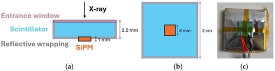
Figure 4.
A schematic representation of the baseline SRD cell from a side view (a) and from the SiPM side (b): a thin scintillator crystal (light blue), wrapped in a reflective material (grey), with a thin X-ray entrance window (pink) on a face, and a SiPM (orange) glued at the centre of the opposite one; in the representations, the wrappings on the shown sides of the cell are omitted. Image of the current configuration seen from the SiPM side (c).
A high detection efficiency in the soft X-ray region requires scintillators with a very large light yield. A good candidate is CsI:Tl, which is a relatively cheap and commonly used scintillator with a light yield of approximately 54 ph/keV. Its main drawback, however, is the relatively long decay constant, higher than ∼700 ns [36]. A better solution is offered by the GAGG:Ce crystal, which has an even larger light yield of ∼60 ph/keV and a much smaller decay constant of ∼150 ns, which helps to reduce the impact of astrophysical background on charge-sign reconstruction. GAGG:Ce is a relatively new material and it is quite expensive at the moment. For this reason, we decided to start the optimization of the detection unit using CsI:Tl, eventually replacing it with GAGG:Ce in future laboratory tests.
In order to maximize the number of detected scintillation photons, the SiPM must have a large active area and a high photon detection efficiency (PDE), while keeping the dark-count rate (DCR) to a reasonably low value. Among the different photon sensors that have been tested, we chose the Hamamatsu MPPC S13360-6075PE. The SiPM consists of 6400 cells (75 m pitch) covering a photosensitive area of 6 × 6 mm2 and well matches our requirements, featuring a fill factor of 82%, a DCR of ∼2 MHz, and a PDE of ∼40% at the emission peak of both scintillators. As described in Section 6.1, the single cell characterization described in this paper has been performed with a simple system based on a digitizer and post-processing of the acquired waveform. The selection of the read-out electronics necessary for a large amount of channels is beyond the scope of this work.
The most challenging task is the choice of the entrance window material. The Enhanced Specular Reflector (ESR), a polymeric foil with a thickness of ∼65 µm and a reflectivity ∼98%, is a good candidate to maximize the light collection efficiency. While this film provides a promising solution for the wrapping material, it is too thick to be used for the entrance window, since the X-rays below a few keV would be absorbed inside it. The results discussed in this paper were obtained by completely wrapping the crystal with ESR. As discussed in Section 6.3, this is enough to ensure a good detection efficiency above 5 keV, but a different solution is needed to maximize the transmission down to 1 keV while maintaining a large light collection efficiency of the scintillation photons and still shielding from optical and ultraviolet background. Entrance windows based on thin Al depositions and aluminized Mylar foils are currently under study. Even if these materials are very fragile and can be damaged by micrometeoroids, the impact rate is low enough to not affect the SRD performance. A thin Al layer of the order of hundreds of nm can be deposited using a sputtering machine, and we successfully realized a few prototypes in our laboratory. The properties of the deposition were investigated using ion-beam analysis techniques at the LABEC facility [37]: the thickness was compatible with the expected one and no significant contamination was found in the Al layer. However, when we characterized the cell response to incident X-rays, we found that the reflectivity—and consequently the light-collection efficiency—was much smaller than what we had expected from the literature. We interpreted this signal loss as being due to the roughness of the crystal surface, which significantly degrades the optical properties of the deposition. Realizing the entrance window using Al deposition would require to process the crystal in order to reduce its surface roughness to the nm scale, which is not only difficult, but also expensive. A thin aluminized Mylar foil with a thickness of ∼2 µm is a cheaper and simpler solution that also leads to a larger reflectivity. This option has been tested by wrapping a crystal with ESR on all faces except from the entrance one, where aluminized Mylar was used instead. The results indicate a drop in light-collection efficiency of ∼50% with respect to the value obtained with the crystal fully wrapped with ESR. The number is compatible with the same behaviour that we observe with optical-ray tracing simulations when we change the reflectivity of the entrance window from 98% (ESR) to 92% (Al). Even if this reduction in light-collection efficiency seems significant, we can compensate it by increasing the overvoltage of the SiPM and by cooling the system in order to reduce the dark-count contribution, as discussed in Section 7.
Another key aspect of this study is the size of the detection cell. The area of the detection cell was chosen to be 2 cm × 2 cm, as a compromise between a reasonable number of readout channels for the space instrument and the segmentation needed to identify the charge sign, as described in Section 4.2. Once the choices of crystal, sensor, wrapping material, and cell area size were set, the optimal thickness was studied using optical-ray tracing simulations, as shown in Figure 5. For this purpose, we evaluated how this parameter affects the mean number of collected photons. The result indicates that a thickness of 3 mm maximizes light collection as a compromise between self-absorption losses, dominant for thick crystals, and transmission losses, dominant for thin ones. For the studies reported in this paper, we decided to use 2.5 mm thick crystals, as they were readily available and the light collection is less than a few percent below the optimal value. Finally, again using optical-ray tracing simulations, we noted that light collection drops when increasing the surface roughness of the crystal, motivating the adoption of polished surfaces.
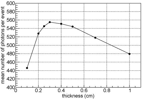
Figure 5.
Mean number of collected photons per event as a function of the crystal thickness for a CsI:Tl crystal with a fixed area of 2 cm × 2 cm, completely wrapped in ESR, and coupled to MPPC S13360-6075PE. The result is obtained from the simulation of radioactive source, with the dominant X-ray lines reported in Section 6.3. The FLUKA [38] simulation package with optical-ray tracing option was used for this purpose.
6. Laboratory Characterization
In this section, we report the main results relative to the performance of the current version of the single cell of the SRD. The main goal is to quantify the X-ray detection efficiency, which is the quantity that we want to maximize in this phase of the detector design. The prototype that has been tested consists of a CsI:Tl crystal with size 2 cm × 2 cm × 2.5 mm, coupled to a S13360-6075PE MPPC and completely wrapped in ESR. Here we remark that these results are still preliminary and, as discussed in Section 5, the detection threshold can be extended down to 1 keV at the cost of a reduction in the light collection efficiency.
This section is divided as follows. After a short description of the experimental setup (Section 6.1), we discuss the procedure used to calibrate the response of the detector by means of the SiPM dark-count distribution (Section 6.2), and we present the performance in terms of linearity, resolution, and efficiency estimated using radioactive sources (Section 6.3).
6.1. Experimental Setup
The laboratory characterization of the response of the single cell has been carried out with the simple system sketched in Figure 6. The SiPM is connected to a non-inverter operational amplifier with gain of about 25. After amplification, the analog signal is transmitted to the CAEN DT5790 Digitizer (CAEN S.p.A., Viareggio, Italy), which is connected to the acquisition PC via USB. For each event, we acquired the digitized waveform starting from 100 ns before the trigger time, in order to have enough data points to accurately estimate the baseline. To minimize the electronic noise and the optical background, the detector, together with the amplifier, is placed inside a shielded aluminium box. Inside this box, we realized a plastic support to house the prototype and to support a radioactive source at a fixed distance of about 6 cm from it. For simplicity, we did not operate in vacuum conditions, since in this setup the air absorption is about 25% at 5 keV and negligible above 20 keV. Temperature was continuously monitored and the SiPM bias voltage was corrected for the temperature-dependent coefficient as indicated by the supplier.
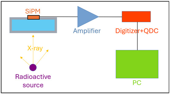
Figure 6.
Schematic view of the experimental setup, with the detector cell irradiated by an X-ray source. The signal collected by the SiPM is amplified and digitized before being acquired by the PC. Refer to the text for the details.
As explained in Section 6.2 and Section 6.3, light-collection efficiency is the key parameter that we use to characterize the performance of the single cell. The experimental setup allows us to measure this quantity by (1) acquiring dark-count events to calibrate the response, by estimating the conversion factor from ADC values into m.c.o. (micro cells on) units and (2) acquiring X-ray events from different radioactive sources, in order to quantify the response as a function of the energy. Given the very different amplitude and duration of the input signal, we adopted different run configuration parameters for the two cases, in particular changing the trigger threshold and the time window.
Online and offline event selections have been applied. For dark-count acquisitions, we properly set the digitizer internal threshold to reject the abundant pile-up events. For radioactive source acquisitions, given the low activity of the available sources and the relatively small solid angle, pile-up was not a problem, and dead time was within a few percent of the acquisition time. A significant inefficiency of about 15% was due to a post-processing filter, applied to remove events where we had large fluctuations in the points at the beginning of the waveform, which are used for the estimation of the baseline. All inefficiencies have been taken into account in the analysis by properly rescaling the spectra for an energy-independent correction factor.
For each event, the signal was extracted from the waveform by considering its area, i.e., integrating it for a sufficient amount of time. The same procedure was applied both for radioactive source and dark-count runs, but selecting very different time window in the two cases. The reason for this choice was motivated by two different considerations. First, scintillation photons are emitted over a long time with respect to the response of the single cell of the SiPM. Second, we want to be able to express the X-ray deposit in terms of m.c.o. in order to quantify the photon detection efficiency. Taken together, these two aspects show that the signal must be extracted from the waveform area, rather than from its amplitude.
6.2. Detector Calibration
The detector calibration was done with dark-count events acquired in the absence of radioactive sources. After applying the cuts described in Section 6.1, we obtained a distribution as the one shown in Figure 7. Here the signal is expressed in ADC units and can be converted in the equivalent number of m.c.o. by fitting the first two peaks with a double Gaussian function. The fit parameters are the position of the first peak (), the distance between the peaks (), a standard deviation common to both peaks (), and an amplitude parameter for each of them (A). This simplified approach is possible because, given the large gain of the SiPM, the electronic noise dominates over the charge fluctuations and we can assume the same for both peaks. The and parameters were used as the coefficients of the linear calibration equation between the signal expressed in ADC counts, , and in m.c.o. number, , that is:
The uncertainty on the calibration procedure was estimated by studying the dependence on the fit range, since the statistical contribution provided by the fit was negligible. By conducting multiple fits in different ranges, this calibration uncertainty was estimated to be on the signal expressed in terms of the m.c.o. number.
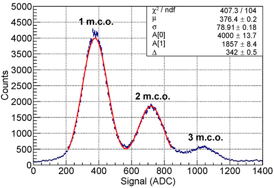
Figure 7.
Distribution of dark-count signals expressed in ADC units, with superimposed double Gaussian fit: the fit parameters are used to convert from ADC units to m.c.o. number.
The dark-count distribution was also used to estimate the cross-talk probability among the SiPM cells. This was carried out considering the ratio between the number of counts above 1.5 m.c.o.—assumed as cross-talk events—and the ones above 0.5 m.c.o.—to account for electronic noise. It should be noted that, given the long 600 ns integration window, our definition of cross-talk includes not only the prompt contribution, but the delayed contribution and afterpulses as well. Consequently, the estimated cross-talk probability is higher than the prompt contribution indicated in the data-sheet, remaining consistently at approximately 55% over multiple acquisitions.
6.3. Prototype Results
Three radioactive isotope sources were used to test the prototype detector: , , and . The corresponding measured spectra are shown in Figure 8 and their main emission lines are listed in Table 1.
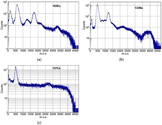
Figure 8.
Measured spectra, calibrated in m.c.o. units, of the (a), (b) and (c) sources. Structures corresponding to the emission lines of the sources and to Compton backscattering peaks are clearly visible. The main emission lines are reported in Table 1.

Table 1.
The main photon emission lines from each radioactive source used in our study [39]. For multiple lines that are too close to be separately resolved with our detector, the energy corresponds to the weighted mean obtained by taking into account each line yield.
Considering all these three sources, eleven structures corresponding to known emission lines were identified. By means of a fitting procedure, the central value, the standard deviation and the intensity of the peaks have been obtained for each of these structures. Each full-energy peak was assumed to follow a Gaussian distribution, whereas a first-order polynomial was used to model the Compton background below the peak. The main uncertainty on fit parameters comes from uncontrolled changes in experimental conditions (e.g., slight source misalignment). By repeating acquisitions of the same source spectrum, we estimated this reproducibility error to be ∼1.5%. An example of this fitting procedure is shown in Figure 9 for the gamma emission peak around 120 keV of the source.
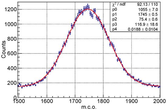
Figure 9.
An example of the Gaussian fit to the gamma emission peak around 120 keV of the source. The Gaussian function is overlapped to a linear function to take into account the Compton background. In this case, the Gaussian mean and standard deviation correspond to 1745 and 75 m.c.o., respectively.
Figure 10 shows the detector signal, expressed in m.c.o. and normalized to the peak energy, as a function of the peak energy itself. The errors reported are the quadratic sum of statistical and systematic errors, and include the 1.5% calibration error discussed in Section 6.2 and the 1.5% reproducibility error discussed above.
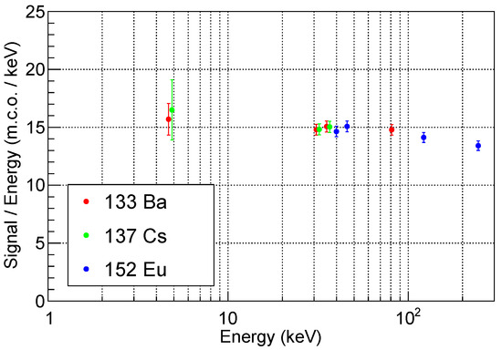
Figure 10.
Detector signal, expressed in m.c.o. and normalized to the peak energy, as a function of the peak energy for the eleven structure considered in the analysis.
The response exhibits a slightly non-linear behaviour, which is clearly visible in the two points above 100 keV. This effect probably arises from the intrinsic non-proportionality of the scintillator light yield [40]. Since the precise energy measurement is not the primary purpose of our detector, the response can be approximated as linear within the energy range of interest, with a proportionality factor of about 15 m.c.o./keV. If we correct this result for the 55% total cross talk discussed in Section 6.2, the number of detected scintillation photons per unit of X-ray energy deposit is about 9.7 ph/keV. Given the CsI:Tl light yield and decay constant described in Section 5, we expect to collect ∼85% of the total number of scintillation photons in the integration window that we have selected. Our measurement shows that the scintillation light detection efficiency, defined as the fraction of the scintillation photons generated by the X-ray interaction that gives a signal in the SiPM, is ∼21%. Finally, correcting for the PDE of the SiPM at the CsI:Tl emission peak mentioned in Section 5, the light collection efficiency, i.e., the fraction of the scintillation photons generated by the X-rays that impact on the SiPM, is about 53%.
Figure 11 shows the energy resolution, defined as the ratio between the standard deviation and the central value, as a function of the peak energy. The errors reported are the quadratic sum of statistical and systematic errors, as described above.
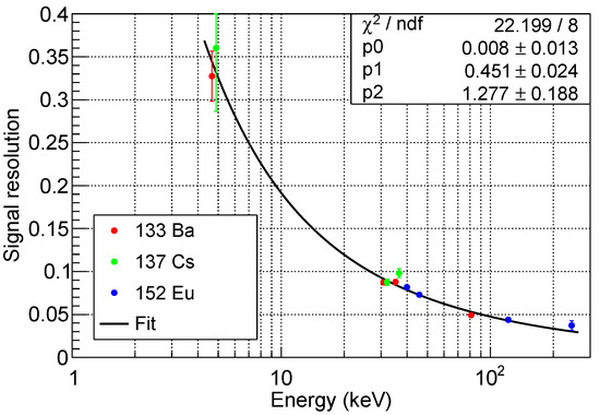
Figure 11.
Signal resolution as a function of the peak energy. The data points are fitted using the function described by Equation (7), which takes into account the contributions from non-uniformity and non-proportionality (), statistical fluctuation (), and electronic noise ().
The fit on the data points has been performed using Formula (5.59) from ref. [41], that is
where accounts for the electronic noise, for statistical fluctuations, and the constant term for non-proportional scintillator response and non-uniform light collection efficiency, due to the variation of this quantity over the whole area. As expected, the electronic noise is the dominant factor at low energy, because of the event-by-event fluctuations of the dark-count contribution. At high energies, where statistical fluctuations are negligible, resolution is limited by the irreducible constant term associated to non-proportionality and non-uniformity.
For each peak identified in the spectra, the measured peak intensity has been compared to the number of counts expected from the activity of the radioactive sources, after including all the various contributions of the emission lines, and correcting for the solid angle coverage of the detector. The ratio between the measured peak intensity and the expected number of counts was called photoelectric efficiency, to indicate that we are considering only the events where a photoelectric interaction occurred and the resulting electron deposited all its energy inside the crystal, thus producing what is generally referred to as the full energy peak. One or more Compton scattering may take place inside the crystal before the final photoelectric interaction. However, the events where the secondary photons generated by Compton scattering escape the detector, or where the secondary electrons produced by the photoelectric effect leave the crystal before releasing all their energy, do not contribute to the full energy peak. If the electronic noise is small enough, these events are detected by the system, thus contributing to the detection efficiency, but not the photoelectric one. As a consequence, photoelectric efficiency is a quantity that is easy to measure, but it slightly underestimates the real detection capability of our system. For this reason, in order to have a better interpretation of the experimental results, a simulation was performed and the result is shown in Figure 12, together with the data points. The errors reported here are the quadratic sum of statistical and systematic uncertainties. With respect to the contributions previously discussed, we added a 3% uncertainty on the activity of the radioactive sources, and a 0.6% uncertainty on the solid angle coverage.
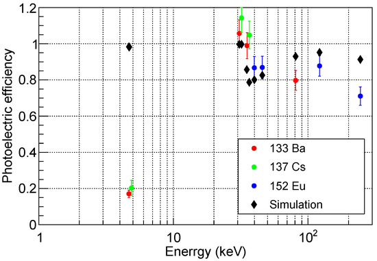
Figure 12.
Photoelectric efficiency as a function of the peak energy. Simulation expectations are shown as black points. See text for a detailed definition of this quantity.
Around 5 keV the measured efficiency is very low compared to the simulation. This can be attributed to self-absorption in the radioactive source and absorption in the air between the source and the detector, since both effects are not taken into account in the simulation. At higher energies, the simulations are compatible with the experimental measurements. In particular, in both cases we observe a jump in the photoelectric efficiency between 30 keV and 40 keV, an energy region which corresponds to an edge in the photoelectric cross-section of the CsI [30]. Overall, the efficiency is larger than 80%, with a maximum value of approximately 100% at about 30 keV. Therefore, we can conclude that our prototype satisfies the basic requirements described in Section 4.2 down to 5 keV.
7. Ongoing and Future Work
The study presented in this paper focused on CsI:Tl, which is cheap and well-known compared to GAGG:Ce. Preliminary measurements indicate that GAGG:Ce is a promising candidate due to its fast response and high light yield. Its greater robustness compared to CsI:Tl also helps in its handling, and its chemical and physical properties are more suited for the deposition of a highly-reflective Al layer. On the other side, non-proportionality is quite strong at low energies and the signal loss could be significant [42]. Consequently, upcoming efforts will focus on completing the GAGG:Ce characterization and comparing its performance to CsI:Tl in terms of efficiency and timing.
The single detection unit made of CsI:Tl scintillator satisfies our basic requirements. In order to extend charge-sign discrimination to electrons of about 100 GeV, it would be important to further lower the X-ray detection threshold down to 1 keV. For this purpose, future activities will be dedicated to the optimization of both the entrance window and signal resolution, which we briefly discuss in the following.
Regarding the entrance window, current efforts focus on optimizing alternative materials to replace ESR in order to balance optical reflectivity and X-ray transmission. As discussed in Section 5, we considered thin sputtered aluminium layers and micrometric aluminized Mylar foils as possible solutions. Both alternatives showed extremely low optical photon transmission, even below the per-mil level, which is a highly desirable feature for suppressing the background from optical photons in space. At the same time, preliminary measurements revealed a drop in light collection efficiency in both cases. For thin Al depositions, this effect is larger than expected, indicating that this is not a viable solution unless the crystal surface is worked on at the nm scale. For aluminized Mylar foils, the signal loss is about 50%, in good agreement with optical simulations, and a valid solution for our application.
In parallel, signal resolution optimization is being pursued by reducing the contribution of the noise term in Equation (7), which is the dominant one at low energies and is mainly due to the dark-count contribution. Tests in a climatic chamber have shown that operating the SiPM at low temperatures significantly improves the signal resolution by reducing the impact of noise. With a proper spacecraft thermal control system and shielding from the Sun, a sensor cooling system might not be required in the final instrument design. However, it plays a crucial role in our laboratory setup, ensuring performance close to ideal in-orbit conditions. For this reason, we are currently working on the development of a Peltier cooling system in order to characterize the detector response at low temperatures.
Once these activities have been completed, the performance of the single detection unit will be accurately measured down to 1 keV. This will be carried out with a beam test at LABEC facility [37], exploiting the quasi-monochromatic X-rays emitted by monoelemental high-purity targets excited by a low-energy proton beam [43]. After the confirmation that the performance well matches our requirements, we will start the construction of a small prototype, comprising about 20 cells. This task will require the development of a dedicated mechanical support structure and a readout system capable of handling multiple channels. The prototype will be characterized in laboratory and later at an electron-beam test facility, in order to get the final proof-of-concept of the EPSI idea.
In parallel to this hardware activity, a detailed simulation of the geometry of the space instrument will be developed. For this task, we will take into account the response of the single detection unit that has been experimentally observed. After the implementation of the reconstruction algorithm, the expected performance of the space instrument will be quantified. Particular focus will be devoted to energy resolution, angular resolution, charge-sign discrimination capability, and X-ray background suppression. Connected to this activity, a dedicated study to investigate the optimal payload orbit will be carried out. Finally, we will define the main details of an instrument based on the EPSI approach: this could be implemented in the future either as a stand-alone experiment or as an auxiliary instrument on a previously planned space mission.
8. Conclusions
The EPSI project is a two-year R&D, financed as PRIN (Progetto di Rilevante Interesse Nazionale) with EU recovery funds. It aims to develop a novel charge-sign discrimination technique that can be used in space as an auxiliary detector in calorimeter-based cosmic-ray experiments. In this paper, we described the general idea, the concept of the space instrument, and the design of the detection unit. The laboratory results obtained so far match our requirements well, with a detection efficiency larger than 80% above a few keV. Preliminary tests indicate that there is margin for further extension of the energy range down to 1 keV. A detailed simulation of the space instrument is ongoing, in order to verify the expected performance and to quantify the background impact. These studies will be reported in future works.
Author Contributions
Conceptualization, P.P.; methodology, O.A., E.B., A.C., R.D., G.D.G., P.P. and C.V.; software, E.B., G.D.G. and P.P.; validation, E.B., A.C., G.D.G., P.P. and C.V.; formal analysis, G.D.G. and P.P.; investigation, P.B., M.C., G.D.G., L.F., O.S., A.V. and C.V.; resources, E.B. and A.C.; data curation, E.B. and G.D.G.; writing—original draft preparation, E.B., G.D.G., P.P. and C.V.; writing—review and editing, L.B., P.B., M.B., M.C., N.F., E.G. and A.P.; visualization, C.V.; supervision, E.B. and A.C.; project administration, E.B. and A.C.; funding acquisition, E.B. and L.P. All authors have read and agreed to the published version of the manuscript.
Funding
This research (PRIN 2022C5PHBB-PNRR M4.C2.1.1-CUP I53D23000650006) is financed using European Union recovery funds “Next Generation EU”. This work was also supported by the Italian Space Agency (ASI) under the “Space it Up!” project (CUP I53D24000060005).
Data Availability Statement
The datasets presented in this article are not readily available because data access is restricted to the members of the EPSI collaboration. Requests to access the datasets should be directed to the authors.
Conflicts of Interest
The authors declare no conflicts of interest.
References
- Adriani, O.; Barbarino, G.C.; Bazilevskaya, G.A.; Bellotti, R.; Boezio, M.; Bogomolov, E.A.; Bonechi, L.; Bongi, M.; Bonvicini, V.; Bottai, S.; et al. An anomalous positron abundance in cosmic rays with energies 1.5–100 GeV. Nature 2009, 458, 607–609. [Google Scholar] [CrossRef] [PubMed]
- Ackermann, M.; Ajello, M.; Allafort, A.; Atwood, W.B.; Baldini, L.; Barbiellini, G.; Bastieri, D.; Bechtol, K.; Bellazzini, R.; Fermi LAT Collaboration. Measurement of separate cosmic-ray electron and positron spectra with the Fermi Large Area Telescope. Phys. Rev. Lett. 2012, 108, 011103. [Google Scholar] [CrossRef] [PubMed]
- Aguilar, M.; Cavasonza, L.A.; Ambrosi, G.; Arruda, L.; Attig, N.; Azzarello, P.; Bachlechner, A.; Barao, F.; Barrau, A.; AMS Collaboration. Towards Understanding the Origin of Cosmic-Ray Positrons. Phys. Rev. Lett. 2019, 122, 041102. [Google Scholar] [CrossRef] [PubMed]
- Gabici, S.; Evoli, C.; Gaggero, D.; Lipari, P.; Mertsch, P.; Orlando, E.; Strong, A.; Vittino, A. The origin of Galactic cosmic rays: Challenges to the standard paradigm. Int. J. Mod. Phys. D 2019, 28, 1930022. [Google Scholar] [CrossRef]
- DAMPE Collaboration. Direct detection of a break in the teraelectronvolt cosmic-ray spectrum of electrons and positrons. Nature 2017, 552, 63–66. [Google Scholar] [CrossRef]
- Adriani, O.; Akaike, Y.; Asano, K.; Asaoka, Y.; Berti, E.; Bigongiari, G.; Binns, W.R.; Bongi, M.; Brogi, P.; CALET Collaboration. Direct Measurement of the Spectral Structure of Cosmic-Ray Electrons+Positrons in the TeV Region with CALET on the International Space Station. Phys. Rev. Lett. 2023, 131, 191001. [Google Scholar] [CrossRef]
- Adriani, O.; Altomare, C.; Ambrosi, G.; Azzarello, P.; Barbato, F.C.T.; Battiston, R.; Baudouy, B.; Bergmann, B.; Berti, E.; Bertucci, B.; et al. Design of an Antimatter Large Acceptance Detector In Orbit (ALADInO). Instruments 2022, 6, 19. [Google Scholar] [CrossRef]
- Schael, S.; Atanasyan, A.; Berdugo, J.; Bretz, T.; Czupalla, M.; Dachwald, B.; von Doetinchem, P.; Duranti, M.; Gast, H.; Karpinski, W.; et al. AMS-100: The next generation magnetic spectrometer in space—An international science platform for physics and astrophysics at Lagrange point 2. Nucl. Instrum. Meth. A 2019, 944, 162561. [Google Scholar] [CrossRef]
- Prilutskij, O. The possibility of registering primary cosmic electrons by means of synchrotron radiation in the geomagnetic field. Sov. J. Exp. Theor. Phys. Lett. 1972, 16, 320–321. [Google Scholar]
- Stephens, S.; Balasubrahmanyan, V. Earth’s magnetic field as a radiator to detect cosmic ray electrons of energy >1012 eV. J. Geophys. Res. Space Phys. 1983, 88, 7811–7822. [Google Scholar] [CrossRef]
- Hofer, H.; Pohl, M. Charge determination of high-energy electrons and nuclei by synchrotron radiation with AMS. Nucl. Instruments Methods Phys. Res. Sect. A Accel. Spectrometers Detect. Assoc. Equip. 1998, 416, 59–63. [Google Scholar] [CrossRef]
- Anderhub, H.; Bates, J.; Bätzner, D.; Baumgartner, S.; Biland, A.; Camps, C.; Capell, M.; Commichau, V.; Djambazov, L.; Fanchiang, Y.J.; et al. Design and construction of the prototype synchrotron radiation detector. Nucl. Instruments Methods Phys. Res. Sect. A Accel. Spectrometers Detect. Assoc. Equip. 2002, 491, 98–112. [Google Scholar] [CrossRef]
- Yagi, A.; Bower, C.; Childers, J.T.; Coutu, S.; Du Vernois, M.; Martell, A.; Müller, D.; Musser, J.; Nutter, S.; Park, N.; et al. CREST: A Cosmic-Ray Electron Synchrotron Telescope to measure TeV Electrons. In Proceedings of the 29th International Cosmic Ray Conference (ICRC2005), Pune, India, 3–10 August 2005; Volume 3, pp. 425–428. [Google Scholar]
- Galper, A.; Koldashov, S.; Mikhailov, V.; Prilutskii, O. High energy positron detection via synchrotron emission in magnetosphere. J. Phys. Conf. Ser. 2017, 798, 012176. [Google Scholar] [CrossRef]
- Anderhub, H.; Bates, J.; Bätzner, D.; Baumgartner, S.; Biland, A.; Camps, C.; Capell, M.; Commichau, V.; Djambazov, L.; Fanchiang, Y.J.; et al. Preliminary results from the prototype synchrotron radiation detector on space shuttle mission STS-108. Nucl. Phys. B-Proc. Suppl. 2002, 113, 166–169. [Google Scholar] [CrossRef]
- Musser, J.; Bower, C.; Coutu, S.; Gennaro, J.; Geske, M.; Müller, D.; Nutter, S.; Park, N.; Schubnell, M.; Tarlé, G.; et al. Limits on the Multi-TeV Cosmic Ray Electron Flux from CREST (Cosmic Ray Electron Synchrotron Telescope). In Proceedings of the 34th International Cosmic Ray Conference (ICRC2015), The Hague, The Netherlands, 30 July–6 August 2015; Volume 34, p. 415. [Google Scholar]
- Landau, L.D.; Lifshitz, E.M. The Classical Theory of Fields, Course of Theoretical Physics, 4th ed.; Butterworth-Heinemann: Oxford, UK, 1975; Volume 2. [Google Scholar]
- Adriani, O.; Albergo, S.; Auditore, L.; Basti, A.; Berti, E.; Bigongiari, G.; Bonechi, L.; Bongi, M.; Bonvicini, V.; Bottai, S.; et al. The CALOCUBE project for a space based cosmic ray experiment: Design, construction, and first performance of a high granularity calorimeter prototype. J. Instrum. 2019, 14, P11004. [Google Scholar] [CrossRef]
- Adriani, O.; Agnesi, A.; Albergo, S.; Antonelli, M.; Auditore, L.; Basti, A.; Berti, E.; Bigongiari, G.; Bonechi, L.; Bongi, M.; et al. The CaloCube calorimeter for high-energy cosmic-ray measurements in space: Performance of a large-scale prototype. J. Instrum. 2021, 16, P10024. [Google Scholar] [CrossRef]
- Adriani, O.; Agnesi, A.; Albergo, S.; Antonelli, M.; Auditore, L.; Basti, A.; Betti, P.; Berti, E.; Bigongiari, G.; Bonechi, L.; et al. The CaloCube calorimeter for high-energy cosmic-ray measurements in space: Response of a large-scale prototype to protons. Nucl. Instrum. Meth. A 2024, 1061, 169079. [Google Scholar] [CrossRef]
- Abdollahi, S.; Ackermann, M.; Ajello, M.; Atwood, W.B.; Baldini, L.; Barbiellini, G.; Bastieri, D.; Bellazzini, R.; Bloom, E.D.; Bonino, R.; et al. Cosmic-ray electron-positron spectrum from 7 GeV to 2 TeV with the Fermi Large Area Telescope. Phys. Rev. D 2017, 95, 082007. [Google Scholar] [CrossRef]
- Adriani, O.; Albergo, S.; Auditore, L.; Basti, A.; Berti, E.; Bigongiari, G.; Bonechi, L.; Bonechi, S.; Bongi, M.; Bonvicini, V.; et al. CaloCube: An isotropic spaceborne calorimeter for high-energy cosmic rays. Optimization of the detector performance for protons and nuclei. Astropart. Phys. 2017, 96, 11–17. [Google Scholar] [CrossRef]
- Adriani, O.; Berti, E.; Betti, P.; Bigongiari, G.; Bonechi, L.; Bongi, M.; Bottai, S.; Brogi, P.; Castellini, G.; Checchia, C.; et al. Light yield non-proportionality of inorganic crystals and its effect on cosmic-ray measurements. J. Instrum. 2022, 17, P08014. [Google Scholar] [CrossRef]
- Peres, G.; Orlando, S.; Reale, F.; Rosner, R.; Hudson, H. The Sun as an X-ray star. II. Using the Yohkoh/Soft X-ray telescope-derived solar emission measure versus temperature to interpret stellar X-ray observations. Astrophys. J. 2000, 528, 537. [Google Scholar] [CrossRef]
- Gruber, D.; Matteson, J.; Peterson, L.; Jung, G. The spectrum of diffuse cosmic hard X-rays measured with HEAO 1. Astrophys. J. 1999, 520, 124. [Google Scholar] [CrossRef]
- Wood, K.; Meekins, J.; Yentis, D.; Smathers, H.; McNutt, D.; Bleach, R.; Byram, E.; Chupp, T.; Friedman, H.; Meidav, M. The HEAO A-1 X-ray source catalog. Astrophys. J. Suppl. Ser. 1984, 56, 507–649. [Google Scholar] [CrossRef]
- Türler, M.; Chernyakova, M.; Courvoisier, T.L.; Lubiński, P.; Neronov, A.; Produit, N.; Walter, R. INTEGRAL hard X-ray spectra of the cosmic X-ray background and Galactic ridge emission. Astron. Astrophys. 2010, 512, A49. [Google Scholar] [CrossRef]
- Krivonos, R.; Shtykovskaya, E.; Sazonov, S. The properties of the Galactic hard X-ray and soft γ-ray background based on 20 years of INTEGRAL/IBIS observations. J. High Energy Astrophys. 2025, 45, 96–104. [Google Scholar] [CrossRef]
- Campana, R.; Feroci, M.; Del Monte, E.; Mineo, T.; Lund, N.; Fraser, G.W. Background simulations for the Large Area Detector onboard LOFT. Exp. Astron. 2013, 36, 451–477. [Google Scholar] [CrossRef]
- Hubbell, J.H.; Seltzer, S.M. Tables of X-ray Mass Attenuation Coefficients and Mass Energy-Absorption Coefficients 1 keV to 20 MeV for Elements Z = 1 to 92 and 48 Additional Substances of Dosimetric Interest. NISTIR 5632, National Institute of Standards and Technology, 1995. Available online: https://physics.nist.gov/PhysRefData/XrayMassCoef/tab4.html (accessed on 18 September 2025).
- Aguilar, M.; Aisa, D.; Alpat, B.; Alvino, A.; Ambrosi, G.; Andeen, K.; Arruda, L.; Attig, N.; Azzarello, P.; Bachlechner, A.; et al. Precision measurement of the proton flux in primary cosmic rays from rigidity 1 GV to 1.8 TV with the Alpha Magnetic Spectrometer on the International Space Station. Phys. Rev. Lett. 2015, 114, 171103. [Google Scholar] [CrossRef]
- Gleeson, L.; Axford, W. Solar modulation of galactic cosmic rays. Astrophys. J. 1968, 154, 1011. [Google Scholar] [CrossRef]
- Moiseev, A.A.; Ormes, J.F.; Hartman, R.C.; Johnson, T.E.; Mitchell, J.W.; Thompson, D.J. Observation and simulations of the backsplash effects in high-energy γ-ray telescopes containing a massive calorimeter. Astropart. Phys. 2004, 22, 275–283. [Google Scholar] [CrossRef]
- Cowardin, H. Orbital Debris Quarterly News. In Orbital Debris Q. News; 25 August 2023. Available online: https://ntrs.nasa.gov/citations/20230011750 (accessed on 11 November 2025).
- ESA—Space Debris by the Numbers. Available online: https://www.esa.int/Space_Safety/Space_Debris/Space_debris_by_the_numbers (accessed on 11 November 2025).
- Syntfeld, A.; Moszynski, M.; Swiderski, T.; Klamra, W.; Nassalski, A. Light Pulse Shape Dependence on γ-Ray Energy in CsI(Tl). Nucl. Sci. IEEE Trans. 2008, 55, 1246–1250. [Google Scholar] [CrossRef]
- Chiari, M.; Barone, S.; Bombini, A.; Calzolai, G.; Carraresi, L.; Castelli, L.; Czelusniak, C.; Fedi, M.; Gelli, N.; Giambi, F.; et al. LABEC, the INFN ion beam laboratory of nuclear techniques for environment and cultural heritage. Eur. Phys. J. Plus 2021, 136, 472. [Google Scholar] [CrossRef]
- Ferrari, A.; Ranft, J.; Sala, P.R.; Fassò, A. FLUKA: A Multi-Particle Transport Code (Program Version 2005); Number CERN-2005-10; Cern: Geneva, Switzerland, 2005. [Google Scholar]
- NuDat 3. Available online: https://www.nndc.bnl.gov/nudat3/ (accessed on 11 September 2025).
- Swiderski, L.; Marcinkowski, R.; Szawlowski, M.; Moszynski, M.; Czarnacki, W.; Syntfeld-Kazuch, A.; Szczesniak, T.; Pausch, G.; Plettner, C.; Roemer, K. Non-proportionality of electron response and energy resolution of Compton electrons in scintillators. IEEE Trans. Nucl. Sci. 2012, 59, 222–229. [Google Scholar] [CrossRef]
- Grupen, C.; Shwartz, B. Particle Detectors; Cambridge University Press: Cambridge, UK, 2008. [Google Scholar]
- Campana, R.; Evola, C.; Labanti, C.; Ferro, L.; Moita, M.; Virgilli, E.; Marchesini, E.J.; Frontera, F.; Rosati, P. Measurement of the non-linearity in the γ-ray response of the GAGG: Ce inorganic scintillator. Nucl. Instruments Methods Phys. Res. Sect. A Accel. Spectrometers Detect. Assoc. Equip. 2023, 1056, 168587. [Google Scholar] [CrossRef]
- Calzolai, G.; Tapinassi, S.; Chiari, M.; Giannoni, M.; Nava, S.; Pazzi, G.; Lucarelli, F. Silicon Drift Detector response function for PIXE spectra fitting. Nucl. Instruments Methods Phys. Res. Sect. B 2018, 417, 51–55. [Google Scholar] [CrossRef]


Disclaimer/Publisher’s Note: The statements, opinions and data contained in all publications are solely those of the individual author(s) and contributor(s) and not of MDPI and/or the editor(s). MDPI and/or the editor(s) disclaim responsibility for any injury to people or property resulting from any ideas, methods, instructions or products referred to in the content. |
© 2025 by the authors. Licensee MDPI, Basel, Switzerland. This article is an open access article distributed under the terms and conditions of the Creative Commons Attribution (CC BY) license (https://creativecommons.org/licenses/by/4.0/).