Abstract
Recently, research on non-contact conveyance systems using electromagnetic levitation technology has accelerated. We have constructed an electromagnetic levitation control system that keeps the relative distance between the electromagnet and steel plate constant. To investigate the levitation stability of thin steel plates, we performed magnetic levitation experiments on a thin steel plate with curvature. A physical disturbance was applied to the electromagnet units by vibrators. The electromagnet units were vibrated up and down by a vibrator. We investigated whether the bending magnetic levitation improved the levitation performance even if the magnetic levitation system was in a vibrating environment. We determined that it was possible to realize stable levitation for a steel plate under external disturbances during levitation at the optimal bending angle.
1. Introduction
Recently, research on highly efficient electromagnetic actuators has been conducted from the viewpoint of energy saving [1,2,3,4,5]. Research on the application of electromagnetics is also being conducted [6,7,8,9]. In addition, research on the non-contact support of magnetic materials by magnetic levitation has been actively carried out [10,11,12,13,14,15]. On the other hand, when conveying steel plates in a steel plate manufacturing plant, the deterioration of the steel plate surface quality caused by contact between the steel plate and rollers has become a problem. However, there is no practical example of the non-contact conveying of steel plates using magnetic levitation technology. Therefore, we propose a solution to this problem by introducing magnetic levitation technology into the steel plate transfer process. There are few studies on steel plates as levitation objects, and there are many magnetic levitation studies on spheres as levitation objects [16,17,18,19,20]. In addition, although there are some studies on thin steel plates as levitation objects, the deformation of the steel plate itself is not a problem because the steel plate area is small [21,22]. Since the thin steel plate used in this paper has a large surface area and a thin plate thickness, the deformation and elastic vibration of the plate itself affect the levitation performance. It has scientific significance because there are no examples of the levitation target for thin steel plates with a large area, and there are no examples of magnetic levitation under the influence of the deformation and elastic vibration of the levitation target. In previous studies, it was confirmed that the levitation performance was improved by bending the steel plate and performing magnetic levitation [23,24]. In addition, it was confirmed that the levitation stability was improved by bending the steel plate to perform magnetic levitation even when the disturbance was input to the magnetic levitation system [25]. However, since only one type of plate thickness was examined, in this study, we used a steel plate with a thickness different from that of the previous research and experimentally investigated the bending levitation performance under disturbed conditions.
2. Bending Levitation System
Figure 1 presents the electromagnetic levitation control system considered in this study. Figure 2 presents a schematic of the experimental apparatus. Figure 3 presents a photograph of the bending magnetic levitation system (overall view). Figure 4 presents a photograph of the bending magnetic levitation system (side view). The levitation object is a rectangular zinc-coated steel plate (SS400) of length a = 800 mm, with a width of b = 600 mm, and thickness of h = 0.24 mm. The steel plate is levitated by five electromagnet units, and the displacement of the steel plate is measured by five eddy current gap sensors. The electromagnet units are tiltable mechanisms, allowing the steel plate to be bent and levitated. Figure 5 presents a photograph of an electromagnet angle, where the tilt angle of the electromagnet is defined as the electromagnet angle θ. Figure 6 presents how the steel plate levitates based on the electromagnetic unit inclination angle θ. Even if θ changes, the surrounding electromagnet units adjust their horizontal positions based on the natural deflection shape of the steel plate such that the position at which the attractive force acts on the steel plate is constant. Additionally, the central electromagnet unit is moved in the vertical direction according to the desired degree of curvature of the thin steel plate. The vibrator shown in Figure 7 was attached below the three frames on which the electromagnet unit was installed. Previous research has confirmed that an electromagnet angle of 8° is the optimum electromagnet angle when bending a steel plate with a thickness of 0.24 mm for magnetic levitation [24]. The electromagnet units were vibrated up and down by a vibrator. An eddy current gap sensor measured the displacement of the frame during vibration excitation. Magnetic levitation was possible by applying parameters to the proposed control model even if the physical properties of the levitation object (magnetic material) changed.
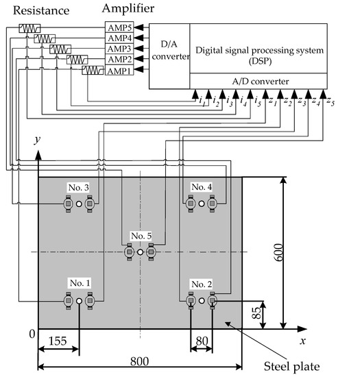
Figure 1.
Electromagnetic levitation control system.
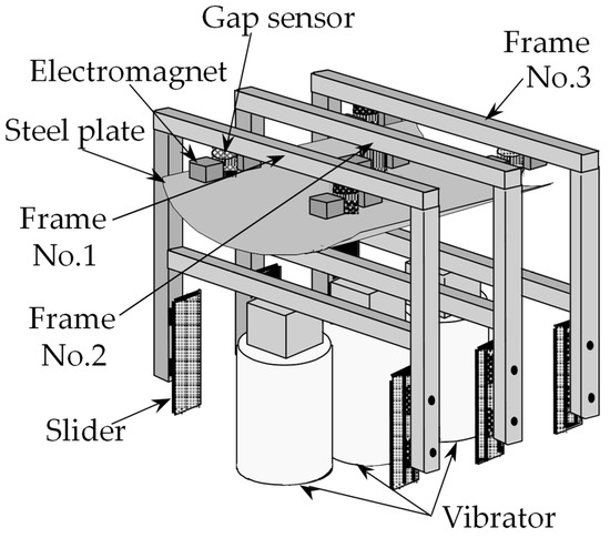
Figure 2.
Schematic illustration of the experimental apparatus.
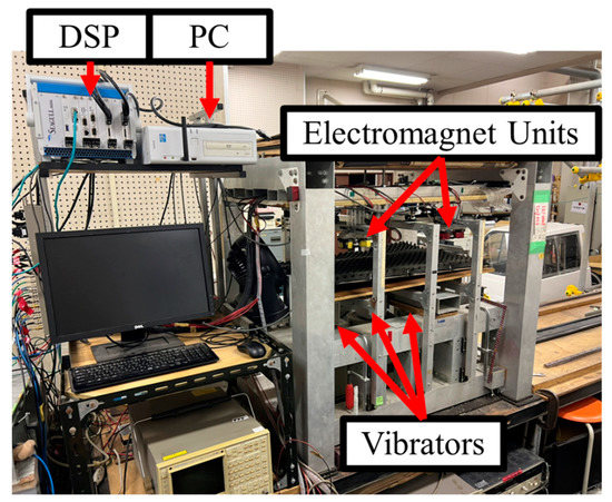
Figure 3.
Photograph of the bending magnetic levitation system (overall view).
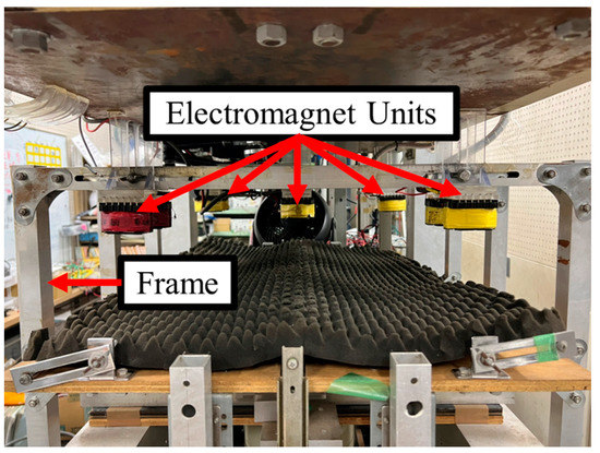
Figure 4.
Photograph of the bending magnetic levitation system (side view).
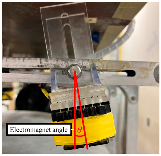
Figure 5.
Photograph of an electromagnet angle.
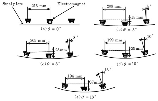
Figure 6.
Relationship between the tilt angle of the electromagnets θ and the shape of a steel plate.
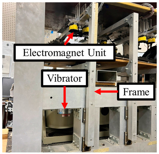
Figure 7.
Photograph of the vibrators and frames.
Modeling of Steel Plate
In this research, the one—degree—of—freedom model with a simple design is applied as a model of a steel plate. In the one-degree-of-freedom model, the displacement, velocity, and electromagnet coil current value detected by each electromagnet unit are feedback controlled only for that electromagnet unit. Therefore, as shown in Figure 8, the steel plate is divided into five virtual masses, and each is modeled as a lumped constant system. The electromagnet coil current value is measured using the resistance part, as shown in Figure 9. In addition, the power is supplied to one electromagnet unit by one amplifier, as shown in Figure 10.
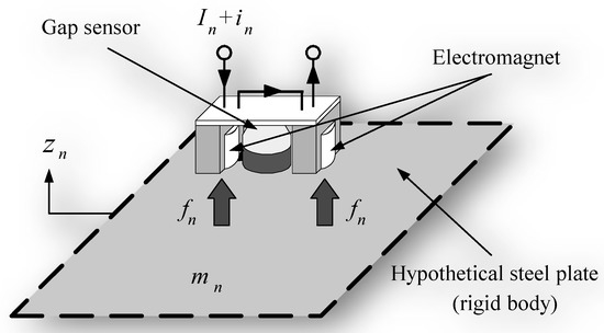
Figure 8.
Theoretical model of levitation control.
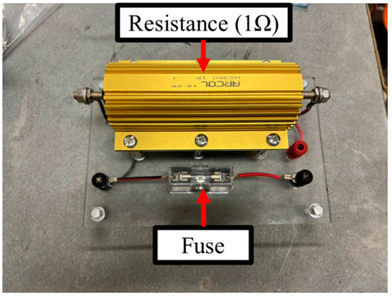
Figure 9.
Photograph of the resistance part.
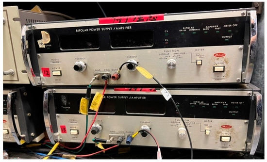
Figure 10.
Photograph of the amplifier.
If the steel plate is levitated by the static attraction force from the electromagnet unit, there is an equilibrium state Z0 that can be maintained at a constant distance. Assuming that the displacement in the vertical direction is zn, the equation of motion is as follows. In all the symbols, the subscript n indicates No. one–five of the electromagnet unit (n = 1~5).
Here, mn is the mass of the steel sheet, and the mass m is divided into five virtual (kg), where fn is the attractive force per electromagnet (N). The equations for the attractive force of the electromagnet and the current flowing through the electromagnet coil obtained by linearization approximation are as follows.
The inductance Ln (H) of the coil per electromagnet in the equilibrium levitation state is expressed as follows.
Here, Fn is the constant attractive force generated from the two electromagnets of each electromagnet unit (N), Z0 is the distance between the surface of the electromagnet unit and the surface of the steel plate in the equilibrium state (m), In is the steady current of the electromagnet coil in the equilibrium state (A), in is the fluctuation value from In (A), Ln is the inductance per electromagnet coil in an equilibrium state (H), Rn is the resistance value of the electromagnet (Ω), vn is the electromagnet coil fluctuation value from the steady voltage (V), kem is the induction that effectively acts on the steel plate per electromagnet (Hm), and Llea is the leakage magnetic flux per electromagnet (H). Using the displacement zn, velocity , and current of the steel plate as state variables, Equations (1) to Equation (4) are rearranged to obtain the following equation of state. Figure 11 shows a block diagram of the control system.
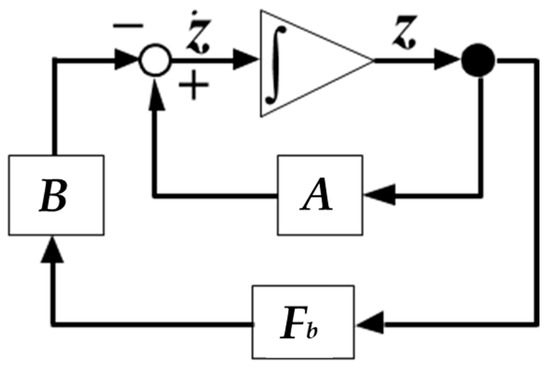
Figure 11.
Block diagram.
The feedback gain was determined by the optimum control theory as previously reported [23]. The feedback gain is shown in Table 1.

Table 1.
Feedback gain.
3. Levitation Experiment under Pulse Disturbances
To identify the frequency band of random noise representing disturbance conditions, experiments were carried out by applying pulse wave vibrations to the frames on which the electromagnets were attached. The resonant frequency of the steel plate was obtained from the spectra measured by the displacement sensors. Figure 12 presents the time series displacement of vibrating frames excited by a pulse disturbance. The resonance frequency of the magnetic levitation steel plate is defined as the frequency at which the displacement spectrum shown in Figure 13 has the maximum value. The maximum amplitude value for the electromagnet is 0.049 mm, and the frequency at which the maximum amplitude is obtained is 6.5 Hz, which is defined as the resonant frequency. Therefore, it was confirmed that the resonant frequencies at θ = 0–13° existed in the band from 0 to 10 Hz.
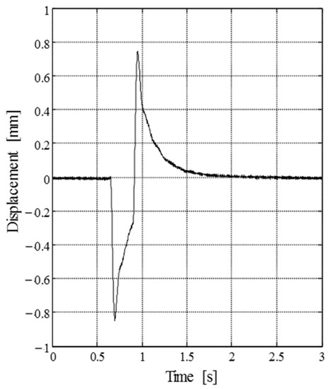
Figure 12.
The time series of frame displacement data for a pulse disturbance.
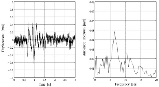
Figure 13.
Bending levitation results when vibrating the frames using pulse disturbances (θ = 8°).
4. Levitation Experiment under Random Disturbances
Since the magnetic field changes with the square of the distance between the electromagnet and the steel plate, the vibration of the steel plate affect the levitation stability. Therefore, it is necessary to evaluate the vibration of the steel plate. In order to evaluate the levitation performance, the displacement standard deviation was calculated from the time series of the displacement measured by the displacement sensor. This indicates the magnitude of vibration in the steel plate. Random disturbances in the frequency range from 0–10 Hz were imposed on all three frames, as shown in Figure 2, and an evaluation of the levitation was performed by comparing the standard deviation of the displacement for each electromagnet angle. Figure 14 presents the time series displacement of vibrating the frames using random disturbances. Figure 15 presents the relationship between the standard deviation of the displacement measured at the No. 1 electromagnet unit shown in Figure 1 and the electromagnet angle in cases with and without disturbances. From Figure 15, compared to the case without disturbances, one can see that the standard deviation of the displacement increased in the presence of disturbances and that the vibration of the steel plate also increased. Additionally, when the electromagnet angle increases, the standard deviation of the displacement of the steel plate decreases, and the vibration is suppressed. One can see that the standard deviation of the displacement is the lowest at the electromagnet angle of θ = 8° and that the vibration is heavily suppressed. However, if the angle of the electromagnet increases to more than θ = 8°, the standard deviation of the displacement increases, and the vibration tends to increase.
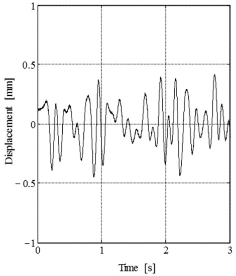
Figure 14.
Time series data of vibrating frame displacement under random disturbances.
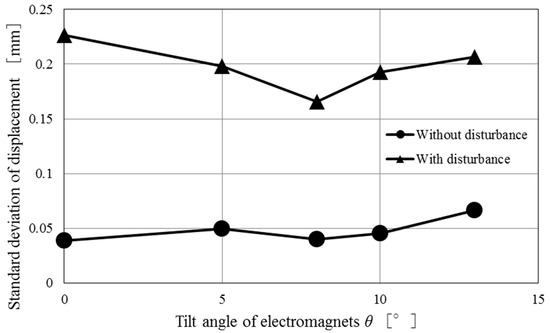
Figure 15.
The relationship between the standard deviation of displacement and the electromagnet angle in cases with and without disturbances.
5. Conclusions
In this study, we conducted experiments on levitation performance when an electromagnet was vibrated in a bending levitation system using the steel plate whose thicknesses were different from the previous study. From the experimental results, it is confirmed that the steel plate can be levitated stably at a tilt angle which is estimated by an analytical method, and the optimal angle is constant even when the disturbance was input or not. Furthermore, we determined that it is possible to achieve stable levitation in the presence of external disturbances when levitating a steel plate at the optimal bending angle. These obtained results can be expected to find optimal levitation parameters using analytical methods even if the size of the steel plate, for example, the width, length, and thickness, changes. In the future, based on the results of this study, we would like to ensure a higher levitation performance in order to apply the bending magnetic levitation system to the steel plate transfer process. In addition, the electromagnet used in this paper has a wire diameter of 0.5 mm and 1005 turns, but the inductance varies depending on the specifications of the electromagnet. Therefore, we plan to investigate the effect on the steel plate vibration when the specifications of the electromagnet are changed.
Author Contributions
Conceptualization, H.K.; methodology, R.M.; software, A.E.; validation, K.I. and T.K.; formal analysis, K.O.; investigation, K.O. and D.U.; resources, H.K.; data curation, Y.U., I.K. and J.K.; writing—original draft preparation, K.O.; writing—review and editing, Y.U.; visualization, Y.U.; supervision, R.M. and H.K.; project administration, T.N.; funding acquisition, T.N. All authors have read and agreed to the published version of the manuscript.
Funding
This research received no external funding.
Data Availability Statement
Not applicable.
Conflicts of Interest
The authors declare no conflict of interest.
References
- Christian, K.; Andreas, K.; Wolfgang, K. Optimal force control of a permanent magnet linear synchronous motor based on a magnetic equivalent circuit model. Control Eng. Pract. 2022, 122, 105076. [Google Scholar]
- Mateo, B.; Dinko, V. Vector control system of a self-excited induction generator including iron losses and magnetic saturation. Control Eng. Pract. 2013, 21, 395–406. [Google Scholar]
- Zhen, S.; Hao, J.; Liu, X.; Wu, Q.; Zhao, H.; Chen, Y.H. A practical robust bounded control for permanent magnet linear motor with inequality constraints. Control Eng. Pract. 2022, 122, 105068. [Google Scholar] [CrossRef]
- Yaojung, S.; Mahendra, B.K.; Chang-Bo, W. New Actuation Control for Hybrid Electromagnetic Valve Train. Appl. Sci. 2022, 12, 10449. [Google Scholar]
- Asano, Y.; Mizuguchi, A.; Amada, M.; Asama, J.; Chiba, A.; Ooshima, M.; Takemoto, M.; Fukao, T.; Ichikawa, O.; Dorrell, D.G. Development of a Four-Axis Actively Controlled Consequent-Pole-Type Bearingless Motor. IEEE Trans. Ind. Appl. 2009, 45, 1378–1386. [Google Scholar] [CrossRef]
- Krzysztof, K. Modification of Electromechanical Coupling in Electromagnetic Harvester. Energies 2022, 15, 4007. [Google Scholar]
- Joanna, B.; Tomasz, T.; Marcin, S.; Zygmunt, K. Modelling and Investigation of Energy Harvesting System Utilizing Magnetically Levitated Permanent Magnet. Sensors 2022, 22, 6384. [Google Scholar]
- Hamidreza, M.; Ali, Z.; Rajesh, R. Magnetic position estimation using optimal sensor placement and nonlinear observer for smart actuators. Control Eng. Pract. 2021, 112, 104817. [Google Scholar]
- Rajiv, T.; Prabhat, K. An innovative virtual trial misalignment approach for identification of unbalance, sensor and active magnetic bearing misalignment along with its stiffness parameters in a magnetically levitated flexible rotor system. Mech. Syst. Sig. Proces. 2022, 167, 1085440. [Google Scholar]
- Murakami, I.; Zhao, Y.; Tashiro, T. Stabilization of a Magnetic Repulsive Levitation Flywheel System Using a High-Efficiency Superconducting Magnetic Bearing. Actuators 2022, 11, 180. [Google Scholar] [CrossRef]
- Georg, S.; Martin, B.; Martin, H.; Josef, Z.; Clenn, G. Control of a magnetic levitation system with communication imperfections: A model-based coupling approach. Control Eng. Pract. 2013, 58, 161–170. [Google Scholar]
- Fengqiu, X.; Kaiyang, Z.; Xianze, X. Development of Magnetically Levitated Rotary Table for Repetitive Trajectory Tracking. Sensors 2022, 22, 4270. [Google Scholar]
- Dahoon, A.; Ji-Won, J.; Hyeeun, Y.; Jaeheon, J. Development of a Novel Dual Servo Magnetic Levitation Stage. Actuators 2022, 11, 147. [Google Scholar]
- Mizuno, T.; Takasaki, M.; Kishita, K.; Hirakawa, K. Vibration isolation system combining zero-power magnetic suspension with springs. Control Eng. Pract. 2007, 15, 187–196. [Google Scholar] [CrossRef]
- Ranhee, Y.; Birhan, A.N.; Wonhee, Y.; Jungyoul, L.; Jinho, L.; Changyoung, L.; Kwansup, L. Capsule Vehicle Dynamics Based on Levitation Coil Design Using Equivalent Model of a Sidewall Electrodynamic Suspension System. Energies 2021, 14, 4979. [Google Scholar]
- Fujita, K.; Sugiura, T. Characterization of LCR Parallel-Type Electromagnetic Shunt Damper for Superconducting Magnetic Levitation. Actuators 2022, 11, 216. [Google Scholar] [CrossRef]
- Laith, S.I.; Ciprian, L.; Hamid, A. Design of Adaptive-RST Controller for Nonlinear Magnetic Levitation System Using Multiple Zone-Model Approach in Real-Time Experimentation. Appl. Syst. Innov. 2022, 5, 93. [Google Scholar]
- Lidia, M.B.; Eva, S.; Antonio, F.C.; José, A.S.; Rafael, M. Generalised Proportional Integral Control for Magnetic Levitation Systems Using a Tangent Linearisation Approach. Mathematics 2021, 9, 1424. [Google Scholar]
- Nihal, D.; Dipankar, D.; Muyeen, S.M. A Reference Model Assisted Adaptive Control Structure for Maglev Transportation System. Electronics 2021, 10, 332. [Google Scholar]
- Rahul, S.G.; Soundarya, S.; Kavitha, P.; Yuvaraja, T.; Ramya, K.; Shabana, U. Enhanced Model Reference Adaptive Control Scheme for Tracking Control of Magnetic Levitation System. Energies 2021, 14, 1455. [Google Scholar]
- Suzuki, O.; Nagashima, D.; Nishimura, K.; Nakagawa, T. Magnetic Levitation Control by Considering the Twisting Mode of a 0.18 mm Thick Steel Plate. IEEE Trans. Magn. 2015, 51, 8600304. [Google Scholar] [CrossRef]
- Cheng, T.L.; Yung, Y.Y.; Sheng, Y.L. On-line realizations of dynamic gap detection and control for levitated industrial steel plate conveyance system. In Proceedings of the 2012 IEEE Industry Applications Society Annual Meeting, Las Vegas, NV, USA, 7–11 October 2012. [Google Scholar] [CrossRef]
- Kato, H.; Marumori, H.; Yonezawa, H.; Narita, T. Vibration Suppression Effect in a Bending-Levitated Flexible Steel Plate by the Electromagnetic Force. J. Vib. Acoust. 2016, 138, VIB-15-1159. [Google Scholar] [CrossRef]
- Marumori, H.; Yonezawa, H.; Narita, T.; Kato, H.; Oshinoya, Y. Consideration on bentmagnetic levitation apparatus for thin steel plate. Trans. JSME 2015, 81, 14-00471. [Google Scholar] [CrossRef]
- Tada, M.; Yonezawa, H.; Marumori, H.; Narita, T.; Kato, H.; Moriyama, H. Vibration suppression effect in a maglev system for flexible steel plate with curvature. Int. J. Appl. Electromagn. Mech. 2019, 59, 993–1001. [Google Scholar] [CrossRef]
Publisher’s Note: MDPI stays neutral with regard to jurisdictional claims in published maps and institutional affiliations. |
© 2022 by the authors. Licensee MDPI, Basel, Switzerland. This article is an open access article distributed under the terms and conditions of the Creative Commons Attribution (CC BY) license (https://creativecommons.org/licenses/by/4.0/).