Abstract
With the development of aerospace technology, hypersonic flight vehicles are evolving towards larger size, lighter weight, and higher performance. Their cross-domain maneuverability and extreme flight environment led to the rigid–flexible coupling effect and became the core bottleneck restricting performance improvement, seriously affecting flight stability and control accuracy. This paper systematically reviews the research status in the field of control for high-speed rigid–flexible coupling aircraft and conducts a review focusing on two core aspects: dynamic modeling and control strategies. In terms of modeling, the modeling framework based on the average shafting, the nondeformed aircraft fixed-coordinate system, and the transient coordinate system is summarized. In addition, the dedicated modeling methods for key issues, such as elastic mode coupling and liquid sloshing in the fuel tank, are also presented. The research progress and challenges of multi-physical field (thermal–structure–control, fluid–structure–control) coupling modeling are analyzed. In terms of control strategies, the development and application of linear control, nonlinear control (robust control, sliding mode variable structure control), and intelligent control (model predictive control, neural network control, prescribed performance control) are elaborated. Meanwhile, it is pointed out that the current research has limitations, such as insufficient characterization of multi-physical field coupling, neglect of the closed-loop coupling characteristics of elastic vibration, and lack of adaptability to special working conditions. Finally, the relevant research directions are prospected according to the priority of “near-term engineering requirements–long-term frontier exploration”, providing Refs. for the breakthrough of the rigid–flexible coupling control technology of the new-generation high-speed aircraft.
1. Introduction
In recent years, with the rapid advancement of aerospace technology, the design and control of hypersonic flight vehicles have garnered significant attention. As strategic aerospace equipment, it is characterized by cross-domain maneuverability (with speeds ranging from subsonic to over Mach 5, and flight altitudes extending from the troposphere to near space) and multi-mission adaptability (integrating reconnaissance and surveillance, rapid strike, aerospace transportation, and other composite functions). Technological breakthroughs in such aircraft not only serve as a concentrated reflection of the advancement of aerospace science and technology but also provide a crucial underpinning for national strategic security and the safeguarding of aerospace rights and interests.
The complexity of space missions and rapid advancement of advanced materials/technologies have driven the hypersonic aircraft toward large-scale, lightweight, and high-performance designs. However, extreme operating environments (e.g., transonic shock oscillations, high-Mach aerodynamic heating, rarefied atmospheric viscous effects) and structural features (large flexible components, lightweight composites) have made rigid–elastic coupling a core bottleneck limiting performance. For example, extensive lightweight structures lead to low-frequency structural modes in high-speed aircraft. Under aerodynamic loads, control commands, and external disturbances, these elastic modes are excited and dynamically exchange energy with rigid-body motions (pitch, roll, yaw), enhancing rigid–elastic coupling effects (Figure 1). Weakly damped modes further degrade closed-loop control system robustness and accuracy, impairing mission execution. Traditional rigid-aircraft analysis methods fail to meet modeling requirements. Thus, an urgent need exists for a rigid–elastic coupling dynamic model accounting for elastic vibrations—critical for addressing these issues and improving overall aircraft performance.
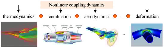
Figure 1.
Nonlinear coupling dynamics in hypersonic flight vehicles.
Physically, rigid–elastic coupling refers to the dynamic interaction between aircraft rigid-body motions (e.g., attitude angle changes, center-of-mass trajectory) and elastic vibrations (e.g., wing bending, tail flutter). In engineering practice, positive feedback between the control loop and elastic modes may trigger divergent chatter, structural damage, or even control system failure, manifesting as follows:
- Hypersonic cruising stage: Aerodynamic heating degrades structural material stiffness, perturbing the body’s dynamic parameters and introducing significant nonlinearity—requiring control parameters to adapt accordingly. Thus, traditional linear control methods may fail; nonlinear compensation or adaptive mechanisms are therefore needed to adjust control parameters online and ensure stability. Elastic vibration-induced angle-of-attack fluctuations reduce the lift–drag ratio, significantly impacting control system stability and accuracy; a more effective robust control strategy is therefore required.
- Large Angle-of-Attack Maneuver Stage: During large angle of attack or rapid maneuvering, the aircraft faces high overload demands—even approaching the critical threshold of its available overload capacity. In this state, energy exchange between the aircraft’s low-frequency rigid-body motion and high-frequency elastic modes (e.g., 1 Hz rigid-body pitch motion exciting the 20 Hz wing bending mode) can amplify lateral flutter amplitude to 200% of the critical value [1]. Additionally, fuel tank oscillation couples with the fuselage’s elastic vibration, degrading guidance accuracy. These factors pose significant challenges to the aircraft’s structural strength and attitude control stability.
- Multi-body separation stage: Shock loads from interstage separation excite vibrations of the flexible adapter, whose excited modal frequency is close to that of the attitude control system. This forms closed-loop coupling with the attitude control system, inducing roll oscillations of the test vehicle and leading to separation failure or structural damage [2].
Rigid–flexible coupling is a typical nonlinear dynamics problem at the intersection of rigid-body dynamics, structural vibration, and fluid mechanics. The core scientific challenge stems from the complex dynamic behaviors induced by multi-scale and strongly coupled nonlinear effects, specifically including the following:
- Modal interaction effect: The nonlinear energy exchange between the rigid-body mode and the elastic mode, as well as between different-order elastic modes, breaks the assumption of modal independence, leading to the mismatch of the control law and triggering the “modal capture” phenomenon, which significantly reduces the robustness margin.
- Frequency overlap effect: The frequencies of elastic modes (10–50 Hz) are likely to overlap with the attitude control bandwidth (5–20 Hz), forming a positive-feedback resonance that causes the vibration amplitude to increase exponentially and destroys the closed-loop stability.
- Amplitude-dependent effect: When the amplitude of elastic vibration exceeds the critical value, the material and geometric nonlinearities cause changes in the structural stiffness, leading to the mismatch of control parameters and forming a vicious cycle of “increased stiffness–gain mismatch–intensified vibration”.
Therefore, revealing the physical mechanism of rigid–elastic coupling, establishing accurate dynamic models, and developing effective control strategies have become “bottleneck” technologies that urgently need to be addressed in the design of wide-envelope aircraft.
In the existing relevant reviews in this field, there are limitations in research perspectives. Some focus on the classification of control strategies but do not delve into the closed-loop coupling effect. Some emphasize the passive suppression of servo-aeroelastic but lack the collaborative design of sensing and control. Some regard structural flexibility and fuel sloshing as independent problems, and some do not analyze intelligent control in combination with the special requirements of the rigid–flexible coupling scenario. In contrast, the novelty of this review is reflected in the following aspects: firstly, it forms a comprehensive chain analysis of “perception–decision–execution” from a closed-loop coupling perspective; secondly, it incorporates the decentralized sub-problems into a unified modeling and control framework; and thirdly, it strengthens the cross-domain fusion analysis of transformative technologies and proposes a future paradigm of “active collaboration–cross-domain fusion–intelligent autonomy”.
This review aims to sort out the research results at home and abroad in recent years. Focusing on the key technologies and existing problems of rigid–flexible coupling control, it explores the technological trends and application prospects, providing Refs. for relevant research.
2. Research on Rigid–Elastic Coupling Modeling of Aircraft
2.1. Definition of Coordinate System of Rigid–Elastic Coupling
For conventional aircraft, elastic vibration and rigid-body motion are typically analyzed independently. Specifically, elastic vibration is generally described relative to the stationary undeformed configuration, while rigid-body motion is characterized by the origin and axis orientation of a Ref. frame moving with the vehicle—these two use distinct Ref. frames. The Ref. frame adopted for modeling must be capable of describing both elastic vibration and rigid-body motion: its origin and axis orientation describe the rigid-body motion, and elastic vibration is represented by the motion of aircraft microelements relative to this Ref. frame.
Waszak derived a flight dynamics model for elastic aircraft using the Lagrangian equation under the mean axis system assumption [3]. In the Waszak model, the translation and rotation equations are consistent with traditional rigid-body dynamics models, with coupling between elastic and rigid-body degrees of freedom only manifested in aerodynamic loads (no direct coupling terms exist). The model also assumes that elastic deformations are sufficiently small to not affect the inertia tensor, further simplifying the dynamic formulation. Scholars have predominantly adopted the Waszak model for dynamic modeling of elastic hypersonic vehicles.
For the X-30 hypersonic vehicle, Chavez and Schmidt first estimated an aircraft’s first-order elastic mode via the finite element method and then calculated surface forces using Newtonian impact theory. They obtained fluid parameters for each engine component using one-dimensional compressive flow theory and the momentum theorem to establish a thrust model, ultimately developing a dynamic model incorporating aerodynamic/propulsive/elastic structural coupling effects based on the Waszak model [4]. Building on this, Schmidt further refined the model by incorporating the influences of rotating components, wind, and Earth’s rotation [5].
For the X-43A aircraft configuration, Doman et al. calculated steady aerodynamic forces using oblique shock wave and Prandtl–Meyer expansion wave theory, computed the fuselage’s elastic modes via cantilever beam theory, and established a propulsion system model using one-dimensional compressible flow theory. They ultimately derived an elastic hypersonic vehicle dynamic model based on the Waszak framework [6].
Qu Xin, Ren Zhang, and colleagues took the AFRL/RBCA hypersonic vehicle as the research object, establishing a longitudinal model for hypersonic aircraft considering propulsion and elastic characteristics using the Waszak model [7]. Zhu Qiangjun and Tang Shuo approximated the slender hypersonic vehicle fuselage as a freely supported beam, modeling the rear fuselage/external nozzle via the virtual shock-expansion wave method, influence coefficient method, and piston theory to develop a more accurate dynamic model for elastic air-breathing hypersonic vehicles [8].
Zhang Xibin, Zong Qun, et al. established the elastic model using the assumed mode method, the aerodynamic model via shock-expansion wave theory and piston theory, and the thrust model using one-dimensional compressible flow theory. After model simplification through fitting, they proposed a control-oriented elastic hypersonic aircraft model based on the Waszak model [9,10].
Meirovitch and Nelson initially conducted dynamic modeling for spacecraft with elastic attachments using an undeformed vehicle’s rigidly connected coordinate system [11]. Subsequently, Meirovitch extended this method to elastic aircraft dynamic modeling [12]. Later, he performed finite element analysis on different aircraft components using the component mode synthesis method to derive the elastic aircraft dynamic equation [13].
Building on these two coordinate systems, Guo et al. proposed a new framework called the transient coordinate system [14]. Like the undeformed vehicle’s rigidly connected coordinate system, its axes remain fixed; however, its origin always coincides with the aircraft’s center of mass (consistent with the mean axis system). Thus, this coordinate system integrates the advantages of both the rigidly connected coordinate system and the mean axis system: it accurately describes the influence of elastic deformation on the center of mass position while overcoming the “quasi-velocity” issue inherent in the undeformed vehicle’s rigidly connected coordinate system, enabling more precise characterization of the interactions between aerodynamics, structural dynamics, and flight dynamics. Based on this, Guo Dong et al. derived the elastic aircraft dynamic equation [14], which comprehensively describes both rigid-body motion and elastic vibration. However, this approach increases the equation’s complexity and the computational cost of its solution, making it difficult to directly apply to overall aircraft design and guidance-control system development.
Currently, the mean axis system and the rigidly connected coordinate system of the undeformed aircraft—widely adopted for elastic aircraft modeling—have difficulty accurately characterizing elastic vibration and rigid-body motion, whereas the transient coordinate system offers advantages in this aspect. Therefore, selecting an appropriate coordinate system and developing a dynamic model capable of comprehensively capturing the characteristics of elastic hypersonic vehicles constitutes one of the fundamental and key issues for research in this field.
Each of the three coordinate systems has its own applicable scenarios and limitations. The average axis system is the first choice in engineering due to the simplicity of the model. It is suitable for cruising conditions with relatively small elastic deformation and weak coupling effects. However, it ignores the direct coupling between elastic degrees of freedom and rigid-body degrees of freedom, and the error can reach 10–15% in strongly coupled scenarios, such as high-angle-of-attack maneuvers [6]. The undeformed aircraft-fixed coordinate system can more accurately describe the influence of elastic deformation on motion. However, the “quasi-velocity” problem leads to a decrease in accuracy during transient response analysis, and it is only suitable for steady-state flight modeling [13]. The transient coordinate system combines the advantages of the above two, with a more comprehensive description of coupling. However, the computational complexity is 3–5 times higher than the previous two. Currently, it is only used for high-precision simulations, and it needs to be simplified through model reduction techniques (such as the balanced truncation method) before it can be applied to engineering design [14]. The selection of the model needs to be comprehensively determined based on flight conditions, accuracy requirements, and computing resources. The average axis system is preferred during the cruising phase. The transient coordinate system (after reduction processing) can be selected for high-maneuver or significant structural deformation scenarios. The undeformed aircraft-fixed coordinate system can be considered for steady-state analysis.
Table 1 compares the three coordinate systems from different dimensions, providing direct Refs. for the design of control strategies and engineering selection.

Table 1.
Comparison of different coordinate systems.
2.2. Elastic Mode and Sensor Layout
In the existing literature, scholars generally employ the multi-body dynamics approach combined with elastic mechanics theory to develop mathematical models of rigid–elastic coupling systems [15]. A typical method involves separately modeling the rigid and elastic components of the aircraft, before achieving their coupling via coordinate transformation and state feedback [16]. While this approach can effectively characterize the aircraft’s dynamic behavior under various operating conditions, its separate modeling paradigm tends to overlook the coupling effects between rigid and elastic components. For instance, considering the influence of elastic vibration, the elastic vibration process can be expressed in the equation form of vibration mode and generalized coordinates:
where and represent the i-th generalized coordinates of the first-order vibration of the pitch and yaw channels, respectively. , , , and denote the corresponding generalized force and generalized mass. , , , and represent the corresponding vibration frequency and damping ratio, respectively.
Some researchers have attempted to introduce nonlinear dynamics theory to explore complex oscillation phenomena in rigid–elastic coupling systems. The results indicate that the rigid–elastic coupling effect exerts a significant influence on system stability: when the aircraft operates in extreme flight environments, elastic modes can induce high-frequency oscillations, which, in turn, lead to control system failure. Additionally, the coupling effect significantly alters the aircraft’s aerodynamic characteristics, causing it to exhibit distinct states in high-altitude, high-speed environments compared to low-speed flight.
Sensor layout optimization involves identifying vibration feature-sensitive positions on the aircraft surface, arranging sensors, and collecting local displacement and pressure data during elastic vibration in real time. For elastic aircraft, sensor measurement signals contain both rigid-body motion information and elastic vibration components [17]. The elastic vibration components are converted into rudder deflection commands via the control system, which, in turn, affects structural elastic vibration—thereby significantly impacting flight attitude stability and even potentially damaging the aircraft structure.
Domestic and international scholars have carried out relevant research on this problem. Ge Dongming and Huang Xianlin analyzed the dynamic characteristics of elastic hypersonic aircraft, concluding that control–structure coupling renders the system highly sensitive to sensor placement; unreasonable sensor arrangement may induce system instability [18]. Li Xiru et al. investigated the structure–control coupling effect, proposing that elastic deformation impacts should be considered in control system design and advocating the use of a hybrid method to mitigate elastic vibration influences [19]. Zong et al. studied the aero-servoelasticity of hypersonic glide vehicles, finding that disturbance-induced generalized forces can excite elastic vibrations, which further affect the aircraft’s aerodynamic forces and moments [20]. Qian et al. analyzed the aero-servoelastic stability of the entire system from a frequency-domain perspective, providing a foundation and Ref. for control system design [21]. Wei et al. examined the rigid-body–elasticity–control coupling problem of elastic hypersonic aircraft in both time and frequency domains, noting that the low natural frequency of hypersonic aircraft structures—close to the control system’s frequency band—renders traditional structural notches ineffective in suppressing elastic noise [22].
An optimization algorithm based on the Geometric Dilution of Precision (GDOP) for the precise positioning of supersonic projectile impact points was proposed in Ref. [23]. Through the accurate calculation of parameters (e.g., the projectile impact accuracy area), the optimal sensor layout within a specific range can be determined by this method. Similar approaches have also been extended to other fields. A multi-objective optimization design model that comprehensively considers aerodynamics, structure, and radar performance was established in Ref. [24] to satisfy the mission requirements of a joined-wing UAV, yielding favorable optimization results. Additionally, classical frequency-domain analysis was adopted in Ref. [25] to investigate the sensor layout in the servoelastic mode of large-aspect-ratio aircraft.
In summary, there is a significant coupling effect between the excitation of elastic modes and the liquid sloshing in the fuel tank: elastic vibration will be transmitted to the liquid through the tank wall, causing the sloshing amplitude to increase, and the inertial force generated by fuel sloshing will react on the missile structure, further intensifying the elastic vibration, forming a closed-loop coupling of “elastic vibration–liquid sloshing”. This coupling effect is particularly prominent during high-angle-of-attack maneuvers and fuel consumption processes. Therefore, elastic mode modeling, sensor layout, and fuel sloshing modeling need to be analyzed as a whole to comprehensively characterize the dynamic characteristics of the rigid–elastic coupling system.
2.3. Fuel Tank Liquid Shaking Model
To meet complex multi-mission requirements, spacecraft are required to carry increased volumes of liquid propellant. Specifically, liquid propellant mass accounts for 50–90% of the total spacecraft mass, depending on the spacecraft type. Consequently, the issue of liquid fuel sloshing in spacecraft tanks has increasingly emerged as a key research focus.
Liquid fuel sloshing in tanks alters the spacecraft’s natural frequency and dynamic characteristics. This not only impairs attitude stability and navigation accuracy but also induces fatigue damage of the tank structure [26], significantly affecting the overall spacecraft dynamics [27]. For instance, fuel sloshing can trigger longitudinal coupled vibration (i.e., POGO vibration), which induces resonance between propellant lines and engine thrust fluctuations. Notably, U.S. ballistic rockets, including Redstone, Jupiter, and Hercules, as well as the Soviet Cosmos series, have all suffered orbital deviations or even crashes due to intense propellant sloshing in boosters [28]. Therefore, establishing an elastic model that accurately incorporates fuel sloshing is of great significance for ensuring spacecraft operational safety.
Research on propellant sloshing primarily encompasses two aspects: modeling and control strategies. To accurately characterize the dynamic behavior of liquid sloshing, researchers have developed various mathematical models. Among these, the rigid-body pendulum composite model is a widely used approach, enabling effective characterization of multiple motion modes, such as the overall rigid-body motion of liquid relative to the tank and lateral sloshing of the free liquid surface [29]. Additionally, the variable-parameter rigid-body pendulum composite model further accounts for changes in tank fill level, making it suitable for investigating the large-scale motion coupling dynamics of nonlinear sloshing liquid-filled spacecraft during fuel depletion.
Another widely adopted modeling method is the nonlinear Zener model, which can describe the vertical vibration characteristics of viscoelastic vibration isolation systems. Stability conditions of the system can be derived using the multi-scale method and Routh–Hurwitz criterion [30].
From the control perspective, the attitude control system can be optimized by integrating coupling dynamics simulation and active control techniques. On the one hand, coupling simulations of multi-body dynamics (MBD) and computational fluid dynamics (CFD) are employed to accurately analyze the interaction between liquid sloshing and spacecraft motion, laying a foundation for control strategy design. On the other hand, improving the attitude control algorithm enables real-time compensation for disturbances induced by liquid sloshing, ensuring spacecraft attitude stability during large-angle attitude maneuvers.
In summary, the actual sensor layout and fuel sloshing deeply interfere with the dynamic characteristics and control stability of the system from the aspect of measurement feedback and internal excitation, respectively. On the one hand, if the sensor is arranged at the part where the elastic deformation of the missile is significant, its measurement signals (such as attitude angle and angular velocity) will inevitably mix the elastic vibration modes, resulting in the control system generating wrong control surface commands based on the “distortion” information, which will instead stimulate the vibration of the missile structure, forming an unstable coupling closed loop of “rigid-body elasticity control”. On the other hand, the sloshing of fuel in the tank will produce time-varying hydrodynamic forces and moments, which not only directly change the rigid-body dynamic parameters, such as the centroid position and moment of inertia of the missile, but also cause strong “sloshing structure” dynamic coupling if its specific sloshing frequency is close to the low-order elastic modal frequency of the missile, which will significantly aggravate the structural load and attitude oscillation. Therefore, improper sensor arrangement will amplify the interference of the elastic mode on control, while imprecise fuel sloshing modeling cannot accurately characterize this important internal excitation source. The combined effect of these factors may cause the coupling instability risk between rigid-body motion, elastic vibration, and liquid sloshing in theory to be excited and amplified in the live ammunition system, seriously affecting the attitude stability and control accuracy of the aircraft.
2.4. Research on Multi-Physical Field Coupling Modeling
The essence of the rigid–flexible coupling system is the interaction of multiple physical fields (structural field, fluid field, control field, and thermal field). Among them, thermal–structural–control coupling and fluid–structural–control coupling are the key factors affecting the performance of high-speed aircraft. In recent years, certain progress has been made in relevant research, but there are still many challenges:
- Thermal–structural–control coupling modeling: During hypersonic flight, aerodynamic heating can cause the structural temperature to reach over 1200 °C, leading to material stiffness degradation, the generation of thermal stress, and a shift in elastic modes (the first-order modal frequency decreases by 5–10% [22]), which, in turn, affects the adaptability of control law parameters. The existing modeling methods mainly include the following: ➀ finite element–control coupling simulation, which calculates the structural temperature distribution through the heat conduction equation and then substitutes the temperature-dependent stiffness matrix into the dynamic model [31]; ➁ the simplified thermoelastic model, which equates the thermal effect to parameter perturbation and uses the linear parameter-varying (LPV) model to describe the thermal–structural coupling characteristics [32]; and ➂ data-driven modeling, which uses deep learning (e.g., CNN-LSTM network) to fit the nonlinear mapping relationship of thermal–structural–control and predict the control response under thermal environment. The current challenges include the large difference in the time scales of heat conduction and structural dynamics (heat conduction is in seconds, while structural vibration is in milliseconds), resulting in low efficiency of coupling simulation. It is difficult to accurately characterize the uncertainty of material parameters under extreme temperatures.
- Fluid–structural–control coupling modeling: Flow field characteristics such as transonic shock wave oscillation and rarefied atmosphere viscous effect form a strong coupling with structural elastic vibration and control loops. The existing methods include the following: ➀ aero-servoelastic (ASE) modeling, which uses piston theory and the dipole lattice method to calculate the unsteady aerodynamic force and forms a coupling model in combination with the structural dynamic equation [20]; ➁ co-simulation of computational fluid dynamics (CFD) and multi-body dynamics (MBD), which accurately capture the dynamic interaction between the flow field and the structure [33]; and ➂ reduced-order modeling technology (e.g., Proper Orthogonal Decomposition, POD), which performs reduced-order processing on CFD data to reduce the computational complexity of the coupling model [4]. There are still limitations in engineering applications: the computational cost of CFD-MBD co-simulation is extremely high, making it difficult to be used for real-time control; the accuracy of the reduced-order model depends on the sampling conditions, and its generalization ability is insufficient.
3. Research Status of Rigid–Elastic Coupling Control Strategy
Compared with traditional aircraft, hypersonic aircraft exhibit high flight speed, high flight altitude, a wide flight envelope, fast time-varying characteristics, significant nonlinearity, strong coupling effects, uncertainties, and numerous control constraints. These features pose significant challenges to control system design, making their control methods a persistent research hotspot.
3.1. Linear Control Method
Control methods for hypersonic aircraft are categorized into linear and nonlinear approaches. Initially, research on hypersonic aircraft control adopted traditional linear control strategies: the nonlinear model was linearized at the equilibrium point using small-disturbance linearization theory, followed by control system design based on linear control theory.
Linear control methods for hypersonic aircraft control are developed based on feedback-linearized dynamic models. For instance, controllers were designed from the perspective of linear feedback in Refs. [34,35,36,37]. In Ref. [38], after model feedback linearization was implemented, an adaptive full-order terminal chattering-free sliding mode control law was developed, which ensures the system converges to the desired value within finite time while eliminating chattering. A control method based on a disturbance observer was proposed in Ref. [39], which mitigates the effects of disturbances. An adaptive fixed-time control method was presented in Ref. [40], which accelerates system convergence and addresses the issue of actuator saturation. A composite control paradigm was adopted in Ref. [41], where a compensator was designed to suppress the impact of uncertainties and ensure the stability and robustness of the closed-loop control system. A finite-time time-varying sliding mode controller design approach was proposed in Ref. [42]. In Refs. [43,44], the state correlation coefficient method was employed to linearize the nonlinear model, and predictive controllers as well as optimal composite controllers were developed to enhance the robustness of the control system.
Linear control methods rely on the linearization of nonlinear systems. However, in practical applications, the strong nonlinearity of hypersonic aircraft and uncertainties in mathematical models limit the effectiveness of linear control methods—this has motivated the development of advanced control strategies.
3.2. Nonlinear Control Method
Linear control methods fail to meet the control performance requirements of hypersonic vehicles, prompting research efforts to gradually shift toward nonlinear control approaches. Nonlinear control methods are directly designed based on nonlinear models, enabling effective handling of nonlinearity, uncertainties, and other key challenges. The primary nonlinear control strategies for hypersonic vehicles include robust control and sliding mode variable structure control.
Common robust control approaches include H∞ control and backstepping control. Robust control methods primarily target systems with uncertainties and are relatively mature control algorithms. They are particularly significant for hypersonic vehicles—nonlinear systems that are challenging to model and exhibit inherent uncertainties.
Traditional robust control (e.g., H∞ control [45]) handles structural/non-structural uncertainties but has inherent conservatism. Performance-guaranteed control mitigates this by enabling gradual stabilization, disturbance suppression, and minimized controller gain under secondary performance indices.
Since the 1990s, linear matrix inequalities (LMIs) [46] have been widely applied in multiple fields. Ref. [47] proposed a nonlinear compensation-based robust tracking controller for hypersonic vehicles, achieving high-accuracy tracking and strong robustness against uncertainties/disturbances. Ref. [48] applied feedback linearization to the longitudinal model’s inputs/outputs and developed a robust compensation-based nonlinear control method.
Ref. [32] proposed an LPV-based robust gain-scheduling control method for hypersonic vehicles’ nonlinear models, simplifying controller design and suppressing parameter variations. Ref. [31] approximated the nonlinear model via linear models over a wide flight envelope, designing an LPV controller with a digital switching algorithm for speed tracking. Ref. [49] developed a signal compensation-based robust control method, decomposing the vehicle model into a nominal model and equivalent disturbances.
Ref. [50] proposed an fault-tolerant quantized control for flexible air-breathing hypersonic vehicles, effectively suppressing system uncertainties. Ref. [51] developed an H∞-based robust flight controller for the longitudinal model to mitigate uncertainties and nonlinear effects.
Tan et al. [52] designed an adaptive robust controller via backstepping and a second-order filter, ensuring stable tracking under parameter perturbations. Ref. [53] proposed a robust backstepping method integrated with a disturbance observer and Kalman filter to address measurement noise/uncertainties, yielding favorable tracking performance. Ref. [54] designed a robust anti-windup and fault-tolerant controller for longitudinal cruise phase tracking under multiple disturbances. Ref. [55] developed a fixed-time stability-based robust compensator to offset system uncertainties.
In hypersonic vehicle research, robust control is integrated with other methods. Ref. [56] applied genetic and stochastic robust control algorithms to strongly nonlinear models, accounting for uncertain parameter variations.
Robust control suppresses perturbations and compensates for unmodeled dynamics but relies on worst-case scenario design, increasing system complexity. Compensation mechanisms also add tuning parameters, enhancing parametric uncertainty.
Variable structure control (VSC), or sliding mode control (SMC) [57], is a discontinuous nonlinear control method. Its structure adapts to system states to guide the system along predefined trajectories, featuring flexible sliding mode design and insensitivity to parameters/disturbances for exceptional robustness.
Since the 1950s, SMC has evolved into an independent research field, widely applied in nonlinear/complex systems and hypersonic vehicle control. Gao Weibing [58] designed VSC schemes for aerospace and flexible space vehicles. Ref. [59] developed a terminal sliding mode, adaptive law, and fixed-time disturbance observer to ensure hypersonic vehicle attitude tracking stability and robustness.
Ref. [60] proposed a model-free intelligent PID control strategy based on an adaptive neural network global fractional-order fast terminal sliding mode, shortening convergence time, eliminating singularities, and enhancing robustness. Ref. [61] presented a predefined-time fractional-order time-varying SMC controller to improve anti-disturbance performance. Ref. [62] designed an active adaptive continuous non-singular terminal SMC algorithm for higher control accuracy and response speed. Ref. [63] constructed an adaptive terminal SMC via a high-order linearized model and integrated it with a radial basis function neural network, enabling fast tracking under parameter perturbations and actuator failures.
Ref. [64] proposed a parameter-adaptive non-singular terminal SMC method for flexibly coupled air-breathing hypersonic vehicles’ longitudinal control, using adaptive approximation law gain to address uncertainties and enhance robustness. Ref. [65] proposed a non-singular fast terminal SMC fault-tolerant control method considering preset performance for attitude tracking under disturbances and actuator failures; simulations verified its excellent fault tolerance.
A key challenge in sliding mode control (SMC) is chattering, which is induced by discontinuous control resulting from switching motion on both sides of the sliding surface. Although this issue can be mitigated through switching function replacement, sliding surface optimization (e.g., the super-twisting algorithm), adaptive gain mechanisms, and observer-based compensation, there remains a need to further integrate novel online control strategies or dynamic compensation mechanisms tailored to the high-speed and large-angle maneuvering characteristics of hypersonic vehicles. This will enable the design of more effective SMC strategies to enhance the controller’s disturbance rejection and chattering suppression capabilities.
3.3. Intelligent Control Method
In recent years, with the advancement of artificial intelligence algorithms and adaptive theory, numerous novel or integrated intelligent control strategies have been proposed (Figure 2), such as model predictive control (MPC), adaptive control, neural network control, prescribed performance control, etc.
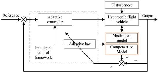
Figure 2.
The structure of a general intelligent control system.
Model predictive control is a control approach that predicts future outputs via the dynamic model of the controlled plant and obtains optimal solutions through rolling optimization. It exhibits superior control performance for the uncertainties and fast time-varying characteristics of nonlinear systems. However, the inclusion of the rolling optimization component imposes a significant computational burden, which restricts the controller’s response speed to a certain extent.
Ref. [66] proposed a constrained NMPC strategy integrating approximate linearization and predictive control, validated via simulations. Ref. [67] presented a robust predictive control approach for precise hypersonic vehicle state regulation and parameter perturbation resistance.
Ref. [68] applied MPC to hypersonic vehicle longitudinal models, satisfying constraints and achieving favorable performance. Ref. [69] proposed a GPC-adaptive hybrid control strategy with excellent results for air-breathing hypersonic vehicles. Ref. [70] developed a hierarchical predictive control strategy with strong applicability under concurrent disturbances.
To reduce predictive controller computation load, Ref. [71] proposed a continuous predictive sliding mode controller combining SMC anti-disturbance and predictive optimization. Ref. [72] presented a fuzzy observer-based predictive sliding mode strategy for altitude tracking, yielding a high-precision, robust system.
Neural network control, with strong online approximation capability, is widely used in HSV control. Lu Bo et al. [73] designed a neural network dynamic inverse controller to compensate for HSV model uncertainties. Cheng et al. [74] proposed an adaptive RBF neural network dynamic surface controller. Waseem et al. [75] used neural networks to approximate unknown nonlinear terms. Bu et al. [76] applied RBF neural networks to approximate elastic coupling terms and derived the optimal weight adaptive adjustment law.
However, neural network parameter tuning limits practical applications. For RBF neural networks, optimal weights, centers, and influence ranges are hard to obtain; adaptive laws are used for weights, while centers and ranges are empirically determined, reducing approximation accuracy.
Thus, reasonable tuning of key parameters (e.g., weights, centers) is critical for engineering applications, and system stability analysis remains an urgent research issue.
Modern nonlinear control research focuses on steady-state performance, neglecting transient indicators (e.g., regulation time, overshoot). For complex systems, transient performance considerations are essential to improve control accuracy and real-time responsiveness [77].
Prescribed performance control (PPC) [78] defines a bounded region for tracking errors, ensuring transient metrics meet requirements and balancing steady-state and transient performance.
Bechlioulis et al. [79] extended PPC to MIMO systems. Kostarigka et al. [80] developed an output feedback controller for non-affine nonlinear systems. Bechlioulis et al. [81] studied PPC for strict-feedback nonlinear systems. Shou et al. [82] designed an aerodynamic/ reaction-jet compound control of hypersonic reentry vehicle using sliding mode control and neural learning. Sui et al. [83] proposed a PPC-adaptive-output feedback controller for nonlinear stochastic systems.
The HSV control system is a relatively complex system with stringent requirements for control accuracy and real-time responsiveness. Notably, prescribed performance control (PPC) can precisely meet these strict control performance demands, thereby holding significant engineering application potential in HSV control system design. However, PPC has been predominantly applied to robotic arm control system design, while its application in flight control system development remains limited.
In recent years, learning-based control methods have gradually overcome the limitations of “black-box optimization.” By integrating physical mechanisms and stability constraints, these methods have emerged as a cutting-edge approach in rigid–flexible coupling control. The core advancements are concentrated in two categories: data-driven adaptive control and reinforcement learning (RL) control with stability guarantees.
Data-driven adaptive stable control: Chen et al. proposed an adaptive robust control method based on kernel ridge regression (KRR) [84]. They used KRR to fit the unknown nonlinear terms of the rigid–flexible coupling system online and proved the uniform ultimate boundedness (UUB) of the closed-loop system by constructing a Lyapunov function. In a longitudinal control simulation of a flexible aircraft, the attitude tracking error was controlled within ±0.3°, and the stability proof was more rigorous compared to traditional RBF neural network control. Liu et al. proposed a data-driven model Ref. adaptive control (MRAC) [85]. By training the initial adaptive law parameters with an offline dataset and only requiring a small amount of real-time data for online correction, this method solved the problem of slow parameter convergence in traditional ACMR. In a scenario with sudden changes in elastic modes, the parameter convergence time was reduced by 60%, and the exponential stability of the tracking error was ensured.
Reinforcement learning control with stability constraints: Yang et al. proposed a deep reinforcement learning control strategy based on a barrier Lyapunov function (BLF) [86]. They transformed constraints such as attitude angles and elastic vibration amplitudes into BLF inequalities and incorporated them into the reward function design of the Deep Q-Network (DQN). In a high-maneuver scenario of a hypersonic aircraft, this strategy not only increased the elastic vibration suppression efficiency to 85% but also avoided instability caused by control input saturation, providing a clear stability boundary for the application of RL control in rigid–flexible coupling systems for the first time. Wang et al. proposed a hybrid strategy combining Proximal Policy Optimization (PPO) and sliding mode control [87]. Leveraging the robustness of sliding mode control to ensure the basic stability of the system and optimizing the control parameters through PPO, this strategy improved the system robustness by 25% compared to pure RL control in the presence of aerodynamic parameter perturbations (±20%).
The core breakthrough of these methods lies in solving the engineering pain point of “difficult to guarantee stability” in traditional learning control. However, there are still some deficiencies. Data-driven methods require a high degree of dataset coverage, and the lack of data under extreme operating conditions can easily lead to a degradation of control performance. The training process of RL control relies on a high-precision simulation environment, and the “domain shift” problem between the simulation and the real flight environment has not been fully resolved. Moreover, most studies still focus on single-channel control (such as longitudinal attitude control) and lack verification in multi-channel coupling scenarios.
3.4. Rigid–Elastic Coupling Control Method
Rigid–elastic coupling control of aircraft is a typical interdisciplinary research topic, involving flight mechanics, structural dynamics, control theory, and materials science. Traditional vibration suppression approaches do not rely on external energy input or real-time feedback mechanisms (Figure 3); instead, they enhance rigid–elastic coupling stability by optimizing the aircraft’s structural design and material properties, thereby modifying the inherent physical characteristics of the aircraft itself.
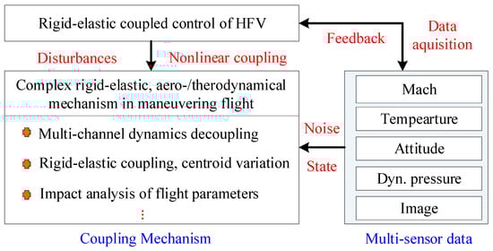
Figure 3.
Composite disturbance and complex dynamic coupling mechanism of hypersonic aircraft.
Specifically, during the aircraft structural design phase, methods such as topology optimization and size optimization are employed to adjust the structural stiffness and mass distributions. This increases the frequency of key elastic modes, separating them from the control system’s bandwidth and the dominant rigid-body motion frequencies to fundamentally mitigate coupling intensity. Alternatively, composites with high specific stiffness and high damping characteristics—such as carbon fiber-reinforced polymer (CFRP) composites—can improve the structure’s natural frequency and damping ratio while achieving weight reduction.
Building on this foundation, modern control strategies incorporate sensing, decision-making, and actuation components (e.g., sensors, controllers, and actuators) to construct closed-loop control systems, actively counteracting the adverse effects of rigid–elastic coupling. Thus, this review focuses solely on summarizing relevant research from two perspectives: the optimal configuration of measurement devices and the active/passive control of elastic vibrations.
Most existing hypersonic vehicle control methods are still based on rigid-body models, where elastic vibrations are treated as disturbances or model uncertainties. The robustness of the control strategy is then leveraged to mitigate the impacts of elastic vibrations. However, this approach assumes that rigid-body attitude information can be directly measured while overlooking the coupling and superimposition effects of elastic deformation and vibration on rigid-body attitude measurements.
In reality, a complete rigid–elastic coupling control system typically consists of three components: perception (measurement), decision-making (control law), and actuation (execution). Specifically, elastic vibration signals enter the control loop via sensors to form a closed loop, which directly impacts control performance—thus, they cannot be simply treated as disturbances.
3.4.1. Optimal Configuration of Measuring Devices
Accurate and reliable sensing of rigid-body motion and elastic vibrations serves as a prerequisite for effective control. The optimal configuration of measurement devices aims to place sensors in the most economical and effective manner, acquiring information that optimally reflects the system’s critical states. Accordingly, relevant studies have been conducted from the perspective of sensor placement optimization to mitigate the impact of vibrations and other interfering signals on the control system. Existing measurement devices can be roughly categorized into several types:
- Inertial Measurement Unit (IMU): Typically installed near the vehicle’s center of mass (CoM), it is used to measure the angular rate and linear acceleration of rigid-body motion. However, the IMU output is a superimposed signal of rigid-body motion and elastic vibrations, which introduces measurement noise. Moreover, direct utilization of this output may excite elastic modes.
- Rate Gyroscopes (RGs) and Accelerometers: These can be installed in a distributed arrangement at key locations (e.g., wings and tail surfaces) to directly measure the vibrational angular rates and accelerations of local structures. They serve as the primary data sources for constructing elastic modal observers.
- Global Positioning System (GPS) and Vision Sensors: These provide rigid-body position and attitude information to support state estimation.
- New Sensors (e.g., Fiber Bragg Gratings, FBGs): They possess the advantages of being lightweight, anti-electromagnetic interference (EMI) capable, and easy for distributed deployment, making them highly suitable for strain and vibration measurement of hypersonic vehicle structures.
The core objective of optimal configuration is to minimize the number of sensors or maximize modal identifiability while satisfying observability and robustness requirements. Relevant research primarily falls into three categories:
- Methods Based on Modal Observability: This method calculates the observability Gram matrix or eigenvector orthogonality between each sensor position and the target elastic modes through analysis of the system’s state-space model. Optimization algorithms (e.g., genetic algorithm (GA) and particle swarm optimization (PSO)) are employed to determine the sensor distribution scheme that maximizes the observability index of the target modes.
- Energy/Contribution-Based Approaches: These approaches analyze the output energy of sensors at different positions or their contribution to controller performance under specific modes, prioritizing positions sensitive to the response of key elastic modes.
- Robust Configuration Methods: Considering model uncertainties (e.g., aerodynamic parameter variations, structural damage), robustness indices are incorporated into the optimization process to ensure the sensor system maintains favorable sensing performance even under parameter perturbations.
For instance, an optimal process model was developed by Yuan Jianping [88] using modern control techniques, with the optimal placement of inertial measurement units (IMUs) investigated. The correctness of the model was validated using two performance indices: minimum vibration energy and minimum output noise. Generalized vibration energy was adopted as the performance index for the parameterized optimal process by Xu Zhi [89], and a calculation method for IMU placement based on the maximum principle was established—exhibiting significant engineering application potential.
Output feedback control and IMU placement for air-breathing hypersonic vehicles were investigated by Jankovsky [90], with two output feedback control approaches proposed. First, flexible-body system state reconstruction was applied to state feedback control. Second, a robust design approach that does not rely on observers was adopted to ensure stability within a given flight envelope. A model of rate gyroscopes (RGs) and accelerometers was established with elastic effects considered, and an IMU placement strategy was developed for hypersonic vehicle models to enhance observability or retain certain system structures conducive to robust control design. The effectiveness of the IMU placement strategy and the performance of the output feedback control methods were verified by simulation results.
However, IMU configuration optimization methods demand high-precision structural modeling and analysis of the vehicle. A key current challenge lies in addressing the high-dimensional optimization problems induced by large-scale flexible structures. Additionally, achieving collaborative optimization of sensor configuration and control law design remains a major challenge for elastic vibration suppression.
3.4.2. Active and Passive Control Strategies
Based on the configuration of measurement devices and corresponding measurement data, numerous control strategies have been proposed to address the rigid-body–elastic–control coupling issue, aiming to suppress or eliminate elastic vibrations.
Conventionally, designing a structural notch filter based on the elastic vibration mode characteristics of the aircraft is a common approach to ensure system amplitude stability and achieve vibration suppression. Its core objective is to filter out the elastic resonant frequency components of the aircraft so that the signal detected by the inertial measurement unit (IMU) is frequency-wise close to the rigid-body mode. This avoids introducing high-frequency oscillations into the control system. The resonant frequency of the notch filter must be carefully tuned to align as closely as possible with the resonant frequency of the bending mode [91], thereby preventing the introduction of undesirable dynamics.
In engineering practice, the elastic mode frequencies of the aircraft are obtained via conventional testing methods, and notch filters are primarily designed for the first-order elastic vibration mode. However, when the structural vibration frequency is low and its bandwidth overlaps with that of the control system, the notch filter’s suppression effect on elastic noise will be diminished or even ineffective [92]. Since in-flight changes in the aircraft’s mass and material properties induce dynamic variations in vibration modes, adaptive notch filters [93] and adaptive control methods [94] have been extensively adopted in recent years [95].
In recent years, the advancement of modern control theory has facilitated the introduction of methods such as disturbance observers (DOBs) [96], sliding mode control (SMC) [97], extended state observer (ESO)-based control [98], and adaptive control into controller design, aiming to address the elastic vibration suppression problem of hypersonic vehicles. These approaches treat elastic vibrations as rigid-body model uncertainties, enhancing control performance by improving controller robustness and adopting disturbance suppression or compensation mechanisms. Notably, they do not require additional actuators or control surfaces, nor do they alter the aircraft’s original aerodynamic layout—making them more straightforward to implement compared to active control approaches.
However, these methods necessitate consideration of the aircraft’s rigid–flexible coupling model, which increases modeling complexity and renders control law design more intricate. For hypersonic vehicles subject to external disturbances, Ren [99] characterized the influence of elastic modes on the altitude subsystem as a system disturbance, establishing an equivalent model and designing a compensation method based on a disturbance observer. The simulation results demonstrated that the system achieves favorable tracking performance. Nevertheless, this method is only applicable to high-altitude control systems, featuring a low control bandwidth and weak coupling with elastic modes.
Therefore, several integrated control strategies combined with notch filters have been proposed. Specifically, digital or analog filters are incorporated into the control law to significantly attenuate the gain at specific elastic mode frequencies, thereby preventing mode excitation.
An attitude control scheme for statically unstable hypersonic vehicles considering low-frequency aerodynamic servoelastic effects was proposed by Piao et al. [100]. Linear active disturbance rejection control (LADRC) is employed by this scheme to address strong uncertainties and coupling effects. In response to low-frequency aerodynamic servo elasticity, phase-gain hybrid stabilization technology is embedded within the LADRC framework to suppress structural modes. Subsequently, two adaptive aerodynamic servoelastic mode stabilization methods were further proposed by Piao et al. [101] to tackle the coupling among aerodynamics, low-frequency structural modes, and flight control systems of statically unstable air-breathing hypersonic vehicles. Phase stability conditions under the LADRC framework are derived by the first method to achieve self-stabilization of elastic modes. An adaptive notch filter based on a lattice structure and a fast recursive square root algorithm is introduced by the second method. It was demonstrated by simulation results that both methods can achieve adaptive vibration suppression and extend the control bandwidth under elastic mode frequency variations. However, the primary focus of these methods is on stabilizing aerodynamic servoelastic modes, and issues such as attitude angle steady-state errors are still encountered.
An active, robust control scheme-based subsystem controller was designed by Pu [102] to enhance the attitude control performance of elastic vehicles, with the scheme rooted in nonlinear dynamic inversion. It is assumed that elastic states are not fed back, and elastic modes are treated as disturbances to rigid-body dynamics. Various uncertainties are estimated by an extended state observer (ESO), and a compensation law is constructed accordingly. Notch filters are integrated into subsystem controllers corresponding to specific modes to prevent high-frequency signals generated by estimation results from exciting flexible modes. It was indicated by simulations that the proposed method can suppress both uncertainties and flexible modes to a certain degree.
Additionally, active control technology for elastic vibrations has been gradually developed and applied. This technology involves installing additional actuators on a vehicle to form a negative feedback system that actively cancels or suppresses rigid–elastic coupling vibrations. To date, it has been implemented on several experimental vehicles.
For instance, a robust control law-based controller for the Mini_MUTT full-aircraft model was developed by Theis et al. [103] using the ailerons of the airframe model as control inputs. Measurements of center-of-mass acceleration, pitch rate, and wingtip acceleration were incorporated into the controller, with favorable vibration suppression performance achieved. Active control research was conducted by Gao Qian [104] using additional control surfaces, with additional aerodynamic forces and control forces incorporated into the vehicle model. Controllers were designed separately for the rigid-body subsystem and the vibration subsystem, resulting in a combined vibration-damping controller. It was demonstrated by simulation results that under this combined controller, not only is attitude control precision ensured by the vehicle but vibrations are also effectively suppressed.
However, active control technology still requires further testing and research on large-scale vehicles or unmanned aerial vehicles (UAVs), featuring a long research and development (R&D) cycle, high experimental risks, and substantial investment.
In summary, the existing control strategies can be divided into two categories:
- Disturbance suppression method: Regarding elastic vibration as a disturbance, its influence is eliminated through robust control, disturbance observers, etc. This method is suitable for scenarios where the elastic mode frequency is far from the control bandwidth and the vibration amplitude is small (such as the cruise phase). However, it has a large steady-state error (up to 5–8%) in scenarios with large maneuvers and strong coupling.
- Explicit elastic state feedback control: The elastic vibration state is directly measured by sensors, and a dedicated controller is designed to actively suppress the vibration. This method is suitable for scenarios where the elastic mode is close to the control bandwidth and the vibration amplitude is large (such as large-angle-of-attack maneuvers). However, it requires additional sensors to be installed, which increases the system complexity. In engineering, dynamic switching is required according to flight conditions: the disturbance suppression method is used in the cruise phase to simplify the system, and the explicit feedback control is switched to in the large-maneuver phase to ensure accuracy.
Modern rigid–elastic coupling control has transformed from “single passive optimization” or “single active suppression” to “active–passive collaborative control”. The core is to achieve dual optimization of vibration suppression and attitude control through the in-depth linkage of structural design (passive) and control law optimization (active). The existing collaborative strategies mainly include the following:
- Collaborative design of structure and control: In the topological optimization stage, with the constraint of “minimizing control energy consumption”, the structural stiffness distribution is adjusted to keep the key elastic mode frequencies away from the control bandwidth. After the application in a certain type of hypersonic glide vehicle, the active control energy consumption is reduced by 35% [99].
- Integrated application of smart materials: Piezoelectric ceramics, shape memory alloys, etc., are used as structural components (passive load-bearing) and actuators (active suppression). The piezoelectric active damping structure applied by NASA on the X-57 verification aircraft has achieved millisecond-level suppression of wing bending vibration [98].
- Collaborative control of passive damping and active compensation: Medium- and low-frequency vibrations are attenuated by high-damping composite materials (passive), and then the high-frequency residual vibrations are compensated for by an adaptive notch filter (active) to solve the problem of insufficient high-frequency vibration suppression by single passive control [96].
3.4.3. Comparison of Different Control Methods
To clarify the adaptability of different control methods in the rigid–flexible coupling scenario, Table 2 presents a systematic comparison of mainstream control methods based on various key indicators, providing a Ref. for engineering applications and subsequent research.
Table 2.
Comprehensive comparison table of control methods.
Table 3 compares the adaptation degrees of different control methods in the rigid–flexible coupling problem and their applicable mechanisms.
Table 3.
Comparison table of coupling problems of different control methods.
3.4.4. Digital Twin-Oriented Rigid–Flexible Coupling Control
The rise of digital twin technology has provided a new paradigm of “physical entity–virtual mirror–real-time interaction” for rigid–flexible coupling control. In recent years, research focuses have been concentrated in three directions: real-time mapping, virtual closed-loop control, and full-life cycle optimization.
- Real-time mapping based on multi-source data fusion: In 2023, Zhang et al. proposed a rigid–flexible coupling dynamic modeling method based on a digital twin [105]. Through the multi-source data fusion of distributed FBG sensors, IMUs, and GPS, a high-precision digital twin of the aircraft was constructed to achieve millisecond-level synchronous mapping of elastic vibration, structural thermal deformation, and rigid-body attitude. In the simulation of a certain type of flexible missile, the dynamic response error between the twin and the physical entity was less than 3%, providing accurate state feedback for control decisions.
- Virtual closed-loop control and pre-decision: In 2022, Li et al. designed a digital twin-driven feedforward–feedback composite control architecture [106]. By using the twin to simulate the rigid–flexible coupling responses under different control strategies, the excitation trend of elastic vibration was predicted in advance, and the optimal feedforward control instructions were generated to cooperate with the online feedback control. During the hypersonic cruise phase, the amplitude of elastic vibration was reduced by 40% compared with the traditional feedback control, and the lag of the control loop was reduced.
- Full-life-cycle health management and control optimization: In 2024, Chen et al. proposed a control strategy combining a digital twin and federated learning [107]. The twin accumulates the flight data of multiple aircraft, and federated learning is used to train a general control model. At the same time, for the individual characteristics of a single aircraft, such as structural aging and elastic mode drift, the control parameters are fine-tuned online to achieve the optimization mode of “general model + personalized correction”, thus extending the effective life cycle of the control system.
Current research related to digital twin technology is still in the simulation verification stage. The data transmission delay in the real flight environment (for example, the data transmission delay of FBG sensors can reach 10 ms) will affect the real-time performance of a twin. The modeling accuracy of a twin with multi-physical field coupling depends on the calibration of a large amount of experimental data, resulting in high engineering costs. Moreover, a standardized interaction protocol between a twin and a physical entity has not been formed, which limits its deployment on actual aircraft.
3.4.5. Parameter Sensitivity Analysis
The control performance of the rigid–flexible coupling system is highly correlated with the core parameters (elastic frequency, structural damping, stiffness change induced by thermal effect, and fuel mass). The dynamic fluctuations in these parameters will directly affect the adaptability of the control bandwidth, the system stability margin, and the attitude/vibration control accuracy. The following is a concise analysis of the influence mechanism of the key parameter changes based on the existing research data and engineering practice:
- Influence of Elastic Frequency Change: The elastic modal frequency is the core parameter determining the adaptability of the control strategy. Its fluctuation mainly affects the control performance through the “frequency matching degree”.
- Influence of Structural Damping Change: Structural damping directly determines the attenuation rate of elastic vibration. Its insufficiency is the key factor leading to the difficulty in vibration suppression.
- Influence of Stiffness Change Induced by Thermal Effect: Aerodynamic heating during the hypersonic cruise phase (the wall temperature can reach 500–1000 °C) will cause significant degradation of the structural stiffness, indirectly affecting the control performance.
- Influence of Fuel Mass Change: The fuel mass accounts for a high proportion (50–90%) and is dynamically consumed. Its change affects the control performance in two ways through “centroid migration + modal coupling”.
3.5. Consider the Control Method of Fuel Shaking
Regarding fuel tank sloshing control, three primary approaches dominate: model predictive control (MPC), viscoelastic damping, and active control.
MPC, an advanced method, is pivotal for aircraft tank sloshing control. Elastic tube model-based predictive control adaptively adjusts the “tube” shape per the rolling optimization horizon’s endogenous characteristics and load prediction accuracy, balancing robustness and optimization economy [108]. Self-triggered MPC (STMPC) is also widely applied—for example, an elastic STMPC strategy with critical data protection saves system resources and enhances accuracy by safeguarding key control samples [109].
Viscoelastic damping and active control are also critical. The Active Magnetic Elastic Ring Dry Friction Damper (AMERDFD) suppresses dual-rotor vibration by adjusting the damper’s positive pressure via electromagnetic actuators [110]. In soft robotics, magnetorheological elastomer variable stiffness provides new insights for sloshing control [111].
Haghparast addressed parameter identification and output feedback attitude stabilization for liquid-propellant satellites with fuel sloshing, describing sloshing via a two-degree-of-freedom pendulum. The diaphragm’s flexibility and fuel viscosity in passive strategies were modeled with a torsional spring–damper system. An adaptive backstepping control is developed for air-breathing hypersonic vehicle with actuator dynamics [112].
Boundary feedback control is a typical active control method that suppresses fuel sloshing by adjusting parameters at the tank wall [113,114]. In recent years, Lyapunov function-based approaches have been widely applied to such problems, achieving favorable control performance [115,116].
Notably, diverse technical paths for fuel sloshing control have been explored in relevant studies. A fuel use strategy optimization approach was proposed by Alessia et al. [33] to maximize the damping benefits from wing tank sloshing, thereby reducing aircraft design loads. The smoothed particle hydrodynamics (SPH) method and distributed parameter method were adopted by Kai et al. to model and analyze liquid-filled flexible spacecraft, with a focus on their complex coupling characteristics [117]. An efficient coupling dynamic model for liquid-filled space robots was established by Lu Yu et al. via an alternating iterative algorithm, aimed at minimizing the deviation of liquid fuel from its initial position [118].
Besides the aforementioned methods, other advanced control strategies have also been applied to fuel sloshing control. Fuzzy sliding mode control integrates the fast response of traditional sliding mode control with the flexibility of fuzzy logic, achieving stable control under uncertain conditions [119,120]. Adaptive control methods are also widely used due to their strong robustness [121]. Composite control, an organic integration of multiple strategies, aims to leverage respective advantages for superior performance [116]; for example, combining input shaping technology with fuzzy control can effectively suppress resonance induced by fuel sloshing.
4. Summary and Outlook
4.1. Research Summary
As the core bottleneck restricting the performance improvement of hypersonic flight vehicles, the modeling accuracy and control robustness of the rigid–elastic coupling effect directly determine the cross-domain maneuverability and mission reliability of an aircraft. At present, research at home and abroad has made phased progress in two core directions: rigid–elastic coupling dynamics modeling and control strategy.
In the modeling field, a classical framework has been established based on the mean axis system and the undeformed aircraft’s body-fixed coordinate system. The Waszak model has emerged as the mainstream tool for elastic hypersonic vehicle modeling, while transient coordinate systems offer a novel approach to describing rigid-body motion and elastic vibrations. To address key issues, including elastic mode coupling, fuel tank sloshing, and variable-structure configuration switching, a modeling approach integrating multibody dynamics and elastic mechanics theory has been developed. Specialized sub-models (e.g., rigid-body–pendulum composite model, nonlinear Zener model) and variable-structure modeling techniques (e.g., Kane’s method, Newton–Euler equations) have been proposed, providing support for characterizing dynamic behaviors under complex operating conditions.
In terms of control strategies, a multi-level technical system covering linear control, nonlinear control, intelligent control, and rigid–elastic coupling control has been established. Linear control laid the foundation for early studies; robust control and sliding mode variable structure control in nonlinear control significantly enhanced the system’s anti-interference capability; and model predictive control, neural network control, and prescribed performance control in intelligent control offered new approaches to addressing uncertainty and transient performance optimization. Targeting rigid–elastic coupling characteristics, specialized technologies (e.g., linear active disturbance rejection control, adaptive notch filters, sensor layout optimization, structural notch filtering) have been developed, initially achieving the synergy between elastic vibration suppression and attitude control.
However, the existing research still has significant limitations. First, it fails to fully characterize multiphysics coupling effects (structural field, flow field, control field, thermal field) at the modeling level, with the trade-off between model complexity and engineering feasibility under transient coordinate systems remaining prominent. Second, at the control level, elastic vibration is mostly treated as a disturbance, ignoring its closed-loop coupling characteristics with the control loop, leading to inadequate steady-state error suppression and insufficient active vibration attenuation capabilities. Third, the characterization of coupling mechanisms and the adaptability of control strategies under special operating conditions (e.g., variable structure, fuel sloshing) need improvement, and issues such as state constraints and actuator saturation have not been fully resolved. Fourth, the depth of cross-domain technology integration is insufficient. Most of the existing research is confined to technological iterations within a single discipline and fails to effectively integrate transformative achievements in fields such as artificial intelligence, smart materials, and high-precision sensing. As a result, research remains at the stage of incremental optimization of the existing control framework, lacking breakthrough innovation and performance leaps. Fifth, there is a lack of experiments and flight-level verification. The existing research mainly focuses on numerical simulations. Most ground experiments are conducted in scaled-down and low-speed scenarios, and flight-level verification is almost non-existent. Moreover, there are no unified verification standards. Consequently, it is difficult to evaluate the engineering practicability of control methods, which restricts the transformation of technology from theory to engineering.
4.2. Research Outlook
Research on rigid–flexible coupling control in the future needs to break through the limitations of traditional “disturbance suppression” and transform towards “active collaborative control”. Innovation should be carried out focusing on the following directions:
4.2.1. Short-Term Engineering Needs
Future research should focus on the most urgent technical bottlenecks in current engineering applications. With the goal of improving the performance of existing systems and reducing engineering risks, it should carry out practical technological improvements:
- Collaborative optimization of sensor layout and control law: To address the high-dimensional optimization problem of large-scale flexible structures, future research should integrate distributed fiber Bragg grating (FBG) sensing technology with multi-objective optimization algorithms (such as the improved particle swarm algorithm); establish a sensor layout model that combines “modal observability–robustness–economy” and realizes the collaborative design of sensor configuration and control law; and solve the problem of system instability caused by the closed-loop coupling of elastic vibration signals.
- Improvement in adaptive notch and active vibration control: Aiming at the problem of the failure of traditional notch filters in low-mode frequency scenarios, future research should combine the disturbance estimation ability of the extended state observer (ESO) with the precise approximation ability of the attention mechanism neural network; develop a composite strategy of notch-active control with adaptive parameter tuning, which can dynamically match the changes in elastic modes without manual intervention; and improve the accuracy and robustness of vibration suppression.
- Collaborative control of fuel sloshing–rigid–flexible coupling: Based on the rigid pendulum composite model and the coupled simulation of multi-body dynamics (MBD) and computational fluid dynamics (CFD), future research should establish an integrated dynamic model of fuel sloshing and rigid–flexible coupling; design a composite control strategy of fuzzy sliding mode-boundary feedback to solve engineering pain points, such as POGO vibration and reduced guidance accuracy caused by liquid sloshing; and meet the large-attitude maneuver requirements of hypersonic vehicles.
- Multi-mode switching control: Current research mainly focuses on a specific flight phase of high-speed vehicles. However, in practical application scenarios, hypersonic vehicles usually operate in a large-envelope maneuvering flight mode. Their complex flight tasks often require designing corresponding controllers for different flight phases. Reasonably switching between controllers can not only adapt to the dynamic needs of multiple phases but also significantly improve the overall dynamic performance of the system. It is worth noting that there are significant differences in rudder effectiveness characteristics under different flight conditions, which further increases the complexity of controller design.
Therefore, when designing the controller, the time-varying nature of state variables and dynamic constraints must be fully considered. By introducing these constraint mechanisms, the problems of state variable constraints and actuator saturation can be effectively addressed, thereby significantly improving the dynamic stability of the system during configuration switching. This design idea not only enhances the adaptability of the controller to complex flight environments but also provides important support for optimizing the overall performance of hypersonic vehicles.
4.2.2. Long-Term Research Directions
To meet the performance leap requirements of a new generation of high-speed vehicles, scholars should rely on cross-domain technology integration to carry out disruptive innovation research:
- Integrated collaborative technology of metamaterials–intelligent control: Future research should break through the limitations of the separate design of traditional structures and control; utilize the programmable mechanical properties of metamaterials (dynamic stiffness adjustment, negative damping effect) to realize the real-time reconstruction of structural mechanical properties at key parts of the vehicle; combine the deep reinforcement learning (DRL) algorithm to train an intelligent decision-making model that can autonomously sense the flight state; and dynamically optimize the matching strategy of metamaterial parameters and controller parameters to achieve the integrated collaboration of “structural adaptability–control self-optimization” and fundamentally improve the system stability under large-envelope maneuvers.
- Autonomous evolutionary control driven by digital twins: Future research should build a trinity architecture of “physical entity–digital twin–cloud brain”. Based on the distributed FBG sensing network, it should collect multi-source heterogeneous data throughout the life cycle. Through edge computing, it should realize real-time data pre-processing and millisecond-level mapping of the digital twin. In addition, future research should use the cloud brain to integrate deep reinforcement learning and federated learning, complete billions of iterations of working condition training in a virtual environment, realize the autonomous iterative update of control strategies and experience sharing among multiple vehicles, and endow the vehicle with “autonomous learning and evolution ability” to cope with complex and unknown working conditions.
- High-precision control with strong cross-scale coupling: For the cross-scale strong coupling problem of “unsteady aerodynamics–structural modes–centroid migration” during the deformation of near-space vehicles, future research should integrate distributed high-precision sensing and the Transformer model to capture the long-time-series-dependent features of multi-physical field coupling and build a dynamic prediction model. It should propose an adaptive model predictive control method with a closed-loop of “sensing–prediction–control” to predict the excitation trend of elastic vibration in advance. Through the collaboration of feed-forward control and feedback correction, future research should achieve nanometer-level attitude control accuracy to meet the strict requirements of future high-precision strikes, space transportation, and other tasks.
- Innovative cross-disciplinary integration: Future research should break the barriers between disciplines, such as machinery, aviation, materials, and computers, and carry out integrated collaborative design of “aerodynamics–metamaterial structure–intelligent control–high-precision sensing”. It should incorporate the requirements of rigid–flexible coupling suppression into the conceptual design stage; focus on complex problems, such as the coupling of multiple physical fields of heat–elasticity–control–fluid; and develop AI-driven, efficient modeling methods. Finally, it should promote the cross-integration of aeroelastic mechanics and material gene engineering and design metamaterials with specific rigid–flexible coupling suppression functions to open up disruptive technological paths for multi-physical field coupling problems.
- Multi-field coupling and error quantification in reduced-order modeling: Future research should develop a multi-field coupling reduced-order framework based on “physical mechanism + data-driven”; integrate the advantages of methods such as POD and Transformer to solve the problem of data scarcity under extreme working conditions; establish an error quantification theory for reduced-order models; clarify the mapping relationship between error boundaries and control performance; and provide reliability guarantees for engineering applications.
- Construction of flight-level verification platform: Future research should rely on the existing hypersonic vehicle test platform; install measurement equipment such as distributed FBG sensors and high-precision IMUs; carry out special flight tests on rigid–flexible coupling control; and establish a three-level verification system of “simulation–ground experiment–flight verification” to ensure the engineering reliability of control methods.
In summary, breakthroughs in short-term engineering needs can quickly improve the control accuracy and reliability of existing high-speed vehicles, while exploration in long-term research directions lays a core foundation for the development of a new generation of high-performance vehicles. The evolution of rigid–flexible coupling control technology should adhere to the principle of “parallel development of engineering implementation and frontier exploration”. Through cross-domain technology integration and continuous theoretical innovation, we can promote the development of this field towards “precision, intelligence, and autonomy” to provide core technical support for safeguarding national aerospace security and strategic interests.
Author Contributions
Conceptualization, R.L. and B.X.; methodology, R.L. and B.X.; validation, R.L. and B.X.; formal analysis, R.L. and W.Y.; investigation, R.L. and W.Y.; resources, B.X. and W.Y.; data curation, R.L.; writing—original draft preparation, R.L.; writing—review and editing, R.L. and B.X.; visualization, R.L. and W.Y.; supervision and project administration, B.X.; funding acquisition, B.X. and W.Y. All authors have read and agreed to the published version of the manuscript.
Funding
This work was partially supported by the National Natural Science Foundation of China (52506117 and 12302382) and Innovation Research Foundation of College of Aerospace Science and Engineering at National University of Defense Technology (KY0505072520).
Data Availability Statement
No new data were created or analyzed in this study. Data sharing is not applicable to this article.
Conflicts of Interest
The authors declare no conflicts of interest.
Abbreviations
The following abbreviations are used in this manuscript:
| AIM | Approximate Inertial Manifold |
| CFD | Computational Fluid Dynamics |
| ESO | Extended State Observer |
| FBG | Fiber Bragg Grating |
| FEM | Finite Element Method |
| HSV | Hypersonic Vehicle |
| IMU | Inertial Measurement Unit |
| LPV | Linear Parameter Varying |
| MBD | Multi-body Dynamics |
| POD | Proper Orthogonal Decomposition |
| RBCA | Robust Control and Adaptive |
| RG | Rate Gyro |
| SMC | Sliding Mode Control |
| STMPC | Self-triggered Model Predictive Control |
| T-S | Takagi–Sugeno |
| VSC | Variable Structure Control |
References
- Chen, H.B.; Zhang, L.T. Experimental Study on Vibration Characteristics of Rigid-Elastic Coupling System. Trans. Chin. Soc. Aeronaut. Astronaut. 2021, 34, 567–576. [Google Scholar]
- Smith, J.; Johnson, C. Kinetics of Multibody Separation, 1st ed.; National Defense Industry Press: Beijing, China, 2019; pp. 234–258. [Google Scholar]
- Martin, R.W.; David, K.S. Flight Dynamics of Aeroelastic Vehicles. J. Aircr. 1988, 25, 563–571. [Google Scholar] [CrossRef]
- Chavez, F.R.; Schmidt, D.K. Analytical Aeropropulsive Aeroelastic Hypersonic Vehicle Model with Dynamic Analysis. J. Guid. Control Dyn. 1994, 17, 1308–1319. [Google Scholar] [CrossRef]
- Bilimoria, K.D.; Schmidt, D.K. Integrated Development of the Equations of Motion for Elastic Hypersonic Flight Vehicles. J. Guid. Control Dyn. 1995, 18, 73–81. [Google Scholar] [CrossRef]
- Bolender, M.A.; Doman, D.B. Nonlinear Longitudinal Dynamical Model of an Air-Breathing Hypersonic Vehicle. J. Spacecr. Rocket. 2007, 44, 374–386. [Google Scholar] [CrossRef]
- Liu, Y.; Chen, B.; Li, Y.; Shen, H. Overview of control-centric integrated design for hypersonic vehicles. Astrodynamics 2018, 2, 307–324. [Google Scholar] [CrossRef]
- Zhu, Q.J.; Tang, S.; Tan, Y.M. Modeling and Analysis of Rear Body/External Nozzle of Hypersonic Elastic Vehicle. Flight Mech. 2012, 30, 48–52. [Google Scholar]
- Zhang, X.B.; Zong, Q.; Zeng, F.L. Modeling and Analysis of Oriented Control of Hypersonic Aircraft Considering Aerodynamic-Propulsion-Elastic Coupling. J. Astronaut. 2014, 35, 528–536. [Google Scholar]
- Zhang, X.B.; Zong, Q. Modeling and Analysis of Control-Oriented Elastomer Hypersonic Vehicle. Control Decis. 2014, 29, 1205–1210. [Google Scholar]
- Meirovitch, L.; Nelson, H.D. On the High-Spin Motion of a Satellite Containing Elastic Parts. J. Spacecr. Rocket. 1996, 3, 1597–1602. [Google Scholar] [CrossRef]
- Meirovitch, L. Hybrid State Equation of Motion for Flexible Bodies in Terms of Quasi-Coordinates. J. Guid. Control Dyn. 1991, 14, 1008–1013. [Google Scholar] [CrossRef]
- Meirovitch, L.; Tuzcu, I. Unified Theory for the Dynamics and Control of Maneuvering Flexible Aircraft. AIAA J. 2004, 42, 714–727. [Google Scholar] [CrossRef]
- Guo, D.; Xu, M.; Chen, S.L. Research on Flight Dynamics Modeling of Elastic Aircraft. J. Aerodyn. 2013, 31, 413–436. [Google Scholar]
- Ding, H.X.; Xu, B.W.; Yang, W.Q.; Zhou, Y.F.; Wu, X.Y. A robust control method for the trajectory tracking of hypersonic unmanned flight vehicles based on model predictive control. Drones 2025, 9, 223. [Google Scholar] [CrossRef]
- Xu, B.W.; Yang, W.Q.; Zhou, Y.F.; Zhao, W.; Wu, X.Y.; Zhang, Z.D.; Liu, Y. A data-driven online estimation method for aerodynamic parameter of high-speed aircraft considering strong nonlinearity and noise. ISA Trans. 2025, 163, 86–97. [Google Scholar] [CrossRef] [PubMed]
- Chen, E.K.; Jing, W.X.; Gao, C.S.; Zhang, Z. An Adaptive Control Approach for a Flexible Hypersonic Glide Vehicle. In Proceedings of the 9th International Conference on Mechanical and Aerospace Engineering, Budapest, Hungary, 10–13 July 2018. [Google Scholar]
- Ge, D.M.; Huang, X.L. Analysis of Dynamic Characteristics of Control-Oriented Hypersonic Aircraft. Aerosp. Control 2010, 28, 3–9. [Google Scholar]
- Li, X.R.; He, J.W.; Hei, L.J. Comprehensive Study on Structure/Control Coupling of Hypersonic Aircraft. Flight Mech. 2013, 31, 57–60. [Google Scholar]
- Zong, Q.; You, M.; Zeng, F.L.; Dou, L. Aeroservoelastic Modeling and Analysis of a Six-DOF Hypersonic Flight Vehicle. Proc. Inst. Mech. Eng. Part G J. Aerosp. Eng. 2016, 230, 1240–1251. [Google Scholar] [CrossRef]
- Qian, W.; Bai, Y.G.; Chen, X.Y.; Lu, T. Aero-Servo-Elastic Analysis of a Hypersonic Aircraft. J. Low Freq. Noise Vib. Act. Control 2018, 37, 534–553. [Google Scholar] [CrossRef]
- Wei, Y.Y.; Hao, M.R.; Duan, G.R.; Patnaik, S. Control Law Design for Elastic Aircraft Based on Intelligent Variable Structure. J. Intell. Fuzzy Syst. 2018, 35, 485–499. [Google Scholar] [CrossRef]
- Xu, H.; Xie, Y.L.; Gao, Q.S.; Chen, X.L. Sensor Layout Optimization Method Based on Projectile Positioning Accuracy Analysis. Piezoelectr. Acousto-Opt. 2024, 46, 264–272. [Google Scholar]
- He, C.; Ma, D.L.; Jia, Y.H. Multi-Objective Optimization Design of Wing Layout Sensor Aircraft. J. Aeronaut. 2021, 42, 237–252. [Google Scholar]
- Yang, W.Q.; Yang, H. Sensor Layout in Servo-Elastic Mode of Large Sine Ratio Aircraft. J. Natl. Univ. Def. Technol. 2018, 40, 1–6. [Google Scholar]
- Cheng, X.D. Modeling Method of Spacecraft Liquid Shaking. J. Anqing Norm. Univ. Nat. Sci. Ed. 1995, 1, 35–37. [Google Scholar]
- Li, Q.; Wang, T.S.; Ma, X.R. Research and Application of Liquid Shaking and Liquid-Solid Coupling Dynamics of Liquid-Filled Spacecraft. Prog. Mech. 2012, 42, 472–481. [Google Scholar]
- Abramson, H.N. The Dynamic Behavior of Liquids in Moving Containers, with Applications to Space Vehicle Technology; National Aeronautics and Space Administration: Washington, DC, USA, 1966; pp. 1–100. [Google Scholar]
- Liu, F.; Yue, B.Z.; Ma, B.L.; Shen, Y.F. Modeling and Analysis of Equivalent Dynamics of Liquid-Filled Spacecraft under Fuel Consumption. Acta Mech. 2020, 52, 1454–1464. [Google Scholar]
- Wang, D.H.; Sun, B.; Liu, C.X.; Zhou, Z.Y.; Liu, Y. Research on Vertical Vibration Control of Nonlinear Viscoelastic Vibration Isolation System by Time Lag Feedback. J. Appl. Math. Mech. 2025, 46, 199–207. [Google Scholar]
- Hughes, H.; Wu, F. H-Infinity LPV State Feedback Control for Flexible Hypersonic Vehicle Longitudinal Dynamics. In Proceedings of the AIAA Guidance, Navigation, and Control Conference, Toronto, ON, Canada, 5–8 August 2010; p. 8281. [Google Scholar]
- Qin, W.W.; Zheng, Z.; Liu, G.; Ma, J.J.; Li, W.Q. LPV Robust Variable Gain Control of Hypersonic Aircraft. Syst. Eng. Electron. 2011, 33, 1327–1331. [Google Scholar]
- Yu, L.; Yue, B.Z. Dynamic Modeling of Liquid-Filled Free-Floating Space Robot and Joint Trajectory Planning with Considering Liquid Positioning. Aerosp. Sci. Technol. 2025, 161, 11013332.46. [Google Scholar]
- Yang, F.; Huang, Y.; Chen, Y.S.; Wang, Z. Implementation of Hypersonic Aircraft Control System Based on Differential Geometric Feedback Linearization. Comput. Meas. Control 2022, 30, 125–130. [Google Scholar]
- Xu, B.; Shi, Z.K. An overview on flight dynamics and control approaches for hypersonic vehicles. Sci. China-Inf. Sci. 2015, 58, 070201. [Google Scholar] [CrossRef]
- An, H.; Wu, Q. Anti-Windup Disturbance Suppression Control of Feedback Linearizable Systems with Application to Hypersonic Flight Vehicles. Proc. Inst. Mech. Eng. Part G J. Aerosp. Eng. 2019, 233, 3952–3967. [Google Scholar] [CrossRef]
- Hu, C.; Yang, X.; Wei, X.; Hu, Y. Robust Model Predictive Control for Hypersonic Vehicle with State-Dependent Input Constraints and Parameter Uncertainty. Int. J. Robust Nonlinear Control 2021, 31, 9676–9691. [Google Scholar] [CrossRef]
- Li, Y.J.; Hou, M.S.; Liang, S.; Liu, B.J. Simulation of Hypersonic Aircraft Trajectory Tracking Control. Comput. Simul. 2018, 35, 72–77. [Google Scholar]
- Qu, Y.; Fan, L.; Dai, L.; Li, F.; Zhong, X. Disturbance observer-based neural adaptive fault-tolerant control for flexible air-breathing hypersonic vehicles with multiple model uncertainties. Trans. Inst. Meas. Control 2023, 47, 1–22. [Google Scholar] [CrossRef]
- Liu, J.; Jiang, J.; Yin, H.B.; Wang, H. Adaptive Fixed-Time Anti-Saturation Control of Hypersonic Aircraft. J. Harbin Eng. Univ. 2022, 43, 1013–1022. [Google Scholar]
- Liu, H.; Zhang, J.; Xi, J. Robust Nonlinear Controller Design for Uncertain Hypersonic Vehicles. CEAS Aeronaut. J. 2019, 10, 357–366. [Google Scholar] [CrossRef]
- Zhao, Y.; Cai, G.B.; Zhang, S.X.; Zhang, X. Design of Finite Time LPV Sliding Mode Controller for Hypersonic Aircraft. J. Harbin Inst. Technol. 2019, 51, 107–114. [Google Scholar]
- Xu, B.W.; Lu, X.J. A data-driven spatiotemporal model predictive control strategy for nonlinear distributed parameter systems. Nonlinear Dyn. 2022, 108, 1269–1281. [Google Scholar] [CrossRef]
- Tang, W.; Long, W.; Gao, H. A Novel Robust Flight Controller Design for an Air-Breathing Hypersonic Vehicle. Autom. Control Comput. Sci. 2018, 52, 198–207. [Google Scholar] [CrossRef]
- Shen, T.L. H∞ Control Theory and Application, 1st ed.; Tsinghua University Press: Beijing, China, 1996; pp. 1–200. [Google Scholar]
- Yu, L. Robust Control-Linear Matrix Inequality Processing Method, 1st ed.; Tsinghua University Press: Beijing, China, 2002; pp. 50–150. [Google Scholar]
- Ren, J.; Hang, B.; Sang, M.; Hong, R.; Xu, B. Nonlinearity Compensation Based Robust Tracking Control of Nonlinear Nonminimum Phase Hypersonic Flight Vehicles. ISA Trans. 2022, 131, 236–245. [Google Scholar] [CrossRef]
- Zhao, Y.; Yu, L.Y.; Liu, H.; Zhang, X. Design of Nonlinear Robust Control Law for Hypersonic Aircraft. Control Theory Appl. 2016, 33, 62–69. [Google Scholar]
- Zhang, J.S.; Ma, Q.H.; Li, H.Q.; Fan, L.M. Research on Robust Longitudinal Control Technology of Hypersonic Aircraft. J. Guid. Control 2020, 40, 19–22. [Google Scholar]
- Shao, X.L.; Shi, Y. Fault-tolerant quantized control for flexible air-breathing hypersonic vehicles with appointed-time tracking performances. IEEE Trans. Airsp. Electron. Syst. 2021, 57, 1261–1273. [Google Scholar] [CrossRef]
- Liu, H.; Liu, D.; Xi, J.; Yu, Y. Robust Control for Hypersonic Vehicles with Parametric and Unstructured Uncertainties. Proc. Inst. Mech. Eng. Part C J. Mech. Eng. Sci. 2018, 232, 2369–2380. [Google Scholar] [CrossRef]
- Tan, S.; Li, J.; Lei, H. Robust Control of Air-Breathing Hypersonic Vehicles with Adaptive Projection-Based Parameter Estimation. IEEE Access 2019, 7, 88998–89013. [Google Scholar] [CrossRef]
- Fiorentini, L.; Serrani, A.; Bolender, M.A.; Doman, D.B. Nonlinear Robust Adaptive Control of Flexible Airbreathing Hypersonic Vehicles. J. Guid. Control Dyn. 2009, 32, 402–417. [Google Scholar] [CrossRef]
- Zong, Q.; Wang, F.; Tian, B.; Su, R. Robust Adaptive Dynamic Surface Control Design for a Flexible Air-Breathing Hypersonic Vehicle with Input Constraints and Uncertainty. Nonlinear Dyn. 2014, 78, 289–315. [Google Scholar] [CrossRef]
- Meng, Y.; Jiang, B.; Qi, R. Adaptive Fault-Tolerant Attitude Tracking Control of Hypersonic Vehicle Subject to Unexpected Centroid-Shift and State Constraints. Aerosp. Sci. Technol. 2019, 95, 105515. [Google Scholar] [CrossRef]
- Yang, X.X. Trajectory Tracking Control of Air-Breathing High-Speed Aircraft Based on Adaptive Dynamic Programming. Master’s Thesis, Tianjin University of Technology, Tianjin, China, 2022. [Google Scholar]
- Liu, J.K. MATLAB Simulation of Sliding Mode Variable Structure Control, 1st ed.; Tsinghua University Press: Beijing, China, 2005; pp. 80–120. [Google Scholar]
- Gao, W.B. Theory and Design Method of Variable Structure Control, 1st ed.; Science Press: Beijing, China, 1996; pp. 60–100. [Google Scholar]
- Zhang, H.; Wang, P.; Tang, G.; Bao, W. Fuzzy Disturbance Observer-Based Dynamic Sliding Mode Control for Hypersonic Morphing Vehicles. Aerosp. Sci. Technol. 2023, 142, 108987. [Google Scholar] [CrossRef]
- Lv, X.; Zhang, G.; Bai, Z.; Zhou, X.; Shi, Z.; Zhu, M. Adaptive Neural Network Global Fractional Order Fast Terminal Sliding Mode Model-Free Intelligent PID Control for Hypersonic Vehicle’s Ground Thermal Environment. Aerospace 2023, 10, 777. [Google Scholar] [CrossRef]
- Sheng, Y.; Gan, J.; Xia, L. Predefined-Time Fractional-Order Time-Varying Sliding Mode Control and Its Application in Hypersonic Vehicle Guidance Law. Nonlinear Dyn. 2023, 111, 14177–14198. [Google Scholar] [CrossRef]
- Gao, R.; Ding, Y.; Yue, X. Active Adaptive Continuous Nonsingular Terminal Sliding Mode Controller for Hypersonic Vehicle. Aerosp. Sci. Technol. 2023, 137, 108832. [Google Scholar] [CrossRef]
- Cui, P.; Gao, C.; Jing, W.; An, R. Fault-Tolerant Control of Hypersonic Vehicle Using Neural Network and Sliding Mode. Int. J. Aerosp. Eng. 2022, 2022, 1637305. [Google Scholar] [CrossRef]
- Chen, H.; Lin, W.; Ma, T.; Jin, H.; Xu, C. Parameter Adaptive Terminal Sliding Mode Control of Flexible Coupling Air-Breathing Hypersonic Vehicle. Int. J. Aerosp. Eng. 2020, 2020, 9430272. [Google Scholar] [CrossRef]
- Wang, Z.S.; Liao, Y.X.; Wei, C.S.; Dai, T. Fault Tolerance Control of Fast Terminal Sliding Mode Performance Assurance of Hypersonic Aircraft. J. Aeronaut. Astronaut. 2023, 44, 162–175. [Google Scholar]
- Recasens, J.J.; Chu, Q.P.; Mulder, J.A. Robust Model Predictive Control of a Feedback Linearized System for the Lifting-Body Re-Entry Vehicle. In Proceedings of the AIAA Guidance, Navigation, & Control Conference & Exhibit, Keystone, CO, USA, 21–24 August 2006; pp. 495–500. [Google Scholar]
- Oort, E.V.; Chu, Q.P.; Mulder, J.A. Robust Model Predictive Control of a Feedback Linearized F-16/MATV Aircraft Model. In Proceedings of the AIAA Guidance, Navigation, & Control Conference & Exhibit, Boston, MA, USA, 19–22 August 2013; pp. 328–331. [Google Scholar]
- Tang, W.Q.; Long, W.K.; Gao, H.Y. Model Predictive Control of Hypersonic Vehicles Accommodating Constraints. IET Control Theory Appl. 2017, 11, 2599–2606. [Google Scholar] [CrossRef]
- Yan, L.D.; Qing, X.W.; Chang, S.J. Adaptive Predictive Control of Near Space Vehicle Using Functional Link Network. Trans. Nanjing Univ. Aeronaut. Astronaut. 2010, 27, 148–154. [Google Scholar]
- Wang, P.; Liu, L.H.; Wu, J. Nonlinear Hierarchy-Structured Predictive Control System Design for Hypersonic Flight Vehicle. Appl. Mech. Mater. 2012, 232, 194–199. [Google Scholar] [CrossRef]
- Cheng, X.; Wang, P.; Liu, L.; Tang, G. Predictive Sliding Mode Control Using Feedback Linearization for Hypersonic Vehicle. Procedia Eng. 2015, 99, 1076–1081. [Google Scholar] [CrossRef]
- Guo, M.K. High-Speed Aircraft Based on Self-Interference Immunity Control Technology. Master’s Thesis, Lanzhou University of Technology, Lanzhou, China, 2021. [Google Scholar]
- Lu, B.; Lu, Y.P. Research on Dynamic Inverse Control of Neural Network for High-Altitude and Hypersonic Vehicles. Comput. Meas. Control 2008, 16, 966–968. [Google Scholar]
- Zhai, Z.H.; Sun, X.X.; Liu, S.G. Adaptive Neural Network Dynamic Surface Control of Hypersonic Vehicle. Flight Mech. 2013, 31, 426–428. [Google Scholar]
- Butt, W.A.; Yan, L.; Kendrick, A.S. Dynamic Surface Control for Nonlinear Hypersonic Air Vehicle Using Neural Network. In Proceedings of the 29th Chinese Control Conference, Beijing, China, 29–31 July 2010. [Google Scholar]
- Bu, X.; Wu, X.Y.; Zhu, F.J.; Huang, J.; Ma, Z.; Zhang, R. Novel Prescribed Performance Neural Control of a Flexible Air-Breathing Hypersonic Vehicle with Unknown Initial Errors. ISA Trans. 2015, 59, 125–136. [Google Scholar] [CrossRef] [PubMed]
- Hu, Y.A.; Zhang, L.; Geng, B.L. Research Progress on Preset Performance Control. J. Nav. Aeronaut. Eng. Coll. 2016, 31, 1–6. [Google Scholar]
- Bechlioulis, C.P.; Rovithakis, G.A. Prescribed Performance Adaptive Control of SISO Feedback Linearizable Systems with Disturbances. In Proceedings of the 16th Mediterranean Conference on Control & Automation (MED), Ajaccio, France, 25–27 June 2008. [Google Scholar]
- Bechlioulis, C.P.; Rovithakis, G.A. Robust Adaptive Control of Feedback Linearizable MIMO Nonlinear Systems with Prescribed Performance. IEEE Trans. Autom. Control 2008, 53, 2090–2099. [Google Scholar] [CrossRef]
- Kostarigka, A.K.; Rovithakis, G.A. Adaptive Dynamic Output Feedback Neural Network Control of Uncertain MIMO Nonlinear Systems with Prescribed Performance. IEEE Trans. Neural Netw. Learn. Syst. 2012, 23, 138–149. [Google Scholar] [CrossRef]
- Bechlioulis, C.P.; Rovithakis, G.A. Approximation-Free Prescribed Performance Control for Unknown SISO Pure Feedback Systems. In Proceedings of the European Control Conference (ECC), Zurich, Switzerland, 17–19 July 2013; pp. 4544–4549. [Google Scholar]
- Shou, Y.X.; Xu, B.; Liang, X.H.; Yang, D.P. Aerodynamic/ reaction-jet compound control of hypersonic reentry vehicle using sliding mode control and neural learning. Aerosp. Sci. Technol. 2021, 111, 106564. [Google Scholar] [CrossRef]
- Sui, S.; Tong, S.C.; Li, Y.M. Observer-Based Fuzzy Adaptive Prescribed Performance Tracking Control for Nonlinear Stochastic Systems with Input Saturation. Neurocomputing 2015, 158, 100–108. [Google Scholar] [CrossRef]
- Chen, H.; Lin, W.; Ma, T.; Zhang, Y. Data-Driven Kernel Ridge Regression Based Adaptive Robust Control for Flexible Hypersonic Vehicles with Stability Proof. ISA Trans. 2022, 129, 287–298. [Google Scholar]
- Liu, J.; Yu, X.; Zhang, L.; Wang, Y. Data-Driven Model Ref. Adaptive Control for Aeroelastic Systems with Fast Convergence. Int. J. Robust Nonlinear Control 2024, 34, 1123–1141. [Google Scholar]
- Yang, Z.; Piao, M.; Sun, M.; Li, J. Barrier Lyapunov Function Based Deep Reinforcement Learning Control for Hypersonic Aeroelastic Vehicles. J. Vib. Control 2023, 29, 2689–2705. [Google Scholar]
- Wang, P.; Zhang, H.; Tang, G.; Bao, W. PPO-Sliding Mode Hybrid Control for Flexible Hypersonic Vehicles with Parameter Uncertainties. Aerospace 2021, 8, 276. [Google Scholar]
- Yuan, J.P.; Chen, S.L. Sensor Position Design of Elastic Aircraft. J. Astronaut. 1987, 1, 81–88. [Google Scholar]
- Xu, Z.; Yang, W.Q. Optimal Position Design of Large Aspect Ratio Elastic Aircraft Sensor. In Proceedings of the 2015 China Annual Conference on Flight Mechanics, Beijing, China, 2–5 August 2015. [Google Scholar]
- Jankovsky, P.; Sigthorsson, D.; Serrani, A.; Yurkovich, S.; Bolender, M.; Doman, D. Output Feedback Control and Sensor Placement for a Hypersonic Vehicle Model. In Proceedings of the AIAA Guidance, Navigation and Control Conference and Exhibit, Hilton Head Island, SC, USA, 20–23 August 2007. [Google Scholar]
- Englehart, M.J.; Krause, J.M. An Adaptive Control Concept for Flexible Launch Vehicles. In Proceedings of the Astrodynamics Conference, Hilton Head Island, SC, USA, 10–12 August 1992; pp. 1505–1512. [Google Scholar]
- Song, C.; Lei, J.; Wu, H.; Hao, M.R. Adaptive Fuzzy Sliding Mode Control for Flexible Aircraft with Parameter Uncertainties. J. Intell. Fuzzy Syst. 2019, 36, 1235–1246. [Google Scholar]
- Oh, C.S.; Bang, H. Attitude Control of a Flexible Launch Vehicle Using an Adaptive Notch Filter: Ground Experiment. Control Eng. Pract. 2008, 16, 30–42. [Google Scholar]
- Zhu, W.W.; Zong, Q.; Tian, B.L. Adaptive Tracking and Command Shaped Vibration Control of Flexible Spacecraft. IET Control Theory Appl. 2019, 13, 1121–1128. [Google Scholar] [CrossRef]
- Lv, Y.; Wang, R.C.; Ma, G. Disturbance Observer Based Back-Stepping Attitude Control for the Flexible Hypersonic Vehicle. In Proceedings of the International Spaceplane and Hypersonic Systems and Technologies Conference, Xiamen, China, 6–9 March 2017. [Google Scholar]
- Liu, Y.; Pu, Z.; Yi, J. Observer-Based Robust Adaptive T2 Fuzzy Tracking Control for Flexible Air-Breathing Hypersonic Vehicles. IET Control Theory Appl. 2018, 12, 1036–1045. [Google Scholar] [CrossRef]
- Wang, X.; Jia, Y. Sliding Mode Tracking and Input Shaped Vibration Control of Flexible Hypersonic Vehicles. In Proceedings of the 2015 Chinese Intelligent Automation Conference, Haikou, China, 30 March 2015. [Google Scholar]
- Zhou, J.; Zhao, J.L. Extended Disturbance Observer-Based Terminal Sliding Mode Control for Reentry Vehicles. J. Northwestern Polytech. Univ. 2016, 34, 817–822. [Google Scholar]
- Ren, J.X.; Yang, D.P. Disturbance Observer–Based Control of Flexible Hypersonic Flight Vehicles. Int. J. Adv. Robot. Syst. 2017, 14, 1729881416686953. [Google Scholar] [CrossRef]
- Piao, M.; Yang, Z.; Sun, M.; Huang, J.; Wang, Z.; Chen, Z. Synthesis of Attitude Control for Statically Unstable Hypersonic Vehicle with Low-Frequency Aero-Servo-Elastic Effect. Aerosp. Sci. Technol. 2018, 80, 67–77. [Google Scholar] [CrossRef]
- Piao, M.; Zhang, Y.; Sun, M.; Yang, Z.; Wang, Z.; Chen, Z. Adaptive Aeroservoelastic Mode Stabilization of Flexible Airbreathing Hypersonic Vehicle. J. Vib. Control 2019, 25, 2124–2142. [Google Scholar] [CrossRef]
- Pu, Z.; Yuan, R.; Tan, X.; Yi, J. Active Robust Control of Uncertainty and Flexibility Suppression for Air-Breathing Hypersonic Vehicles. Aerosp. Sci. Technol. 2015, 42, 429–441. [Google Scholar] [CrossRef]
- Theis, J.; Pfifer, H.; Seiler, P.J. Robust Control Design for Active Flutter Suppression. In Proceedings of the AIAA Atmospheric Flight Mechanics Conference, Washington, DC, USA, 13–17 June 2016. [Google Scholar]
- Gao, Q.; Peng, C.; Wang, Y. Design of Active Vibration Damping Combined Controller for Elastomer Missiles. Tactical Missile Technol. 2010, 140, 77–81. [Google Scholar]
- Zhang, Y.; Piao, M.; Li, J.; Zhang, W.W. Digital Twin Driven Real-Time Mapping and Dynamic Modeling for Aeroelastic Hypersonic Vehicles. Aerosp. Sci. Technol. 2023, 139, 108965. [Google Scholar]
- Li, M.; Jiang, Y.; Wang, X.; Chen, S. Digital Twin Based Feedforward-Feedback Composite Control for Aeroelastic Vibration Suppression. IET Control Theory Appl. 2022, 16, 2019–2034. [Google Scholar]
- Zhang, D.Q.; Li, S.P.; Xu, J.; Hu, X.X. Internet of Things Based Digital Twin Model Construction and Online Fault-Tolerant Control of Hypersonic Flight Vehicle. Drones 2024, 8, 460. [Google Scholar] [CrossRef]
- Sun, X.X.; Ma, K.; Fan, Z.; He, N. Resilient STMPC Method for Disturbed Mobile Robot Systems Under False Data Injection Attacks. Comput. Eng. Appl. 2025, 61, 304–314. [Google Scholar]
- Zhang, P.; Jiang, M.H.; Li, W.H.; Zhu, C.S. Vibration Control of Active Dry Friction Damper-twin Rotor System Based on the Model-free Adaptive Algorithm. J. Mech. Eng. 2025, 61, 140–149. [Google Scholar]
- Yu, L.T.; Nie, H.S.; Yuan, H.Y.; Yang, Z.Y.; Sun, Z.Z. Study on the variable stiffness model of magnetorheological elastomer for soft robots. J. Harbin Eng. Univ. 2024, 45, 2259–2265. [Google Scholar]
- Haghparast, B.; Salarieh, H.; Pishkenari, H.N.; Abdollahi, T.; Jokar, M.; Ghanipoor, F. A Cubature Kalman Filter for Parameter Identification and Output-Feedback Attitude Control of Liquid-Propellant Satellites Considering Fuel Sloshing Effects. Aerosp. Sci. Technol. 2024, 144, 108813. [Google Scholar]
- Jokar, M.; Salarieh, H.; Nejat Pishkenari, H. Slosh-Free Feedback Stabilization of Liquid-Propellant Satellites with Robustness to Fuel Density. ISA Trans. 2025, 167, 348–358. [Google Scholar] [CrossRef]
- Hu, Q.L.; Meng, Y. Adaptive backstepping control for air-breathing hypersonic vehicle with actuator dynamics. Aerosp. Sci. Technol. 2017, 67, 412–421. [Google Scholar] [CrossRef]
- Zhang, Z.J.; Chen, F.Z.; Shi, T.D. Numerical Simulation of Fuel Supply of Multi-Tandem Fuel Tanks in Flight Vehicle. AIP Adv. 2023, 13, 075314. [Google Scholar] [CrossRef]
- Bu, B. Evaluation of the Numerical Method of Differential Formula Based on Optimal Control of SR’s Attitude and Motion. Informatica 2024, 48, 205–218. [Google Scholar] [CrossRef]
- Nerattini, A.; Pizzoli, M.; Martinez-Carrascal, J.; Saltari, F.; González-Gutiérrez, L.M.; Mastroddi, F. Loads-Based Optimal Fuel-Usage Strategy by Using a Neural-Network-Based Reduced-Order Model for Vertical Sloshing. Aerosp. Sci. Technol. 2024, 152, 109408. [Google Scholar]
- Cao, K.; You, W.; Li, H.Y.; Li, S. The Analysis of Coupling Behaviors of Fluid-Filled Flexible Spacecraft Based on the SPH Method. J. Dyn. Control 2025, 23, 16–28. [Google Scholar]
- Liu, H.W.; Zhang, Y.; Hu, Z.; Wang, J.; Yu, Z.; Yuan, Y. Simulation Analysis of Liquid Sloshing Separation in Spacecraft with Tank Based on SPH Method. Sci. Sin. Technol. 2021, 51, 938–947. [Google Scholar] [CrossRef]
- Lv, H.Y.; Zhang, Z.; Chen, L.; Chen, S.; Yang, T.; Zhang, K.; Hou, Y. Study on Thermohydrodynamic Responses of Liquid Hydrogen in Baffled Tankers during Braking Process. Int. J. Heat Fluid Flow 2024, 110, 109612. [Google Scholar] [CrossRef]
- Wu, T.T.; Song, X.J.; Lü, S. Research on Attitude Maneuver and Vibration of Liquid-Filled Flexible Spacecraft Based on Terminal Sliding Mode Control. Chin. J. Space Sci. 2023, 43, 758–767. [Google Scholar] [CrossRef]
- Zhao, R. Parameter Design of Variable Swept Wing Missile Control System. Master’s Thesis, Nanjing University of Science and Technology, Nanjing, China, 2014. [Google Scholar]
Disclaimer/Publisher’s Note: The statements, opinions and data contained in all publications are solely those of the individual author(s) and contributor(s) and not of MDPI and/or the editor(s). MDPI and/or the editor(s) disclaim responsibility for any injury to people or property resulting from any ideas, methods, instructions or products referred to in the content. |
© 2026 by the authors. Licensee MDPI, Basel, Switzerland. This article is an open access article distributed under the terms and conditions of the Creative Commons Attribution (CC BY) license.