You are currently viewing a new version of our website. To view the old version click .
Fire
  • Article
  • Open Access

31 October 2025

Evaluation of the Fire Safety Performance of Fire-Resistant Coatings in BIPV Modules

,
,
,
and
1
Korea Electric Power Research Institute, Daejeon 34056, Republic of Korea
2
Department of Materials Science and Engineering, Chungnam National University, Daejeon 34134, Republic of Korea
3
Department of Safety Engineering, Incheon National University, Incheon 22012, Republic of Korea
4
Department of Environmental Research, Korea Institute of Civil Engineering and Building Technology, Goyang-Si 10223, Republic of Korea
Fire2025, 8(11), 428;https://doi.org/10.3390/fire8110428 
(registering DOI)
This article belongs to the Special Issue Advances in Industrial Fire and Urban Fire Research: 2nd Edition

Abstract

Building-Integrated Photovoltaics (BIPV), which are used for building exteriors such as walls, roofs, balconies, and awnings, play a significant role in reducing greenhouse gas emissions. However, since the back sheet, sealant, junction box, and cable of BIPV modules are made of flammable plastic materials, fire protection technologies are needed to ensure fire safety. The aim of this work is to evaluate the fire safety performance of BIPV modules coated with fire-resistant (FRs) and flame-retardant (FRt) materials. The test results show that the performance of the FRs coating was excellent in terms of fire blocking, physical properties, and durability, compared to the FRt coating. Surface damage, such as cracks and blisters, was observed on the FRt coating during the impact and acid resistance tests, whereas the FRs coating demonstrated superior durability without any defects. Specifically, aluminum hydroxide (ATH, 5–10 wt%) added to the FRs coating promoted an endothermic reaction that lowered the flame temperature, released H2O, and stably formed an Al2O3 heat-shielding layer. Due to this reaction, the suppression of the fire spread by the BIPV modules was the best compared to that of Mg, Ti, and Si-based additives.

1. Introduction

Recently, as the risk of fire increases proportionally with building height, various challenges have arisen in firefighting. Buildings require high-level fire safety countermeasures in terms of the number of people, property value, and the impact on the surrounding area in the event of an accident. In the occurrence of a fire in a high-rise building, it is difficult for firefighters to enter, making it challenging to expect significant effectiveness from direct firefighting efforts. External entry and rescue operations on the window side are also restricted because the elevated ladder extends out. In the event of a fire in a high-rise building, limited evacuation routes and movement paths to the outside and ground level may cause secondary damage. Additionally, bottlenecks caused by excessive concentration of evacuees on evacuation stairs can lead to loss of life and delays in evacuation time [,]. For this reason, fire casualties and property damage in buildings account for a significant proportion. For example, according to the fire accident status service in Korea, there were 2333 fire accidents in buildings in 2024, as shown in Table 1, accounting for 68% in total, and property damage amounted to 35,661,898 (83% of the total damage). In addition, 79% of deaths and 81% of injuries accounted for a fairly high proportion of accidents in the building sector [,,].
Table 1. Data on fire accidents, including property damage (National Fire Agency, Korea).
The BIPV module contains a number of combustible parts, such as back sheets, encapsulants, junction boxes, and cables, which can play a crucial role in accelerating fire propagation in the event of a fire in a building. The BIPV module made of combustible materials requires appropriate technical safety measures to ensure fire safety. Although research and development on various safety technologies and new technologies have attempted to ensure the fire safety of BIPV modules [,,,,], there has been no attempt to apply a FR coating to the BIPV modules yet.
FR coating is divided into non-intumescent flame-retardant (FRt) and intumescent fire-resistant (FRs) types. FRt coating refers to a paint that is resistant to fire or a paint that extinguishes itself while removing substances or ignition sources that are difficult to ignite. Since a heat of 800 to 1000 °C is generated in the event of a fire, it plays a role in delaying combustibility and the spread of flames. FRs coating is used to protect human life by painting on surfaces of concrete, plastic, steel, and wood in order to delay the spread of fire and suppress the generation of smoke. It is used to extend the escape time by about 20 to 30 min in the event of a fire by painting on corridors and emergency exits, including stairs [,,,].
This study aimed to apply the optimal FR coating technology that can prevent flame diffusion and minimize combustion reactions without changing the physical properties or structures of combustible polymer materials, such as sealing materials and back sheets, inside the BIPV module. More specifically, we evaluated the fire safety performance of FR coatings with various additives according to various standard measurement methods and suggested the most cost-effective fire-resistant coating materials applicable to the BIPV modules.

2. Materials and Experimental Details

2.1. PV Module Specimens and FR Coating

RAIN CM PLUS II (cell 6 × 20, 1060 × 1730 mm2, 203 W), manufactured by Oktokkian [], was used as the BIPV module for the fire experiment. For the UL-94 [] test back sheet, HBS-P Series (PET type, Hanwha Advanced Materials Co., Ltd., Seoul, Republic of Korea) was purchased. FRt and FRs paints were custom-made and produced by Samhwa Paint Co., Ltd. (Chilgok-gun, Gyeongsangbuk-do, Republic of Korea). The chemical compositions of the FR coatings are summarized in Table 2. For some components, corporate confidentiality has been maintained.
Table 2. Chemical contents of FR paints (Customized at Samhwa Paint laboratory).
The selection of additive candidates was limited to the range of 5~10 wt%, and the additives included solid-type magnesium compounds (Magnesium Hydroxide, Magnesium Hexafluorosilicate hexahydrate), aluminum-based additives, and liquid-type silicon-based additives (Si-Oil, Tetraethyl Orthosilicate), which can be physically blended and contribute to improving fire resistance performance.

2.2. Physicochemical Properties and Combustion Tests

BIPV modules installed outdoors are always exposed to external shocks such as sunlight, rainfall, snow, and wind, requiring an appropriate property evaluation method to check long-term durability. Weather resistance evaluation is known to be the most essential method of evaluating the durability of light in polymer materials exposed to the outdoors for a long time. Particularly, in the case of FR paint, when the aromatic element of the molecule is decomposed by light, problems such as bleaching [,,], deformation [,], and deterioration of adhesion [,,] may occur. Table 3 shows the accelerated physicochemical degradation test, impact resistance, heat release rate, and toxic gas measurement test conditions. Combustion tests were performed under two conditions (UL-94, ISO 834 []). In UL-94, the back sheet was used as the specimen, and the BIPV module was used as an ISO 834 test specimen in a large electric furnace.
Table 3. Physicochemical properties, durability, and combustion test conditions.

2.3. Tack Test

The adhesion between the FR paint and the back sheet interface was measured and evaluated using ASTM D 6195 [] (using standard test methods for loop tack). To evaluate the adhesion into the back sheet, LLOYD’s LS1 detachable test was employed using a back sheet with a size of 100 mm × 100 mm and the coated FR paint. The back sheet with a length of 100 mm and a width of 5 mm was fixed to the center of the jig by a 5 mm × 5 mm indenter, and the jig was mounted on the tester. A sheath of 5 mm × 5 mm is made on the sample, and the sample is fixed so that the indentation is placed in the cut position. The instant glue was applied to the cut-out position of the sample, keeping the pressed particles pressed for a certain period of time. When the adhesive was cured, the adhesion between the paint and the back sheet was measured while desorbing. The reproducibility was confirmed by repeatedly performing it more than three times. The instant glue used in the experiment was Henkill’s Loctite 401 (cyanoacrylic resin-based adhesive, Henkel Loctite R&D Center, Rocky Hill, CT, USA), and the test environments had a temperature of 20~25 °C and a humidity of 50~60%.

3. Results and Discussion

3.1. Evaluation of Physical Properties and Durability

Urethane-based FRt and epoxy-based FRs, which have excellent weather resistance and high crosslinking density, were applied to the module. After drying sufficiently for more than 24 h, physical properties and durability tests were performed. Figure 1 shows a chart comparing the results of acid resistance, base resistance, and impact resistance. It was confirmed that the epoxy-based FRs (red line) coating applied to the BIPV module generally performed better than the urethane-based FRt (blue line). In the FRt specimen, blisters and partial damage occurred on the surface during the acid resistance test with 5% H2SO4, and multiple cracks appeared on the surface from the 500 g metal sphere free drop impact test from a height of 30 cm. However, no damage was observed in the FRs specimen. Both specimens had good surface conditions in the abrasion resistance and alkali resistance tests, as well as within the color change (ΔE) of 5 and the gloss retention rate of 10% in the WOM test.
Figure 1. Relative comparison chart of physical properties and durability of two FR specimens.

3.2. Flame Propagation and Heat Release Properties

3.2.1. UL-94 Test Results

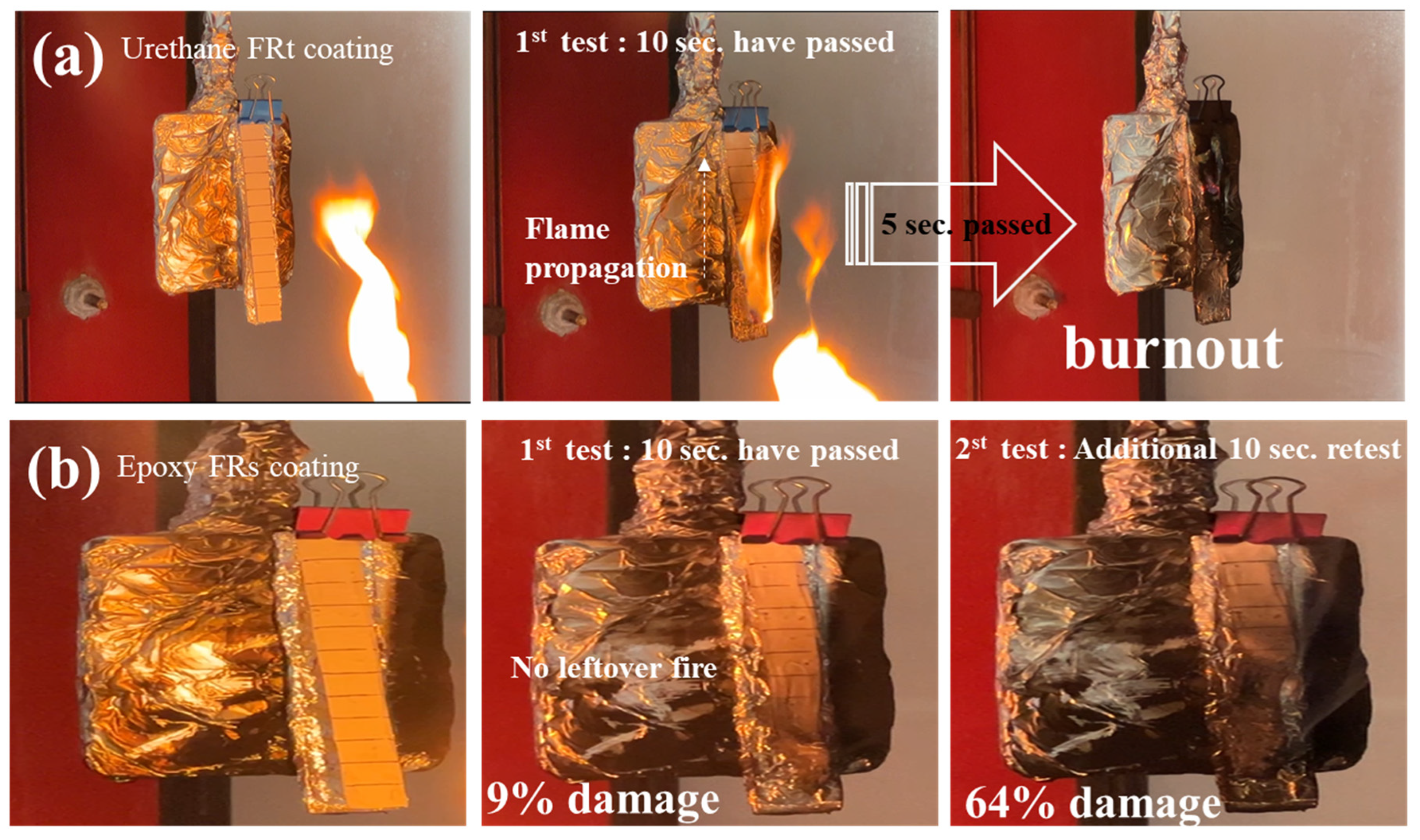
FRt and FRs coated specimens were installed in a combustion tester, and a high-temperature flame was irradiated on the specimen at a distance of 10 cm for 30 to 40 s using a burner. This experiment was repeated twice. Figure 2 shows a photograph of the change in the surface shape of the specimen before, during, and after the combustion tests. Figure 2a shows a urethane FRt coating specimen that was completely burned during the first test (10 s). Even after the torch’s flame was removed from the specimen, the residual fire remained on the back sheet. The fire continued spreading upward, and the fire fell. After the additional 5 s, the specimen completely burned out.
Figure 2. UL-94 test results of FRt- and FRs-coated specimens. (a) FRt coating: burnout in the first combustion test; (b) FRs coating: surface soot in the 1st test, 64% damaged in the second test.
Burner tests were performed on epoxy FRs specimens under the same conditions as shown in Figure 2b. In the first test, only 9% surface damage and some soot were observed. As soon as the burner fire was removed from the specimen, no leftover fires were observed. The second test was performed for an additional 10 s, and a 64% surface damage and soot were observed. However, no residual fire was observed at all. Compared to the FRt, the FRs coating revealed much better flame-blocking effects.

3.2.2. Cone-Calorimeter and NES 713 Test Results

In order to analyze the heat dissipation characteristics of the solar module and the FR coatings, calorimeter tests according to the ISO 5660-1 were performed. The cone calorimeter test can measure the heat release rate (HRR) and total heat release (THR) factors of the test piece exposed to radiant heat emitted from the cone-shaped heat irradiator with an ignition device attached. The combustion characteristics of the solar module were tested according to the conditions specified in the ISO 5660-1 []. According to the test conditions, the BIPV module specimen was manufactured with a size of 100 mm × 100 mm, the heat flux of the cone heater was 50 kW/m2, and the test time was 1800 s. It was intended to improve the reliability of the tests by performing three repetitions per test piece, and when analyzing the results of these tests, the average value for the three tests was used to manifest the tendency of fire and combustion characteristics.
In Figure 3a, all specimens reached the maximum HRR during the initial test interval (0~300 s) and then gradually decreased. Among the three specimens, the uncoated specimen (red) exhibited the highest HRR with two maximums of peaks. The first peak was reached before charcoal was formed near the combustion surface. The first heat release increased due to the combustion effect of the back sheet, and the heat release rate gradually decreased after the 350 kW/m2 peak value. The second peak is formed when a thermal wave reaches the back reinforced glass insulating layer. Due to the back effect of the insulating layer, the accumulated heat of Ethylene Vinyl Acetate (EVA) was instantly released. The max heat release rates of the RAW, FRt, and FRs specimens were measured as 350 kW/m2, 270 kW/m2, and 74 kW/m2, respectively. It was confirmed that the maximum heat release was reduced solely by the FR coating. In particular, the performance of FRs was superior. FRs reduced the heat release rate to 21% of that of RAW.
Figure 3. Time series heat release rate and total heat release obtained by cone calorimeter tests. (a) Heat release rate data and (b) total heat release data.
In Figure 3b, THR refers to the total amount of heat released due to the combustion of the test material. It is an important factor in the cone calorimeter test, and it was recognized as a significant test result in the case of ±10% difference of the THR value. The BIPV module used as an exterior material should meet the structural criteria to prevent fire diffusion. Thus, the flame-retardant material must have a total heat release of 8 MJ/m2 or less for 5 min after the test. As for the test piece satisfying as a flame-retardant material, only the FRs specimen satisfied the requirements.
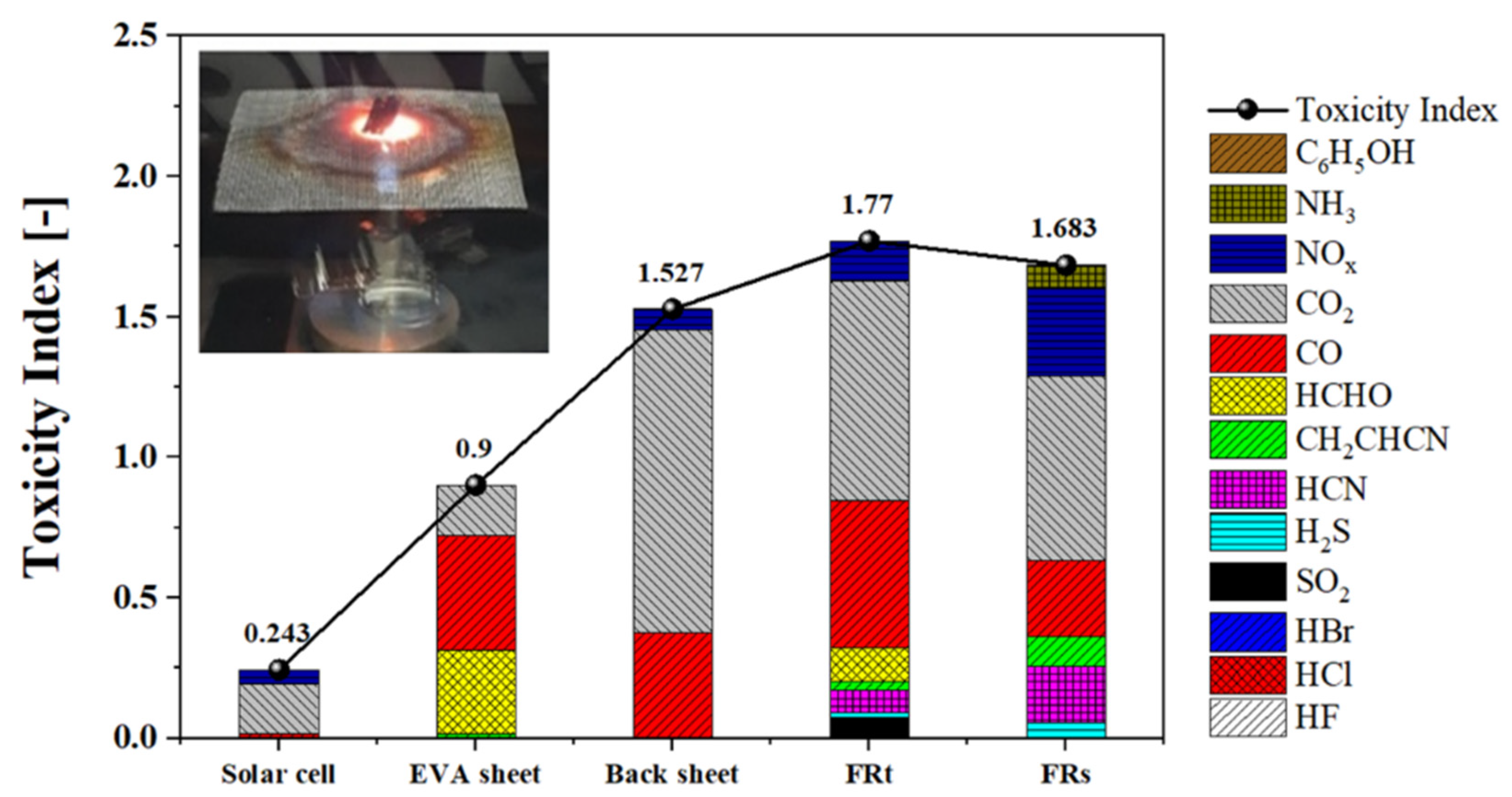
In order to analyze the change in the combustion products and the toxicity index of the solar module, the Toxicity Index Test according to the NES 713 was performed, as shown in Figure 4. The Naval Engineering Standard (NES) is a standard of the Royal Navy and is a test that calculates the toxicity index by measuring the type and amount of combustion products generated by burning 1g of the specimen inside a sealed chamber. By analyzing the toxicity index of harmful gases, it is possible to evaluate the risk of fire through the composition and lethal concentration of toxic gases during the combustion of combustible substances. Each test was conducted for each constituent material of the BIPV module, and an additional test was performed by coating the FR paint on the back sheet.
Figure 4. Toxicity index calculated by the NES 713 test data for thirteen toxic gases.
The temperature of the fire was kept constant in the chamber, and a small amount of the test piece was completely exposed to fire and burned for 90 s. Then, the fan was operated for 30 s to homogeneously mix the internal combustion gas. A total of 13 types of toxic gas concentrations were detected from a gas detection tube. The toxic gas concentration (Cg) was calculated by correcting the concentration diluted in the air in the chamber volume of 1 m3 when a test piece of 100 g was burned. The equation for gas concentration conversion is given in Equation (1):
C g = C i   × 100 × V   m
where Ci is the gas concentration (ppm), V is the volume of the chamber (m3), and m is the mass of the test piece (g) measured through the gas detection tube. The obtained Cg value is applied to the Toxicity Index calculation formula. Cf refers to the concentration (ppm) of toxic gas harmful to the human body when exposed to the gas for 30 min. In this study, 13 toxic gases, such as HF, were measured. The overall toxicity index (TI) was calculated using Equation (2):
T o x i c i t y   I n d e x = C g 1 C f 1 + C g 2 C f 2 +   +   C g 13 C f 13
Toxic concentration measurement tests were conducted on solar cells, EVA sheets, and back sheets without FR coating. After the test, soot was observed in the solar cell, and the electrical circuit board was completely damaged. EVA was melted when exposed to high-temperature flames. In the back sheet, the test piece caught fire within 5 s, and combustion proceeded very quickly. This is because PET (polyethylene terephthalate), a material of the back sheet, is a combustible polymer material that is easily burned. These combustible parts are considered unsuitable for use as building exterior materials.
Four HCHO, CO, CO2, and NOX gases were detected in solar cells, EVA sheet, and back sheet. CO and HCHO are produced due to incomplete combustion, and NOX is generated at a high temperature of about 1150 °C []. The results of measuring the toxicity index of all gases were found to be less than 2.0, with CO and CO2 accounting for the majority of the toxicity index. The total toxicity index value is 0.9~1.6 for the EVA sheet and back sheet, indicating that an exposure for 30 min can harm the human body. In the FRt-coated back sheet, various toxic gases were observed, and CO/CO2 accounted for most of the toxicity index. FRs had a toxicity index of 1.683, which was slightly lower than FRt. The toxicity index of FRt and FRs was higher than that of the solar cell and EVA, but it was comparable to that of the back sheet.

3.2.3. ISO 834 Test Results

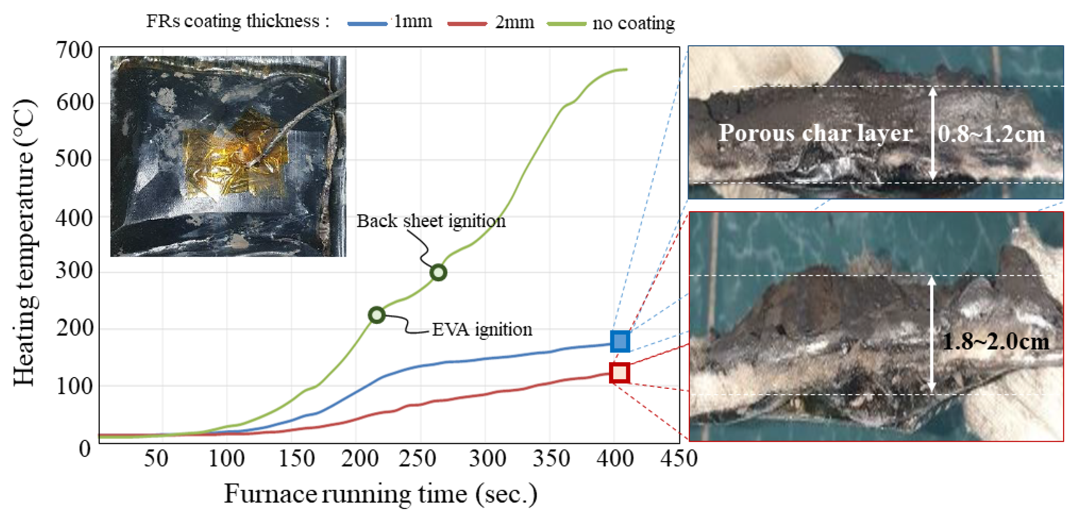
Using a large electric furnace, BIPV module specimens (RAW) and modules with FRs coating with 1 mm and 2 mm thickness were tested in the furnace. Figure 5 shows the heating temperature change as a function of time, as tested following the ISO 834. In the RAW specimen (green line), a fire occurred within 3 min after the start of the test. The heating temperature at the time of the fire was 300~400 °C. The flash points of EVA and PET, which are combustible materials of the solar module, were 260 °C and 346 °C, respectively. The FRt-coated specimen was tested, but a fire also occurred within 3 min. The FRt coating had no heat barrier effect at all.
Figure 5. Thermal blocking performance test results of FRs coating (by the ISO 834).
The FRs-coated module with a thickness of 1 mm (blue) was tested. The module was slightly deformed due to high-temperature heat, and the intumescent char layer was formed due to the expansion of the fire resistance coating on the side. The expanded carbonized layer thickness ranged from 0.8 to 1.2 cm. It was confirmed that the expanded thickness was about 10 times higher than that before the test. The FRs-coated module with a thickness of 2 mm also showed slight deformation, but no rim ignition. The porous layer was stably formed by the FRs coating expansion, and the adhesion between the module and the FRs coating was good. The expanded carbonized layer thickness was measured to be 1.8~2.0 cm.
It was concluded that the thicker the FRs, the thicker the carbonized film and the lower the temperature of the module. Seven minutes after the test, the temperature of the RAW was 600 °C or higher, but the temperature of the FRs-coated module was continuously maintained at 200 °C or lower. The difference in temperature measured between RAW and FRs was about 400 °C, and the heat shielding characteristics against fire were excellent even with a 1 mm FRs coating. These findings underscore the importance of coating thickness in determining the fire resistance of the BIPV module. The formation of a stable porous air layer and a carbonized film significantly enhanced thermal insulation and delayed ignition. The results demonstrate that even a 1 mm FR coating protects the fire efficiently. With increasing the thickness of FRs coating, the thermal barrier performance increased proportionally.

3.2.4. Additives’ Effect on Fire Resistance

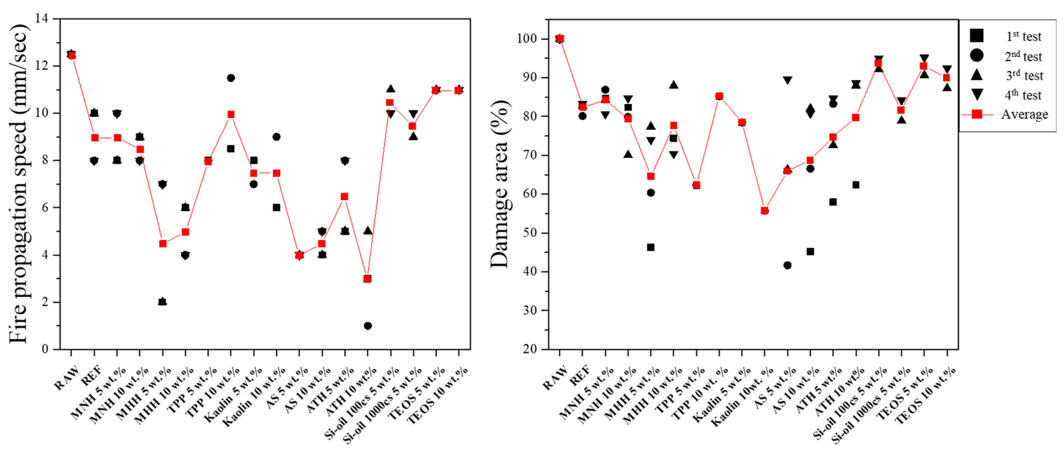
Since the epoxy-based FRs coating paint can be exhausted, additives are mixed with the acrylic FRs paint to improve fire resistance performance. Figure 6 shows the fire propagation rate on various specimens marked with symbols for RAW, specimens (REF) coated with FRs on the back sheet, and specimens showing components and concentrations of additional additives mixed with the FRs, where MNH is magnesium hydroxide, MHH is magnesium hexafluorosilicate hexahydrate, TPP is triphenol phosphate, AS is aluminum silicate, ATH is aluminum hydroxide, and TEOS is tetraethyl orthosilicate. A UL-94 tester was used to evaluate the flame-retardant performance of the samples coated by mixing additives in FRs paint. In Figure 6, the fire propagation rate of the back sheet specimen (RAW) was considerably faster, with 12.7 mm/s. In the REF specimen coated with only FRs, the flame propagation rate decreased to 9 mm/s. Among the additives, the effect of silicon oil, TEOS, and TPP was insufficient. It was evident that the fire propagation resistance was excellent in the modules added to ATH. As the ATH concentration was increased from 5 to 10%, the flame propagation rate further decreased.
Figure 6. Evaluation of flame resistance characteristics by additive components.
It was revealed that the propagation speed of the flame and the data for measuring the surface damage rate of the specimen were closely related to each other (Figure 6). In the RAW, 100% of the specimen was completely damaged in the first test, but the fire propagation speed was reduced by more than 50% (6.25 mm/s), and the damage rate was reduced by more than 20% in the aluminum-based ATH specimen. Among the additives, the oxide formation reaction of aluminum hydroxide into alumina is considered to have significantly contributed to reducing flame propagation. Silicon-based and titanium-based additives had relatively little effect on reducing the damage area. Overall, aluminum-based additives play a crucial role in forming a stable and heat-resistant barrier, enhancing the flame-retardant properties and improving the structural stability of the coating layer under extreme heat conditions.

3.3. Mechanism for FRt Coating Modes of Action with ATH

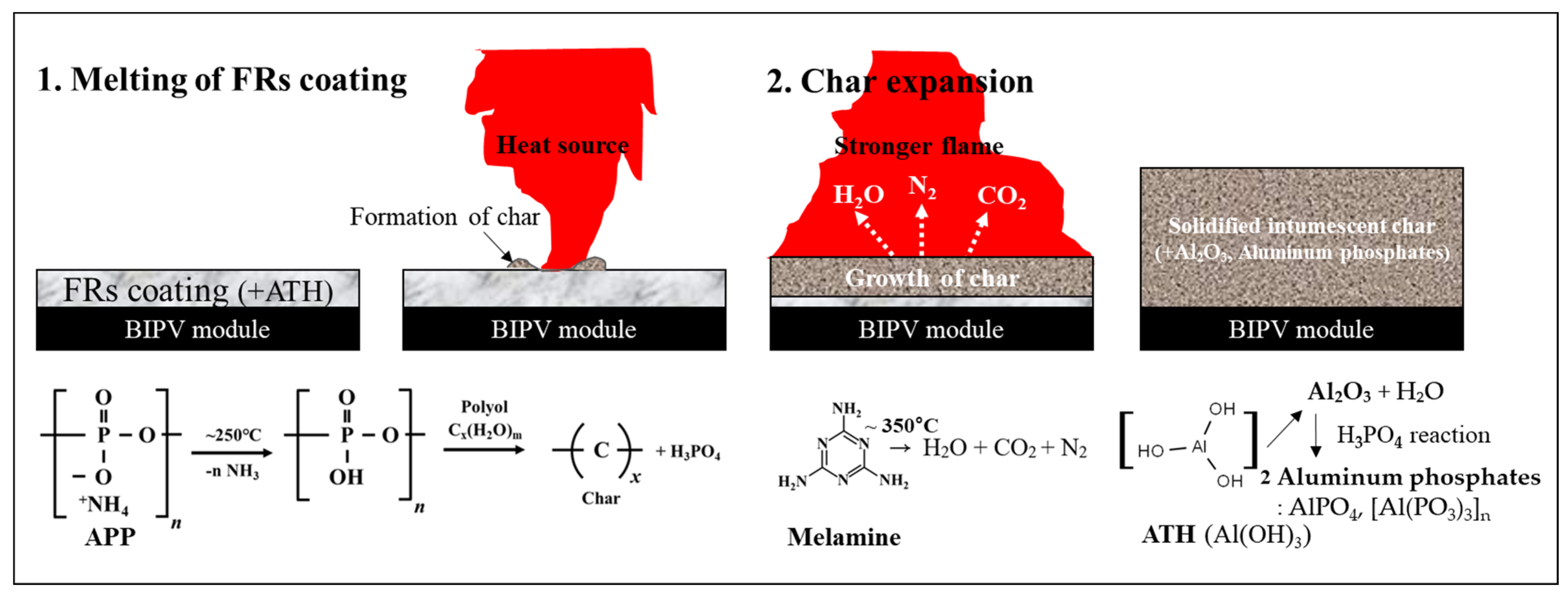
Figure 7 illustrates the conceptual diagram of the reaction mechanism of the FRs coating layer with ATH additives applied to the BIPV module. The chemical reaction of the FR coating and its mechanisms for effectively suppressing fire propagation in solar panels under a combustion environment are as follows:
Figure 7. Mechanism for combustion and fire-resistant coating modes of action with ATH.
-
Step 1: When the FR-coated solar module is exposed to flames, the FR coating layer expands to form a porous ceramic multilayer structure, including a carbonized char layer and an oxide layer on the surface, creating a heat-shielding layer with extremely low thermal conductivity. As the temperature of the FR coating layer rises due to the flame and reaches approximately 250 °C, APP begins to decompose, initiating a gas expansion reaction driven by melamine. APP consists of polyphosphate chains formed through the condensation of ammonium ions and phosphate molecules. At around 250 °C, it decomposes to release phosphoric acid, which then combines with polyol to form a char that acts as a physical protective layer.
-
Step 2: The expansion of the char formed by melamine decomposition is activated. As the internal temperature of the FR coating layer reaches approximately 350 °C, melamine releases a significant amount of expandable gases (CO2, N2), promoting the expansion and foaming of the carbonized layer. The nitrogen and carbon dioxide gases released from melamine decomposition expand the char into a porous form, forming a porous heat-shielding layer that effectively protects the module from high-temperature flames.
-
Step 3: Aluminum hydroxide is decomposed into Al2O3 and H2O. At this stage, some Al2O3 reacts with phosphoric acid to form thermally stable aluminum phosphate compounds, such as AlPO4 and [Al(PO3)3]ₙ.

3.4. Adhesion Properties Between the Coated Layer and the Substrate

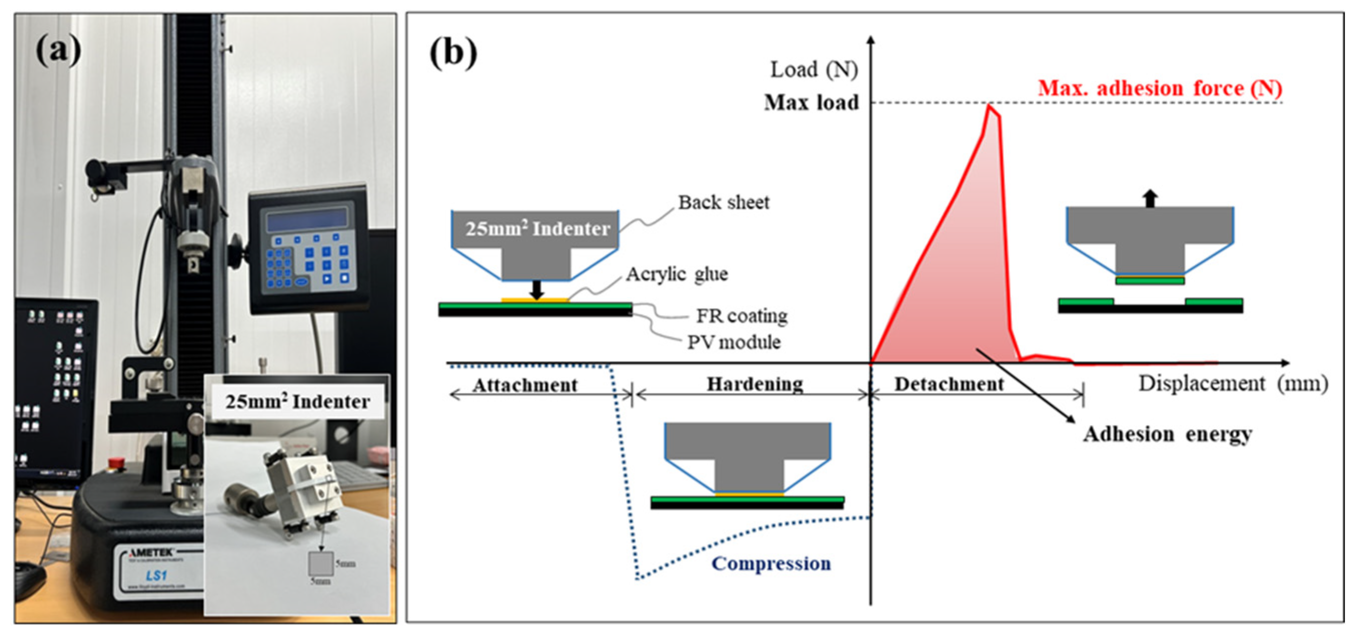
Figure 8 presents the testing machine and methods to evaluate adhesion properties between the coated layer and the substrate. The tack test can analyze the magnitude of the force measured on the load cell against a displacement. The maximum attachment force (adhesion strength) was defined by the maximum load value, and the adhesion energy is defined by the area under the curve of load vs. displacement. The retention time of the attachment step is 600 s, the pressing speed is 6 mm/min, the pressing force is 5 N, and the detachment speed is 20 mm/min.
Figure 8. Evaluation of adhesion properties between the FR coating and the substrate. (a) Tensile tester and indenter; (b) schematics to describe the adhesion force and energy.
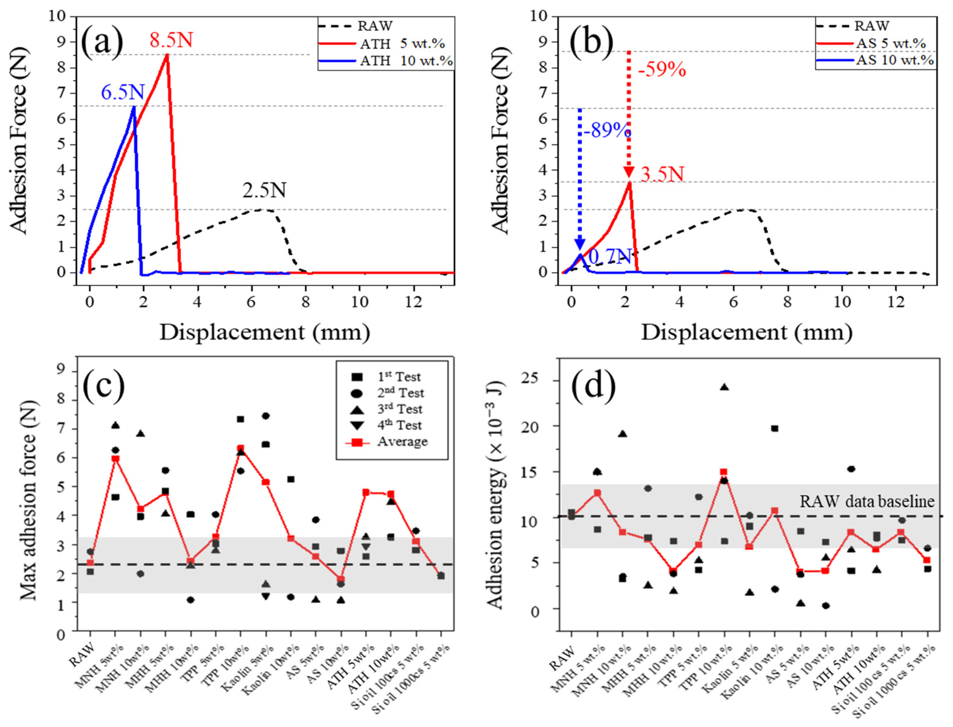
Figure 9 shows adhesion strength and adhesion energy by the application of various additives. With the 5% ATH addition (thickness 1mm), the maximum adhesive force of 8.5 N was observed, but it reduced to 6.5 N in the 10% ATH addition (Figure 9a). The improvement of adhesion strength with the addition of ATH is attributed to the synergy effect between the OH ion in the additive ATH and the OH ion in the acrylic resin. On the other hand, AS, a similar aluminum series, had very little effect on the adhesion improvement (Figure 9b). The measurement results for the other additives are presented in Figure 9c,d. It was found that the maximum adhesive force increased when MNH, TPP, kaolin, and ATH were mixed with the FRs. In the specimen mixed with 10 wt% TPP and 5 wt% kaolin, adhesion strength improved more than 5 N, whereas most silicon-based materials tended to decrease. The average adhesive energy was in the range of 5~15 (×10−3 J), and it varies depending on the types and amounts of additives.
Figure 9. Analysis of adhesion performance by various additives. (a) Adhesion force of ATH, (b) AS, (c) max adhesion force, and (d) adhesion energy.

3.5. Comparison of Cost-Effectiveness Among the Additives

The performance indicators for the additives can be derived by considering the fire/flame resistance and adhesion properties obtained through experiments, as well as workability and cost among the additives. In this work, the fire resistance performance of coating materials was evaluated using several key parameters based on experimental results from the UL-94 test and the burn test, as defined in Equation (3):
F i r e   r e s i s t a n c e   i n d e x = α × 1 a + β × 1 b + γ × 1 c + δ × ln d + 10 3 + ε × ln e + 10 3
a: flame spread (mm/s)
b: the percentage of damaged area (%)
c: the percentage of flame spread area on the surface (%)
d: the remaining combustion duration (seconds)
e: the percentage of the sample area melted (%)
α, β, γ, δ, and ε: constants
The superior adhesion properties between the FRs coating and the BIPV module can be estimated from the low flame propagation speed and the high fire-shielding capability. Paint workability can also be evaluated based on various indicators such as the viscosity of paint, drying time, the compatibility with application tools (brush, roller, spray equipment, etc.). The evaluation data of each additive classified by these performance indicators are summarized in Table 4.
Table 4. Comparison of cost-effectiveness among the additives.
In terms of cost-effectiveness, AS and ATH were the most effective among the additives. AS has high thermal stability, which greatly improves the fire resistance of the coating by maintaining the structure at high temperatures and forming a physical barrier. It also has low thermal conductivity and thus blocks heat transfer throughout the coating, which slows down the temperature rise on the coating surface and delays the spread of fire. Moreover, AS improves the mechanical strength of the coating, increasing the resistance to physical impact and wear, thereby enhancing the overall durability of the coating.
On the other hand, ATH not only releases H2O during thermal decomposition to absorb heat but also dilutes combustible gases to suppress the combustion process and enhance flame-retardancy. Water vapor released during the decomposition also suppresses the formation of smoke, reducing the emission of toxic gases in the case of fire. ATH also acts as a protective barrier by forming stably porous carbides when exposed to high temperatures, and further strengthens fire resistance by preventing outside oxygen from diffusing into the interior. The high heat capacity of alumina (Al2O3) products contributes to the thermal stability of the coating and enables it to maintain its protective properties under high temperature conditions. By understanding and utilizing these mechanisms, it is expected that the integration of AS and ATH into the fire-resistant coating could be an effective method for the fire safety of the BIPV modules.

4. Conclusions

This work investigates the possibility of suppressing and preventing fire proliferation and damage in the BIPV module, as well as improving the fire safety performance of the FR coating. Main findings are summarized below:
(1)
An epoxy-based FRs coating applied to the module showed better overall performance than a urethane-based FRt coating. Surface damage, such as cracks and blisters, was observed for the FRt coating during the impact and acid resistance tests, but the FRs coating showed better durability without any defects.
(2)
In the UL-94 test, FRt was completely burned within 10 s in a combustion environment, whereas FRs maintained its intact condition. The damage rate of FRt was 100%, while that of FRs was only 9%.
(3)
In cone calorimeter tests, the maximum HRS of the three specimens, RAW, FRt, and FRs, were measured as 350 kW, 270 kW, and 74 kW, respectively. It was confirmed that the heat release was reduced solely by the FR coating. In particular, the performance of FRs was superior. FRs reduced the heat release rate to 21% of that of RAW.
(4)
In the ISO 834 test, the FRs-coated specimen demonstrated significantly enhanced thermal shielding performance compared to the RAW specimen. After 400 s, the temperature of the RAW specimen reached 680 °C, whereas the temperature of the FRs specimen remained below 200 °C. Even with just a 1 mm FRs coating, more than 70% of the heat can be blocked.
(5)
ATH manifested the most cost-effective flame-retardant characteristics among the additives. The fire propagation rate of the ATH additive was reduced by 83%, and the adhesion strength was approximately 3.4 times higher than the specimen without FR coating.

Author Contributions

Conceptualization, M.J.S.; validation, Y.C.J.; formal analysis, H.K.P.; investigation, M.J.S. and H.K.P.; data curation, M.C.L.; writing—original draft preparation, Y.C.J.; writing—review and editing, M.C.L. and S.Y.L.; supervision, S.Y.L.; project administration, S.Y.L. All authors have read and agreed to the published version of the manuscript.

Funding

This research was funded by [National Research Foundation of Korea] grant number [RS-2024-00398068] and [RS-2023-NR077179].

Data Availability Statement

The original contributions presented in this study are included in the article. Further inquiries can be directed to the corresponding author(s).

Acknowledgments

This work was supported by Korea Electric Power Corporation, National Research Foundation (NRF) and the Korean government.

Conflicts of Interest

The authors declare no conflict of interest.

References

  1. Deng, Q.; Zhang, B.; Zhou, Z.; Deng, H.; Zhou, L.; Zhou, Z.; Jiang, H. Evacuation time estimation model in large buildings based on individual characteristics and real-time congestion situation of evacuation exit. Fire 2022, 5, 204. [Google Scholar] [CrossRef]
  2. Proulx, G. Evacuation time and movement in apartment buildings. Fire Saf. J. 1995, 24, 229–246. [Google Scholar] [CrossRef]
  3. National Fire Data System. Current Status of Fire in Building. Available online: https://www.nfa.go.kr/nfa/safetyinfo/residentialfire/present/ (accessed on 10 October 2024).
  4. Korea Fire Protection Association (KFPA). Building Fire Occurrence Trend. Available online: https://www.kfpa.or.kr/webzine/202408/disaster7.html (accessed on 10 October 2024).
  5. National Index. Fire Occurrence Trend. Available online: https://www.index.go.kr/unity/potal/main/EachDtlPageDetail.do?idx_cd=1632 (accessed on 10 October 2024).
  6. Aram, M.; Zhang, X.; Qi, D.; Ko, Y. A state-of-the-art review of fire safety of photovoltaic systems in buildings. J. Clean. Prod. 2021, 308, 127239. [Google Scholar] [CrossRef]
  7. Aram, M. Fire Smoke Control for Building Integrated Photovoltaic (BIPV). ASHRAE Trans. 2021, 127, 14–16. [Google Scholar]
  8. Meacham, B.; McNamee, M. Fire Safety Challenges of ‘Green’ Buildings and Attributes. Available online: https://www.ashb.com/wp-content/uploads/2021/03/IS-2021-68.pdf (accessed on 10 October 2024).
  9. Miao, L.; Chow, C.L. Investigation of burning photovoltaic panels on a double-skin facade with ejecting flame from an adjacent room fire. Indoor Built Environ. 2019, 28, 938–949. [Google Scholar] [CrossRef]
  10. Wu, Z.; Hu, Y.; Wen, J.X.; Zhou, F.; Ye, X. A review for solar panel fire accident prevention in large-scale PV applications. IEEE Access 2020, 8, 132466–132480. [Google Scholar] [CrossRef]
  11. Ministry of Land, Infrastructure and Transport (MOLIT). Building Act, Article 49, Evacuation of the Building and Restrictions; Law No. 9437; Ministry of Land, Infrastructure and Transport (MOLIT): Sejong City, Republic of Korea, 2009.
  12. Proulx, G.; Fahy, R.F. The time delay to start evacuation: Review of five case studies. Fire Saf. Sci. 1997, 5, 783–794. [Google Scholar] [CrossRef]
  13. Jimenez, M.; Duquesne, S.; Bourbigot, S. Characterization of the performance of an intumescent fire protective coating. Surf. Coat. Technol. 2006, 201, 979–987. [Google Scholar] [CrossRef]
  14. Mariappan, T. Recent developments of intumescent fire protection coatings for structural steel: A review. J. Fire Sci. 2016, 34, 120–163. [Google Scholar] [CrossRef]
  15. Oktokkian. BIPV Product Description. Available online: http://oktokkiam.com/html/sub02/sub02_0203.php (accessed on 10 October 2024).
  16. UL 94; Tests for Flammablity of Plastic Materials for Parts in Devices and Appliances. UL Solutions: Chicago, IL, USA, 2023.
  17. Gao, M.; Wang, J.; Cong, C.; Ma, C.; Morshed, M.; Wang, Z. Degradation of epoxy coatings cooperated with polyaniline nanowires in the outdoor environment. Polym. Adv. Technol. 2021, 32, 988–999. [Google Scholar] [CrossRef]
  18. Liu, F.; Yin, M.; Xiong, B.; Zheng, F.; Mao, W.; Chen, Z.; Fang, P. Evolution of microstructure of epoxy coating during UV degradation progress studied by slow positron annihilation spectroscopy and electrochemical impedance spectroscopy. Electrochim. Acta 2014, 133, 283–293. [Google Scholar] [CrossRef]
  19. Maibohm, C.; Brewer, J.R.; Sturm, H.; Balzer, F.; Rubahn, H.G. Bleaching and coating of organic nanofibers. J. Appl. Phys. 2006, 100, 054307. [Google Scholar] [CrossRef]
  20. Gökçe, C. UV Aging of Epoxy Fiber Composite. Bachelor’s Thesis, Arcada University of Applied Sciences, Helsinki, Finland, 2020. [Google Scholar]
  21. Shi, X.; Croll, S.G. Thermal-induced recovery of small deformations and degradation defects on epoxy coating surface. J. Coat. Technol. Res. 2010, 7, 73–84. [Google Scholar] [CrossRef]
  22. Al-Dulaymi, S.A.A.; Brown, T.; Fellows, C.; Mahini, S.S. Prevention of environmental degradation of epoxy resins modified with the addition of different fillers. Ph.D. Thesis, University of New England, Biddeford, ME, USA, 2019. [Google Scholar]
  23. Jiang, H.; Browning, R.; Liu, P.; Chang, T.A.; Sue, H.J. Determination of epoxy coating wet-adhesive strength using a standardized ASTM/ISO scratch test. J. Coat. Technol. Res. 2011, 8, 255–263. [Google Scholar] [CrossRef]
  24. ISO 834-11:2014; Fire Resistance Tests—Elements of Building Construction—Part 11: Specific Requirements for the Assessment of Fire Protection to Structural Steel Elements. International Organization for Standardization: Geneva Switerland, 2014.
  25. ISO 4892-2:2013; Plastics—Methods of Exposure to Laboratory Light Sources—Part 2: Xenon-arc Lamps. International Organization for Standardization: Geneva Switerland, 2013.
  26. KS M ISO2812-1; Paints and Varnishes—Determination of Resistance to Liquids—Part 1: Immersion in Liquids Other Than Water. Korea Agency for Technology and Standards: Sejong, Republic of Korea, 2022.
  27. KS D 3520:2018; Prepainted Hot-Dip Zinc-Coated Steel Sheets and Coils. Korea Agency for Technology and Standards: Sejong, Republic of Korea, 2020.
  28. ASTM D4060-14; Standard Test Method for Abrasion Resistance of Organic Coatings by the Taber Abraser. ASTM International: West Conshohocken, PA, USA, 2019.
  29. NES 713; Determination of the Toxicity Index of the Products of Combustion from Small Specimens of Materials. Ministry of Defence: London, UK, 1982.
  30. ASTM D 6195; Standard Test Methods for Loop Tack. ASTM International: West Conshohocken, PA, USA, 2019.
  31. ISO 5660-1:2015; Reaction to Fire Tests—Heat Release, Smoke Production and Mass Loss Rate. Part 1: Heat Release Rate (Cone Calorimeter Method) and Smoke Production Rate (Dynamic Measurement). International Organization for Standardization: Geneva, Switzerland, 2015.
  32. Russell, A.T. Combustion emissions. In Air Pollution and Cancer; Springer: Berlin, Germany, 2013; Volume 161. [Google Scholar]
Disclaimer/Publisher’s Note: The statements, opinions and data contained in all publications are solely those of the individual author(s) and contributor(s) and not of MDPI and/or the editor(s). MDPI and/or the editor(s) disclaim responsibility for any injury to people or property resulting from any ideas, methods, instructions or products referred to in the content.

Article Metrics

Citations

Article Access Statistics

Multiple requests from the same IP address are counted as one view.