1. Introduction
As fossil fuel reserves are continuously decreased and the effects of climate change become more obvious, the challenge of passing from conventional energy sources to renewable ones, such as hydrogen, becomes more relevant. The growing energy demand and the need to reduce emissions of environmentally harmful greenhouse gases requires the search for new clean and sustainable alternative energy sources [
1]. In this regard, hydrogen has become an important fuel and energy resource to move from traditional fuel energy to “green” energy. Hydrogen is considered a potentially profitable fuel because it is the most abundant element on Earth, it has the highest specific energy, and, in addition, the product of the combustion of hydrogen is the environmentally friendly water [
2]. Thus, hydrogen fuel is a clean source of energy, with no adverse environmental impact during operation because its byproducts are heat and water. In addition, it is more efficient than many other energy sources. However, hydrogen fuel has a number of disadvantages relative to other energy sources, which include safety concerns as hydrogen is a highly flammable fuel and difficulties in storage and transportation, which are rather complex and imply additional costs. Apart from that, despite being the most abundant element, hydrogen is a secondary source of energy, so it needs to be obtained from different primary sources, for instance, from water via electrolysis, which requires a significant amount of energy [
1]. Nevertheless, despite such disadvantages, hydrogen is an environmentally friendly alternative to fossil fuels and is widely used in fuel cells to produce energy.
In order to convert the heat of combustion of hydrogen into electrical energy, electrochemical conversion devices, such as fuel cells, are required [
3]. Fuel cells (FCs), and solid oxide fuel cells (SOFCs) in particular, are the most widely used electrochemical devices capable of converting the chemical energy of a fuel, including hydrogen, directly into electricity and heat. They are among the most promising types of fuel cells due to their highest efficiency and versatility [
4]. A single fuel cell consists of a cathode and an anode separated by a solid electrolyte, as shown in
Figure 1.
Hydrogen-containing fuel is fed to the anode, while oxygen-containing air is fed to the cathode. At the anode side, hydrogen is oxidized to form protons and the electrons generated during the oxidation of the fuel at the anode are accepted at the cathode to reduce oxygen, thus completing the external circuit. The resulting O
2− ions selectively pass through the electrolyte to the three-phase anode/electrolyte interface, where the protons combine with oxygen ions to form water. Thus, electricity is produced by the flow of electrons in the external circuit [
5]. Currently, one of the key factors limiting the commercialization of SOFCs is the difficult manufacturing process. Traditional methods, such as casting and sputtering, do not provide the necessary control over the thickness and composition of the layer, while precision methods, such as vapor deposition, are too expensive to be commercially viable [
3]. Therefore, the development of new, cost- and time-efficient methods to produce both SOFCs and their individual elements is required [
6].
In recent years, 3D printing technologies for the fabrication of functional devices, including SOFC elements, have developed significantly [
7,
8]. Inkjet printing based on digital, non-contact pattern formation by applying inks or pastes on a substrate is of particular interest as a method of manufacturing SOFCs and their individual components [
9]. Three-dimensional printing is a high-resolution method, allowing precise control of the microstructure of the SOFC functional layers [
10]. The thickness and microstructure of the layers can be controlled by varying the rheological parameters of the compositions for 3D printing, which in turn depend on both the size distribution of the solid filler and the viscosity and surface tension of the polymer binder [
9]. In addition, a wide range of inkjet printers, from small and inexpensive lab/R & D to industrial/production models, is currently available on the market.
Recently, the use of inkjet printing to produce SOFC electrodes and electrolytes, as well as a complete SOFC, has been reported in several studies. Thus, 3D inkjet printing was implemented for the production of a La
xSr
1−xCo
yFe
1−yO
3−δ cathode [
11]. Due to the increase in the three-phase boundary, a significant reduction in the polarization resistance values and a maximum power output enhancement of 25% occurred. In one study [
12], a planar electrolyte based on yttria-stabilized zirconia (YSZ) with a thickness of 23 μm was printed and sintered, and a current density of 0.7 A/cm
2 was achieved when a symmetrical Ni-YSZ|YSZ|YSZ-LSM|LSM cell, where LSM is lanthanum strontium manganite, was used as an electrolyzer. In another study [
13], a functional NiO/YSZ anode layer, an YSZ electrolyte layer, and LSM-YSZ and LSM cathode layers were deposited onto a NiO–YSZ carrier substrate using inkjet printing. The printed element, when tested in hydrogen, gave a stable voltage of 1.1 V and a maximum specific power of 0.46 W/cm
2 at 850 °C. In a different study [
14], a highly conformal 6–12 μm thick and dense YSZ electrolyte layer; a functional, porous NiO/YSZ anode layer; and a porous anode-interlayer were produced using inkjet printing. Open circuit voltages ranged from 0.95 to 1.06 V and a maximum power density of 0.175 W/cm
2 was achieved at 750 °C.
Although there are a sufficient number of studies on printing of both individual elements (electrolyte, cathode) of SOFCs and several functional layers simultaneously, at present there is a limited number of studies on printing of anode-supported SOFCs. However, this task is relevant, since nowadays, when developing SOFCs, preference is given to anode-supported fuel cells. This is due to the better electrical conductivity of the anode material during reduction, while low ohmic losses contribute to a reduction in the SOFC operating temperatures, thus enabling higher performance. Lower operating temperatures reduce degradation of the cell, thereby increasing its lifetime [
15]. Until now, 3D printing of supporting anodes for SOFCs has not yet been reported, while 3D electrolyte structures have already been fabricated by inkjet printing [
12]. However, the electrolyte should be dense and gas-tight, while the anode should be porous; therefore, the techniques and approaches used for the fabrication of dense and gas-tight electrolytes by 3D printing are not suitable for fabricating anodes. For this reason, in order to apply the 3D printing method to the preparation of anodes, new approaches need to be explored and developed.
In this work, a layer-by-layer approach to fabricate the anode support by inkjet printing followed by layer-by-layer selective laser treatment was carried out [
16]. Laser post-treatment of the printed layers helped to remove the organic additives from the printing compositions. The latter significantly reduces the shrinkage of the anode during thermal sintering and makes it possible to obtain a sample geometrically even in shape with a specified microstructure. NiO/YSZ, one of the most used composites for medium-temperature SOFCs with an operating temperature of 750–850 °C, was used as the material for the SOFC anode [
17]. During operation, this ceramic composite is reduced to Ni/YSZ cermet, which has high electronic conductivity and high catalytic activity in reform reactions. YSZ acts as a matrix for nickel oxide particles, preventing their coalescence and the anode transformation from ceramic to cermet during the SOFC operation. Apart from that, the addition of YSZ equalizes the thermal expansion coefficients of the anode and electrolyte, thus preventing cracking and flaking of the fuel cell during fabrication and operation [
18].
To the best of our knowledge, this hybrid, additive, layer-by-layer manufacturing process to build ceramics has not been used before. The features and capabilities of this method that allows control of microstructure and porosity of the resulting ceramic parts were first studied here. Our approach has never before been used for the fabrication of complete SOFCs and their individual components.
2. Materials and Methods
Nickel(II) oxide (≥99.5%, SOFCMAN, Ningbo, China), yttria-stabilized zirconia 10 mol% (YSZ10) (Neohim LLC, Moscow, Russia), dipropylene glycol monobutyl ether (DPGBE) (Sigma-Aldrich, St. Louis, MO, USA), polyvinyl butyral (PVB) (Acros Organics, Antwerp, Belgium), dibutyl phthalate (DBP) (Sigma-Aldrich, St. Louis, MO, USA), and graphite (Sigma-Aldrich, St. Louis, MO, USA) were used as received without further purification.
To prepare the NiO/YSZ10 (60:40) composite material, nickel(II) oxide and YSZ10 were milled and homogenized in a laboratory submerged ball mill (VMA-Getzmann, Reichshof, Germany) using yttria-stabilized zirconia YSZ8 balls (dballs = 1.2 mm). The powders were ball-milled and homogenized in ethanol for 1 h at 5000 rpm and at a powder:ethanol:balls volume ratio of 1:1.5:2. The as-prepared slurry was kept in a drying box at 80 °C until completely dry.
For the synthesis of pastes, PVB and DBP were dissolved in DPGBE under stirring at 70 °C. The mixture (organic binder) was then placed in a laboratory submerged ball mill with yttria-stabilized zirconia YSZ8 balls (dballs = 0.6 mm) followed by the addition of NiO and YSZ10 powders (60/40 wt.%) to the mixture, which was dispersed at 5000 rpm for 2 h; then, the paste was separated from the milling balls. To prepare the paste with a pore former, the NiO and YSZ10 powders were dispersed in the organic binder for 1.5 h at 5000 rpm, then the speed was reduced to 1000 rpm and pore former graphite was added to the suspension followed by stirring for 0.5 h. The pastes were analyzed for suspended solids content. For this purpose, a weighed sample was heated to 270 °C to remove the solvent and then it was weighed again. The weight loss yielded the original solids content.
The printing of NiO/YSZ anodes was carried out using a hybrid laboratory inkjet 3D printer with the option of laser post-treatment of the layers. In order to control the layer thickness and the shape of the final sample, the printer was equipped with various dispensing systems for low-viscosity and high-viscosity compositions [
16]. All the printing experiments were carried out using a pneumatic pulse valve with a nozzle diameter of 0.25 mm (Nordson Corporation, Westlake, OH, USA). Laser sintering of the printed layers using a fiber laser operating at a wavelength of 1.064 μm in a pulsed-intermittent mode was carried out in single-pass mode with variable laser power. The duration and frequency of the laser pulse were 4 ns and 250 kHz respectively; the average power varied in the range of 0.45–2.7 W. The printed samples were sintered at a temperature of 1400 °C for 2 h. The general scheme of the fabrication of anodes by hybrid 3D printing is shown in
Figure 2.
X-ray diffraction patterns (XRD) of the samples were recorded using a DS Advance powder X-ray diffractometer (Bruker, Karlsruhe, Germany) equipped with a 1D Lynx-Eye detector and Ni-filtered CuKα radiation (0.02° 2θ step size, an accumulated time per step of 0.2 s, survey time range from 15 to 80°). Quantitative phase analysis was conducted by the Rietveld method [
19] using Topas 4.2 software (Bruker AXS, Karlsruhe, Germany) for the profile and structural analysis. The morphology of the samples was analyzed using a Hitachi 3400 N scanning electron microscope (Hitachi, Tokyo, Japan). The paste viscosity was measured using a Brookfield DV3T-RV viscosimeter (Brookfield Engineering Labs, Middleborough, MA, USA) with the cone/plate geometry at 25 °C. The granulometric composition of the samples was analyzed using a SALD-7500nano laser particle analyzer (SHIMADZU Corporation, Kyodo City, Japan). The contents of the pores in the sample were determined by means of ImageJ software using SEM images. The curves of differential thermal analysis (DTA) and the change in the sample mass (TG) were obtained using a STA 449F1 Jupiter synchronous thermal analyzer (NETZSCH, Selb, Germany). The printed sample was heated to 1000 °C in an atmosphere of O
2/Ar (0.2/0.8) at a rate of 5 °C/min.
3. Results and Discussion
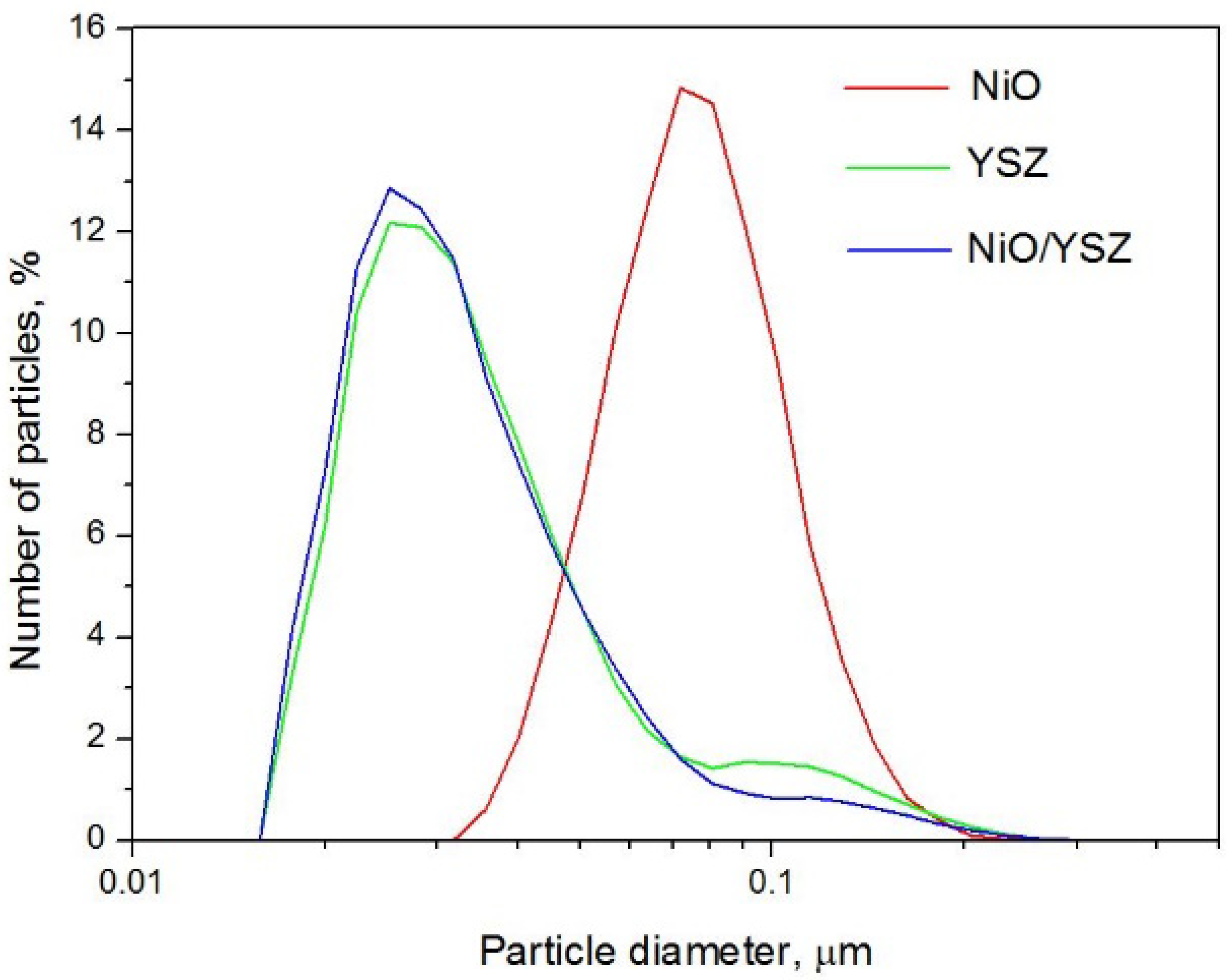
Figure 3 shows the particle size distribution of the initial YSZ10 and NiO powders and the NiO/YSZ composite obtained after milling and homogenization. As seen, the initial NiO and YSZ powders show a monomodal size distribution; for NiO, the peak is at 0.8 µm, and for YSZ10, it is at 0.28 µm. After ball milling, the histograms of pure YSZ10 and the resulting NiO/YSZ composite almost coincide. Therefore, it can be concluded that when preparing the ceramics in a ball mill, mostly nickel oxide is ground, while YSZ remains unchanged.
Using the NiO/YSZ composite so obtained, two types of pastes for inkjet printing were prepared, one in the presence and one in the absence of a pore former. The optimal paste composition would meet the following requirements: solid-phase concentration ≤60 wt%, viscosity in the range 150–300 mPa·s, particle size with a percentile score of D50 ≤ 3 mm [
20]. The components for the paste binders were chosen according to the above criteria. PVB is characterized by great adhesive, optical, and film-forming properties, good physical and mechanical properties, as well as good plasticity and wear resistance [
10]. DBF is a well-known plasticizer that increases the resistance of the printed pattern to mechanical stress and prevents cracking [
21].
In order to determine the optimal mass content of the NiO/YSZ composite in the paste, its stability, depending on the composite loading, was studied. To this end, after milling and homogenization, the pastes were kept for three days and then they were analyzed for suspended solids content by the gravimetric method. The results showed that in the case of paste with a composite loading of ≥60 wt.%, after being exposed for three days, the suspended solids content was more than 90% of the loaded mass, which is a satisfactory result (
Table 1). The data are in good agreement with the requirements for ceramic pastes for 3D printing [
20].
Viscosities of the as-prepared composite-based pastes were shown to be suitable for inkjet 3D printing [
18]. As seen from
Figure 4, an increase in the mass content of the filler in the paste results in an increase in the value of dynamic viscosity of the pastes. The nonlinear dependence of the dynamic viscosity on the shear rate suggests that the pastes are non-Newtonian fluids (
Figure 4).
Based on the printing tests carried out at different frequencies and print head valve opening times, the optimum mode for inkjet printing of 3D objects was selected. Thus, a valve opening frequency of 20 Hz and a valve opening time of 700 ms were considered to be optimal for printing patterns using the as-prepared paste.
Figure 5 shows the drops printed in this mode. As seen, small droplets that were perfectly spherical in shape and without satellites were obtained. The size distribution of the droplets demonstrates that the droplet size is reproduced quite accurately, which allows future precision printing of anode supports for SOFCs.
The method of 3D inkjet printing combined with laser post-treatment presented in this paper provides a unique opportunity to print samples of various shapes and thicknesses. Laser post-treatment makes it possible to create the final shape of an object by partially removing the organic binder, while the use of printing compositions with a wide range of rheological characteristics allows precise control of the shape and the thickness of the layer.
Figure 6 shows the as-printed NiO/YSZ anodes which are circular planar and rectangular planar in shape after sintering at 1400 °C.
The process of removing the organic binder from the paste during thermal annealing was studied by DTA/TG analysis (
Figure 7). The thermogravimetric curve shows that the main weight loss of the sample occurs in the temperature range of 80 to 200 °C, which can be related to the evaporation of the solvent from the printing composition. An endothermic peak observed in the DTA curve in the same temperature range confirms this assumption. A further weight loss of 2.5 wt.% in the temperature range of 200 to 380 °C can be attributed to binder burnout of the PVB polymer. An exothermic peak observed in the DTA curve in the same temperature range also indicates an ongoing burnout process. The total weight loss of the sample is equal to ≈40 wt.%; consequently, the residual product content is ≈60 wt.%, which is in accordance with the mass content of the NiO/YSZ composite in the initial printing composition.
The effect of layer-by-layer laser treatment on the morphology of the sample surface was studied.
Figure 8 shows a photograph of printed anode samples at various laser exposures. The anodes in the figure are arranged from left to right in order of increasing exposure value from 0 to 14.1 J/cm
2. As can be seen, due to layer-by-layer laser treatment, the organic binder is partially removed resulting in the formation of the final shape of the sample. An increase in the value of laser exposure decreases the content of the organic binder in the sample. However, at an exposure value of 14.1 J/cm
2, the edges of the sample begin to bend and the anode support is deformed.
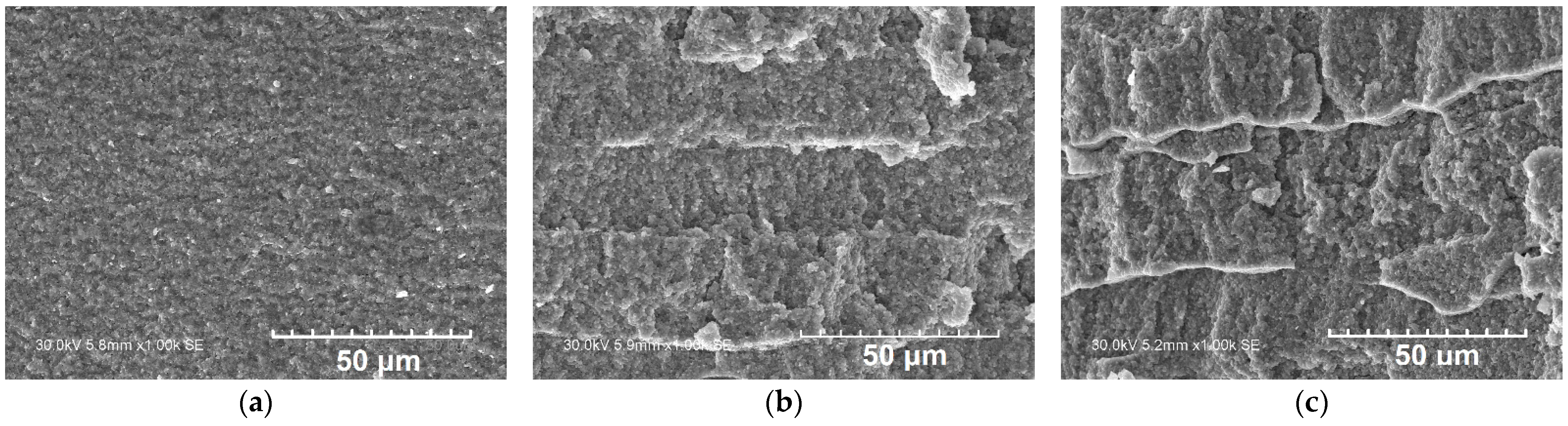
The SEM images of the cross sections of the NiO/YSZ anode after printing with layer-by-layer laser treatment at various laser exposure values followed by sintering of the sample are shown in
Figure 9. As can be seen, in the absence of layer-by-layer laser treatment, the anode has a monolithic, low-porous structure. When using layer-by-layer laser treatment, a layered structure begins to form, which becomes more pronounced as the laser exposure increases. This layered structure is formed through the partial removal of the organic binder from the sample during laser treatment. At a laser exposure value of 14.1 J/cm
2, the ordered layered structure is destroyed; therefore, laser treatment at this exposure is not optimal since it decreases the porosity and gas permeability, which are some of the most important characteristics of supporting anodes for SOFC.
A study of the linear shrinkage of the NiO/YSZ anode after sintering showed (
Table 2) that an increase in the laser exposure values results in a decrease in the sample shrinkage. Therefore, the use of laser treatment of the ceramic particles allows avoiding intense shrinking of the printed object which takes place during thermal sintering. The values of the sample porosity after layer-by-layer laser treatment at different laser exposures are presented in
Table 2. As seen, the porosity of the NiO/YSZ samples increases as the laser exposure increases; however, at a laser exposure value of 14.1 J/cm
2, it drops sharply, which is due to the destruction of the ordered layered anode structure and the decrease in the interlayer space. According to the data reported in the literature [
22,
23], when reducing NiO-YSZ to Ni-YSZ, an increase in the porosity of approximately 20% occurs. However, it should be noted that the porosity achieved in all cases was insufficient to be used for anode support fabrication. As is known, in order to increase the porosity, a pore former can be introduced into the paste, and, according to published information [
22], the addition of graphite can significantly increase the porosity of anode materials for SOFC.
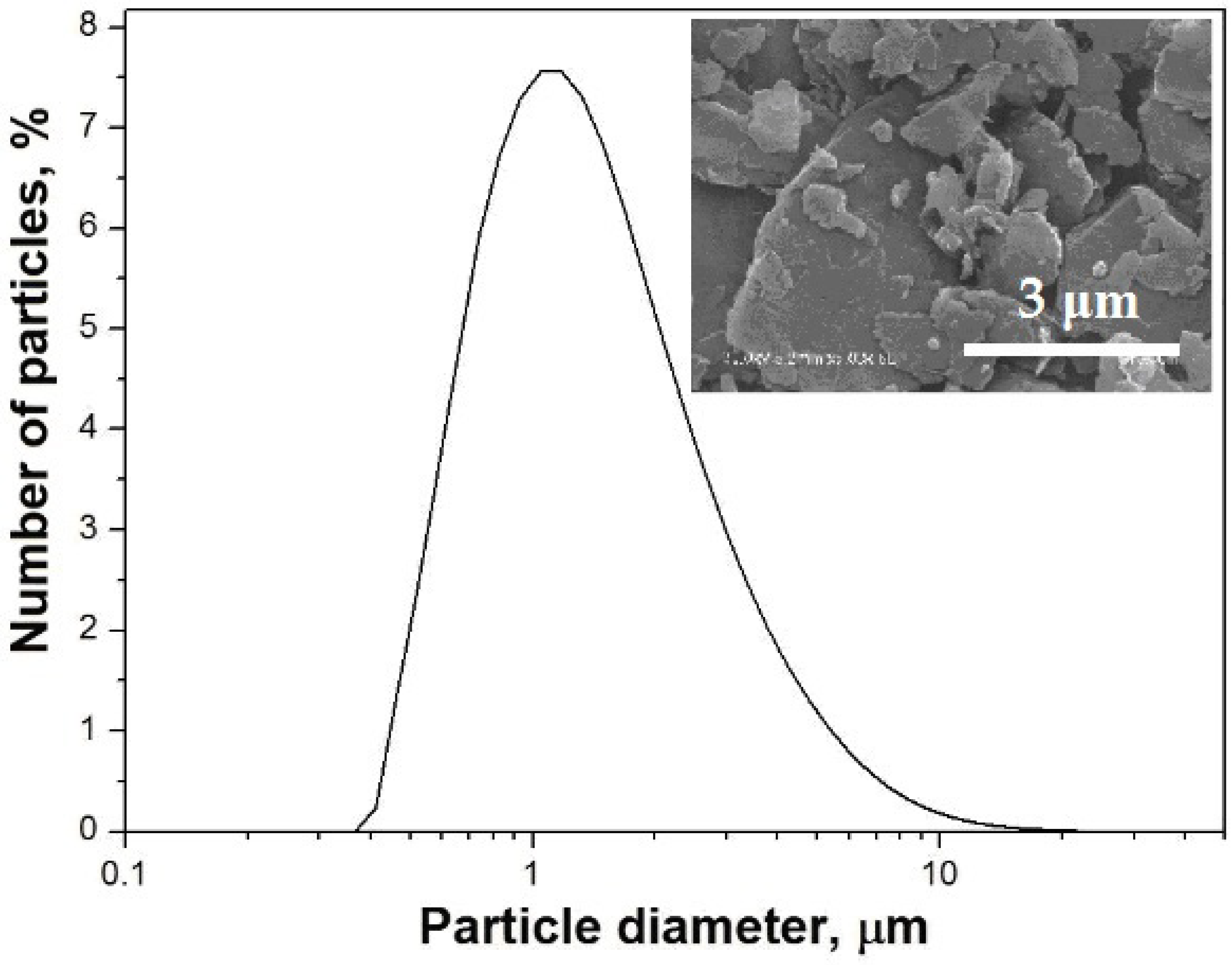
Graphite is the most often used pore former, so it was chosen as the pore former for the printed supporting anodes [
24]. Graphite was chosen as the pore former in this study because its particles are small enough to clog the printer nozzle and it is well wetted by the organic binder of the printing paste. The particle size distribution and the morphology of the pore former are shown in
Figure 10.
The as-printed NiO/YSZ anodes, both in the absence and in the presence of the pore former, were sintered at 600 °C for 1 h to first remove organics and then at 1400 °C for 2 h.
Figure 11 shows the X-ray diffraction patterns of the initial NiO/YSZ composite and a NiO/YSZ sample in the presence of 20 wt.% graphite before and after sintering. As can be seen, after sintering, there are no peaks attributed to graphite in the diffractogram, which indicates that the pore former is completely removed during heat treatment of the printed sample. The estimation of the quantitative phase composition of these samples shows that the experimental mass ratio values in the composite and in the printed sample before and after sintering coincide with those produced by calculation (
Table 3).
The images of cross sections of the as-sintered NiO/YSZ anode show (
Figure 12a,b) that in the presence of graphite, the anode structure is more porous and the ceramic particles are less sintered due to a decrease in the intergrain contacts. It can also be seen that the shape of the pores in the NiO/YSZ-based anode is similar to that of the pore former. The quantitative characterization of the anode support porosity using SEM images showed (
Table 4) that the addition of the pore former increases the porosity to values which are close to those recommended as suitable for anode-supported SOFCs, and which, according to the reported data [
25,
26], are in the range of 30–60%.


 ,
, 


