1. Introduction
Solid oxide fuel cells (SOFCs) are promising electrochemical devices for conversion of chemical energy of hydrogen and hydrocarbon fuels into electricity. The energy conversion process goes directly through electrochemical reactions, bypassing the fuel-burning stage. Compatibility of SOFCs with conventional hydrocarbon fuels along with high efficiency and nearly noiseless operation make them an attractive solution for industrial and domestic power generation.
SOFCs owe their compatibility with hydrocarbon fuels to their high operation temperatures; most of the commercial SOFC systems work at 800–100 °C. It should be noted that in the last two decades, active research on SOFCs operating at intermediate (600–800 °C) or low temperatures (500–600 °C) has been conducted [
1,
2], but these systems have not yet reached the commercialization level. High temperatures used in SOFCs not only allow use of hydrocarbon fuels, but also lead to high-quality exhaust heat that can be used for domestic or industrial heating. Unfortunately, high the operating temperature of SOFCs has its drawbacks. It increases duration of startup and stopping of SOFCs, introduces additional requirements to thermomechanical and chemical compatibility of the materials used in SOFCs, and complicates the choice of sealing materials for SOFCs [
3].
Primary functions of the sealing materials in SOFCs include dividing fuel and air streams inside the fuel cell, isolating the internal gases flow from the environment, and mechanical consolidation of separate cells into a battery. No organic-based seals can be used at 800–1000 °C, so glasses and glass-ceramics are employed instead. Choice of sealants for SOFCs is a complicated task because they should meet a number of requirements. A sealant should have a coefficient of thermal expansion (CTE) close to that of both ceramic membrane (electrolyte) and metal interconnect (usually high-chromium steel or CFY alloy), typically in the 8–12 × 10−6 1/K range. In addition, a strong adhesion should exist between a sealant and steel interconnect to ensure both impermeability for gas products and high mechanical strength of the battery. The last requirement for SOFC sealing materials is the stability of their chemical composition and physical properties during the operation of the battery.
A number of glass and glass-ceramic sealant compositions for SOFCs are reported in the literature and implemented in commercial products. Among the most frequently used chemical compositions, one may note the following:
Barium aluminosilicate glass-ceramics. Their approximate chemical composition is 45–55 mol.% SiO
2, 5–15 mol.% B
2O
3, 20–30 mol.% BaO, 5–15 mol.% Al
2O
3, minor amounts of ZrO
2, NiO, ZnO, and Cr
2O
3, and some other oxides. These glass-ceramics usually have CTE of 10.5–11 × 10
−6 1/K, nicely matching CTE of SDC and ScSZ electrolytes. They show decent adhesion to heat-resistant steel such as Crofer 22 APU [
4,
5,
6,
7,
8,
9,
10]. In these glass-ceramics, the choice of the appropriate amount of flux is crucial to obtain material with the desired softening and glass-transition temperature.
Diopside-based glass-ceramics. These glass-ceramics are also frequently used to seal SOFCs. Approximate chemical composition is 15–20 mol.% CaO, 25–35 mol.% MgO, and 45–50 mol.% Al
2O
3, and minor quantities of Al
2O
3, SiO
2, and B
2O
3 [
6,
11,
12]. These sealants also have CTE of about 10 × 10
−6 1/K and decent adhesion to conventional metal interconnect.
Modified soda–lime glass. Soda–lime glass, with the addition of alumina and increased calcia content, is sometimes considered as glass sealant for SOFCs [
4]. An example of composition used is 50–60 % mol.% SiO
2, 5–10 mol.% Al
2O
3, 24–28 mol.% CaO, and 10–14 mol.% Na
2O.
The materials mentioned above, especially barium aluminosilicate glass-ceramics, provide good sealing in SOFCs according to the literature. The procedure of SOFC sealing with these materials includes heating of the whole battery well-above its operating temperature. For example, for batteries operating at 850 °C, typical sealing temperature is 950 °C (Schott 394 glass). Dwell at the elevated temperature usually takes a few hours if conventional sealants are used so that reaction between the sealant and metal interconnect takes place and a strong interface is formed. The dwell at elevated temperatures may cause undesirable changes in the structure of electrodes due to sintering processes and may lower power output of the cell.
It is thus desirable to use glass or glass-ceramic sealant that quickly reacts with the material of a bipolar plate forming strong interface such that it remains stable under operating conditions. Indeed, other requirements for sealants still hold true for such sealants. They should be thermomechanically compatible with high-chromium steel or CFY and with the electrolyte used in the cell. Their properties should not deteriorate during the operation of the fuel cell through crystallization or through further reaction with either steel or the gas environment.
In the present work, we have investigated the glass-ceramic sealant of CaO-SiO
2-B
2O
3 system with high boron oxide content of 26 mol.% B
2O
3. This system was chosen because calcium borosilicate glasses are known to have CTE in the range 8–10 × 10
−6 1/K and glass-transition temperature about 650–700 °C [
13,
14,
15,
16]. CaO-SiO
2-B
2O
3 glasses with boron oxide content above 7–8 wt. % are rarely used as sealants for SOFCs; they primarily find applications in the sealing of microelectronic components working at near-room temperature [
17,
18,
19]. The main reason for the limited high-temperature use of these glasses is volatility of boron oxide in glasses and its ability to cause poisoning of the cathode materials when volatilized [
20,
21]. However, in the present research, we hoped to achieve a high degree of crystallization of the sealant material after heat treatment to bind the boron oxide into the crystal lattice and into reaction products with steel and thus, lower boron mobility.
The main aims of the study were the following:
Study interface between CaO-SiO2-B2O3 sealant and Crofer 22 metal interconnect after brief heat treatment or after treatment at temperatures lower than are conventionally used;
investigate thermomechanical compatibility of the CaO-SiO2-B2O3 sealant and Crofer 22 interconnects;
investigate degree of crystallinity and phase composition of the sealant after the sealing procedure both in and out of contact with steel interconnect.
2. Materials and Methods
We prepared a sealant with chemical composition 38 mol.% CaO, 26 mol.% B
2O
3, and 36 mol.% SiO
2. Choice of the composition was based on the previous publications on low-temperature applications of CaO-B
2O
3-SiO
2 seals [
13]. As initial materials for preparation of the sealant, we used >99 % pure calcium carbonate, boric acid, and silicon dioxide (Chemcraft, Russia). In order to mix the precursors homogeneously, we added bidistilled water and mixed the slurry with a laboratory mixer UED-20 (UED Group, Russia) for 5 min. The slurry was then left to dry in a laboratory oven at 100 °C for 15 h to remove water.
The dried mixture was then placed into platinum crucible and heated in air to 1500 °C at heating rate of 2.5 °C/min. Heating was conducted in a vertical load furnace LHT 02/17 LB (Nabertherm, Germany). We chose low heating rate to allow full decomposition of precursors to take place before the melting. We held the melt at 1500 °C for 1 h for the components to form homogeneous melt. Then, we quenched the melt into bidistilled water. After cooling of the water, we extracted the pieces of the resulting material and dried them at 100 °C for 2 h.
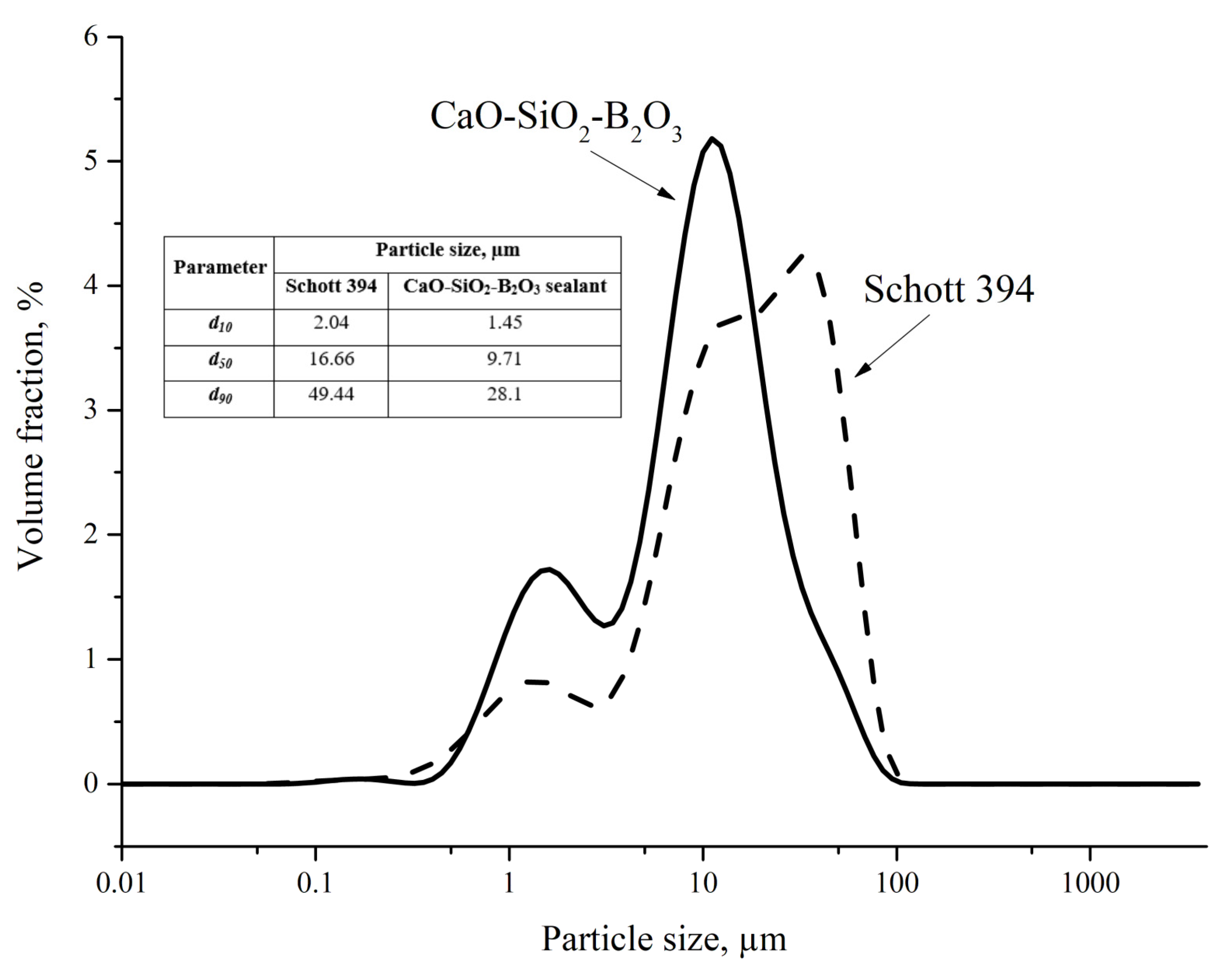
The dried pieces of the material were ground with a mechanical mortar Pulverisette 2 (Fritsch, Germany). We used zirconia pestle and mortar to minimize contamination of the material during grinding. We estimated the size of the ground powder with laser diffraction method (Analysette 22 Next, Fritsch, Germany) and compared it to size of commercially available powder glass Schott 394. For the purpose of the measurement small quantity of ground powder was dispersed in bidistilled water, ultrasonicated to break any agglomerates, and subjected to static light scattering measurement. It was performed to ensure that there was no significant particle size difference that could influence comparison of properties of the materials.
We performed X-ray diffraction (XRD) analysis of as-prepared sealants after heat treatment both in and out of contact with Crofer 22 APU. XRD analysis was performed on finely ground powder with copper X-ray tube in Bragg–Brentano reflective geometry with Smartlab (Rigaku, Japan) diffractometer. Peaks were identified with the use of PDF database. The latter was used as a reference material of a bipolar plate. XRD data were used to estimate degree of crystallinity of the material and identify crystalline phases if any were present.
We investigated high-temperature behavior of the prepared material. For this purpose, we have put about 0.3 g of the studied material on Crofer 22 APU (ThyssenKruppVDM, Berlin, Germany) plate with dimension 20 × 20 × 2 mm. The powder formed a loose cone with 10-milimeter base and about 10-milimeter height. The plate with the powder was then put to furnace and heated to a maximum temperature of 850–950 °C at 2 °C/min rate, held there for 1 h, and cooled down at the same rate. Low heating and cooling rates were chosen to minimize effects caused by CTE mismatch. Plate with the sealant was then visually assessed to estimate suitable sealing temperature of the prepared material. We ground the sealant after high-temperature treatment to prepare fine powder and performed XRD analysis of its phase compositions. We also cut rectangular samples with approximate dimensions 3 × 1 × 1 mm from the heat-treated sealant and measured its CTE in air with dilatometer L75Vertical (LINSEIS, Berlin, Germany). The samples were measured with heating and cooling rates of 3 °C/min and were held at 850 °C for 2 h. Ends of the samples were covered with thin zirconia pellets to minimize reaction of the sealant with the measurement chamber. Expansion of zirconia pellets was accounted for and subtracted from the final data.
In order to assess strength of the sealant adhesion to the Crofer 22 APU plate, we performed a mechanical test. The steel plate was fixed in a vertical position by a lower part not covered with the sealant in clamps. Then, we applied bending load to the upper part of the plate in a way such that the sealant/steel interface was under tensile stress. We registered the applied load at which delamination of the sealant occurred and calculated the corresponding flexural stress.
We also investigated microstructure of sealant/steel interface. To prepare samples for this study, we deposited a hollow square pattern of sealant on 20 × 20 × 2 mm Crofer 22 APU plate. For the deposition of the sealant, we used F4200N (Fisnar, Copenhagen, Denmark) dispenser with terpineol-glass-PVB paste. Organic components for the paste were supplied by Chemcraft, Russia. The as-deposited sealant was dried and covered on top with similar Crofer plate. This “sandwich” structure was loaded with a force of approximately 1 N and heat-treated in a furnace on the described above routine. A 150-micrometer zirconia delimiter was put in the center of the assembly to avoid leaking of the sealant under the load at elevated temperature. After cooling of the assembly, we prepared and polished cross-sections of the assembly. We prepared SEM images of the cross-sections with Supra 50 VP (Carl Zeiss, Germany) microscope. Both our material and commercial Schott 394 glass were investigated this way. We used energy-dispersive X-ray spectroscopy (EDXS) for elemental analysis of the cross-section and sealant/steel interface.
Thermal cycling tests were conducted on “sandwich” assemblies after heat treatment at 925 °C. For thermal cycling, we put the assemblies with no load applied into a furnace and heated them to 850 °C (typical temperature of SOFCs operation) with 2 °C/min heating rate, held at this temperature for 2 h, and then cooled down to room temperature with 2 °C/min cooling rate.
3. Results and Discussion
CaO-SiO2-B2O3 sealant melted at 1500 °C flowed freely from the platinum crucible into water. Its viscosity, as assessed visually, was much lower than that of barium aluminosilicate, diopside, and modified soda–lime glass sealants melted at the same temperature. The as-quenched calcium borosilicate sealant was opaque white contrary to what we observed on other types of sealants, which were transparent.
Mechanical strength of the as-quenched CaO-SiO2-B2O3 sealant was similar to that of other sealants as judged from time required to mill quenched chunks of the material into fine powder.
Particle size distribution of the CaO-SiO
2-B
2O
3 powder is presented in
Figure 1 along with the data for commercial powder Schott 394 measured under the same conditions. It is clear from the presented particle size distribution that the prepared sealant was similar to the commercial product, although with slightly narrower distribution especially for larger particles. Peaks of the distribution for our sealant lie at ~1.5 µm and at ~10–12 µm. Commercial powder has a wider distribution slightly shifted toward larger particle size with the rightmost peak at 30–40 µm. It should be noted that this peak corresponding to 30–40 µm particle can also be observed on the powder of our sealant, but there the peak is much less intensive. The difference between the distributions can be illustrated by
d10,
d50, and
d90 values of the presented data. The values are shown on the insert in
Figure 1. All the values are slightly lower for the CaO-SiO
2-B
2O
3 sealant, indicating that its particle size distribution is shifted toward lower values. The most notable difference is in
d90 value, which is predictable given the difference in the right part of the distributions.
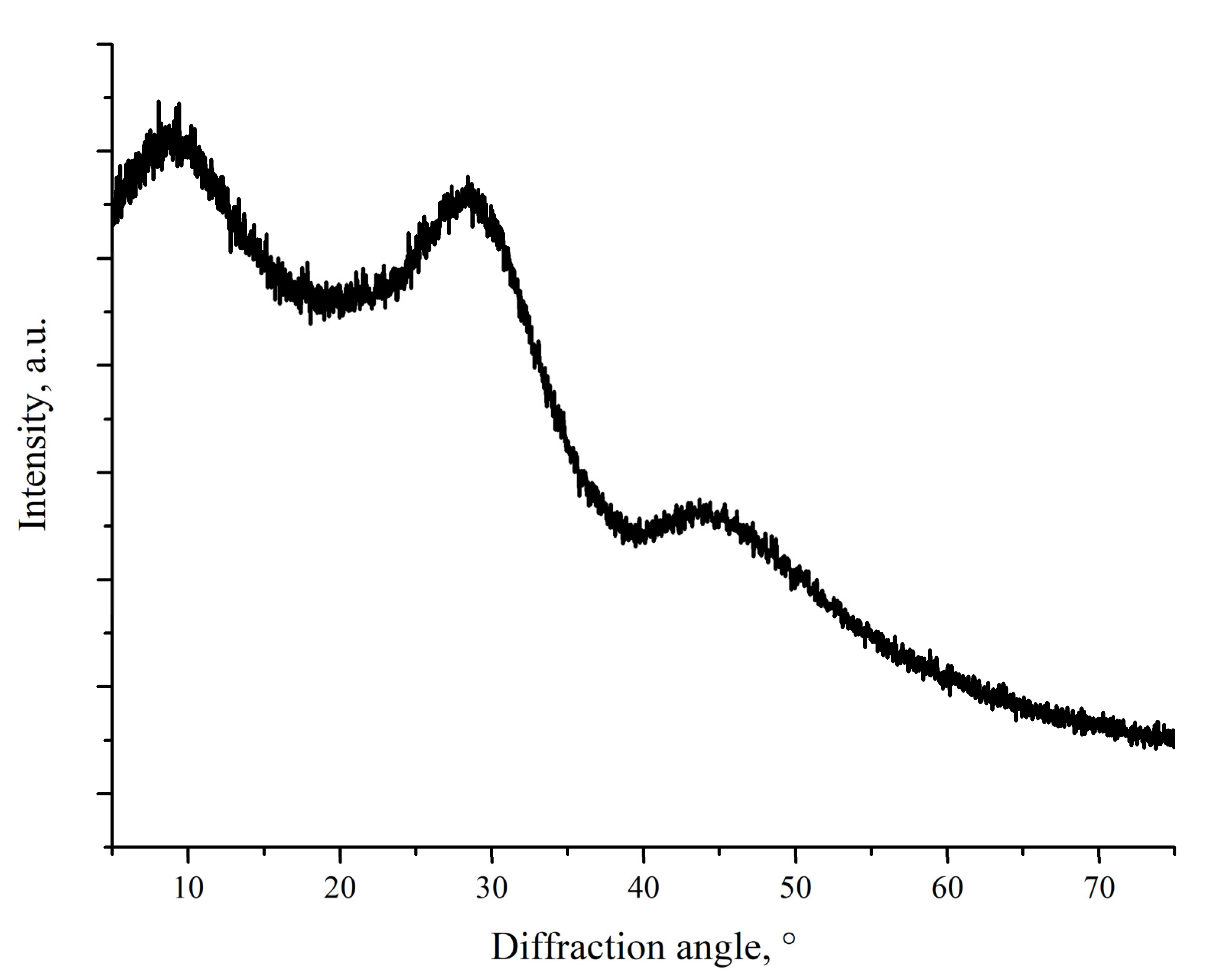
Figure 2 shows XRD pattern of the ground CaO-SiO
2-B
2O
3 sealant. No crystalline peaks can be seen; three broad amorphous halos are present instead. They correspond from left to right to interatomic distances 9.23 Å, 3.132 Å, and 2.01 Å. Among these distances, only 2.01 Å may be clearly attributed to B–O bond length [
22]. Other distance cannot be attributed to either Si–O or Ca–O bond, which have lengths of 1.60–1.65 Å and 2.45–2.54 Å [
23,
24]. The low-angle peaks may correspond not to distances between adjacent atoms, but to distance between adjacent “strands” of the glass network.
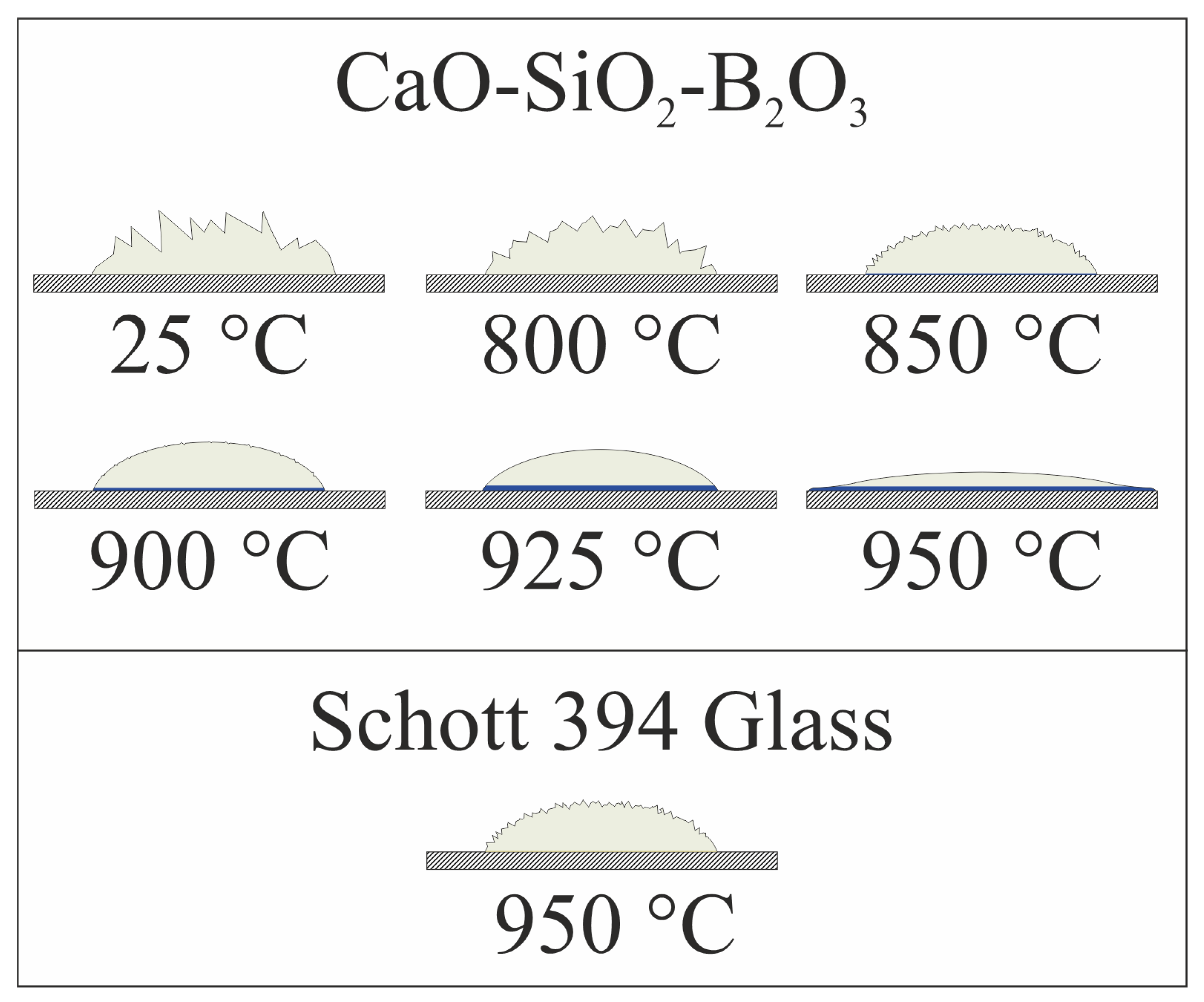
Figure 3 shows schematic depiction of the sealant-on-plate assembly after heat treatment at different temperatures for 1 h. We did not insert photographs here; because of the relatively small size of the samples, it was difficult to make a high-quality “macrophotograph”, showing the necessary details. Colors used in the figure are nearly identical to actual colors of different zones of the sealant after heat treatment. The color of Crofer 22 APU plate is shown only schematically with hatching. Relative dimensions of the sealants and the steel plate are lifelike with factual size of the plate 20 × 20 × 2 mm. Wetting angles are also shown true to life.
For CaO-SiO2-B2O3 sealant, heat treatment at 800 °C for 1 h did not cause any notable change in the geometry of the powder pile. Sharp edges of the particles remained and the particles themselves were only loosely bound to each other. We observed no reaction zone on sealant/steel interface. Increase in the temperature to 850 °C led to some softening of the angles of the powder pile and to the formation of a thin (~ 100 um), but notable layer of dark blue color at the interface with steel. Even further increase in temperature led to progressive softening of the relief of the pile and thickening of the blue layer to ~300 µm at 925 °C. At this temperature, surface of the sealant became smooth, forming a drop, slightly wetting the steel plate. It indicates that the glass softening point lies between 850 °C and 925 °C. For samples heated to 950 °C, we observed spreading of the sealant over the surface of the plate, demonstrating excellent wetting and low viscosity of the sealant. The latter is undesirable for sealing of SOFCs because low-viscosity sealant may flow from the designed areas and block air or fuel channels. In the following discussions, part of the sealant that was not in direct contact with the steel plate and did not change color significantly is named “White area”. The part that was in contact with the plate and changed its color to saturated blue is named “Blue area”. The key difference between these regions is that the former represents change in the sealant itself after the heat treatment, while the latter represents products of interaction of the sealant and Crofer plate. Experiments with Schott 394 glass were conducted only for 950 °C because it is a recommended sealing temperature for this sealant. The degree of the sealant softening at this temperature was similar to that of CaO-SiO2-B2O3 sealant at 850 °C. Significant visual difference lies in the color of the contact layer on the interface with steel. The color is saturated yellow as opposed to the dark blue of CaO-SiO2-B2O3.
Mechanical test of adhesion strength was performed on samples with CaO-SiO
2-B
2O
3 sealant heat-treated at 925 °C and on Schott 394 sealant heat-treated at 950 °C. We registered the bending load was applied when the delamination of the sealant from the steel plate took place. In the case of Schott 394, sealant delamination occurred at a load of 11 N, which corresponded to flexural stress of 0.12 MPa. In the case of CaO-SiO
2-B
2O
3, delamination of the sealant took place at a load of 28 N, corresponding to flexural stress of 0.31 MPa. In the present experiment setup, flexural stress represents tensile stress at steel-sealant interface in the interface plane; therefore, it can be said that the strength of the CaO-SiO
2-B
2O
3 adhesion to steel surface is approximately 2.5 times higher than that of Schott 394 sealant. It should be noted that during exfoliation of the studied sealant, it came of the steel surface with significant starting velocity unlike what was observed on the Schott 394 sealant. Such behavior may follow from both external mechanical stresses introduced during the test and from thermomechanical stresses generated at sealant–steel interface due to possible CTE mismatch. Since it is likely that the appearance of the blue zone on the sealant/steel interface was a result of the reaction between the CaO-SiO
2-B
2O
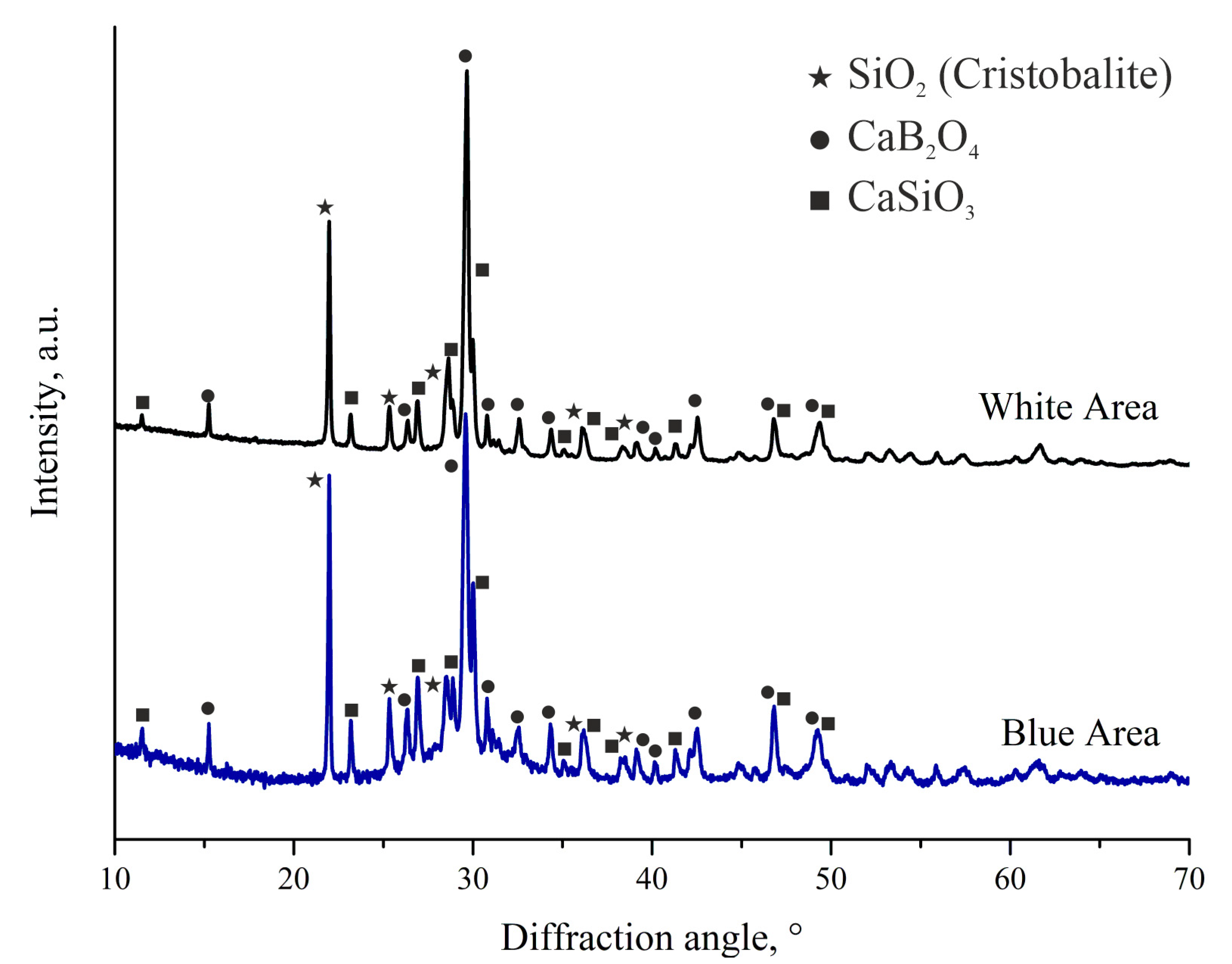
3 sealant and steel, we performed XRD study of both white and blue areas of the sealant after heat treatment at 925 °C.
Figure 4 shows XRD patterns for both of these areas.
Sealant that was not in contact in Crofer plate is fully crystallized (upper curve in
Figure 4). The most prominent crystalline phases attributed to the observed peaks are CaB
2O
4 (PDF 00-032-0155), SiO
2 (Cristobalite modification, PDF 00-039-1425), and CaSiO
3 (PDF 00-043-1460). The amount of amorphous phase in the white area is negligible. The ratio between CaSiO
3 and CaB
2O
4 allowed us to estimate boron content in the heat-treated sealant; it turned out to be close to the nominal value. XRD pattern of the blue area shows the same crystalline phases with similar molar fractions of the phases with a slightly higher CaSiO
3/CaB
2O
4 ratio, which may serve as an indication that part of boron oxide took part in reaction with the steel plate. The products of the reaction are likely to be amorphous, as evidenced by the appearance of an amorphous halo on the XRD pattern. We detected no crystalline phases containing iron or chromium (main components of Crofer 22 APU steel) in the blue area. However, the coloration itself hints at the presence of Cr
3+ ions in the interface area. It may be assumed, thus, that the amorphous phase is formed through reaction of at least boron oxide and components of the steel plate. Of course, other components of the sealant could take part in the formation of the amorphous layers. XRD patterns show that the sealant after heat treatment is glass-ceramic in the area near the bipolar plate. Taking into account that thickness of the seal is usually well-below 500 µm, we may safely assume that the entire seal will be composed of the “blue” zone, meaning that the seal will be in the glass-ceramic state after the sealing procedure.
It was difficult to calculate molar fractions of the crystalline phases in powder prepared from the blue area because of the significant contribution of the amorphous phase. Roughly, ratios of the crystalline phases may be estimated to be 55 mol.% CaSiO3, 30 mol.% CaB2O4, and 15 mol.% SiO2. We managed to calculate the amount of amorphous phase only approximately to be 60–70% of total crystalline phases content. CTEs of the present phases are, according to the literature:
CaSiO
3 has a CTE of 11.2 × 10
−6 1/K in a wide range of temperatures, as calculated from high-temperature crystallographic data on CaSiO
3 reported in the literature [
25].
We found no results on CTEs of CaB
2O
4 in the literature. The closest match we found in the literature is a paper by Kluev et al. [
26], where the authors reported CTE of glass consisting of 40 mol.% CaO and 60 mol.% B
2O
3 to be 7.29 × 10
−6 1/K in 20–300 °C range. Other results mentioned in the paper imply that material with 50 mol.% CaO and 50 mol.% B
2O
3 may have slightly higher CTE.
SiO
2 in β-cristobalite has a CTE changing significantly with temperature, having CTE of 10.9 × 10
−6 1/K at 100–500 °C rapidly falling to 1.7 × 10
−6 1/K in 500–1000 °C [
27].
Among the present crystalline phases, cristobalite, predictably, has the lowest average CTE in the 100–850 °C range. It means that cristobality may serve as a main source of thermomechanical stresses on the sealant-interconnect interface, which may be somewhat mitigated by the glassy phase presenting dampening CTE mismatch. Crystallization of SiO2 is an undesirable process, lowering overall CTE of the sealant and causing internal thermomechanical stresses. This process should be suppressed by the introduction of additional components to the sealant. We plan to use them in the process of further development of the reported sealant.
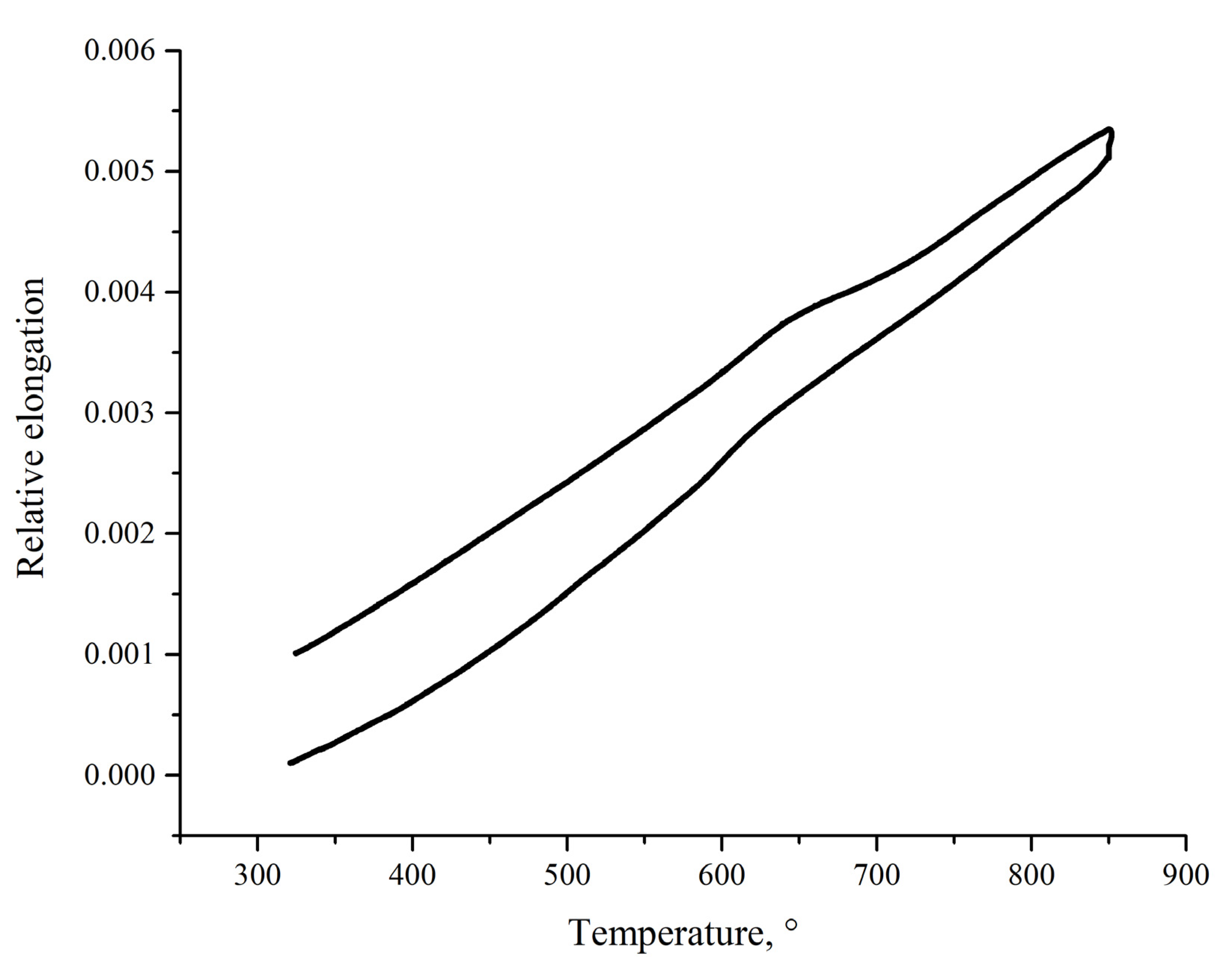
To assess thermomechanical compatibility of the sealant and Crofer 22 APU, we cut a rectangular sample of the sealant after heat treatment at 925 °C. We managed to prepare suitable samples from the white area of the treated sealant because the blue area was too thin (<300 µm). Of course, in the case of SOFCs sealing, the sealing space will be filled with the material with phase composition of the blue area because of typically low thickness of the seal (usually well-below 500 µm). Nonetheless, dilatometric data obtained on the white (
Figure 5) area may give a useful insight into properties of the blue area because of the closeness of their phase composition.
It should be noted that the data presented in
Figure 5, obtained on the sealant after heat treatment, does not illustrate properties of the original glass. Instead, it shows properties of the sealant after the sealing procedure, which, we believe, are more important when studying thermomechanical compatibility of the sealant and steel. Average CTE in range 400–850 °C is 8.4 × 10
−6 1/K. This value is lower than CTE of Crofer 22 APU (11–12 × 10
−6 at 800–900 °C) and than that of zirconia electrolyte (10.5–11 × 10
−6 1/K). CTE of the CaO-SiO
2-B
2O
3 sealant is close to that of Schott 394 glass–8.6 × 10
−6 1/K. It allows us to assume that a sealant with CTE equal to 8.4 × 10
−6 1/K is thermomechanically compatible with Crofer 22 APU and zirconia-based electrolytes. Since the data were obtained on the sealant crystallized after heat treatment, it is impossible to determine the glass-transition temperature from the presented dilatometry data.
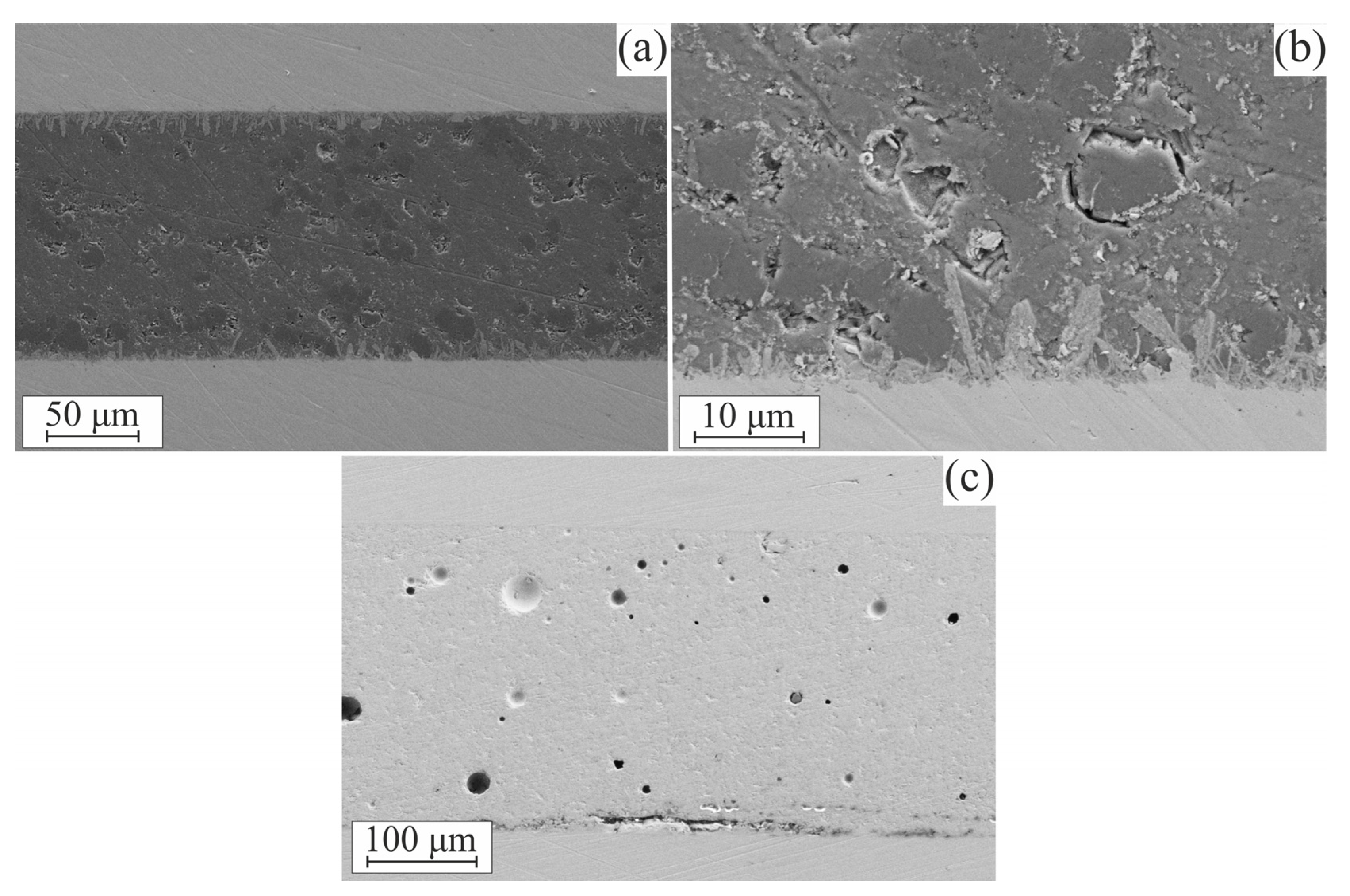
SEM images of the steel–sealant–steel assembly cross-sections are presented in
Figure 6.
Figure 6a,b features an assembly with the CaO-SiO
2-B
2O
3 sealant. It can be seen that a strongly pronounced interaction area is formed; it consists of elongated formations with predominant orientation normally to the interface surface. The interaction area appears consistently along the entire sealant–steel contact surface. The sealant layer all along the studied surface showed a solid structure without cracks or extensive pore networks, which could lead to the loss of impermeability of the material. We have also held some samples at the operation temperature of 850 °C for 100 h to examine if the reaction zone propagates further into the sealant. We found no evidence of such behavior; SEM images of as-heat-treated and aged samples were hard to distinguish from each other.
In the assembly with Schott 394, the interaction area was not pronounced, as can be seen in
Figure 6c. SEM images of the assembly with Schott 394 sealant show regions where delamination of the sealant from steel surface is observed (central part of the lower interface in
Figure 6c). The delamination might have taken place due to possible factors: (a) poor adhesion combined with thermal stresses at the interface or (b) contamination of the steel plate surface prior to sealant deposition. The latter is unlikely because of the careful preparation of the samples and consistency of the appearance of the areas with delamination, but it cannot be entirely ruled out.
The reported CTE of the sealant is lower than that of steel interconnect or zirconia electrolyte. The CTE mismatch causes thermomechanical stress, which was not high enough to lead to immediate delamination of the sealant, according to conducted mechanical tests. It, however, may lead to the degradation of the interface upon thermal cycling. SOFCs rarely undergo a high number of thermal cycles to room temperature, since they usually operate at a nearly constant temperature for prolonged periods. Nevertheless, a sealant-interconnect interface should withstand a small number of cycles inevitably occurring at startups or stops of the SOFC battery. We have thermally cycled the steel-sealant–steel assembly 20 times and after that obtained an SEM image of the polished cross-section. We have observed no delamination or cracking of the sealant after 20 cycles. It may be supposed that CTE of the reaction zone (blue zone) is different from that of the bulk sealant, perhaps having intermediate value between bulk sealant and steel interconnect, thus avoiding generation of large amounts of thermomechanical stress on the interface. However, it is only an assumption, since we were not able to prepare a sample for dilatometry from the reaction zone because of its small size. Another possible assumption, which is indirectly supported by the SEM images of the interface, is that adhesion on the interface is strong enough to withstand the thermomechanical stress.
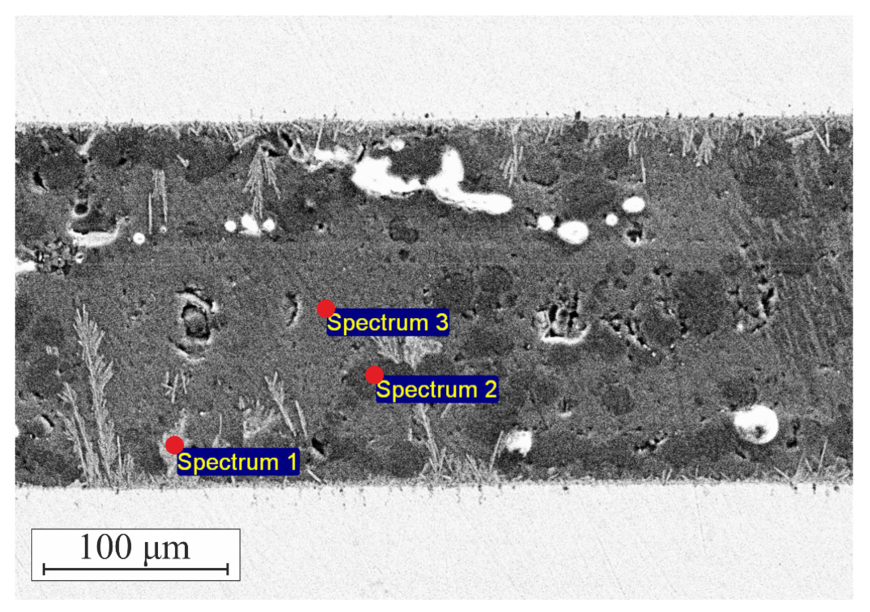
For EDXS analysis of the sealant–steel assembly, we intentionally performed heat treatment of the assembly at 925 °C for 6 h instead of 1 h. The purpose of such treatment was to grow the sealant–steel interaction zone to obtain more reliable data on the elemental composition. Prolonged exposure to high temperatures caused intensive growth of the interaction zone with dendrite formations growing deep into the sealant layer.
Figure 7 shows points where elemental composition was measured; these points are: (a) large dendrite formations originating at sealant–steel interface, (b) dark contrast regions in the sealant, and (c) gray-contrast areas in the bulk of the sealant.
Table 1 summarizes our findings on the compositions in these points. It should be noted that EDXS does not allow detection of boron so boron is not listed in the table, but is indeed present as evidenced by XRD data (
Figure 4).
The gray-contrast area (point 3 in
Figure 7) contains mostly Ca, Si, and O with minor quantities of Cr and Fe. Presented in
Table 1, elemental composition in the point cannot be attributed to either CaSiO
3, SiO
2, or their mixture because of Ca/Si and Ca/O ratios. It is evident that the disbalance in the amount of the elements is due to the presence of the CaB
2O
4 phase. Darker contrast regions (point 2) show almost purely SiO
2 with some minor amounts of CaSiO
3. Dendrite formations at the interface contain large amounts of Cr and Si with a little Ca. It shows that at the sealant–steel interface, the sealant predominantly reacts with Cr. The ratios Cr/Si and Cr/Ca allow us to safely assume that the reaction product contains significant amounts of B. The latter was expectable because of the high reactivity of boron. Furthermore, it agrees with the observations made from XRD patterns of the reaction zone.
The main observed shortcoming of the studied sealant is its relatively low CTE of 8.4 × 10
−6 1/K, which is lower than CTEs of most materials used in SOFC. For example, metal interconnects and zirconia electrolytes usually have a CTE of about 11 × 10
−6 1/K. CTE of the studied sealant is also low relatively to CTEs usually offered by reported sealants. For example, barium aluminosilicate sealants often have CTEs of 8.5–14 × 10
−6 [
4,
9]. Calcium aluminosilicates may have CTEs in a wide range including 7–12 × 10
−6 1/K, depending on the composition with higher values of CTE observed at low-silica and high-calcia contents [
28]. Despite this difference in CTEs, it is close to that of commercially supplied sealants for SOFC, e.g., Schott 394 glass designed for high-temperature SOFCs has a CTE of 8.6 × 10
−6. Low CTE of the studied sealant is likely caused by the presence of cristobalite and calcium metaborate phases with low CTE. It may be possible to improve thermomechanical properties of the sealant by substituting part of CaO for SrO or by introducing some additional components such as La
2O
3 [
4].
It should be noted that we only managed to measure CTE of the heat-treated sealant that was not in contact with the steel interconnect. According to our XRD data, the part that was in contact with the interconnect contained a significant amount of glassy phase with some dissolved Cr3+ ions, as evidenced by EDXS data and by coloration of the reaction zone. This glassy phase likely has CTE intermediate between that of heat-treated sealant and steel interconnect, as indirectly evidenced by SEM images showing no cracks at the cross-section of steel–sealant assembly.
The glass-transition temperature of the prepared sealant was not measured, but it can be estimated from the literature data to be around 650–700 °C [
17,
18,
19]. A high content of glassy phase after sealing along with a relatively low glass-transition temperature and excellent adhesion to the metal interconnect surface suggest that the prepared sealant may be suitable for the sealing of SOFCs with an operation temperature of 800–850 °C.


