You are currently viewing a new version of our website. To view the old version click .
Applied System Innovation
  • Article
  • Open Access

5 November 2025

Deployable and Habitable Architectural Robot Customized to Individual Behavioral Habits

,
,
,
and
1
School of Architecture, Tianjin University, Tianjin 300072, China
2
School of Architecture, Carnegie Mellon University, Pittsburgh, PA 15213, USA
*
Author to whom correspondence should be addressed.
This article belongs to the Special Issue Autonomous Robotics and Hybrid Intelligent Systems

Abstract

Architectural robotics enables physical spaces and their components to act, think, and grow with their inhabitants. However, this is still a relatively new field that requires further improvements in portability, customizability, and flexibility. This study integrates spatial embedding knowledge, small-space design principles based on human scales and behaviors, and robotic kinematics to propose a prototype robot capable of efficient batch storage, habitability, and autonomous mobility. Based on the spatial distribution of its user’s dynamic skeletal points, determined using a human–computer interaction design system, this prototype robot can automatically adjust parameters to generate a customized solution aligned with the user’s behavioral habits. This study highlights how considering the inhabitant’s personality can create new possibilities for architectural robots and offers insights for future works that expand architecture into intelligent machines.

1. Introduction

Architectural robotics that can sense, plan, and act for adaptive spatial configurations is an evolving field []. Architectural robotics extends beyond static rooms accessorized with movable windows, façades, roofs, or other partitions; it involves overall structures that are operable and capable of intelligently interacting with their inhabitants. While this is widely regarded as the next frontier of human–machine interaction, research in this field is still in its early stages and few constructed examples exist. At present, architectural robotics have several drawbacks that need to be improved, as follows: (1) Most architectural robots are poorly portable. They are not only individually bulky but also lack combination considerations, making them inconvenient to transport and store in batches. (2) Their uniform design fails to meet the personal preferences of different occupants. The spatial parameters of an architectural robot are mostly determined in advance by the manufacturer, typically allowing no customization options for users. (3) Although some architectural robots can be used as temporary shelters or traveling tents, their mobility is poor. Most architectural robots cannot follow their occupants autonomously, requiring the user to stow and then carry them to the new spot.
Deployable structures and customizable design systems are potential solutions to these issues. A deployable structure can change shape from a compact to an expanded shape due to its extension and rotation properties [,]. Scissor-like structures are the most common type of deployable structures and have been widely used in foldable and mobile devices in architecture and engineering. Customizable design systems enable users to parametrically design their own devices or commodities depending on their physical characteristics, use cases, and tastes. This can generate various results to suit the different needs of users and has been applied in automobiles, medical devices, and other fields [,]. Our motivation is to introduce scissor structures and customizable systems to architectural robotics to improve portability, customizability, and mobility. The workflow follows a “sensing–computing–fabricating” data chain. After monitoring the living habits of the occupants, the system will automatically generate the geometric results of the scissor-like structure and output the fabrication data of the components accordingly. We also equipped the robot with a Bluetooth module to control its movements via a handle. The proposed architectural robot can be used as a temporary shelter after a disaster or as a travel tent.
The main contributions of this study are summarized as follows:
(1)
A foldable robotic prototype based on scissor mechanisms is designed. When folded, multiple robots are arranged in a tessellated layout for efficient bulk storage and transport. When deployed as living space, the device rapidly unfolds to form a compact area supporting basic user activities.
(2)
A user-oriented design system is built by linking spatial modulation with individual living habits. The customizable system allows users to design an individualized architectural robot depending on their body features, behavioral habits, and personal tastes. The system is user-friendly, with an easy-to-use interface that facilitates real-time interaction.
(3)
A moving method that allows the architectural robot to follow its owner is developed. We designed the gait pattern of the architectural robot by referring to the locomotion of quadruped animals. With a self-developed script, the user is able to control when the robot starts and stops moving.
(4)
An example of such an architectural robot was constructed to demonstrate the feasibility of the method. The “Design–Optimization–Fabrication” workflow of the experiment is illustrated, and the specific fabrication data is presented.

3. Methodology

3.1. Portability: Develop a Deployable and Inhabitable Robot Prototype

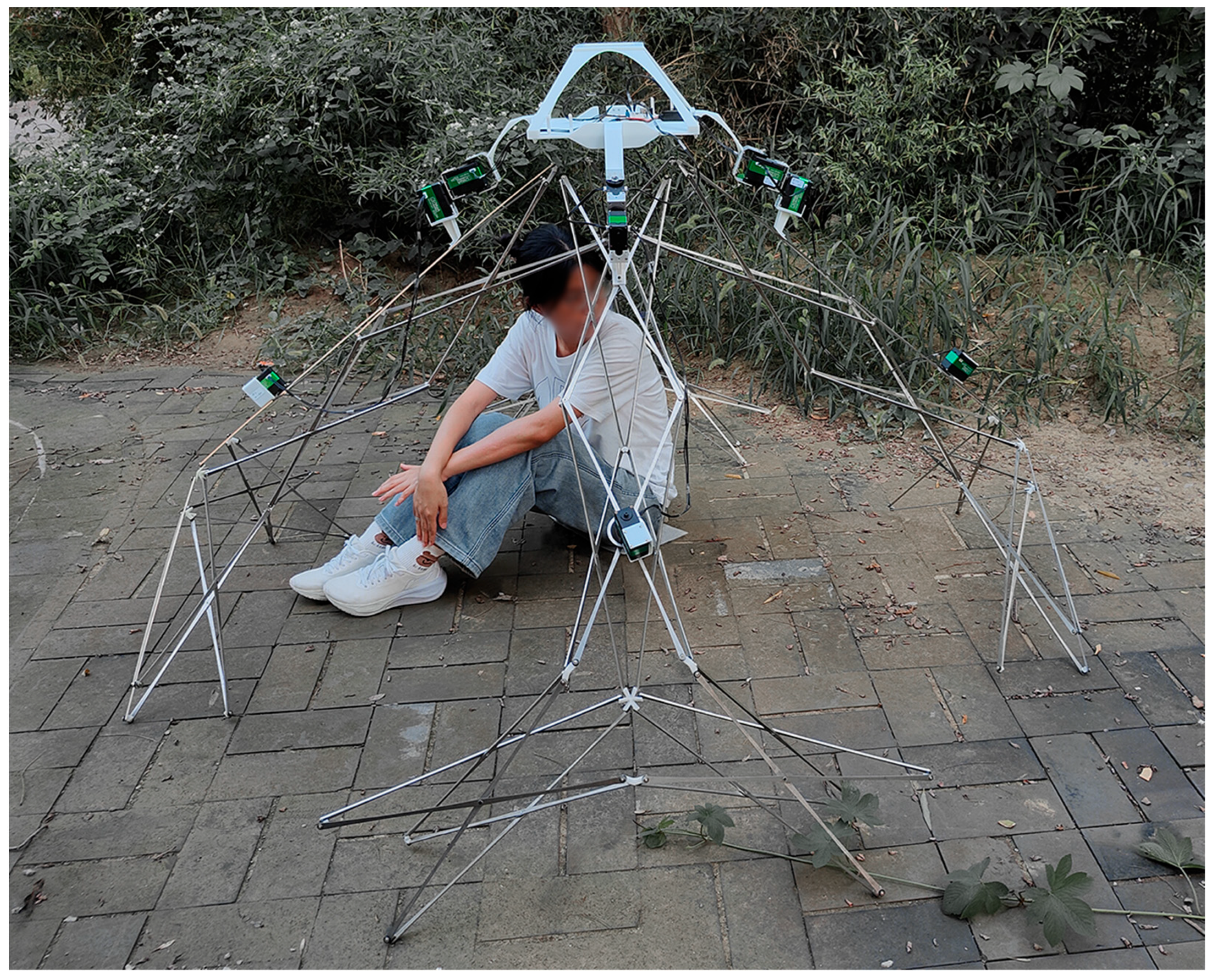
We designed a deployable and inhabitable skeleton prototype of the architectural robot based on scissor structure and spatial tessellation. The prototype comprises a “core” and several “legs.” The core controls the states and shapes of the architectural robot by managing the extension and rotation of its legs. Each leg is made of a deformed scissor-like structure and is connected to the core. When the legs are folded up, the robot takes up very little space (Figure 1a). However, when the robot arrives at the habitation site, the occupant can press the switch to extend the legs rapidly (Figure 1b). This creates a dome-like structure that can accommodate one person (Figure 1c).
Figure 1. Skeleton prototype of the architectural robot in folded state (a), half-folded state (b), and unfolded state (c).
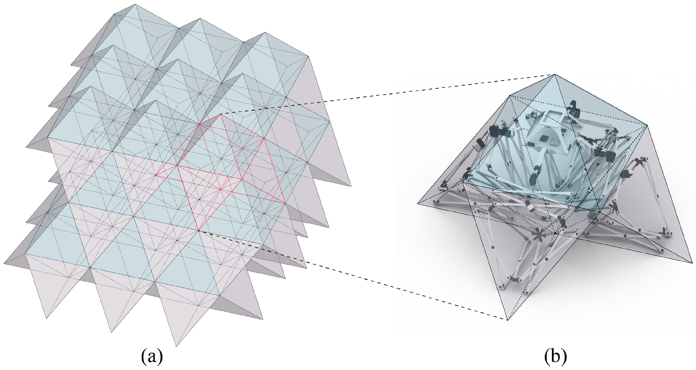
In designing the prototype’s shape, we considered space filling to save space required for bulk storage and transportation. In the field of geometry, space filling is the operation of filling space with polyhedrons without any gaps. Space filling can be achieved with a single type of polyhedron, such as cubes and truncated octahedrons. It can also be realized by combining several types of polyhedrons. In this project, we chose a combination of regular octahedrons and regular tetrahedrons for space filling. As shown in Figure 2, the octahedrons present the cores of the architectural robot, while the tetrahedrons present its legs. Each folded robot unit consists of one regular octahedron and four regular tetrahedra, forming an interlocking module.
Figure 2. The folded state of the architectural robot cluster enables a dense spatial arrangement through an interlocking pattern. As shown in the diagram, a space of just 16.2 cubic meters can accommodate 27 (3 × 3 × 3) architectural robots, the red outline represents a tessellation unit (a). Each tessellation unit is a folded architectural robot. A tessellation unit consists of one regular octahedron and four regular tetrahedra, with the two regular polyhedra sharing edges (b).
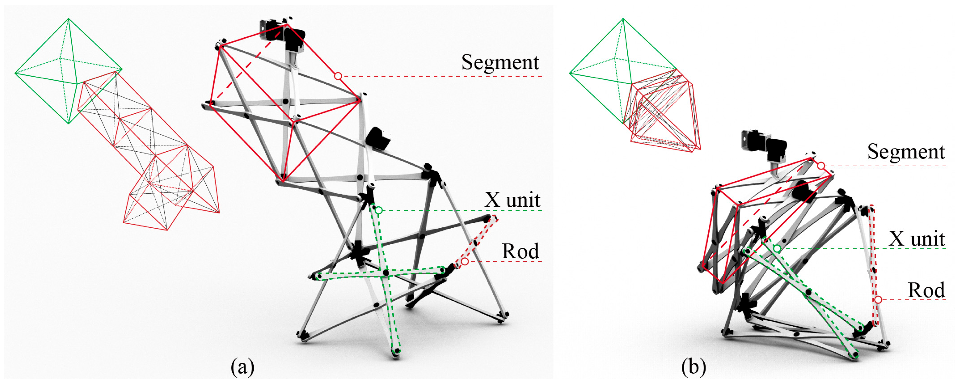
The deployable legs of the architectural robot were designed using a three-dimensional scissor-like structure, with each leg comprising 4 segments containing 12 “X”-shaped units, as depicted in Figure 3. The faces of the 3 X-units in each segment create a triangular prism, providing more robust support compared to a flat scissor design. The first segment’s center axis of the tri-prism is perpendicular to one of the faces of the lower part of the octahedral core. The top face of the tri-prism’s second segment aligns with the first segment’s bottom face. The top faces of the third and fourth segments share the same shape as the bottom face of the second segment and have a common vertex. Multidirectional nodes connect the X-units within the tri-prisms. When the legs are folded, all X-units rotate, and each segment of the tri-prism is substantially flattened.
Figure 3. Leg in unfolded state (a) and in folded state (b) using a three-dimensional scissor-like structure.
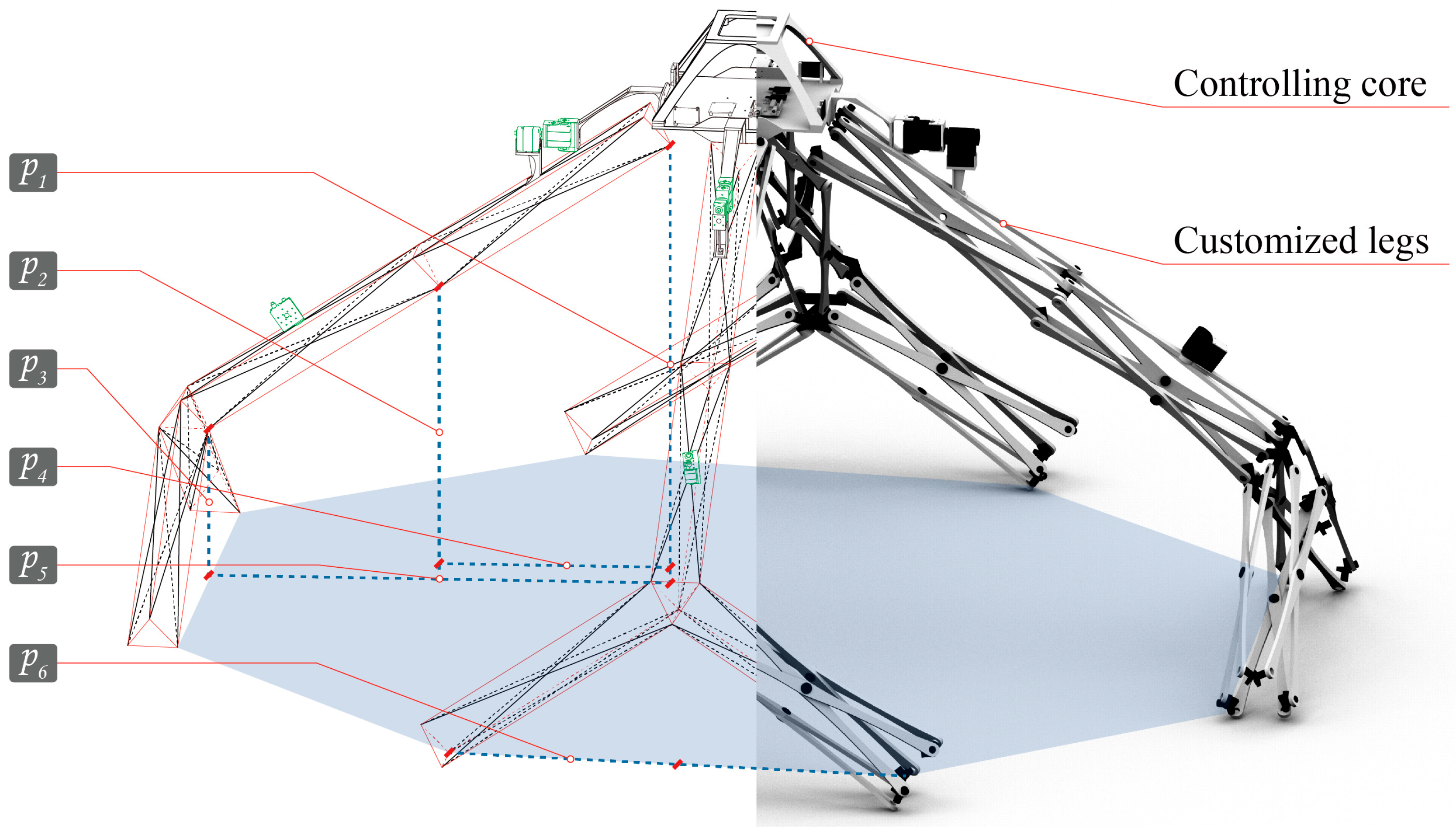
The space that an architectural robot encloses can be customized according to its occupant’s body features and behavior habits. We utilized the parametric modeling method to tailor the space by six parameters, as illustrated in Figure 4. Parameters p 1 , p 2 , and p 3 represent the heights of the lowest point on the top surface of each triangular prism. Parameter p 4 indicates the length of the horizontal projection of the first segment of the leg. Parameter p 5 is the length of the horizontal projection of the first two segments combined, while Parameter p 6 measures the horizontal projected length of the third segment. In its fully extended state, the initial values for each parameter are set to 850 mm, 550 mm, 275 mm, 400 mm, 800 mm, and 400 mm. This configuration generates a dome-like space covering approximately 3 m2, suitable for accommodating a single user (Figure 5). The method for adjusting the values of p 1 to p 6 based on the user’s behavioral habits will be discussed in Section 3.2.
Figure 4. The form of the architectural robot is adjustable using 6 parameters (The black lines in the diagram represent abstracted leg rods of the architectural robot, solid black lines denote unobstructed rods, while dashed black lines indicate obstructed rods; Red lines form a three-dimensional prism composed of scissor structures, which are not solid; Blue dashed lines indicate which segment corresponds to each parameter, and red short lines mark the endpoints of each parameter segment).
Figure 5. The prototype’s initial values were set based on the average body scale of a typical person, allowing the occupant to perform basic activities within it.
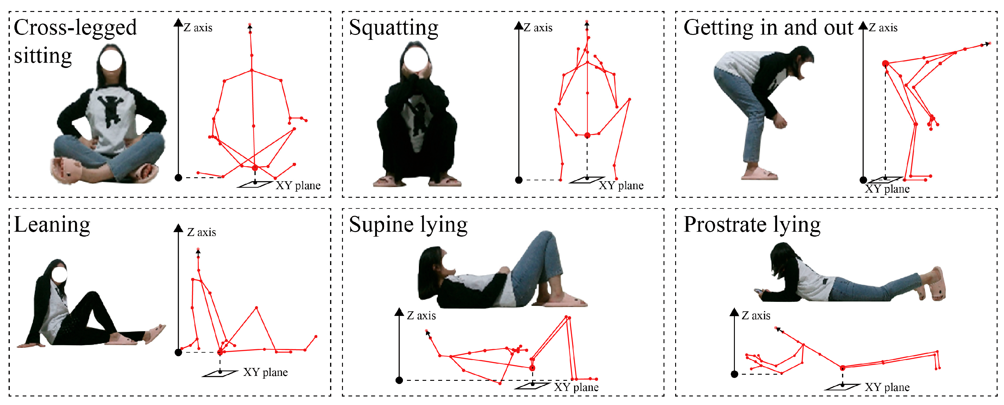
We have detailed the range of behaviors and postures this architectural robot can accommodate. As shown in Figure 6, these postures have been categorized into six types: supine lying, prostrate lying, squatting, cross-legged sitting, leaning, and entering and exiting. Each posture is suited to a specific spatial region within the robot. For instance, the longest catercorner region is ideal for supine or prostrate sleeping, while the edge areas are perfect for leisurely leaning against the robot’s legs. Given the limited space inside the robot, some activities will inevitably occupy overlapping regions.
Figure 6. In the prototype, the occupant is able to perform six activities, including supine lying, prostrate lying, squatting, cross-legged sitting, leaning, and entering and exiting.

3.2. Customizability: Developing a User-Oriented Customizable Design System

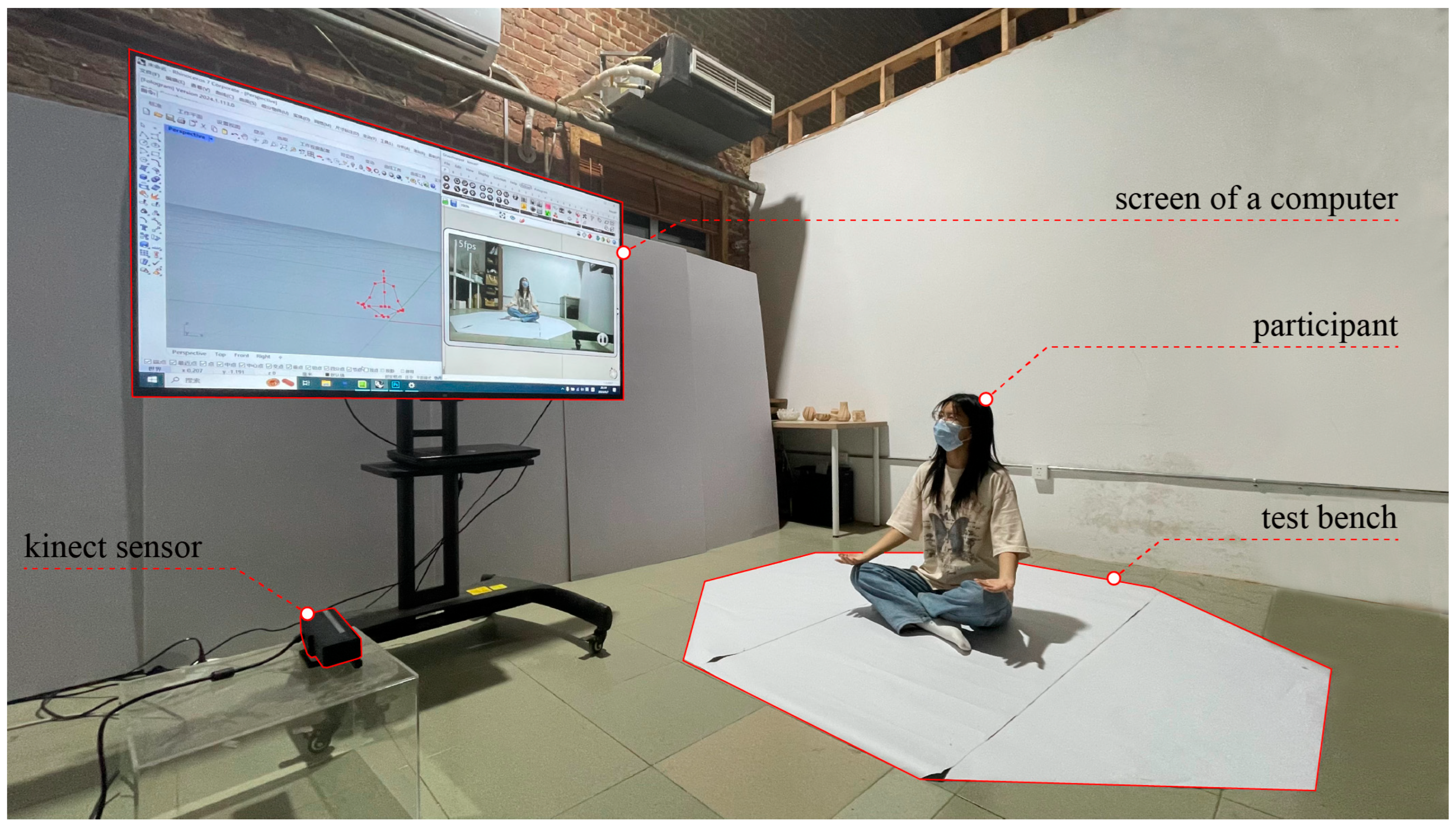
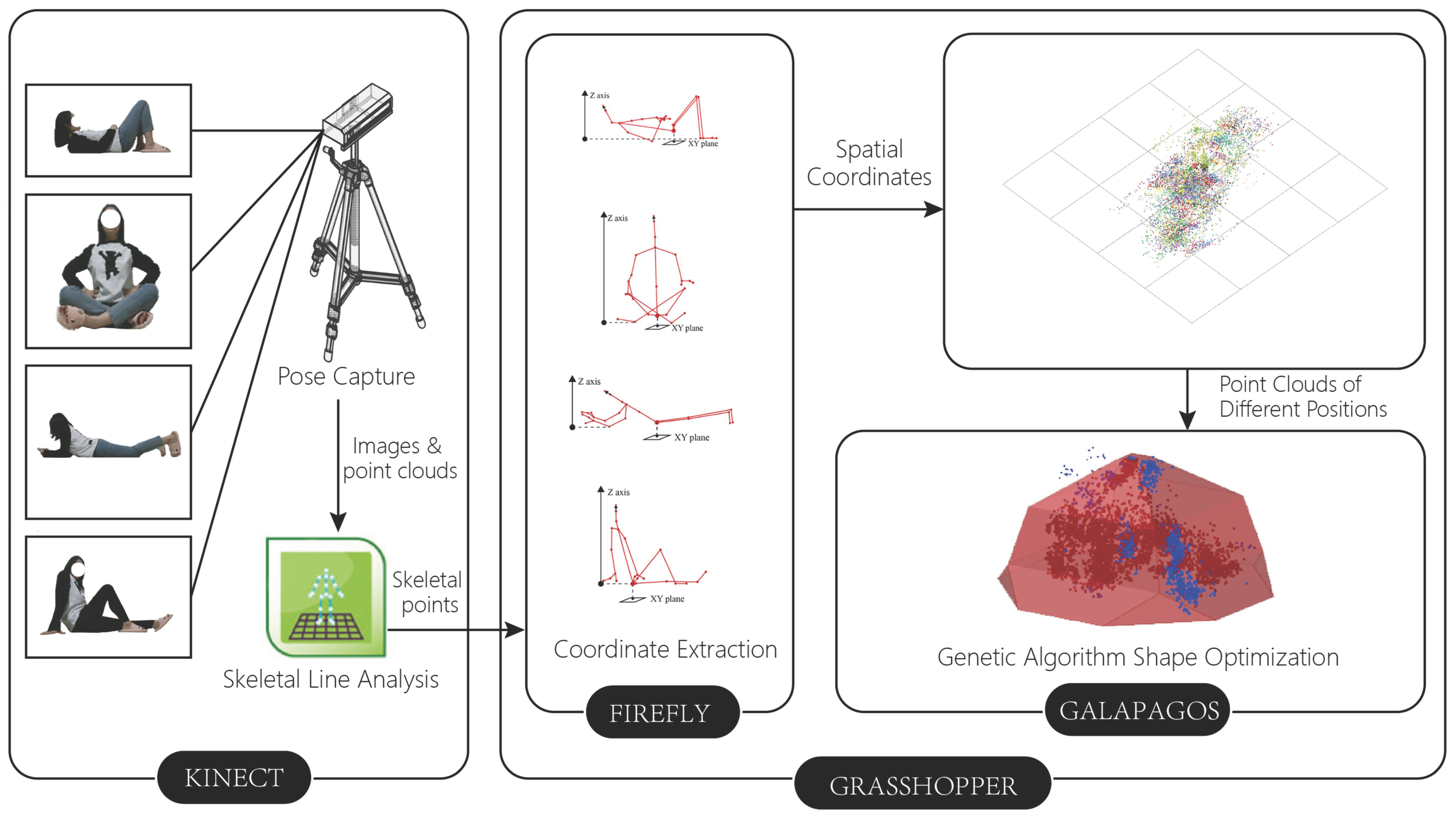
In this section, we present an adaptable design system that allows the architectural robot to customize its spatial morphology based on the user’s body features and living habits. Our system was developed using Rhino-Grasshopper, the same platform utilized for prototype modeling []. As illustrated in Figure 7, the hardware setup includes a Kinect sensor, a computer, and a testing bench. The workflow of the entire design system is illustrated in Figure 8. The process begins with data acquisition. Participants complete the six activities described in Section 3.1 within the testing area. During this phase, a Kinect camera captures images and point clouds of the participants’ various postures. Kinect Studio, the software bundled with Kinect, performs real-time analysis of the acquired data. It employs a voting algorithm to compute human skeletal points and lines in real time. Next, the Firefly plugin within the Grasshopper platform integrates the analysis results from Kinect Studio, recording joint coordinates for different postures. This transforms abstract human movements into a spatial point cloud suitable for quantitative computation. The final step involves optimizing the design prototype introduced in Section 3.1 using genetic algorithms. We utilized the Galapagos plugin for Grasshopper to perform iterative morphological optimization. By programming relevant algorithms, Galapagos can refine the original model within specified parameter ranges, thereby determining the spatial volume capable of accommodating the maximum number of user-defined skeletal points under volumetric constraints. This workflow achieves seamless integration from human motion capture to parametric architectural form optimization, generating spatial configurations responsive to user behavior while outputting six morphological parameters for the skeletal prototype.
Figure 7. The user-oriented customizable design system for shaping the architectural robot.
Figure 8. Adaptable design system workflow.
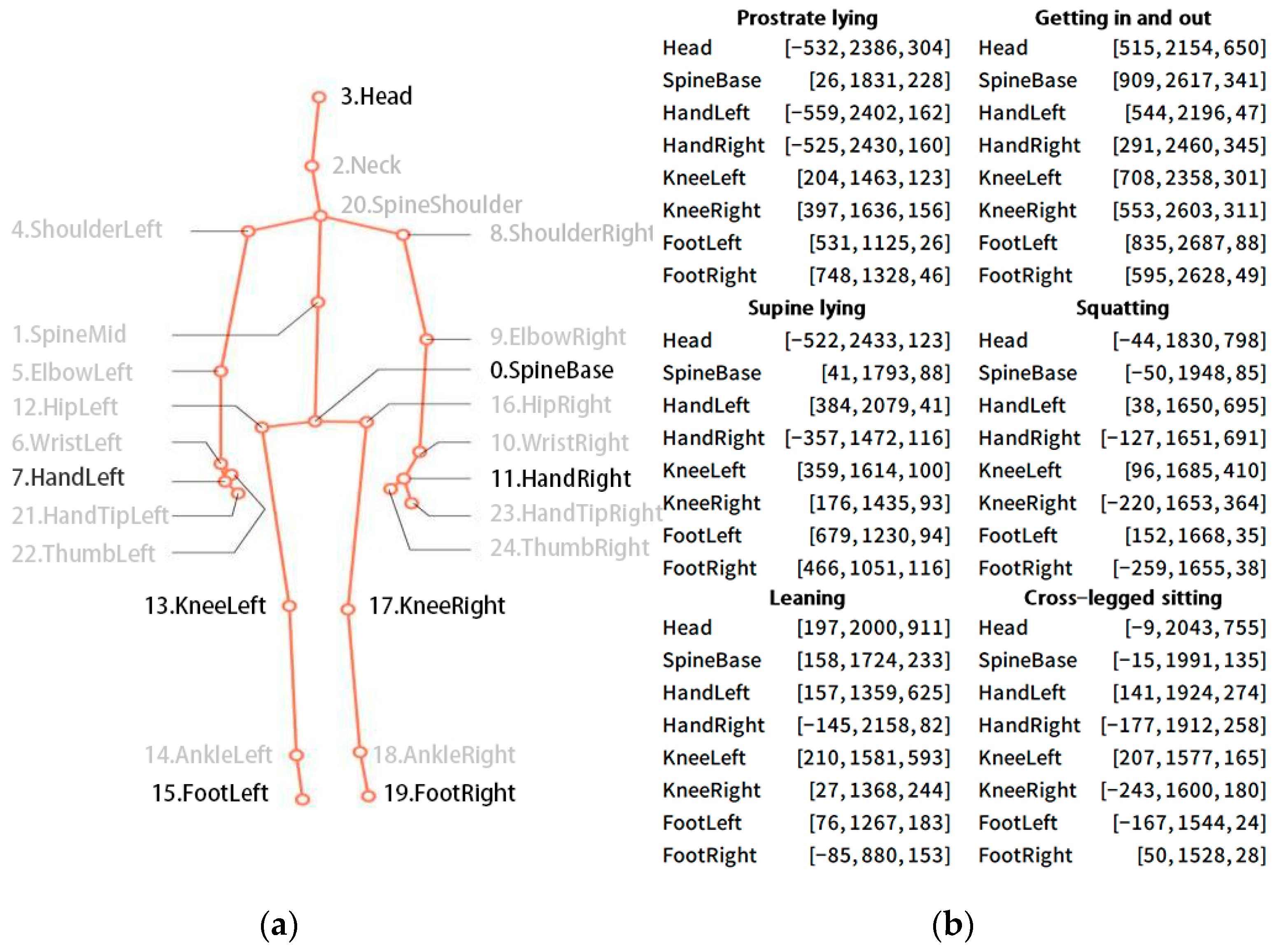
Our system employs a Kinect sensor to capture the user’s skeletal data for body tracking. The Kinect sensor is an affordable, portable, and non-intrusive device that accurately records human body movement features. It can capture up to 30 depth images per second. In 2012, Shotton et al. introduced the use of random forest regression to obtain the 3D coordinates of human joints []. Subsequently, the Kinect sensor was embedded with Shotton’s algorithm and has been widely used in the field of human tracking and action recognition []. This study builds upon previous work by utilizing a Kinect V2 and a plugin called Firefly to track the user []. This setup generates a digital dynamic skeleton and outputs Joint IDs along with their coordinates. The Kinect and Firefly can read data from 25 human skeletal points. We selected eight crucial joints: Head, SpineBase, HandLeft, HandRight, KneeLeft, KneeRight, FootLeft, and FootRight, to assess the morphology of the architectural robot (Figure 9a). During the data acquisition process, we recorded skeletal point data for six different postures described in Section 3.1 Figure 9b illustrates the spatial coordinates of these key skeletal points at various moments during one of the tests. Figure 10 depicts the process of a participant undergoing the test.
Figure 9. Acquiring spatial position data of human skeletal points using Kinect (a); recording of 3D coordinates of important skeletal points of the human body in six postures (b).
Figure 10. A participant performs six actions within the testing bench, and the dynamic data of the skeletal points under each action are collected and recorded.
After receiving the data of the skeletal points, we used GH Python2.7 to write programs to adjust the 3D coordinates of skeletal points in the digital model, thus positioning the skeletal points into a virtual model of the architectural robot. This process is divided into three steps, as depicted in Figure 11. First, the z-axis coordinates of the lowest skeletal point is set to zero, and the z-values of the other points are adjusted accordingly. This ensures that the person stands, sits or lies at the height of the ground where the architectural robot is located. Assuming that point P l o w is the lowest among all skeletal points, Kinect receives its initial coordinates as [ X l o w ,   Y l o w ,   Z l o w ] . Point P i represents another bone point with initial coordinates [ X i ,   Y i ,   Z i ] . After conversion, the coordinates of P l o w are adjusted to [ X l o w ,   Y l o w ,   0 ] , and the coordinates of P i are adjusted to [ X i ,   Y i ,   Z i Z l o w ] . Taking the frame in Figure 9b depicting the ‘cross-legged sitting’ posture as an example, the z value of FootLeft was the smallest among the 8 key points, measuring 24 (unit: mm). After the adjustment, its coordinate changed from [−167, 1544, 24] to [−167, 1544, 0]. At the same time, the z-values of other skeletal points also changed relative to FootLeft as the reference. For example, the coordinates of the point SpineBase were automatically adjusted from [−15, 1991, 135] to [−15, 1991, 111], and its z-value was also reduced by 24.
Figure 11. Adjusting the 3D coordinates of skeletal points in the digital model: the z-axis coordinates of the lowest skeletal point were set to zero, and the z-values of the other points were adjusted accordingly (a); both the x-value and y-value of the point SpineBase were set to 0, and the other points were adjusted accordingly (b); relocating the point head (c). The red annotations in the figure indicate coordinates that changed after each adjustment. The differently colored lines in (a,b) represent participants’ distinct postures: prostrate lying (black), getting in and out (red), cross-legged sitting (purple), leaning (pink), supine lying (blue), squatting (green).
The next step is to set both the x-value and y-value of the point SpineBase to 0, with other points adjusted accordingly. This adjustment positions the user in the center area enclosed by the architectural robot. We assume that the coordinates of SpineBase are transformed from [ X s b ,   Y s b ,   Z s b   Z l o w ] to [ 0 ,   0 ,   Z s b   Z l o w ] . Consequently, point P i moves from [ X i ,   Y i ,   Z i   Z l o w ] to [ X i   X s b ,   Y i   Y s b ,   Z i   Z l o w ] . To illustrate this, the frame depicting the “cross-legged sitting” posture in Figure 9b is used as an example. After the second modification, the coordinates of the point SpineBase were adjusted from [−15, 1991, 111] to [0, 0, 111]. Meanwhile, point FootLeft was relocated from [−167, 1544, 0] to [−152, −447, 0].
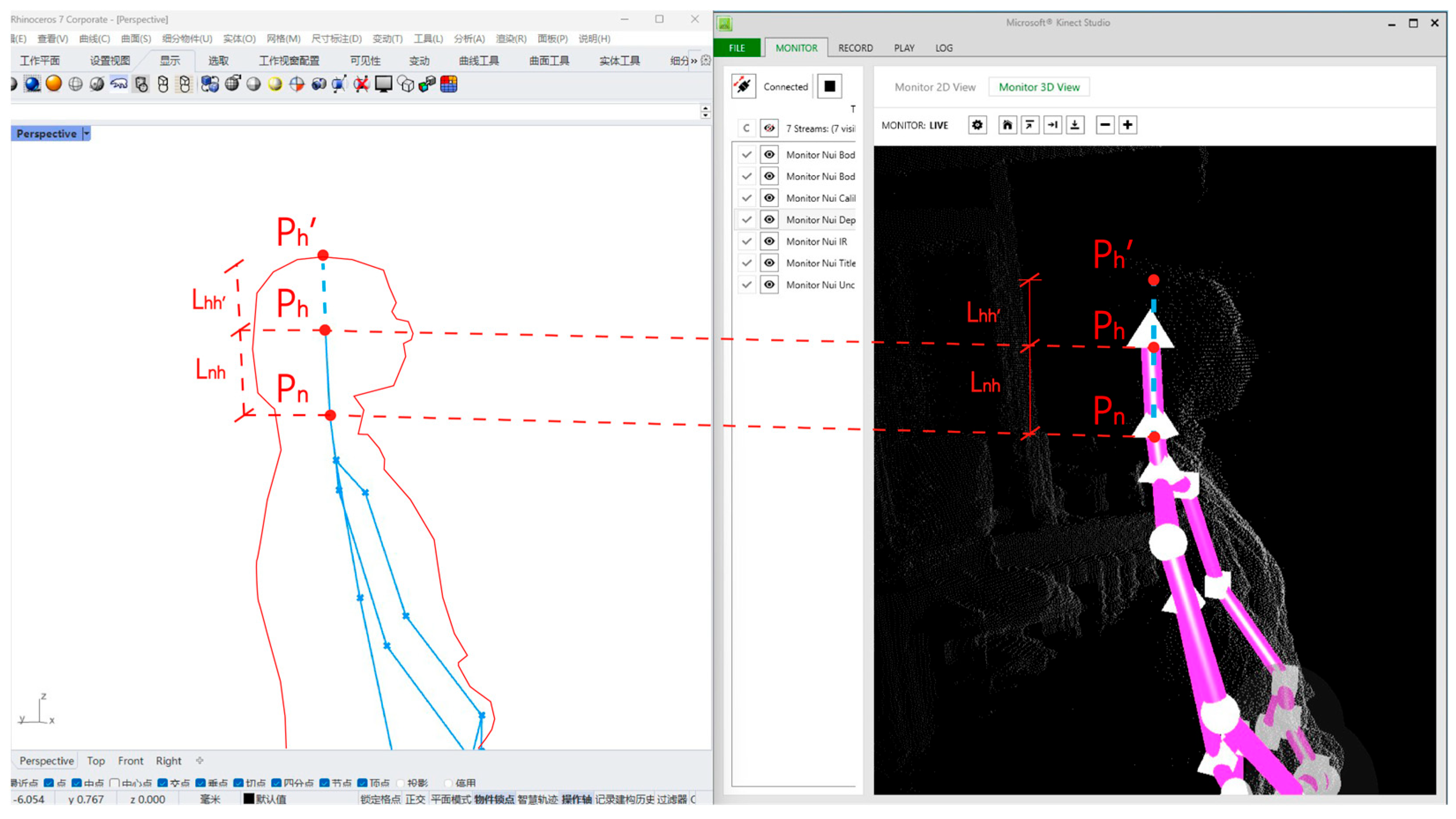
Since the head joint collected by Kinect represents the geometric center of the skull, while subsequent calculations require the participant’s head vertex rather than the geometric center, the obtained head joint needs to be further corrected. For ease of discussion, we denote the current neck joint as P n [ X n ,   Y n ,   Z n ] , the current head joint as P h [ X h ,   Y h ,   Z h ] , and the head vertex as P h [ X h ,   Y h ,   Z h ] . The distance between points P n and P h is L n h , and the distance between P h and P h is L h h . Figure 12 illustrates the exact relationships between these geometric elements. According to the relevant literature [], the average human head height is 210 mm, and the average neck height is 110 mm, from which the conversion factor between L n h and L h h can be calculated as 1.5:1. Points P n , P h , and P h lie on a straight line in space, and the vector between P n and P h is denoted as P n P h . Therefore, the spatial coordinates of P h can be calculated using the following method:
Figure 12. The spatial relationship between P n , P h   and P h . The left image shows the Rhino software interface, where red lines represent the human body outline, blue lines indicate skeletal lines, and blue dots mark key skeletal points. The right image displays the Kinect Studio software interface, where pink lines denote skeletal lines, and white spheres or triangular cones indicate the positions of skeletal points.
The vector between P n and P h is
P n P h = ( X h     X n ,   Y h     Y n ,   Z h     Z n )
The distance between P h and P h is
L h h = L n h / 1.5 = ( X h     X n ) 2 + ( Y h     Y n ) 2 + ( Z h     Z n ) 2 / 1.5
The unit vector of P h to P h is
u = u n h = X h     X n L n h , Y h     Y n L n h , Z h     Z n L n h
The coordinates of the head point after the adjustment are
P h = X h + L h h · u x , Y h + L h h · u y , Z h + L h h · u z
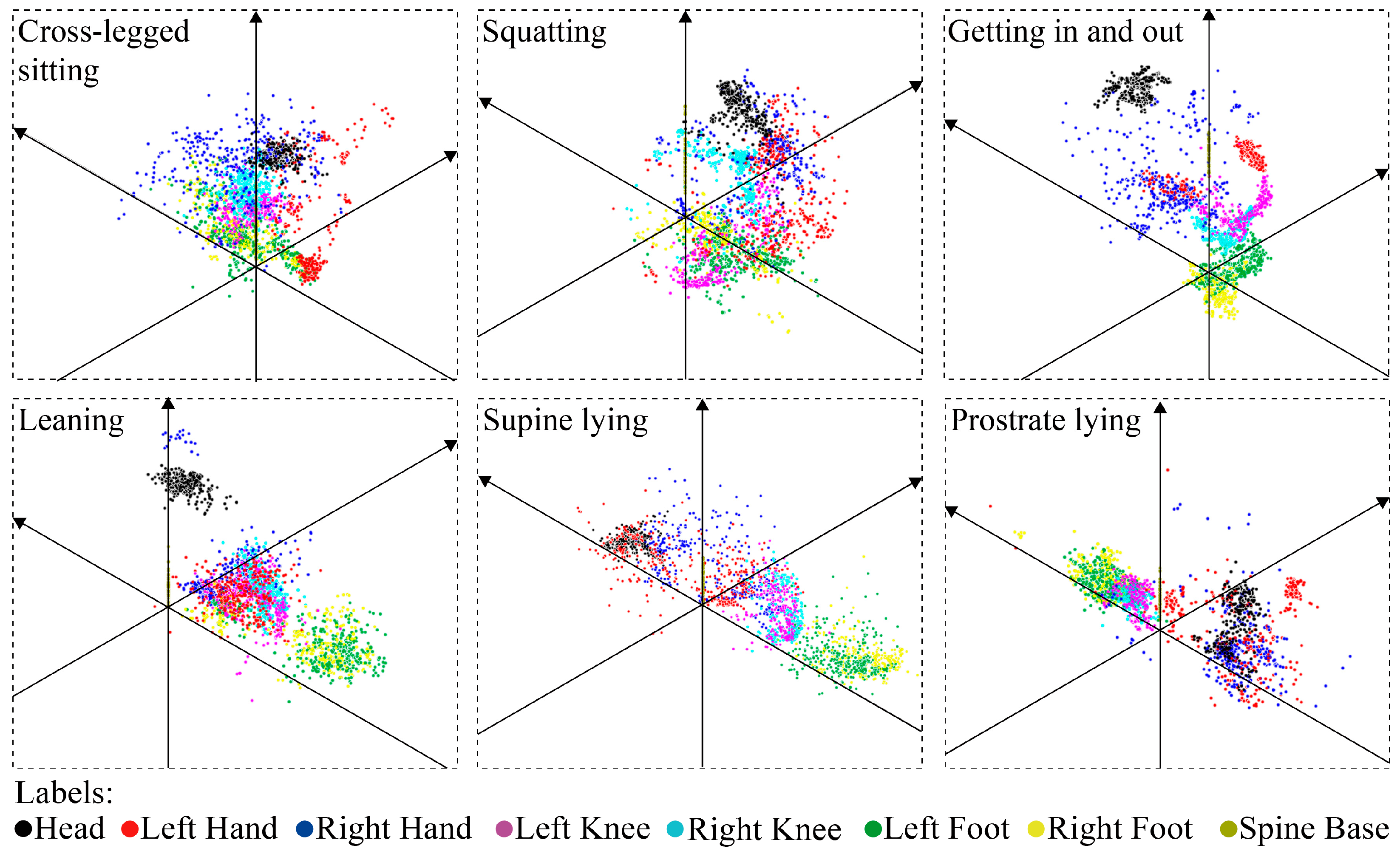
The programs mentioned above are used to adjust the 3D coordinates of the skeletal points for each of the six behaviors and to generate a customized spatial form suitable for its occupant. For each behavior, the skeletal point data acquisition process will last for 1 min. During this time, the user can assume any comfortable posture. For example, when obtaining data on “sitting cross-legged” behavior, the user could first open their arms and then rest their chin on one hand, if desired. We randomly selected 1 out of 30 frames acquired per second for data collection and transformation. This method acquires 480 skeletal point data per actions, with six actions totaling 2880 points of 3D coordinates. For example, Figure 13 displays a collection of vital skeletal points when a participant posed comfortably for six postures.
Figure 13. A collection of vital skeleton points of a participant in six postures.
These 2880 skeletal point data were used to compute the values of six form parameters for the architectural robot prototype. We set a rule to have the customized architectural robot wrap around as many of its user’s skeletal points as possible in order to make its form match the user’s behavior. We used genetic algorithms to achieve the goal of “wrapping more bone points in roughly the same volume.” The mathematical model of the optimal design is as follows:
M a x i m i z e : f P = f p 1 ,   p 2 ,   p 3 ,   p 4   , p 5 ,   p 6 = N N t
S u b j e c t   t o : 0.95 × V p V 1.05 × V p
N = t h e   n u m b e r   o f   s k e l e t o n   p o i n t s   w r a p p e d   b y   t h i s   s p a t i a l   m o r p h o l o g y ;
N t = t h e   t o t a l   n u m b e r   o f   s k e l e t o n   p o i n t s ;
V = t h e   v o l u m e   o f   t h e   s p a t i a l   m o r p h o l o g y   w r a p p e d   b y   t h e   a r c h i t e c t u r a l   r o b o t ;
V p = t h e   v o l u m e   o f   t h e   p r o t o t y p e   a r c h i t e c t u r a l   r o b o t .
Formula (5) P = p 1 ,   p 2 ,   p 3 ,   p 4 ,   p 5 ,   p 6 represents the design variables, i.e., the six parameters of the robot legs described in Figure 4; f P = N N t represents the optimization target, i.e., maximizing N N t . To prevent the shapes calculated by optimization from being out of scale, Formula (6) serves as a limiting condition in the optimization process.
The above mathematical model was calculated using the built-in operator Galapagos in Grasshopper []. The six design variables p 1 , p 2 , p 3 , p 4 , p 5 and p 6 were connected to the “Gene Pool” input terminal, f P was connected to the “Fitness” output terminal, the maximum optimization goal was set in the operator Galapagos, and the calculation was started (Figure 14). In the iterative optimization calculation, setting a higher number of iterations did not significantly improve fitness. Therefore, we collected skeletal point data from five participants in six postures and analyzed the fitness of the five participants’ data at different numbers of iterations. We found that the fitness was essentially stable at around 40 generations. Consequently, we set the number of iterations to 40, and the average computation time was only 5 min. Figure 15 shows the results of three examples of customized generation.
Figure 14. Optimization interface in operator Galapagos: the red dots are the points wrapped by the robot; the blue dots are the unwrapped points.
Figure 15. Participants with different behavioral habits generating corresponding robot forms.

3.3. Mobility: The Architectural Robots Can Follow Their Owners Like Puppies

We designed the gait planning of our architectural robot by referring to the locomotion of quadruped animals. When the robot is used as a temporary shelter, and its occupant finds a new campsite, it can follow its owner around like a puppy. The quadrupeds’ gait patterns are generated via the coordination between limbs and categorized into walk, trot, and gallop. Quadrupeds can achieve low-cost transport over a wide locomotion speed range by changing their gait patterns []. For instance, when quadrupeds “walk” at low speeds, their four legs lift in turn. When quadrupeds “trot” at middle speeds, their diagonal legs are raised and landed synchronously, i.e., the left front leg and right back leg move in unison, and the left back leg and right front leg move in unison. When quadrupeds “gallop” at high speed, their left and right legs move asymmetrically. Considering that architectural robots do not require high movement speeds, we chose the “walk” gait pattern as the paradigm for our quadruped robot. This gait is slower, but it provides high stability during locomotion and is easy to control.
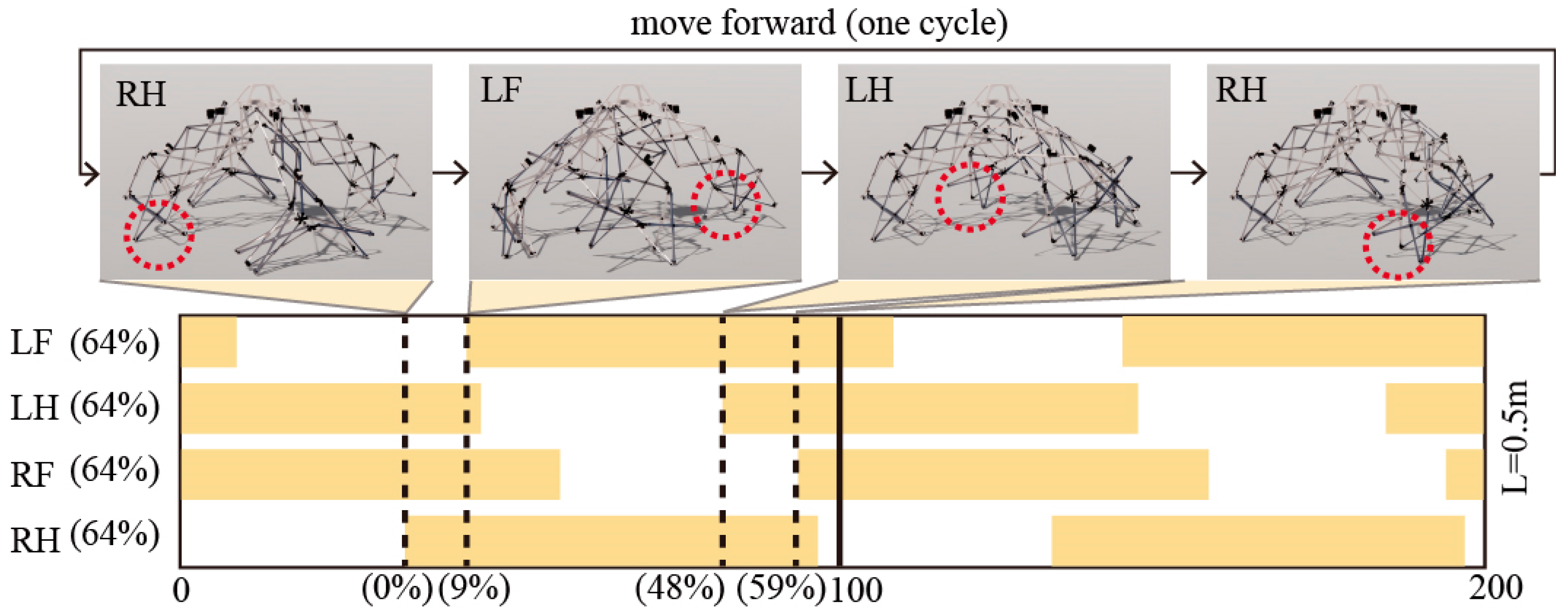
In the “walk” gait pattern, different leg movement sequences are observed in different quadruped animals []. Primates such as monkeys exhibit diagonal-sequence walking (D-S walk, Figure 16a), in which their legs touch down in the order of right hind (RH), left fore (LF), left hind (LH), and right fore (RF). In contrast, other quadrupeds, such as horses, exhibit lateral-sequence walking (L-S walk, Figure 16b), in which the feet touch down in the order of RH, RF, LH, and LF [,,,]. The crawling gait of human infants gradually changes from L-S walk to D-S walk during ontogeny []. We chose D-S walk as the inter-limb coordination for the architectural robot because its center of gravity is relatively more stable []. Figure 17 shows that in this study, the duty cycle for each leg in the quadruped robot’s gait cycle was 64%, indicating that each leg spends approximately 64% of the gait cycle in the support phase, maintaining contact with the ground to provide the necessary support force for the robot’s forward motion. This high duty cycle effectively enhances the robot’s walking stability, particularly during low-to-medium speed uniform linear motion. This mitigates the risk of insufficient support or tipping over, which can occur when the swing phase becomes excessively prolonged.
Figure 16. Gait diagram of quadruped locomotion observed in different animals: monkeys exhibit D-S walk (a) whereas horses exhibit L-S walk (b).
Figure 17. A cycle of architectural robot walking (The arrows in the diagram indicate the sequence in which the architectural robot’s four legs lift during movement: right hind (RH), left fore (LF), left hind (LH), and right fore (RF)). The dashed lines indicate the phase positions at which each leg enters the stance phase relative to the right front leg (RH) during one gait cycle. The solid black line in the figure represents one gait cycle.
Using the right rear leg (RH) as the reference leg, the phase distributions for the remaining three legs are front left leg (LF) at 9%, rear left leg (LH) at 48%, and front right leg (RF) at 59%. This phase distribution demonstrates reasonable gait coordination. LF and RH enter the support phase nearly simultaneously, forming diagonal support to enhance stability during the early gait cycle. LH lags RH by approximately half a cycle (48%), while RF lags by about 60%. This ensures that when RH is swinging or grounding, the other legs can effectively support the robot, maintaining at least two legs in contact with the ground at all times. This guarantees smooth and continuous motion.
Overall, this gait cycle features balanced duty cycles and a rational phase distribution, enabling stable quadrupedal robot locomotion while balancing power efficiency and support stability. This parameter design aligns with the kinematic characteristics of symmetrical quadrupedal gaits and provides a reliable foundation for subsequent gait optimization and control strategies.
The movement of the architectural robot is controlled by a bus servo control board and 12 bus servos. The bus servo control board is located at the core of the robot and includes a Bluetooth module, which allows the robot’s movements to be managed via a handle. To execute D-S walk and operate the robot, forward and turning motions are simplified into a series of action groups. These action groups are uploaded to the servo control board. When the user manipulates the robot using the handle, the signals from the action groups are transmitted to the control board through the Bluetooth module, activating the servos to enable the D-S walk movement. As shown in Figure 18, three bus servos control each leg of the robot. All servos are connected to the bus servo control board at the center using DuPont wires. Each of the 12 bus servos has a stall torque of 85 kg·cm. Servo I is located on the second segment of the leg and controls the angle between two edges of the X-units in that segment, facilitating the rotation of the X-units in other segments and managing the entire leg’s expansion and contraction. While retracting, Servo II, which is attached to the first segment, allows the leg to swing back and forth. Servo III is responsible for controlling the left and right rotation of the leg. The three servos in each leg work together harmoniously to execute the robot’s movements.
Figure 18. The robot’s legs can stretch (a), swing (b), or rotate (c) through the servos (The blue dashed line indicates the motion of the servo marked in red and its axis of rotation).
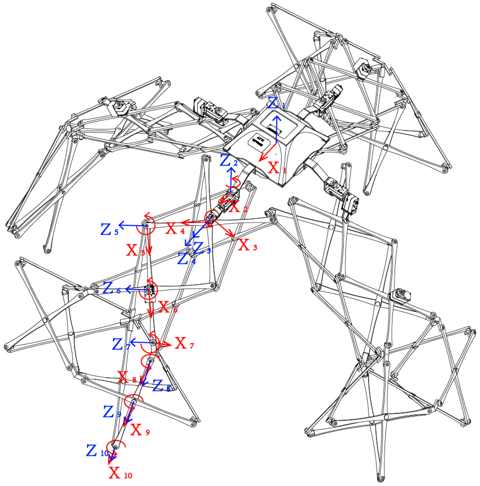
Research based on the standard Denavit–Hartenberg (DH) parameter method established a kinematic model for each support leg, as shown in Figure 19. Since a single support leg comprises multiple interconnected scissor mechanism joints, it forms a complex closed-chain system. Directly modeling all nodes as a whole would result in constraint redundancy and excessive computational complexity. Therefore, we extracted a representative motion chain from the closed chain and describe its link motion using the DH parameter method. This simplifies modeling while preserving the mechanism’s primary motion characteristics. Each leg is treated as a motion chain formed by ten serial rotary joints, extending from the body connection point to the end-effector (toe) position. Local coordinate systems are sequentially established on each link. The blue Z_i axis represents the rotational axis direction of each joint, while the red X_i axis is set perpendicular to the adjacent Z_i axis according to DH conventions.
Figure 19. Kinematics model of a single support leg. In the figure, X1, Z1–X10, and Z10 represent the local coordinate systems established for each joint based on the Denavit–Hartenberg parameter system.
This systematic parameterization allows the position and orientation of the toe to be expressed as functions of joint variables, laying the foundation for forward and inverse kinematic analysis. Defining the four standard DH parameters (a_i, α_i, d_i, θ_i) for each joint describes the spatial transformation between adjacent coordinate systems. This enables analytical modeling and simulation of the scissor mechanism’s overall motion. The calculated DH parameters are shown in Table 1.
Table 1. DH parameters for a single support leg.

4. Experimental Results and Discussion

4.1. “Scan–Generation–Fabrication” of an Experimental Architectural Robot

Based on the skeletal prototype of the architectural robot outlined in Section 3, one of the authors of this article acted as a customer who utilized the robot to fabricate a full-scale structure tailored to her body features and behavioral habits. The aim of this approach was to validate the feasibility of the methodology. The process included scanning the user’s skeletal points in various postures, which automatically generated six parameters for the architectural robot. The length of each unit in the robot’s legs and the angles between the directions of the multidirectional nodes were subsequently calculated. The rods for the X-units were provided in .dwg format for laser cutting, while the multidirectional nodes were supplied in .fbx format for 3D printing. These customized components were then integrated with electronic elements, such as batteries, bus servos, and servo controllers, to create a deployable and habitable architectural robot. The entire experimental process was independently conducted by the author’s team at the Digital Fabrication Lab of Tianjin University (Figure 20).
Figure 20. Data flow of the experimental architectural robot: scan–generation–fabrication.
This architectural robot weighs 6.4 kg. It features four legs composed of 48 X-shaped units, utilizing a total of 96 rods (Figure 21a). In this experimental setup, all rods were 3 mm thick and varied in length from 472.5 mm to 510 mm. The shapes of each rod were designed using NURBS curves, which extended to 10 mm at the nodes and tapered to 5 mm at their narrowest points. Each leg consisted of 24 rods, including 22 standard rods without rings and 2 specialized rods with rings (Figure 21b). The rods with rings were specifically designed for connection to servo I. In each pair of X-units, the rod with the larger ring (m-rod) was attached to the servo body via a 3D printed connector, while the rod with the small ring (n-rod) was attached to the servo’s rudder plate to control the angle between the two edges of the X-unit (Figure 21c).
Figure 21. The rods composing the architectural robot. Full-scale architectural robot (a); The rod forming one leg of the architectural robot (b); The X-Unit on one leg (c).
Two materials were tested for the fabrication of these rods: acrylic and steel. Acrylic sheets offer good machinability, high surface hardness, and an attractive appearance, and they are less prone to rust and corrosion. However, they are brittle and can crack or fracture under impact or pressure. Alloy structural steel, on the other hand, in addition to its advantages of high durability, corrosion resistance, and strength, is not prone to fracture was therefore selected as the final material for the manufacture of the architectural robot skeleton.
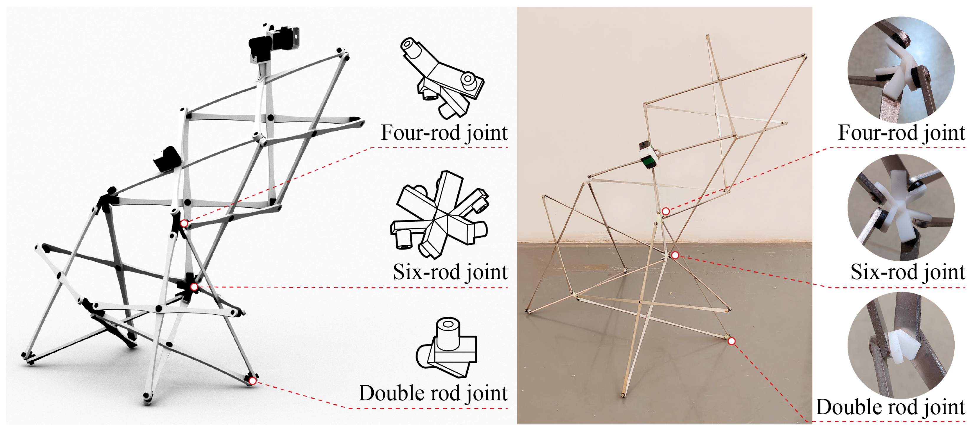
The architectural robot is equipped with 64 nodes that interconnect all X-units, comprising 4 six-way nodes, 12 four-way nodes, and 48 two-way nodes. We experimented with two materials for fabricating multi-directional nodes. First, we employed rigid photopolymer resin for 3D printing, incorporating acrylic flat pads to precisely align the top and bottom overlapping surfaces of the rods. These rods were securely fastened using 6mm round-head self-tapping screws with washers (Figure 22). While resin printing offered convenience and cost-effectiveness, this node design exhibited significant brittleness, insufficient stiffness, and susceptibility to aging. We then replaced the resin nodes with metal 3D-printed counterparts to enhance stiffness and stability (Figure 23).
Figure 22. Resin 3D-printed nodes.
Figure 23. Metal 3D-printed nodes.
The architectural robot’s core was 3D printed using a rigid light-cured resin, featuring specifically designed holes for attaching the legs. The connectors that link the core to the legs were also printed in hard resin using light-curing technology. These connectors were secured to the core and the servo using M2 round-head screws (Figure 24). Once the rods, nodes, and legs were fabricated, we assembled them to create the skeletal structure of the architectural robot (Figure 25).
Figure 24. The 3D-printed core of the architectural robot.
Figure 25. The skeletal structure of the architectural robot.
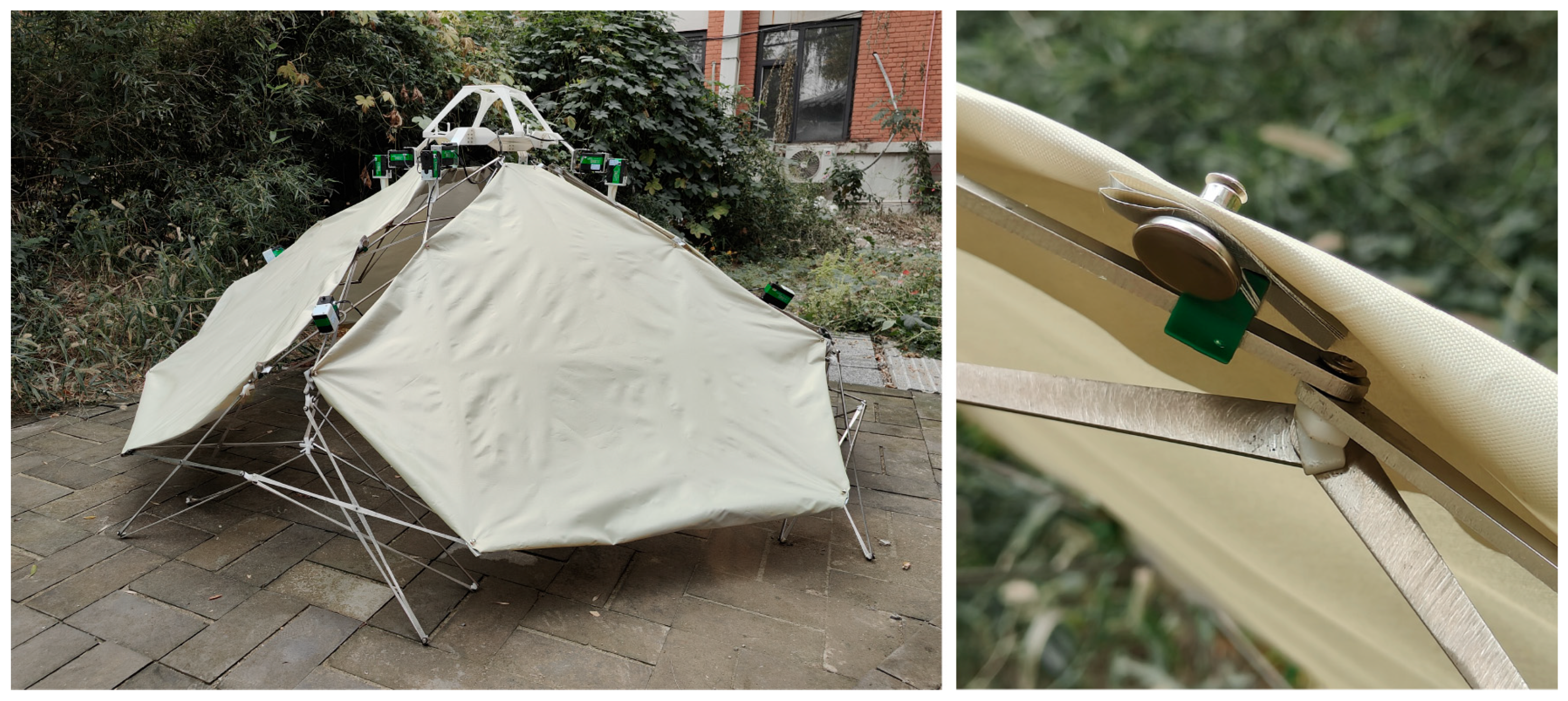
We completed the architectural robot by adding a cover cloth to the skeleton, which enhanced the sense of enclosure. We experimented with two different methods for attaching the cloth to the skeleton. Initially, we used four-sided elastic, a fabric made from a blend of polyester, spandex, and other highly elastic fibers. We sewed it onto the skeleton, intending for the cover cloth to be permanently attached without the need for additional assembly. However, we encountered limitations with the tension provided by the robot’s legs, making it difficult to stretch the elastic cloth. Subsequently, we adopted a different approach inspired by camping tents. We used 210D waterproof Oxford fabric for the cover cloth and sewed hooks directly onto it to connect to the skeleton. This method is simple, stable, and does not result in any loose parts (Figure 26).
Figure 26. The cover cloth on the skeleton enhances the sense of enclosure within the architectural robot.

4.2. Results and Discussions

The experimental results indicate that the architectural robot is deployable, habitable, and movable. In terms of unfolding performance, the spatial scissor structure allows each leg of the robot to expand from a tetrahedron into a three-dimensional, inverted Y-shape. Simultaneously, the entire architectural transforms from a compressed polyhedron with almost no internal space into a dome-shaped space that can accommodate basic human activities, increasing its volume to 4.1 times that of its folded state. In terms of habitation performance, the architectural robot enables the occupant to engage in essential daily behaviors, such as lying down, sitting, squatting, and leaning. Additionally, the spatial form enclosed by the robot aligns with the occupant’s behavioral habits. The spatial distribution of skeletal points for different behaviors defines six parameters of the robot’s form. An experimental participant reported that she could perform behaviors smoothly and comfortably. In terms of mobility performance, the architectural robot was capable of mimicking the gait of a quadrupedal animal, allowing it to move short distances across smooth, obstacle-free surfaces.
The experimental results indicate that the architectural robot requires further improvements in the following areas. Firstly, the stability of the robot needs to be enhanced. Although it can stand on the ground using its four legs for self-support after deployment in a laboratory setting, it may slip or even collapse when subjected to excessive horizontal loads, such as heavy rain, snow, or wind in outdoor environments. We hypothesize that this instability stems from insufficient horizontal friction at the leg landing points and inadequate structural strength. Future research plans include enhancing stability by adding rubber pads to the robot’s leg contact points to improve grip force, while simultaneously increasing the width and thickness of the rod components in the legs.
Secondly, the mobility of architectural robots needs to be improved. Although the robot was able to move slowly on a flat surface, it faced challenges in terms of coordination and agility. This study referenced papers related to the locomotion gaits of quadrupedal mammals and quadrupedal robots. However, due to the team members’ backgrounds in architecture, we were unable to conduct more quantitative analyses regarding gait stability, top/nominal speed, stance stability margin, energy consumption, power draw, and runtime under load. In future research, we plan to engage in interdisciplinary collaboration with scholars in mechanical engineering and robotics. Constraints will be imposed on member angles, node rotations, or manufacturability to enhance the feasibility of proposed solutions. Concurrently, we will further refine the evaluation of robotic motion systems, including DH parameters and footfall timing diagrams.
Thirdly, since only one Kinect V2 camera was used for posture capture, the single-view setup led to self-occlusion and inaccuracies in certain movements, affecting the subsequent optimization process. In future work, multi-view optical motion capture systems such as Qualisys will be considered to improve accuracy. These systems employ synchronized infrared cameras to provide complementary views, ensuring that occluded joints remain visible from at least one angle. Alternatively, when wearing sensors is impractical, vision-based reconstruction frameworks such as EasyMocap can provide a flexible, non-invasive solution for enhancing data reliability.
Fourthly, the design of skins for architectural robots also needs to be improved. Although we can quickly install the skin onto the robot’s skeleton, its aesthetic appeal, coverage, and level of personalization remain suboptimal. Future research could explore additional skin materials and installation methods to enhance the overall design. We could also consider automatically linking the skin’s color, texture, transparency, and other properties to the user’s personal preferences, further strengthening this architectural robot’s capabilities for customized personalization.
Finally, this study has only one physical construction sample, resulting in limited user feedback after actual use. Although we generated five architectural robots with distinct spatial form parameters in a virtual environment using body and behavioral data from different users, constrained by budget and time limitations, we selected only one for full-scale construction. In future research, we plan to construct additional physical prototypes to gather user feedback data and validate the feasibility of this robotic prototype. Concurrently, we will compare the deployment times required by users during initial operation versus after gaining proficiency, calculate averages and standard deviations, and refine the user reports accordingly.

5. Conclusions

The emergence of architectural robots as autonomous entities brings increased physical variability and expression to architecture, potentially enhancing alignment with human needs. With the growing accessibility and affordability of technological innovations, such as digital manufacturing, pervasive sensing, and mechanical actuation, habitable architectural robots are anticipated to become increasingly common.
This research marks a significant advancement in this domain by developing a prototype of a deployable and habitable robot that can be tailored to fit its occupant. It contributes to the field of architectural robotics in several ways. The first contribution of the developed prototype lies in its foldability. When folded, multiple robots can be arranged in a tessellated configuration, facilitating efficient bulk storage and transportation. When extended, it rapidly expands to accommodate its user. More importantly, the architectural robot supports a customized optimization method through a human–computer interaction design system. This system scans the user’s behavioral habits to generate a personalized geometry. This method leverages accurate body data instead of traditional user descriptions, resulting in a more precise outcome. Lastly, the architectural robot can move to an appropriate terrain independently without being carried by humans. Unlike conventional robots or tents in fixed locations, this robot can accompany its occupant and adapt to new environments.
We completed the entire workflow for a full-scale architectural robot, from scanning the user’s dynamic skeletal points to generating corresponding spatial forms, and finally constructing the physical structure. The experimental results demonstrate that the architectural robot is deployable, habitable, and movable. This project serves as a pioneering case that elucidates the process and methodology of architectural robots from design to fabrication. This work contributes to a foundational understanding of this emerging field and offers valuable insights for integrating architectural knowledge with robotic technology in future endeavors. In the future, we plan to pursue deeper interdisciplinary collaboration with fields including materials science, mechanical engineering, and robotics to enhance this robot’s gait stability, mobility performance, and overall strength.

Author Contributions

Conceptualization, H.W.; Resources, Z.X.; Data curation, Y.C.; Writing—original draft preparation, Y.Z. and P.R.; Funding acquisition, Y.Z. All authors have read and agreed to the published version of the manuscript.

Funding

This research was funded by National Natural Science Foundation of China (Grant Number: 52508023).

Data Availability Statement

The original contributions presented in this study are included in the article. Further inquiries can be directed to the corresponding author.

Conflicts of Interest

The authors declare no conflicts of interest.

References

  1. Gross, M.D.; Green, K.E. Architectural robotics, inevitably. Interactions 2012, 19, 28–33. [Google Scholar] [CrossRef]
  2. Dinevari, N.F.; Shahbazi, Y.; Maden, F. Geometric and analytical design of angulated scissor structures. Mech. Mach. Theory 2021, 164, 104402. [Google Scholar] [CrossRef]
  3. Huang, W.; Wu, C.; Hu, J.; Gao, W. Weaving structure: A bending-active gridshell for freeform fabrication. Autom. Constr. 2022, 136, 104184. [Google Scholar] [CrossRef]
  4. Duarte, J.P. A discursive grammar for customizing mass housing: The case of Siza’s houses at Malagueira. Autom. Constr. 2005, 14, 265–275. [Google Scholar] [CrossRef]
  5. Zhang, Z.; Guo, Z.; Zheng, H.; Li, Z.; Yuan, P.F. Automated architectural spatial composition via multi-agent deep reinforcement learning for building renovation. Autom. Constr. 2024, 167, 105702. [Google Scholar] [CrossRef]
  6. Price, C. The fun palace. Drama Rev. TDR 1968, 12, 127–134. [Google Scholar] [CrossRef]
  7. Maierhofer, M.; Soana, V.; Yablonina, M.; Suzuki, S.; Koerner, A.; Knippers, J.; Menges, A. Self-choreographing network: Towards cyberphysical design and operation processes of adaptive and interactive bending-active systems. In Proceedings of the 39th Annual Conference of the Association for Computer Aided Design in Architecture (ACADIA), Austin, TX, USA, 21–26 October 2019. [Google Scholar] [CrossRef]
  8. Deyong, S. Companion to the History of Architecture; John Wiley & Sons: Hoboken, NJ, USA, 2017; pp. 1–12. [Google Scholar] [CrossRef]
  9. Eastman, C.M. Adaptive Conditional Architecture. Institute of Physical Planning, Carnegie-Mellon University: Pittsburgh, PA, USA, 1972. [Google Scholar]
  10. Negroponte, N. Soft Architecture Machines; MIT Press: Cambridge, MA, USA, 1975. [Google Scholar]
  11. Sterk, T.E. Building upon Negroponte: A hybridized model of control suitable for responsive architecture. Autom. Constr. 2005, 14, 225–232. [Google Scholar] [CrossRef]
  12. Kroner, W.M. An intelligent and responsive architecture. Autom. Constr. 1997, 6, 381–393. [Google Scholar] [CrossRef]
  13. Attia, S. Evaluation of adaptive facades: The case study of Al Bahr Towers in the UAE. QSci. Connect 2017, 2017, 6. [Google Scholar] [CrossRef]
  14. Wigginton, M.; Harris, J. Intelligent Skins; Routledge: Oxford, UK, 2013; pp. 173–178. [Google Scholar]
  15. Droege, P.; Porta, S.; Salingaros, N. Intelligent Environments: Spatial Aspects of the Information Revolution; Elsevier: Amsterdam, The Netherlands, 1997. [Google Scholar]
  16. Oosterhuis, K. Programmable Architecture; L’Arcaedizione: Milan, Italy, 2002. [Google Scholar]
  17. Oosterhuis, K. Towards a New Kind of Building: Tag, Make, Move, Evolve; NAi: Rotterdam, The Netherlands, 2011. [Google Scholar]
  18. Bullivant, L. Jason Bruges: Light and space explorer. Archit. Des. 2005, 75, 79–81. [Google Scholar] [CrossRef]
  19. Floreano, D.; Nosengo, N. Tales from a Robotic World: How Intelligent Machines Will Shape Our Future; MIT Press: Cambridge, MA, USA, 2022. [Google Scholar] [CrossRef]
  20. Gray, J.; Hoffman, G.; Adalgeirsson, S.O.; Berlin, M.; Breazeal, C. Expressive, Interactive Robots: Tools, Techniques, and Insights Based on Collaborations. In Proceedings of the HRI 2010 Workshop “What Do Collaborations with the Arts Have to Say About HRI?”, Osaka, Japan, 2–5 March 2010. [Google Scholar]
  21. Green, K.E. Architectural Robotics: Ecosystems of Bits, Bytes, and Biology; MIT Press: Cambridge, MA, USA, 2016. [Google Scholar]
  22. De Aguiar, C.H.; Fateminasab, R.; Frazelle, C.G.; Scott, R.; Wang, Y.; Wooten, M.B.; Green, K.E.; Walker, I.D. The networked, robotic home+ furniture suite: A distributed, assistive technology facilitating aging in place. In Proceedings of the 2016 IEEE International Conference on Automation Science and Engineering (CASE), Fort Worth, TX, USA, 21–25 August 2016. [Google Scholar] [CrossRef]
  23. Oosterhuis, K. Hyperbodies: Towards an E-motive Architecture; Birkhäuser: Basel, Switzerland, 2003. [Google Scholar]
  24. Bier, H.H. Robotic buildings(s). Next Gener. Build. 2014, 1, 83–92. [Google Scholar] [CrossRef]
  25. Kilian, A. The flexing room architectural robot: An actuated active-bending robotic structure using human feedback. In Proceedings of the 38th Annual Conference of the Association for Computer Aided Design in Architecture, Mexico City, Mexico, 18–20 October 2018. [Google Scholar] [CrossRef]
  26. Grasshopper. Available online: https://www.grasshopper3d.com/ (accessed on 3 December 2024).
  27. Shotton, J.; Girshick, R.; Fitzgibbon, A.; Sharp, T.; Cook, M.; Finocchio, M.; Moore, R.; Kohli, P.; Criminisi, A.; Kipman, A.; et al. Efficient human pose estimation from single depth images. IEEE Trans. Pattern Anal. Mach. Intell. 2012, 35, 2821–2840. [Google Scholar] [CrossRef] [PubMed]
  28. Kinect v2 Sensor. Available online: https://learn.microsoft.com/zh-cn/shows/visual-studio-connect-event-2014/716 (accessed on 3 December 2024).
  29. Firefly. Available online: https://www.food4rhino.com/en/app/firefly (accessed on 3 December 2024).
  30. ISO 7250-1:2008; Basic Human Body Measurements for Technological Design. ISO: Geneva, Switzerland, 2008.
  31. Galapagos. Available online: https://www.grasshopper3d.com/group/galapagos (accessed on 3 December 2024).
  32. Hoyt, D.F.; Taylor, C.R. Gait and the energetics of locomotion in horses. Nature 1981, 292, 239–240. [Google Scholar] [CrossRef]
  33. Muybridge, E. Animal Locomotion: The Muybridge Work at the University of Pennsylvania, the Method and the Result; JB Lippincott Company: New York, NY, USA, 1888. [Google Scholar]
  34. Hildebrand, M. Symmetrical Gaits of Horses: Gaits can be expressed numerically and analyzed graphically to reveal their nature and relationships. Science 1965, 150, 701–708. [Google Scholar] [CrossRef] [PubMed]
  35. Hildebrand, M. Symmetrical gaits of primates. Am. J. Phys. Anthropol. 1967, 26, 119–130. [Google Scholar] [CrossRef]
  36. Hildebrand, M. Symmetrical gaits of dogs in relation to body build. J. Morphol. 1968, 124, 353–359. [Google Scholar] [CrossRef] [PubMed]
  37. Cartmill, M.; Lemelin, P.; Schmitt, D. Support polygons and symmetrical gaits in mammals. Zool. J. Linn. Soc. 2002, 136, 401–420. [Google Scholar] [CrossRef]
  38. Patrick, S.K.; Noah, J.A.; Yang, J.F. Interlimb Coordination in Human Crawling Reveals Similarities in Development and Neural Control With Quadrupeds. J. Neurophysiol. 2009, 101, 603–613. [Google Scholar] [CrossRef] [PubMed]
  39. Owaki, D.; Kano, T.; Nagasawa, K.; Tero, A.; Ishiguro, A. Simple robot suggests physical interlimb communication is essential for quadruped walking. J. R. Soc. Interface 2013, 10, 20120669. [Google Scholar] [CrossRef] [PubMed]
Disclaimer/Publisher’s Note: The statements, opinions and data contained in all publications are solely those of the individual author(s) and contributor(s) and not of MDPI and/or the editor(s). MDPI and/or the editor(s) disclaim responsibility for any injury to people or property resulting from any ideas, methods, instructions or products referred to in the content.

Article Metrics

Citations

Article Access Statistics

Multiple requests from the same IP address are counted as one view.