Article

Systematic Method for Identifying Safety and Security Requirements in Autonomous Driving: Case Study of Autonomous Intersection System

Institute for Engineering Design, Technische Universität Braunschweig, Herrman-Blenk Strasse 42, 38108 Braunschweig, Germany
*
Author to whom correspondence should be addressed.
Appl. Syst. Innov. 2025, 8(6), 168; https://doi.org/10.3390/asi8060168 (registering DOI)
Submission received: 3 July 2025 / Revised: 12 August 2025 / Accepted: 29 October 2025 / Published: 31 October 2025
(This article belongs to the Section Control and Systems Engineering)

Abstract

This paper presents a systematic methodology for identifying and integrating safety and security requirements in autonomous driving systems, demonstrated through the case of an autonomous intersection. The study focuses on modeling the intelligent intersection using the MBSE Grid Framework, the SysML modeling language, and the Cameo Systems Modeler tool. Two specific use cases are modeled to illustrate the system’s functionality. A multidisciplinary approach is developed to incorporate safety and security requirements into the system model, combining theoretical foundations with practical implementation techniques. The methodology includes both a generalizable framework and domain-specific strategies tailored to autonomous driving. The proposed approach is applied and critically evaluated using the intelligent intersection as a case study. By extending SysML to systematically address safety and security concerns, the work contributes to the development of safer and more efficient autonomous transportation systems. The results provide a foundation for future research and practical applications in the field of intelligent mobility and cyber–physical systems.

1. Introduction

The rapid and continuous development of the automotive industry, particularly in the field of autonomous driving, holds considerable potential for transforming the entire mobility and transport infrastructure. This ongoing technological change goes beyond vehicle automation itself and encompasses the entire mobility ecosystem, in which intelli-gent transport systems are starting to take an ever more significant role. These systems are increasingly recognized as relevant actors of this transformation, as they promise to improve traffic management, reduce congestion, and increase overall efficiency, while also improving the safety and well-being of all road users, including drivers, passengers, pedestrians, and cyclists. Despite these advances, the increasing complexity and interconnectivity of such systems introduce significant challenges in the domains of safety and security. This paper addresses these issues by presenting a structured approach for identifying and analyzing safety and security requirements for an autonomous intersection system.
To meet this need, the paper introduces a methodology grounded in Model-Based Systems Engineering (MBSE) and based on the guiding normative Safety and Security standards of the automotive field, with the aim of facilitating the systematic identification, classification, and iterative refinement of safety and security requirements of intelligent interaction systems. By combining the structured perspective afforded by the MBSE Grid with a method-specific tailoring, the proposed method enables the systematic identification, classification, and iterative refinement of safety and security requirements across multiple abstraction layers. The findings and methods discussed in this paper are intended to advance current practices in safety and security engineering for autonomous in-tersection systems and to provide a foundation for future research on scalable, standards-aligned MBSE-based methods in intelligent transportation systems.

2. State of the Art

2.1. Systems Engineering

Autonomous intersections require systematic coordination of complex interactions among vehicles, pedestrians, and cyclists. Systems Engineering (SE) provides an interdisciplinary framework for developing such systems, integrating requirements management, analysis, testing, and validation with project coordination [1]. The V-Model, a structuring framework that enables and supports the application of SE methodologies, aligns development phases with corresponding tests in a V-shaped process [2], as defined in VDI 2206 [3]. It comprises design (requirements, architecture, specification), implementation (development), and validation (testing from components to full system), ensuring traceability and system integrity [4].

2.1.1. Model Based Systems Engineering

MBSE represents a paradigm shift from traditional Systems Engineering by replacing document-centric processes with model-driven development [5]. According to INCOSE, MBSE formalizes modeling to support requirements, design, analysis, verification, and validation throughout the system lifecycle. Central to MBSE are system models, which offer interdisciplinary insights and guide development activities [6]. These models encompass system requirements (functional and non-functional), architecture (hardware, software, data flow), and behavior (responses to inputs, output generation), enabling simulation and analysis to validate functionality [7]. MBSE is grounded in system theory and structured around three elements: language, tool, and method. The method defines the modeling framework and scope, the language provides formal syntax and semantics, and the tool enables model creation and analysis [8].

2.1.2. MBSE Grid Method

The MBSE-Grid approach by Morkevičius et al. provides a structured method for modeling systems and requirements using SysML. Based on analyses of established MBSE frameworks [9], it organizes system modeling into a matrix where rows represent abstraction levels (Problem and Solution) and columns correspond to the four MBSE pillars: Requirements, Behavior, Structure, and Parametrics [10]. The Problem domain includes a Blackbox view (stakeholder needs, system context, use cases, MoEs) and a Whitebox view (system requirements, functional analysis, subsystem behavior, logical interfaces). The Solution domain defines the implementation layer: component-level requirements, structure, behavior, and parameters [10]. The MBSE-Grid, shown in Figure 1, enhances clarity, cross-domain collaboration, and cost-efficiency but requires modeling expertise and tool proficiency. For the autonomous intersection case, the framework was adapted: “Logical Subsystem Communication” → “Logical Architecture”, “Component Assembly” → “Component Structure”, and the “Parametrics” pillar was omitted. The modified grid structures system modeling across three levels: the full intersection system, its subsystems, and individual components [10].

2.2. Safety and Security Engineering

Advancing technologies have increased system complexity, particularly in autonomous mobility, where vehicles, infrastructure, and communication networks form cyber–physical systems (CPSs). CPSs integrate software, hardware, and mechanical components to link digital and physical domains, requiring meticulous planning and implementation to avoid safety-critical failures [11]. In highly automated driving, Safety and Security are critical, interrelated aspects, defined, respectively, by ISO 26262 and ISO/SAE 21434 [12,13,14]. Safety addresses physical safety and accident prevention through functional reliability, hazard analysis, risk mitigation, and robust system design [13,15]. Safety engineering involves secure hardware, redundancy, validation, and testing to prevent failures. Security, in contrast, protects against intentional threats such as cyberattacks or data manipulation. Security engineering ensures system confidentiality, integrity, and availability through threat identification, risk assessment, and countermeasure implementation as defined in ISO/SAE 21434 [12,14,16]. Both disciplines are essential for the safe, resilient operation of autonomous transportation systems. Safety and Security as a concept has the aim to protect relevant assets against failures (safety) and threats (security) by eliminating vulnerabilities, thus minimizing the risk of a malfunction or compromise of the system [17,18,19].

2.2.1. Requirements Engineering for Safety and Security

In cooperative highly automated driving, the integration of Safety and Security is essential to ensure traffic participant safety, vehicle protection, and system integrity. Treating these aspects in isolation neglects interdependencies and impairs development efficiency. Instead, consistent, traceable, and testable handling of Safety and Security requirements requires integrated, methodical approaches [20]. Methods such as Common Criteria from IT security can be adapted to automotive contexts, supported by semiformal specifications and toolchains to manage complexity. Interdependencies must be addressed early in requirements elicitation and maintained throughout the development lifecycle—including design, implementation, and continuous risk monitoring. The Safety and Security engineering process can be effectively aligned with the V-Model [20].

2.2.2. Safety Engineering Methods

HARA [13] identifies and evaluates hazards early in development to define safety goals and derive Automotive Safety Integrity Levels (ASIL A–D), based on severity, probability, and controllability. FMEA [21] systematically detects potential failure modes, their causes and effects, and prioritizes mitigation actions through structured steps—planning, functional analysis, risk evaluation, and optimization—documented in a standard form. FTA [22] applies a top-down deductive approach, mapping fault logic from a top event to basic causes using AND/OR gates. It supports both qualitative and quantitative risk analysis by propagating failure probabilities through the tree [13]. HAZOP [23,24] uses guide words (e.g., “more”, “less”, “none”) and parameters (e.g., pressure, flow) to systematically identify process deviations, their causes, and impacts. While resource-intensive, it excels at uncovering hidden hazards in industrial systems.

2.2.3. Security Engineering Methods

Threat Modeling, developed by Microsoft, is a structured approach for identifying and mitigating software security risks throughout development [25]. It models application architecture, data flows, and trust boundaries, and uses the STRIDE framework (Spoofing, Tampering, Repudiation, Information Disclosure, Denial of Service, Elevation of Privilege) to categorize threats. The SDL Threat Modeling Tool supports developers in automating and managing threat identification. Threat modeling is iterative and supports both proactive and reactive security strategies [25]. TARA is a systematic method for cyber risk analysis, structurally aligned with the ISO 26262 HARA process. It involves identifying assets, threats, and operational scenarios, followed by risk evaluation and the assignment of cybersecurity levels analogous to ASILs. Final steps include defining cybersecurity goals based on prioritized risks [14,26].

2.2.4. MBSE Based Approaches to Safety and Security Engineering

Recent research highlights the application of Model-Based Systems Engineering (MBSE) methods for eliciting and validating safety and security requirements in autonomous intersection systems, yet also reveals significant gaps, as shown in Table 1.
Early contributions, such as Wuthishuwong et al., used discrete mathematical models integrated with vehicle-to-infrastructure (V2I) communication to plan collision-free trajectories, demonstrating how formalized system models can be used to derive and verify basic safety properties like collision avoidance and minimal stops [27]. More recent efforts by Wang et al. employ SysML to model the architecture of cyber–physical intersection systems, incorporating Failure Mode and Effects Analysis (FMEA) into the MBSE workflow to identify system-level failure modes and refine the architecture accordingly [28]. These studies show growing MBSE maturity but primarily focus on safety in relatively controlled intersection environments. Security requirements—especially those arising from adversarial threats—are less frequently modeled and often handled separately from safety. To address this, Japs et al. introduced the SAVE method, integrating safety and security co-engineering through SysML-based workshops to identify security threats that can impact safety early in the design process [29]. Mažeika and Butleris further extended SysML with a security profile to enable systematic modeling of threats, controls, and mitigations, yet their framework, MBSEsec, was validated only on in-vehicle systems rather than infrastructure or intersection contexts [30]. In addition to MBSEsec, Mažeika and Butleris also proposed a UML-based security profile that conforms to common cybersecurity standards and allows integration of security analysis into MBSE workflows [31]. Their approach focuses on aligning security requirements engineering with SysML through a dedicated profile structure and has been demonstrated using a hybrid vehicle case study. However, this method, too, has not yet been applied to intersection-level infrastructure or evaluated in safety–security co-engineering contexts. Piątek et al. propose embedding cybersecurity patterns such as intrusion detection directly into MBSE safety models, demonstrating how reusable security elements can be integrated without compromising safety-critical functions, though again, the case studies remain centered on single-vehicle systems like emergency braking [32]. Nolte et al. contribute an MBSE-based method that explicitly aligns functional safety and cybersecurity requirement elicitation with ISO 26262 and ISO/SAE 21434 standards. Using SysML and the CAMEO environment, they develop a structured metamodel built on the MagicGrid framework and demonstrate its applicability through a case study in the automotive domain [13,14,19]. Although the method enhances traceability and harmonization between safety and cybersecurity goals, it remains focused on E/E system-level modeling and lacks domain-specific validation for intersection scenarios. Overall, despite promising approaches to co-modeling safety and security, current research still lacks comprehensive MBSE frameworks tailored specifically to the unique challenges of autonomous intersection systems, including dynamic multi-agent coordination, heterogeneous V2X interfaces, and real-time threat response, representing a key area for future investigation.

2.3. Research Questions

Based on the analysis of the current literature in Section 1 the following aims are defined for this paper:
RQ 1: How can an MBSE model of an autonomous intersection be implemented with a specific focus on safety and security engineering aspects?
RQ 2: How can a generally applicable method for the safety and security engineering of autonomous traffic systems be derived from the modeling process, fulfilling all parameters analyzed in Table 1?
The aim is to answer these questions by developing an MBSE-based intersection-system model, developing a method to identify safety and security requirements based on existing methods. As the last step, the developed method will be tested and evaluated on the previously developed intersection system model.

3. Development of the Intersection System Model

This section presents the system model of an intelligent intersection for autonomous driving, developed using the Cameo Systems Modeler by Dassault Systèmes. The system components are first described, followed by the modeling of each cell of the modified MBSE grid.

3.1. System Elements

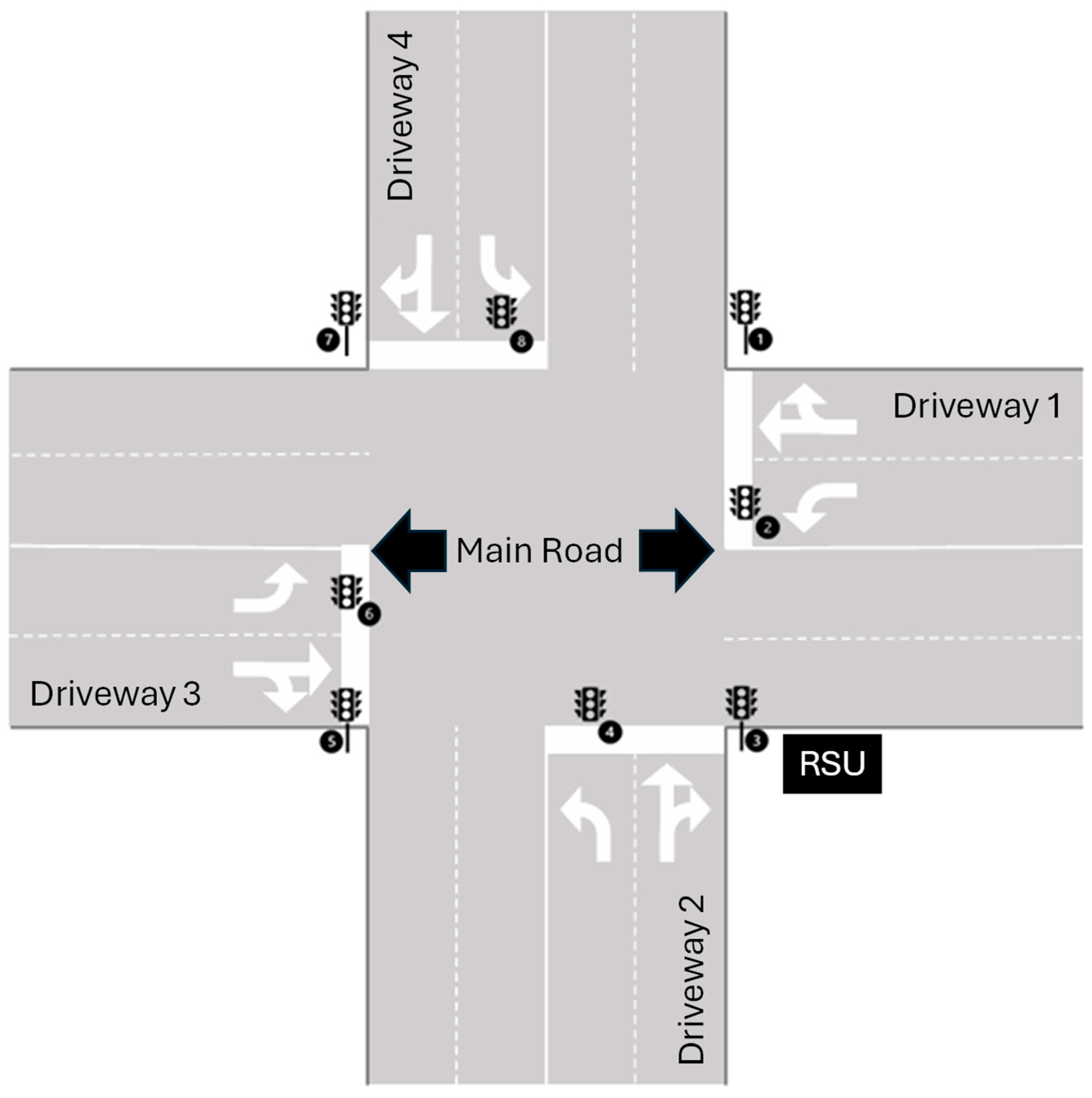
Intersections are critical components of road networks, essential for traffic regulation and safety. This study focuses on an intelligent intersection system designed for interaction with autonomous vehicles to optimize traffic flow, enhance safety, and reduce environmental impact. The system, as shown in Figure 2, comprises sensors, a Roadside Unit (RSU), and a traffic signal system (TSS), and interfaces with vehicles, emergency services, traffic management centers (TMCs), pedestrians, and cyclists, based on the components of an intelligent intersection described by Lee et al. [33].
The RSU (ITS Roadside Station) acts as a communication interface between infrastructure and vehicles, collecting and distributing traffic data (e.g., speed, direction, signal state) [34]. Sensors include cameras, radar, LiDAR, and inductive loops to detect vehicles, pedestrians, and traffic volume [35]. The TSS dynamically adjusts signal phases based on real-time sensor data via SPaT messages (Signal Phase and Timing) using J2735 standard [35,36]. The TMC (ITS Central Station) processes multi-source data (e.g., floating car data, signal controls) for centralized traffic monitoring and control, integrating with services like emergency response and parking systems [34]. Autonomous vehicles and AEVs (Autonomous Emergency Vehicles) interact with the intersection via V2X communication, allowing adaptive routing and prioritization during emergencies. Pedestrians and cyclists are detected via sensors and integrated into traffic control logic to ensure safety.

3.2. Framework Development

The MBSE-Grid approach is used to structure the overall system model. The model is organized using the Model Browser and the MBSE-Grid diagram. Four main packages are created: one contains the package diagram representing the grid, enabling intuitive navigation via interlinked elements; the other three represent the MBSE pillars (Requirements, Behavior, and Structure), each divided into three sub-packages reflecting the corresponding views.

3.3. MBSE Modeling—Black Box Problem Level

At the beginning of the modeling process, the entire system of the intelligent intersection is considered. This involves defining and modeling the needs of the stakeholders, the use cases and the system context.

3.3.1. Stakeholder Needs

The stakeholder needs analysis begins with identifying all relevant stakeholders of the intelligent intersection system, followed by a structured evaluation of their specific needs. Key system components—RSU, sensors, and TSS—support traffic detection and control. Stakeholders include infrastructure providers (e.g., traffic authorities, component manufacturers) seeking reliable traffic regulation, as well as users such as autonomous vehicles, emergency vehicles, pedestrians, and cyclists, each with needs related to safety, efficiency, and accessibility. The Traffic Management Center (TMC) is another critical stakeholder, requiring accurate real-time data to optimize traffic control strategies. Comprehensive consideration of all stakeholder needs supports robust requirements definition and more effective system design. These needs are illustrated in a SysML requirements diagram, as shown in Figure A1.

3.3.2. Use Cases

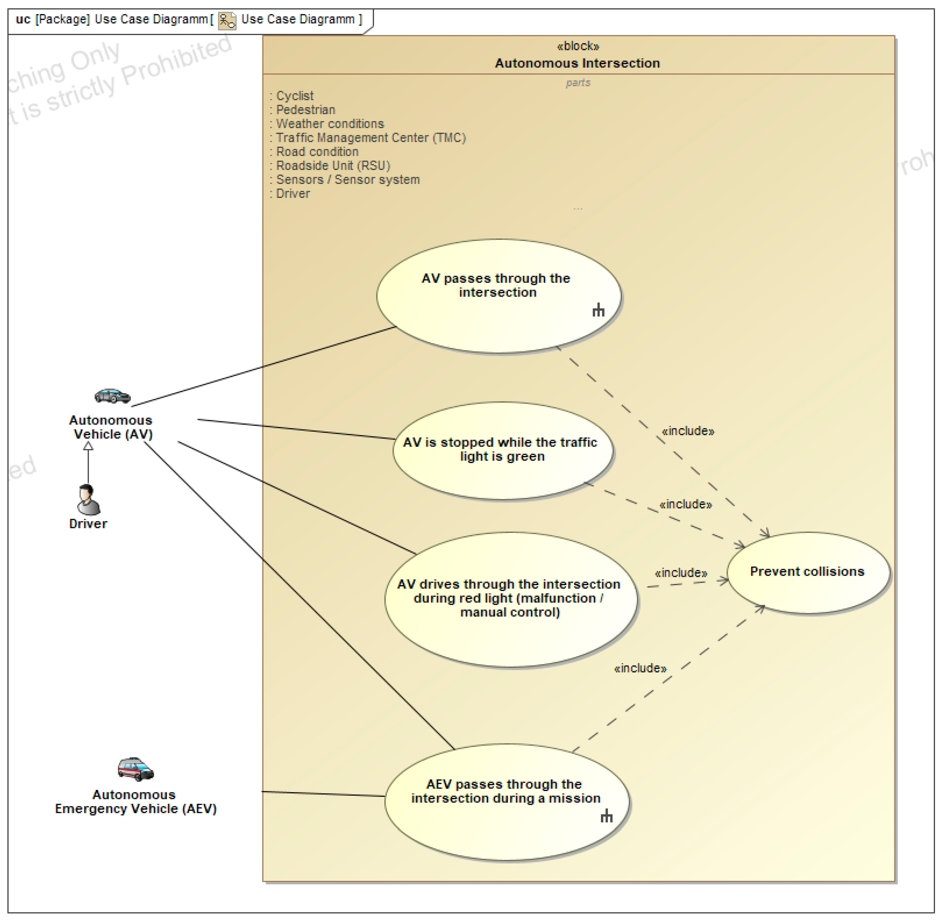
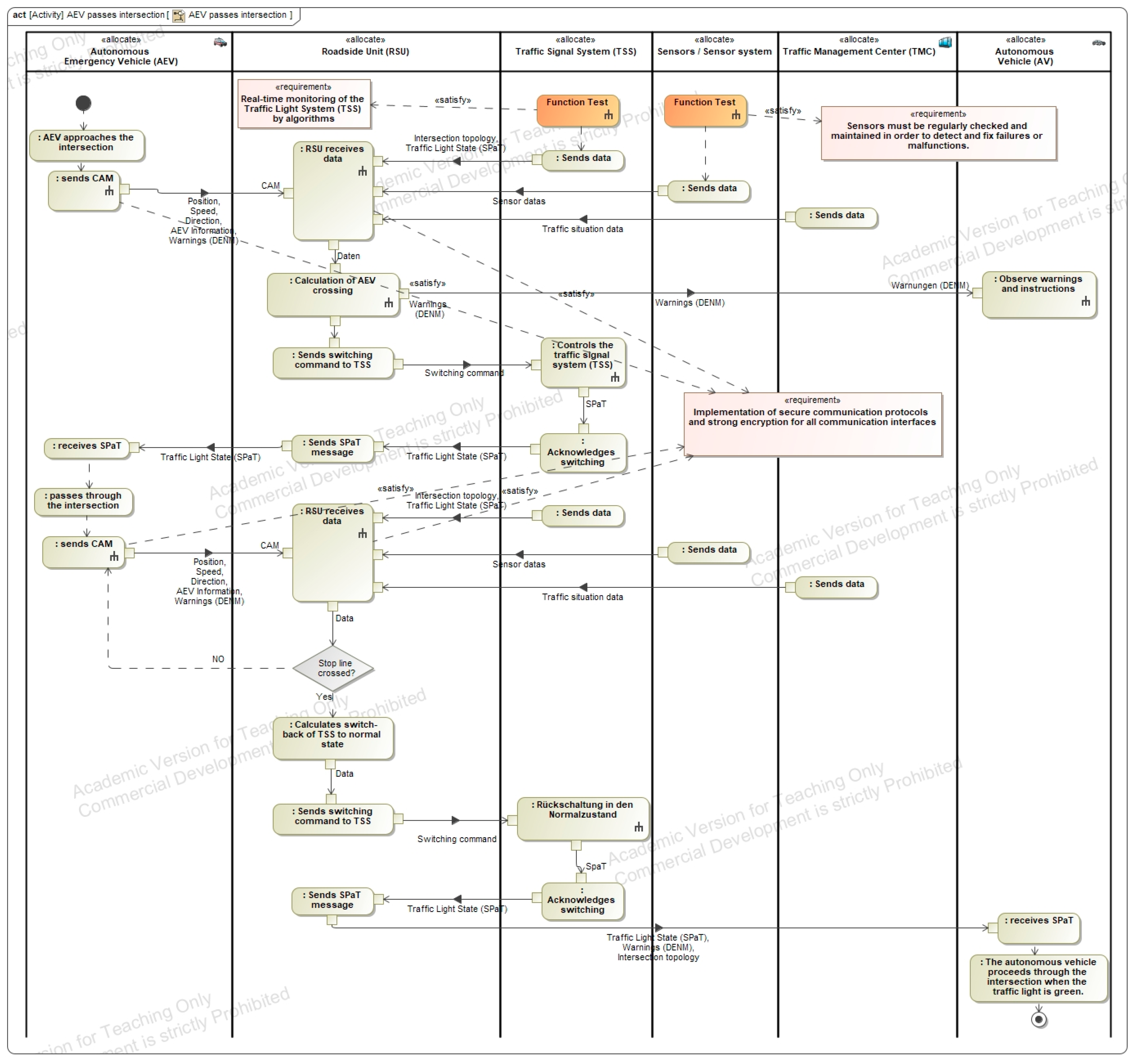
Following the identification of stakeholder requirements, key use cases for an intelligent intersection system are modeled, focusing on interactions with autonomous vehicles (AVs) and autonomous emergency vehicles (AEVs). Use cases include regular intersection traversal by AVs, handling of AV malfunctions (e.g., stopping at green or running red lights), and prioritized passage of AEVs during active deployment. These scenarios are visualized using use case and activity diagrams, offering detailed insights into the system’s dynamic behavior. Particular focus is given to the AEV use case, which is modeled to cover two primary traffic scenarios: traversal during longitudinal flow and during cross-traffic. AEVs communicate with the Roadside Unit (RSU) via Cooperative Awareness Messages (CAMs), providing data such as location, speed, heading, and urgency level. The RSU integrates this with sensor data, Signal Phase and Timing (SPaT) messages from the traffic light system, and data from the Traffic Management Center (TMC) to compute optimized signal plans. Relevant signal groups are set to green while others are blocked, and all nearby road users receive safety notifications. After the AEV clears the intersection, normal signal operations resume. This generalized use case approach avoids redundant modeling for individual scenarios and ensures adaptive, efficient, and safe intersection management across diverse traffic conditions, enhancing both system flexibility and real-world applicability, as shown in Figure A2 and Figure A3.

3.3.3. System Context

The system context of an intelligent intersection defines its interfaces and interactions with external elements. The intersection functions as the central system, with all communication and coordination converging at this point. It interacts with various subsystems, including autonomous vehicles that communicate via V2X technology to exchange positional and directional data for optimized traffic flow. Autonomous emergency vehicles require prioritization by the system in real-time to ensure rapid passage through the intersection. Pedestrians and cyclists, although passive participants, must be detected and considered in traffic control strategies. The system must also adapt to environmental influences such as weather conditions and road surface states, which affect visibility and mobility. These factors demand dynamic adjustment of traffic control to maintain safety and efficiency. Additionally, the traffic management center (TMC) acts as a supervisory authority, providing control instructions and receiving continuous data updates from the intersection system. This integrated context model ensures situational awareness and responsiveness, essential for reliable operation in connected, automated traffic environments, as shown in Figure A4.

3.4. MBSE Modeling—White Box Problem Level

Following the system-level analysis of the intelligent intersection, the focus shifts to the modeling of its subsystems. The process begins with the development of the functional architecture, followed by the definition of the logical architecture, and concludes with the specification of the system requirements. This hierarchical approach ensures a structured and detailed representation of system behavior, structure, and constraints.

3.4.1. System Requirements

The derivation of system requirements is informed by stakeholder needs as well as the system’s functional and logical architectures. Primarily derived from stakeholder expectations, the requirements are categorized into functional, non-functional, regulatory, environmental, and maintenance and support domains. Specific requirements include, for example, vehicle integration and the detection of pedestrians and cyclists, as shown in Figure A5.

3.4.2. Functional Analysis

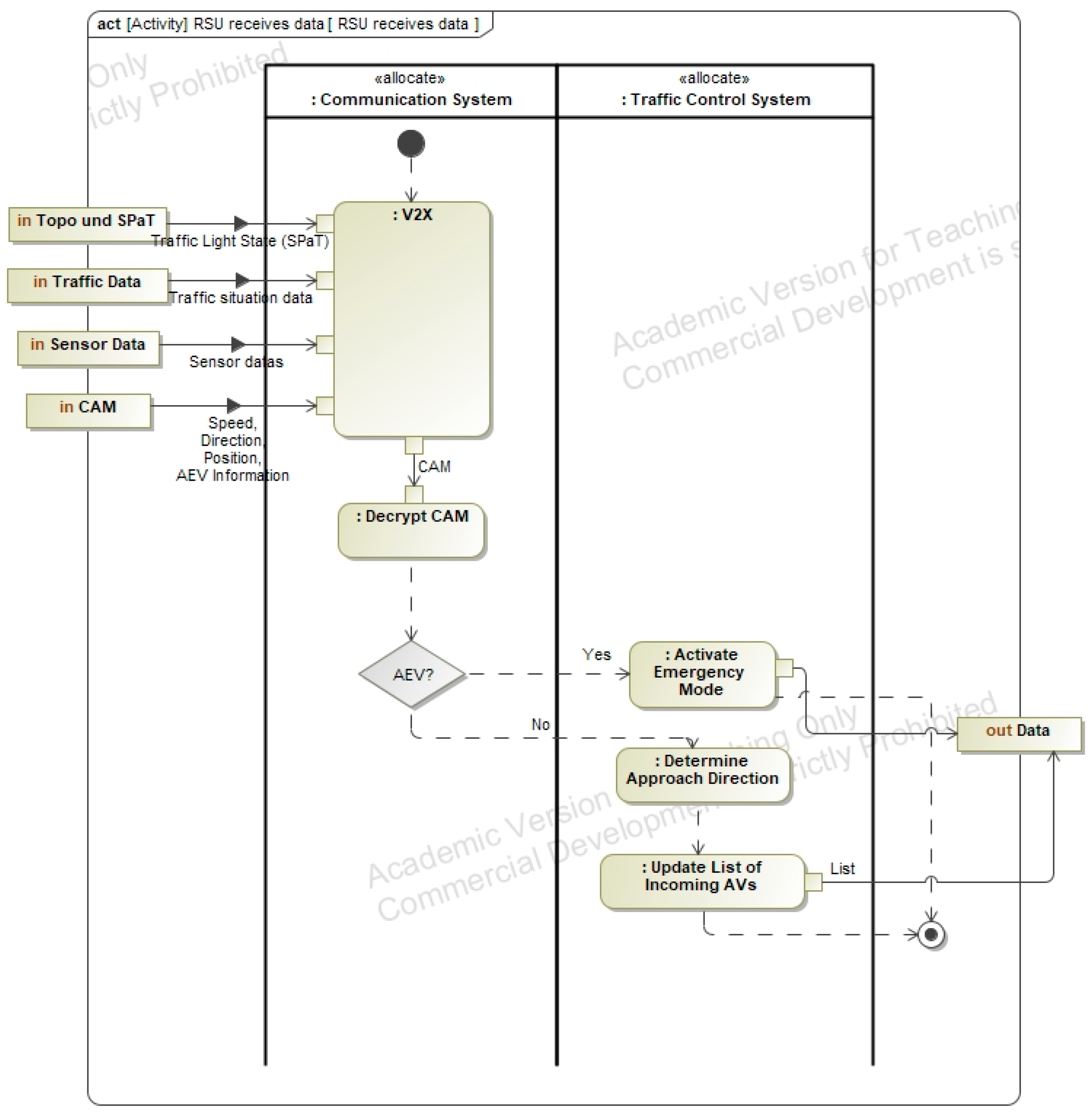
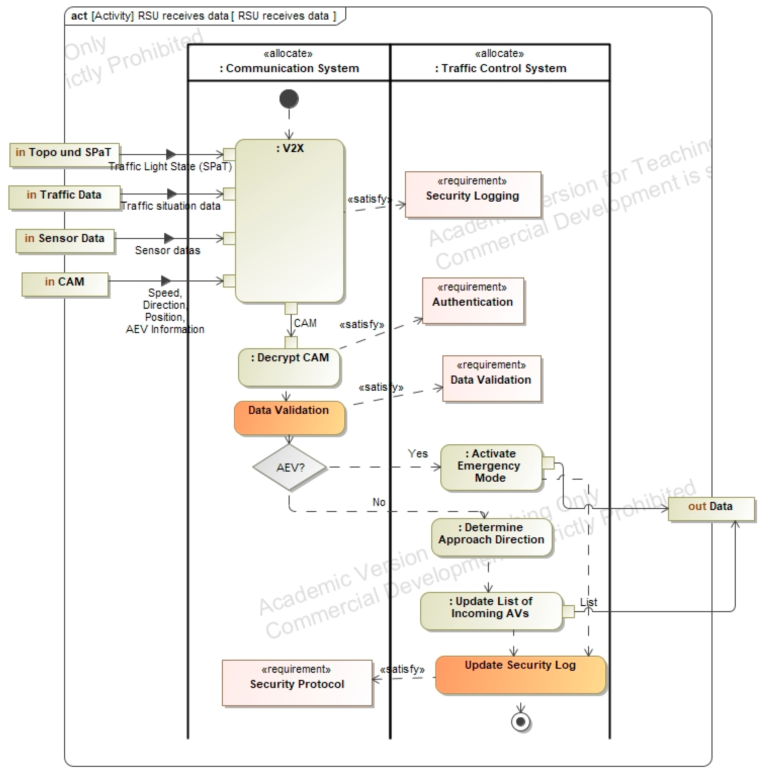
The next step in the system modeling process involves the definition of the functional architecture of the intelligent intersection. This layer describes the interaction of system components and the flow of control and information between them. Functions representing the behavior described in the use cases are modeled using activity diagrams. For example, Figure A6 illustrates the function “RSU receives data”, which forms part of the use case “AEV passes intersection”. This function handles data intake from autonomous vehicles, AEVs, traffic signals (TSS), sensors, and the traffic management center (TMC), forwarding it to the RSU’s control unit. Input and output flows are derived directly from the use case activity diagram. Additional modeled functions include “AEV passage calculation”, “TSS control”, and “return to normal operation”, as shown in Figure A6.

3.4.3. Logical Architecture

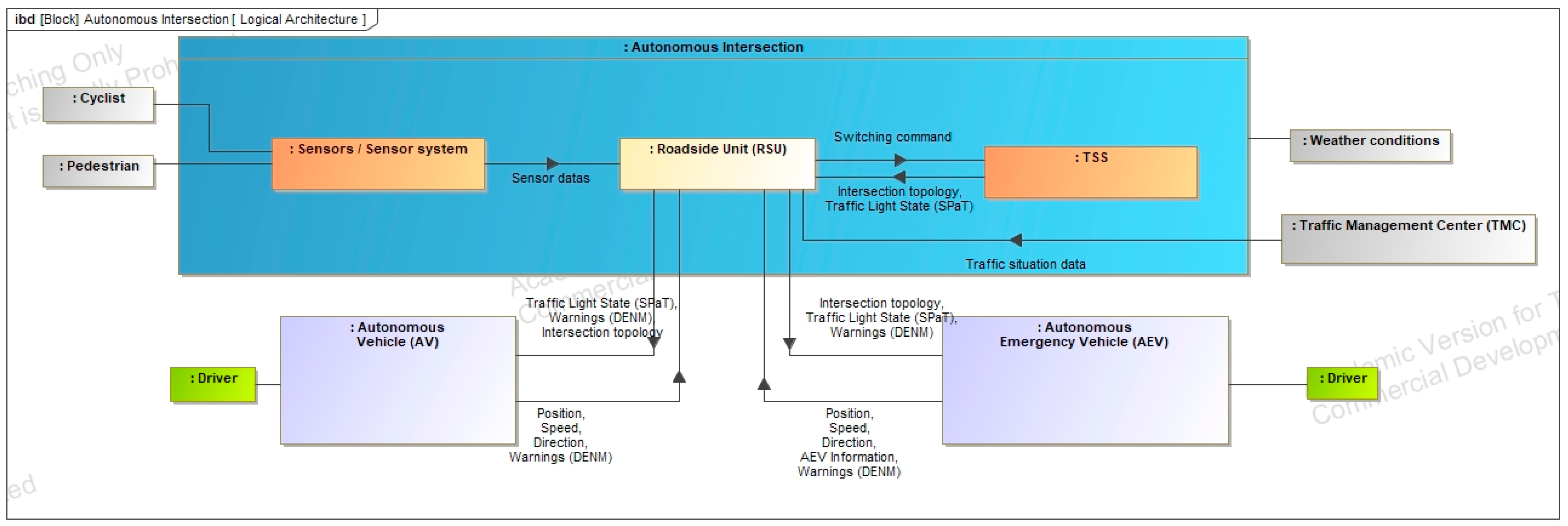
The logical architecture of the intelligent intersection builds upon the functional architecture and system context, enabling a detailed view of the system’s internal structure and component relationships. Represented using an internal block diagram, it extends the system context by decomposing the intersection into discrete components. The Roadside Unit (RSU) serves as the central element, managing communication, data exchange, and overall system control. Additional core components include the sensor system and the traffic signal controller (TSS), which monitor and regulate traffic flow, ensuring coordinated and efficient operation, as shown in Figure A7.

3.5. MBSE Modeling—Solution Level

The final level of the MBSE-Grid addresses the system components of the intelligent intersection. Based on the logical architecture, the component structure is first derived, followed by the modeling of component behavior and the definition of component requirements. This process is exemplified using the Roadside Unit (RSU), illustrating the decomposition of system functions into detailed, implementable elements.

3.5.1. Component Requirements

Based on the system requirements, structures, and behaviors, the final step involves modeling the component requirements. Key requirements include providing a reliable communication interface, interacting with sensors, controlling the traffic signal system, optimizing traffic flow, and detecting and responding to hazardous situations, as shown in Figure A8.

3.5.2. Component Behavior

Building on the component structure, the behavior of individual components is modeled. The behavior of the Roadside Unit (RSU) is represented using a sequence diagram, which illustrates the RSU’s tasks and its interactions with other system components. The diagram provides a clear view of how the communication system and control unit interact internally and externally within the intelligent intersection system, as shown in Figure A9.

3.5.3. Component Assembly

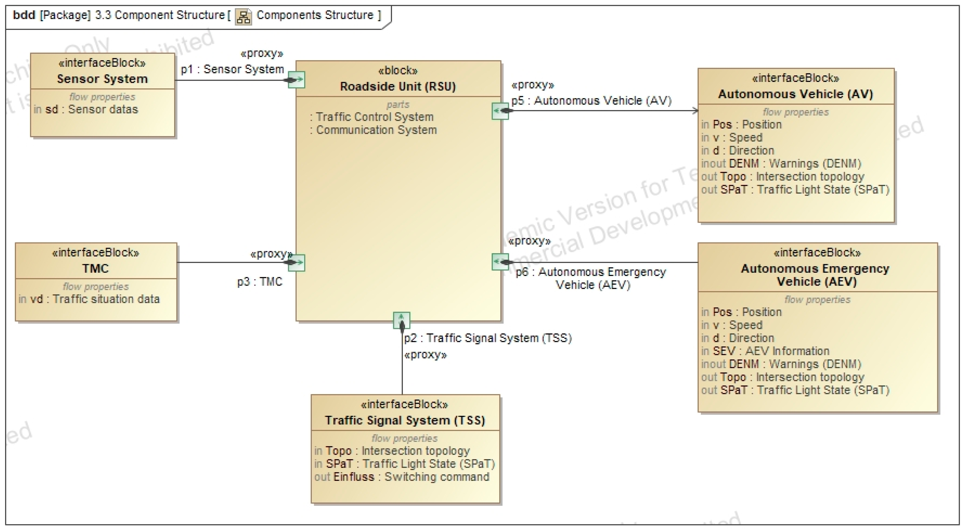
The architecture of individual components and their interactions are defined in this section. Central to the system is the Roadside Unit (RSU), which interfaces with sensors, the traffic management center (TMC), the traffic signal system (TSS), autonomous vehicles, and emergency vehicles. The RSU’s internal structure is further detailed using an internal block diagram comprising a communication system and a traffic control system. These subsystems exchange data internally, while the communication unit interfaces with all external components of the intersection, as shown in Figure A10 and Figure A11.

4. Method for Identifying Safety and Security Requirements

A systematic approach is required to identify safety and security requirements, which is best supported by model-based methods. Compared to traditional text-based approaches, model-based techniques offer improved consistency, traceability, and integration of safety and security data within system models. Using SysML, the Object Management Group (OMG) provides a standardized profile for modeling hazards, potential damages, and reliability analyses such as FTA (Failure Tree Analysis) and FMEA (Failure Mode and Effects Analysis), along with structured safety case argumentation [36]. Building on this foundation, Dassault Systèmes developed the Cameo Safety and Reliability Analyzer Plugin, enabling integrated safety and reliability analysis throughout the modeling process [37]. This plugin serves as the basis for the development and extension of the methodology used in this work.

4.1. Dassault Systemes Safety and Reliability Analysis

Ensuring reliability and safety is critical in complex systems across various domains. While reliability refers to a system’s ability to perform a required function under specified conditions over time, safety denotes the absence of unacceptable risks [38]. To model these aspects effectively, extended modeling tools are necessary. Model-Based Systems Engineering (MBSE), particularly through the MBSE-Grid and SysML, offers a structured framework for system modeling but lacks native constructs for integrating safety and reliability data. To address this gap, the Cameo Safety and Reliability Analyzer Plugin, based on OMG standards, extends SysML with dedicated constructs for modeling safety and reliability. It supports standards such as FMEA (IEC 60812:2006) [39], IEC 62304 [40], and ISO 14971:2007 [41], and integrates functional safety for road vehicles per ISO 26262 [37]. In this approach, the MBSE-Grid is extended with a Safety and Reliability View, representing a new column. Analysis results are captured as discrete elements (e.g., FMEA artifacts) prioritized by criticality. These inform new safety and reliability requirements, which are then integrated into the system architecture and behavior. All modifications must be reassessed to verify their impact on overall system safety and reliability.

4.2. Method for the General Implementation of Safety and Security Requirements

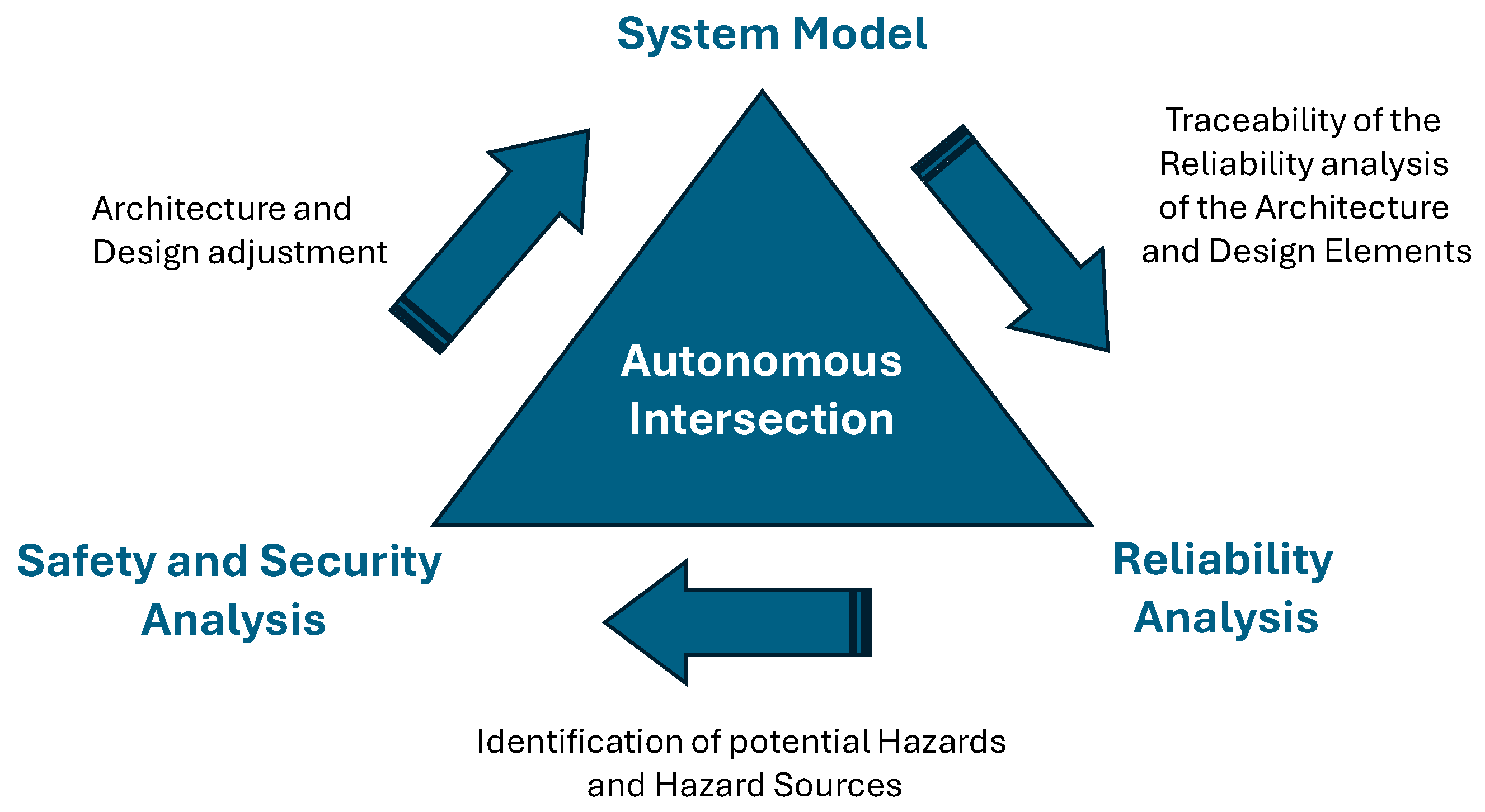
The previously introduced approach by Dassault Systèmes serves as the foundation for the integrated safety and security analysis. Building on this, a generalized method is developed to implement safety and security aspects within a system model—here, the intelligent intersection. The process begins with a reliability analysis, followed by hazard identification and a combined safety and security assessment. Based on the results, the system architecture and design are iteratively refined and re-evaluated until no critical vulnerabilities remain. This methodology extends the MBSE-Grid, as shown in Figure 3, by adding a dedicated Safety and Security View, aligned with the Dassault Systèmes Safety and Reliability Analysis approach [37].
The additional view is integrated into the grid to support systematic modeling of safety-related elements. To implement safety and security requirements within an existing system model, preliminary safety and security management is conducted, followed by a detailed system analysis, focusing on identifying all relevant safety, security, and reliability aspects, as well as the interactions between system components. Potential failure modes and their impacts are assessed using a System FMEA in accordance with IEC 60812:2006 [39], with the Risk Priority Number (RPN) guiding prioritization of mitigation measures. Given the role of autonomous vehicles, additional analysis is conducted based on ISO 26262 [13] and ISO 21434 [14], the Hazard Analysis and Risk Assessment (HARA) and the Threat Analysis and Risk Assessment (TARA).
Based on these analyses, the identification process for of a safety and security requirements is conducted. These requirements are then integrated into the system model and validated to ensure full compliance, forming the safety and security concept for the SoI. The methodology requires continuous and coordinated interaction between safety and security processes and must be regularly reviewed to maintain its effectiveness.

4.2.1. Initialization of the Method

The application of the methodology for identifying safety and security requirements begins with a structured system model organized according to the MBSE Grid. This grid-based modeling framework provides a systematic and traceable representation of the system across multiple abstraction levels and engineering perspectives. As outlined in Section 2, the system of interest (SoI) has been modeled with respect to stakeholder needs, use cases, system context, and functional and structural elements. This representation serves as the foundational reference and information basis for the method introduced in the following sections, as the focus of this study lies in the derivation and verification of Safety and Security (SaSe) requirements to ensure reliable and secure operation under various conditions. To achieve this, the initial analysis deliberately concentrates on the overall system level. Subsystem-specific details are intentionally excluded at this point to reduce complexity and enable a focused assessment of key architectural elements, their interactions, and associated vulnerabilities.
To support consistency throughout the iterative process, the system model must enable traceability between all relevant artifacts, such as requirements, structures, and behavioral views, across the MBSE Grid. This traceability is vital for linking identified safety and security concerns to their architectural origin and for validating refinements made during later stages of the development process.
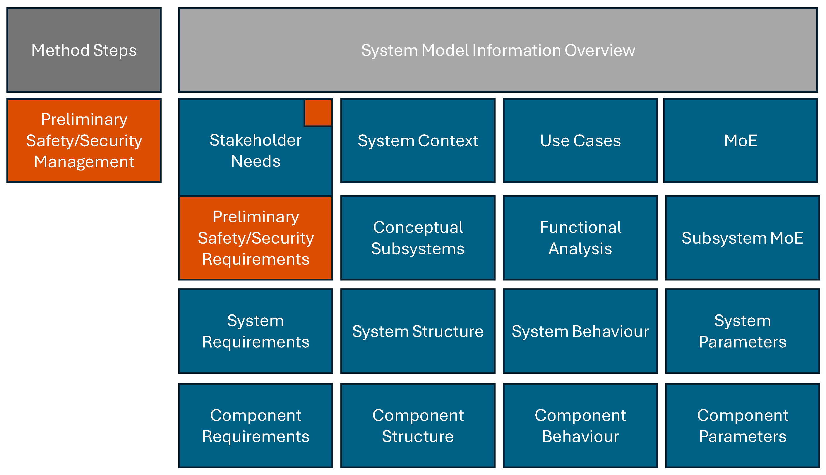
An overview of such a model configuration, serving as a basis for the methodological steps described in the following sections, is illustrated in Figure 4.

4.2.2. Preliminary Safety and Security Management

In accordance with the recommendations of Nolte et al. [19], it is of critical importance to perform proper preliminary management by embedding comprehensive compliance and normative objectives within the requirements framework from the outset. This ensures that regulatory and standardization goals are consistently addressed throughout the development process. The systematic visualization of the modeling approach, as illustrated in Figure 5, highlights the generation of new model artifacts, including both elements and diagrams. These artifacts are explicitly named and represented in the MBSE Grid using the designated color for the respective step. Furthermore, information from previously modeled stages that is reused in the current activity is indicated by small squares rendered in the color corresponding to the current step, thereby enhancing traceability and clarity of the modeling process, as shown in Figure 5.

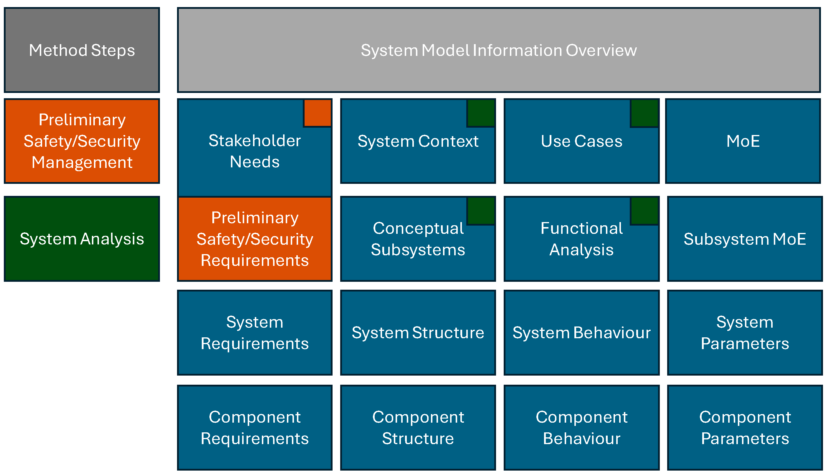
4.2.3. System Analysis

The analysis of the system, often referred to in the relevant safety and security standards ISO 26262 and ISO 21434 as the “ITEM Definition,” is based on the structure of the “Common ITEM Definition” as proposed by Nolte et al. [13,14,19]. In this context, existing information captured in the System Context, Use Cases, Conceptual Subsystems, and Functional Analysis diagrams is systematically reviewed and examined as a foundation for further safety and security assessments. Where necessary, additional normative information is incorporated to ensure compliance with standards and guidelines. This process is illustrated in Figure 6.

4.2.4. System FMEA

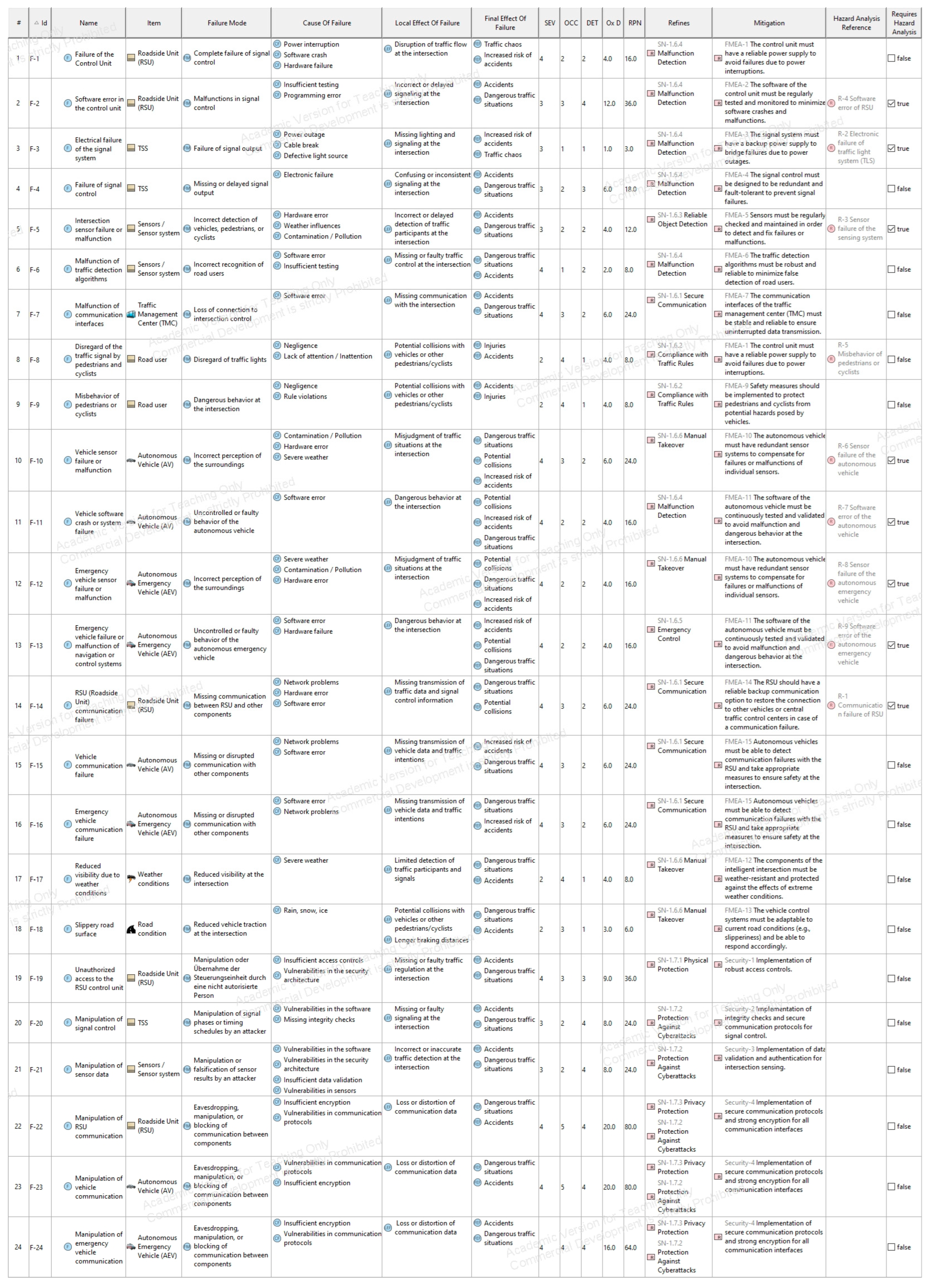
The System FMEA is a qualitative method for analyzing potential failure modes at the component and functional levels. In Cameo Systems Modeler, failure modes are first defined as FMEA items, which are then detailed and assessed in the FMEA table. Each row represents a failure scenario, with columns specifying the failure mode, cause, local and overall effects, and the Risk Priority Number (RPN) calculated from severity (SEV), occurrence (OCC), and detectability (DET). Relationships to stakeholder needs are shown in the Refines column, while Mitigation links identify elements that reduce failure risk.
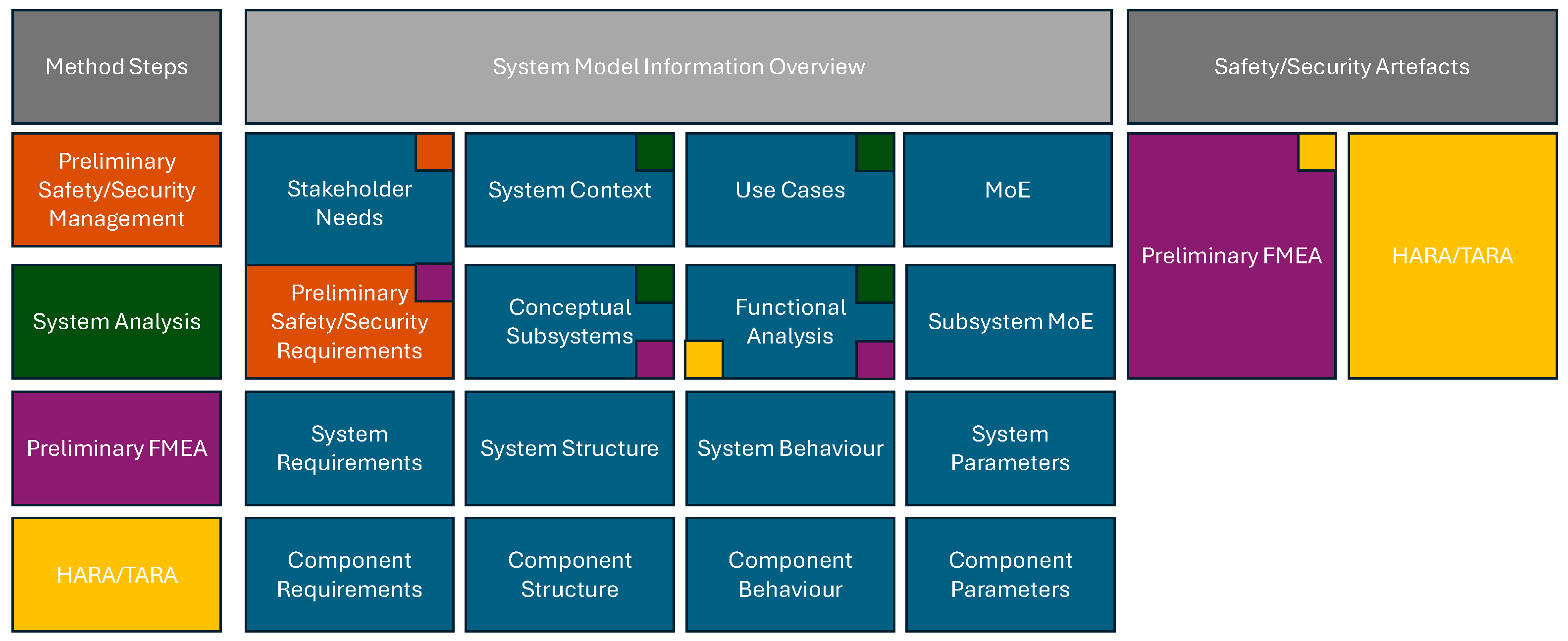
The System Safety and Security View within the extended MBSE-Grid is divided into safety and security segments. The safety analysis is further subdivided into system-level safety for the intersection and functional safety concerning autonomous vehicles. On the methodical level, the system FMEA is based on information provided in the model artifacts contained in the conceptual subsystems and functional analysis submodels and guided by the safety and security aims set out in the preliminary safety and security management. The artifacts and diagrams created in the System FMEA are located in the Preliminary FMEA field, as shown in Figure 7. The preliminary FMEA sets up the HARA (Hazard Analysis and Risk Assessment) and TARA (Threat Analysis and Risk Assessment) of the following steps, by identifying relevant scenarios in need of further safety or security relevant analysis.

4.2.5. HARA/TARA

As a continuation of the System FMEA, the methodology applies structured risk and threat assessment methods to address both safety and security aspects of the system. This is performed through HARA and TARA, which together form the analytical foundation for defining detailed safety and security requirements.
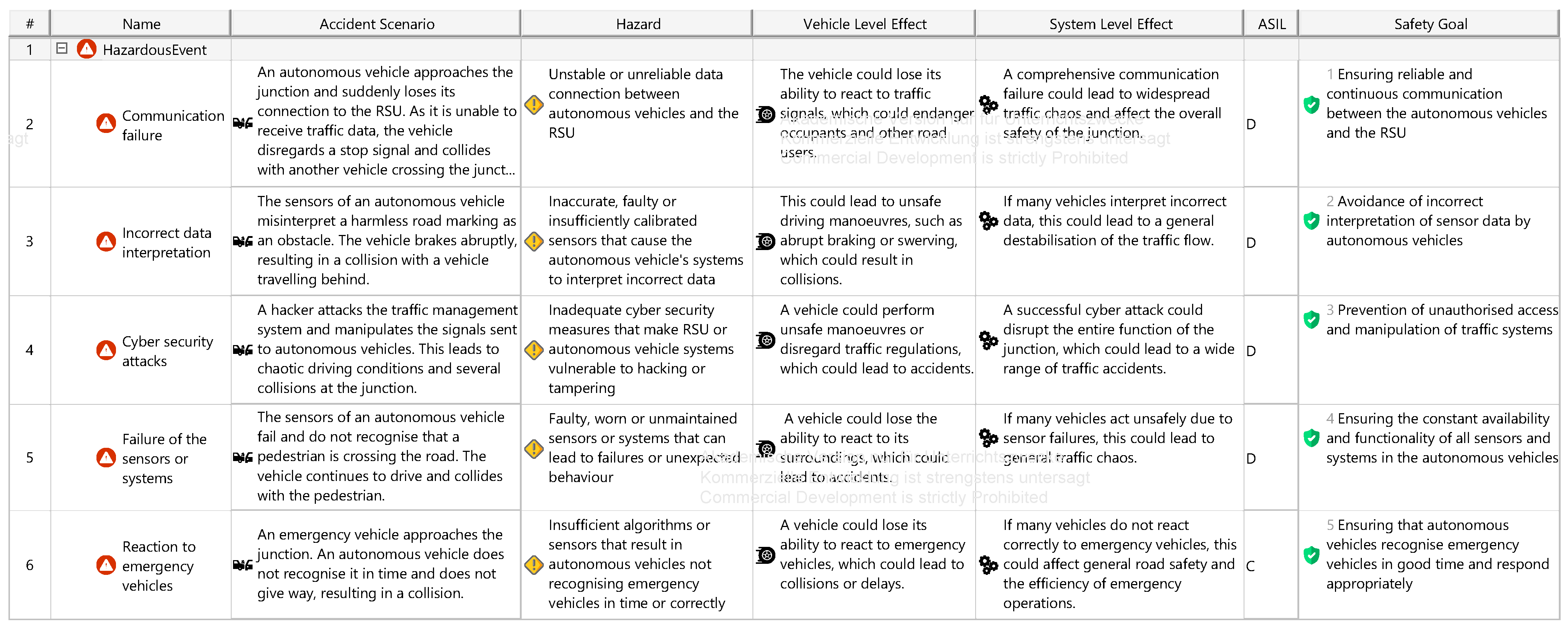
The HARA, as specified in ISO 26262 [13], is used to evaluate hazardous events by considering system architecture and operational behavior. Hazards are assessed in terms of severity, exposure, and controllability. Based on these parameters, Automotive Safety Integrity Levels (ASILs) are assigned, which guide the derivation of safety goals and corresponding requirements at functional, technical, hardware, and software levels.
In parallel, the TARA, as outlined in ISO/SAE 21434 [14], focuses on identifying and evaluating intentional threats. It involves the analysis of assets, potential attack vectors, and their impacts. Even when performed outside the modeling tool (e.g., due to tool limitations), TARA outcomes are linked back to the system model to maintain traceability. Both HARA and TARA build upon the results of the System FMEA and are guided by the preliminary safety and security objectives defined earlier. They help prioritize critical system scenarios requiring mitigation and provide a structured transition toward the definition of the final safety and security concept.
The integration of these analyses within the MBSE Grid is shown in Figure 8, which highlights how HARA and TARA relate to previously developed model artifacts and prepare the system for concept-level synthesis.

4.2.6. Safety/Security Concept

Following the risk and threat assessments conducted through HARA and TARA, the final step of the methodology focuses on consolidating and integrating the identified safety and security requirements into a system-wide concept. This concept addresses both system-level and component-level concerns and ensures that critical risks are mitigated by design. The safety and security concept is based on the results of all prior steps, particularly the risk prioritization from the System FMEA and the classification of hazards and threats in the HARA and TARA. The concept includes defined safety and security goals, functional and technical requirements, and, where applicable, mechanisms for ASIL decomposition and security level assignments.
Within the modeling framework, these elements are structured and allocated to relevant components, ensuring consistency with the architecture and behavioral models. Dependency matrices, traceability links, and SysML relationships (e.g., «satisfy», «refine») are used to maintain alignment between the conceptual safety/security layers and the system model.
The integration of this final methodological step into the MBSE Grid is illustrated in Figure 9, where the safety and security concept is positioned as the concluding output of the iterative analysis process.

5. Application of the Method to the Autonomous Intersection System

This section demonstrates the application of the previously introduced methodology (Section 3) using the system model of an autonomous intersection. Based on the model developed in Section 2, each step of the method is executed to identify, assess, and integrate safety and security requirements. The goal is to illustrate how the methodological framework can be effectively applied to a cyber–physical system within the domain of cooperative, automated mobility. Diagrams and modeling artifacts referenced throughout this section are included in Appendix A.4.

5.1. Modeling Scope and Context

The basis for this case study is the system model of an intelligent intersection for autonomous vehicles, as introduced in Section 2. The model has been structured using the MBSE Grid and includes key modeling elements such as stakeholder needs, system context, use cases, system requirements, and initial functional and structural architectures. The corresponding model artifacts are provided in Appendix A.1.
For the purpose of applying the safety and security methodology, the scope of analysis is defined at the system level. The focus is placed on the system of interest (intersection itself) and its critical components, including the RSU, sensor systems, and TSS. Subsystem-level refinements and peripheral elements are excluded at this stage to maintain analytical clarity and ensure a manageable level of detail.
This defined scope supports a targeted assessment of the system’s key interactions and vulnerabilities with respect to safety and security objectives. It also enables the traceable integration of method-specific artifacts into the existing model structure, following the abstraction levels and perspectives defined by the MBSE Grid. The application of the methodology begins with the integration of preliminary safety and security requirements, as outlined in the following subsection.

5.2. Integration of Preliminary Safety and Security Requirements

In accordance with the methodological framework outlined in Section 4.2.2, the first step in applying the safety and security analysis to the autonomous intersection model involves the integration of preliminary safety, security, and reliability objectives into the existing system model. These preliminary requirements reflect high-level normative expectations derived from relevant standards, such as ISO 26262 for functional safety and ISO/SAE 21434 for cybersecurity. Their purpose is to ensure that safety- and security-related aspects are considered from the beginning and systematically embedded into the model-based development process.
In the case of the autonomous intersection, a set of dedicated modeling elements was created and added to the MBSE Grid. These include generalized safety and security goals, such as ensuring safe communication with autonomous vehicles, maintaining system availability, or protecting traffic data integrity, which form the initial foundation for further analysis. A detailed overview of the preliminary safety, security, and reliability requirements modeled for the system of interest is provided in Appendix A.4, Figure A12. These requirements also define the responsibilities of key stakeholders and support the alignment of the development process with applicable regulatory and organizational goals.

5.3. System Analysis

In this step, the autonomous intersection system is analyzed at the system level to identify elements relevant to safety and security risks, following the methodological structure outlined in Section 4.2.3. The analysis is based on existing model artifacts which were created in the earlier modeling phase and are documented in Appendix A.1.
These artifacts are reviewed with a specific focus on their relevance for safety and security assessments. Where necessary, additional normative information may be integrated. However, for the present application example, no modifications to the existing diagrams or model artifacts have been required at this stage of the analysis.

5.4. System FMEA

Following the method described in Section 4.2.4, a System FMEA was conducted for the autonomous intersection system to assess potential failure scenarios related to key components and functions. The analysis focuses on elements such as the RSU, the TSS, sensors, and their interactions with autonomous and emergency vehicles. The failure modes were modeled in Cameo Systems Modeler using dedicated FMEA tables. Each failure scenario includes a defined cause, local and overall effects, and a calculated RPN based on severity, occurrence, and detectability. Mitigation links were established where applicable, and relationships to stakeholder needs were maintained through Refines connections. The analysis is embedded within the Safety and Security View of the MBSE Grid and divided into a system-level safety perspective for the infrastructure and a functional safety perspective for vehicle-related interactions. The results are documented in Appendix A.4, Figure A13. This step also forms the basis for the subsequent HARA and TARA analyses by identifying high-risk scenarios requiring further evaluation.

5.5. HARA/TARA

Based on the FMEA results, a detailed HARA and TARA were conducted for the autonomous intersection system. Safety-critical components and functions were analyzed by evaluating system architecture and operational behavior. The analysis identified key hazards, such as communication loss between the RSU and signal controller (R-1) or sensor failures affecting pedestrian detection (R-3), and rated them as high-risk. These scenarios were assessed in Cameo using severity, occurrence, and detectability values to calculate their RPN. Risk mitigation strategies, including redundant communication paths, fault detection algorithms, and sensor calibration, were then modeled and implemented. These measures reduced the overall risk and led to reclassification of several items to lower RPN levels. The results of this safety analysis are documented in Appendix A.4, Figure A14 and Figure A15.
In the context of cybersecurity, the TARA method was applied to identify threats such as unauthorized access or data manipulation. Since Cameo Systems does not natively support security analysis, the TARA was performed externally. Nevertheless, the results were integrated into the system model and linked to the relevant architectural elements. Each subsystem was assessed for possible attack scenarios, which then informed the definition of security goals and technical requirements across all abstraction layers. The resulting security requirements are reflected in Appendix A.4, Table A1.
The overall HARA and TARA activities were informed by the system’s functional analysis and guided by the safety and security goals defined in the preliminary step. Their combined results lay the groundwork for the final synthesis of a comprehensive safety and security concept in the next phase of the methodology.

5.6. Safety/Security Concept

Based on the preceding FMEA, HARA, and TARA analyses, a comprehensive safety and security concept was developed and integrated into the model of the autonomous intersection. This concept aggregates critical requirements on both system and component levels and addresses safety-related hazards as well as cybersecurity threats.
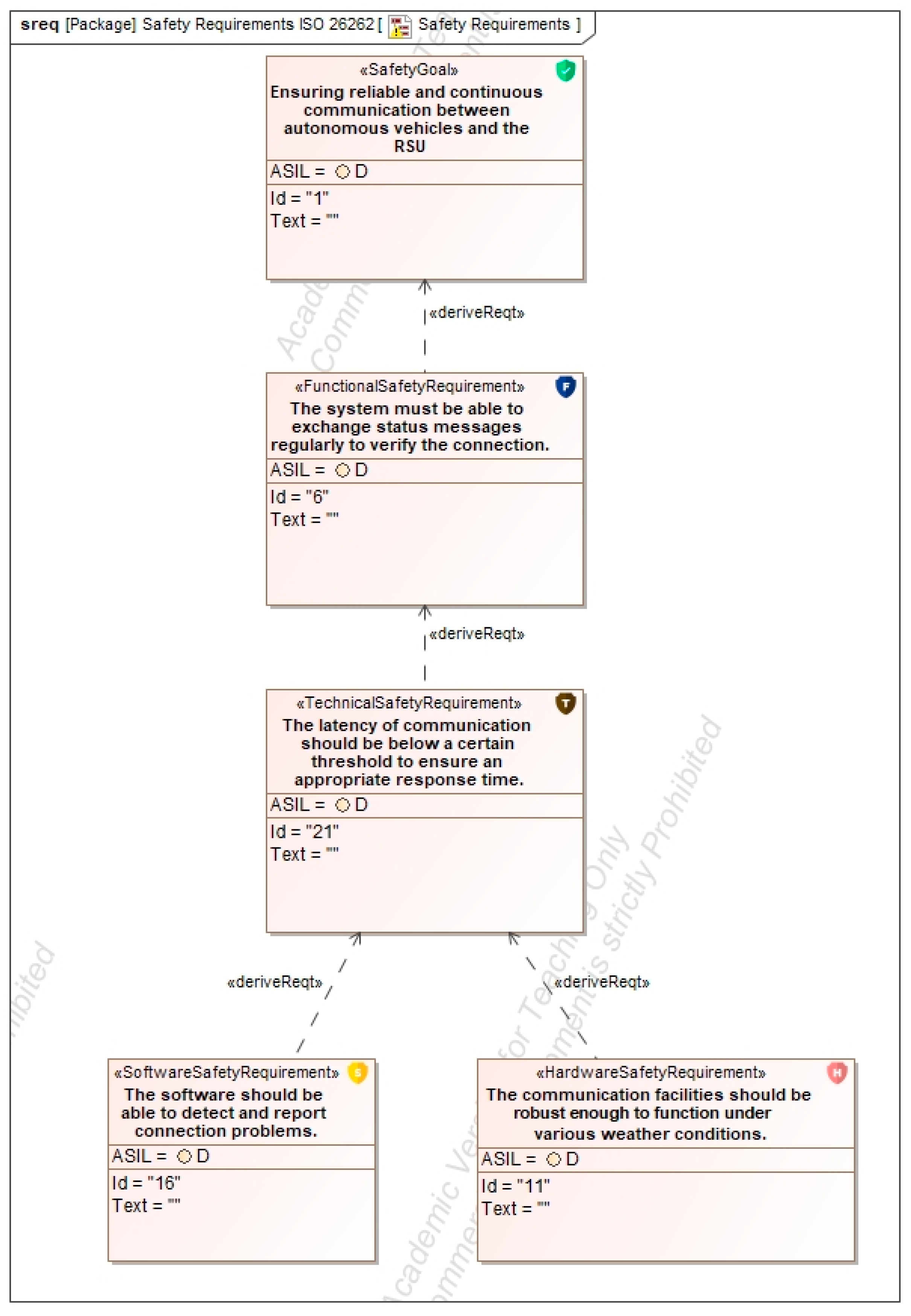
For safety, requirements are derived and structured according to ISO 26262. These include ASIL-classified goals, with decomposition applied where appropriate to distribute safety responsibilities across functions and technical domains. An example of ASIL decomposition is illustrated in Appendix A.4, Figure A16. The resulting specifications encompass functional, technical, hardware, and software requirements relevant to intersection control, vehicle communication, and environmental monitoring.
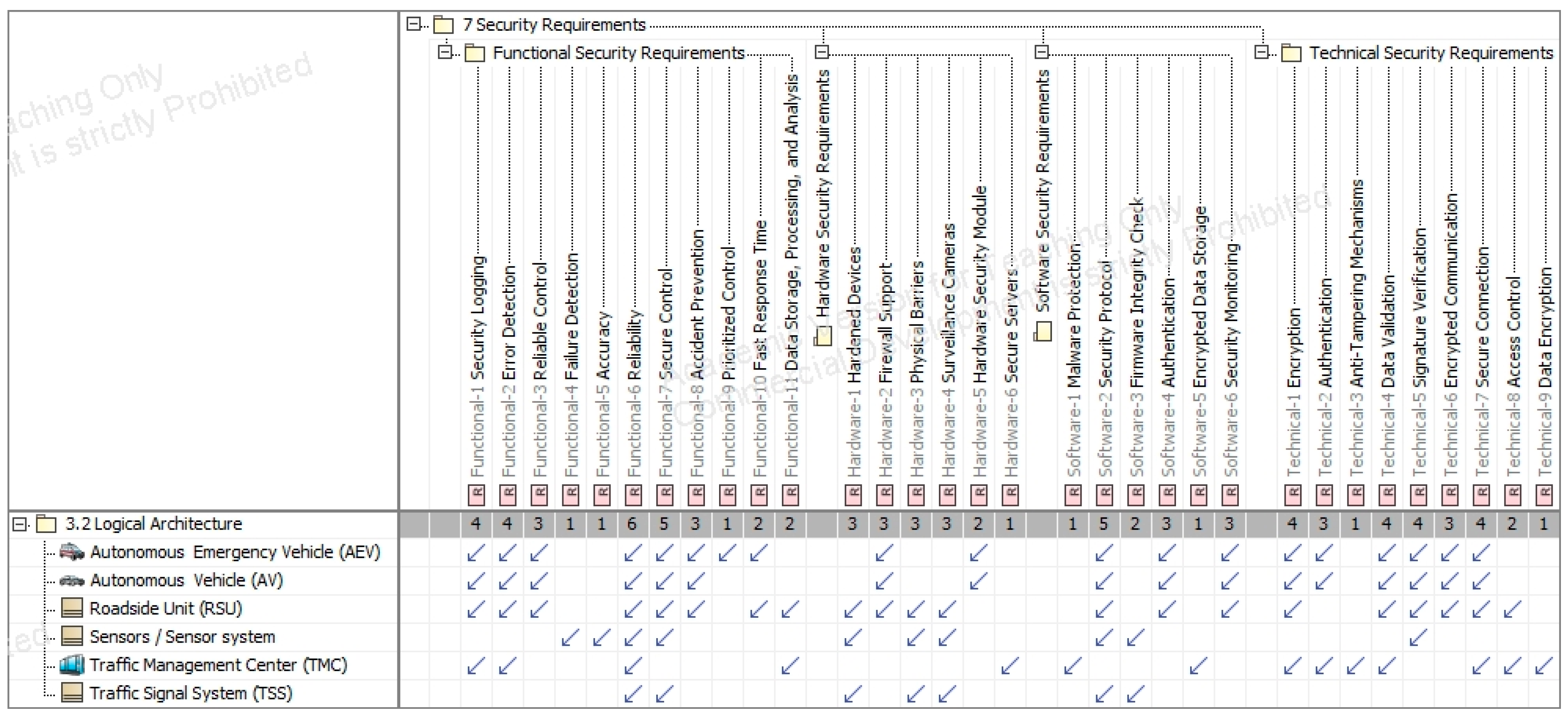
On the security side, the concept reflects the goals and requirements identified through TARA. These are embedded into the model as linked elements and cover measures such as access protection, data encryption, system integrity, and fallback strategies. Security-augmented activity diagrams and structural views are included to ensure consistent integration across system layers, as shown in Appendix A.4, Figure A17, Figure A18 and Figure A19.
Altogether, the safety and security concept ensures that risks are adequately mitigated within the operational context of the intelligent intersection. Its implementation in the system model provides a traceable foundation for subsequent verification and validation activities.

6. Discussion

Building on Dassault Systèmes’ Safety and Reliability Analysis, the method provides a comprehensive and structured approach for integrating safety and security requirements into system models. Its iterative nature enables continuous identification and mitigation of vulnerabilities, while the extension of the MBSE-Grid to include a dedicated Safety and Security View facilitates a holistic modeling approach. The methodology begins with a System FMEA, enabling detailed identification of failure modes and causes. Its integration into Cameo Systems enhances traceability and visual clarity. However, the FMEA’s effectiveness depends heavily on analyst expertise, and its qualitative focus may require supplementary quantitative methods for complete risk assessment. Subsequent system- and component-level analyses for both safety and security ensure comprehensive coverage aligned with standards such as [13], incorporating risk tables, hazard assessments, and derived requirements. While this dual focus is a strength, the process may be resource-intensive and complex for smaller projects. Additionally, reliance on external tools like TARA, not natively supported in Cameo, may introduce integration challenges. The use of dependency matrices supports structured implementation, yet managing complex relationships between requirements and functions may hinder clarity and maintainability. Despite these limitations, the methodology demonstrates strong alignment with best practices, emphasizing integration, traceability, and completeness. Future improvements should aim for greater efficiency and seamless tool integration. Overall, the approach represents a significant contribution to model-based Safety and Security analysis, particularly in the domain of autonomous systems, and offers a robust foundation for further research and development.
The development of cyber–physical systems of systems (CPSoSs) presents significant challenges for safety and security analysis, primarily due to the high complexity introduced by numerous interacting functions, components, and communication pathways. To address this, the proposed method offers a specialized template designed to support engineers and scientists in structuring their analyses. This template can be directly applied or adapted to specific project needs, providing a systematic framework that facilitates coordinated safety and security assessments. By leveraging this pre-defined structure, analysts are guided through key steps, reducing the likelihood of oversight and improving both the efficiency and consistency of the analysis process.

7. Conclusions

This paper presents a comprehensive system model of an intelligent intersection and introduces an integrated methodology for identifying and implementing safety and security requirements. The foundation was established through theoretical insights into MBSE using SysML, along with an overview of safety and security engineering principles. The MBSE-Grid approach was adapted for modeling the intersection system and extended to include Safety and Security Views, enabling a holistic representation of functional, structural, and risk-related system aspects. The methodology builds upon Dassault Systèmes’ Safety and Reliability Analysis and guides the iterative integration of safety and security elements within system models. It incorporates FMEA, HARA, and TARA, and emphasizes the traceability and prioritization of risk mitigation measures. The process was demonstrated using the intelligent intersection model, focusing particularly on emergency scenarios involving autonomous emergency vehicles (AEVs). A generalized use case was developed to handle both longitudinal and cross-traffic situations effectively, ensuring flexibility without the need for case-specific adaptations. The implementation follows a structured process beginning with system-level analysis, extending through functional safety [13] and threat assessment [14], and culminating in the integration and validation of requirements across all MBSE levels. Dependency matrices, activity diagrams, and satisfy relationships ensure that requirements are consistently linked to the model’s structure and behavior. Although the methodology offers clarity, structure, and extensibility, it also presents challenges in complexity, time requirements, and tool interoperability—particularly regarding security analysis, which is not natively supported in Cameo Systems. Therefore, future work should prioritize balancing analytical depth with efficiency and improving the seamless integration of external tools. In conclusion, the developed methodology contributes significantly to the model-based safety and security analysis of autonomous systems. Its adaptability and comprehensive approach provide a robust foundation for further research and practical applications in the domain of intelligent transportation and autonomous mobility.

8. Outlook

The methodology developed in this work offers substantial potential for future research. Subsequent studies could focus on refining the approach, applying it to other domains within autonomous driving, or integrating emerging technologies and standards. In particular, evaluating and enhancing the methodology across different contexts and applications presents a promising research direction. Further exploration of compatibility with other analysis tools and the assessment of efficiency in large-scale, real-world implementations would also be valuable. Overall, this work provides a meaningful contribution to the ongoing discourse on optimizing safety and security in system models.

Author Contributions

Conceptualization, U.V.K. and J.E.; methodology, U.V.K., A.S. and J.E.; modeling, J.E. and A.S.; validation, A.S. and T.V.; formal analysis, U.V.K.; investigation, J.E.; writing—original draft preparation, A.S.; writing—review and editing, U.V.K. and A.S.; visualization, J.E.; supervision, T.V.; project administration, U.V.K.; funding acquisition, T.V. All authors have read and agreed to the published version of the manuscript.

Funding

The publication of this paper has been funded by the TU Braunschweig Publication Fund.

Institutional Review Board Statement

Not applicable.

Informed Consent Statement

Not applicable.

Data Availability Statement

The original contributions presented in this study are included in the article. Further inquiries can be directed to the corresponding author.

Acknowledgments

This work was conducted in the context of the project “ZL MOB” (Zukunftslabor Mobilität), which was funded by the “Zukunft. Niedersachsen” initiative of the Lower Saxon Ministry for Science and Culture and the Volkswagen Foundation.

Conflicts of Interest

The authors declare no conflicts of interest.

Abbreviations

The following abbreviations are used in this manuscript:
ASILAutomotive Safety Integrity Level
AEVAutonomous Emergency Vehicle
AVAutonomous Vehicle
CPSCyber Physical System
DETDetectability
FMEAFailure Mode and Effects Analysis
FTAFailure Tree Analysis
HARAHazard analysis and Risk Assessment
HazopHazard and Operapility Study
IECInternational Electrotechnical Comission
INCOSEInternational Council on Systems Engineering
ISOInternational Organisation for Standardisation
LIDARLight Detection and Ranging
LSA(TSS)Traffic Signal System
MBSEModel Based Systems Engineering
MoEMeasures of Effectiveness
OCCOccurrence
OMGObject Management Group
RPNRisk Priority Number
RSURoadside Unit
SESystems Engineering
SEVSeverity
STRIDESpoofing, Tampering, Repudiation, Information Disclosure,
Denial of Service, Elevation of Privilege
SysMLSystem Modeling Language
TARAThreat Analysis and Risk Assessment
TMCTraffic Management Center
V2XVehicle to X
VDIVerein Deutscher Ingenieure

Appendix A

Appendix A.1. Problem (Black Box) Diagrams
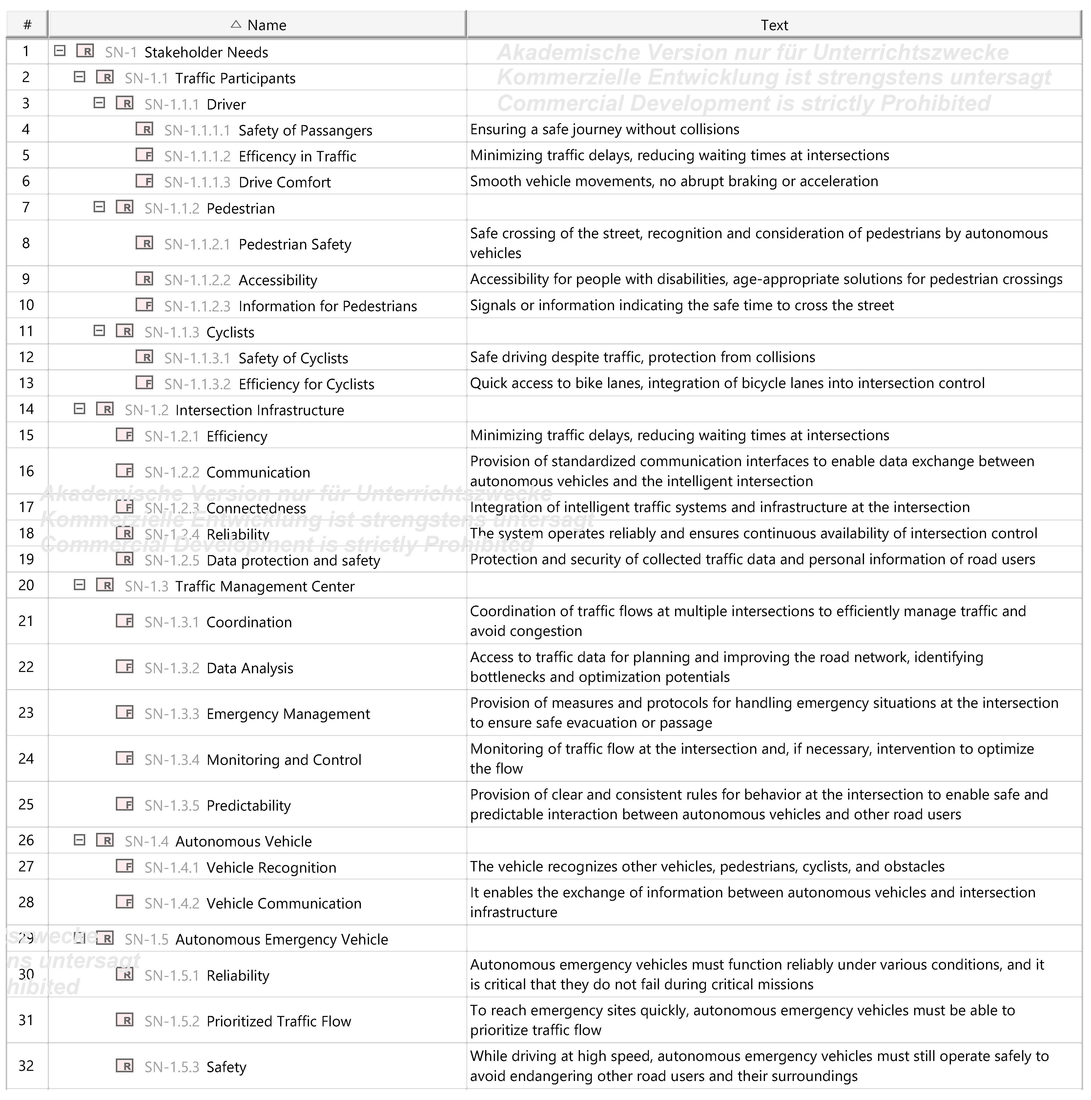
Figure A1. Stakeholder Needs.
Asi 08 00168 g0a1
Figure A2. Use Case Diagram.
Asi 08 00168 g0a2
Figure A3. Activity Diagram for the Use Case “AV passes Intersection”.
Asi 08 00168 g0a3
Figure A4. System Context.
Asi 08 00168 g0a4

Appendix A.2. Problem (White Box) Diagrams
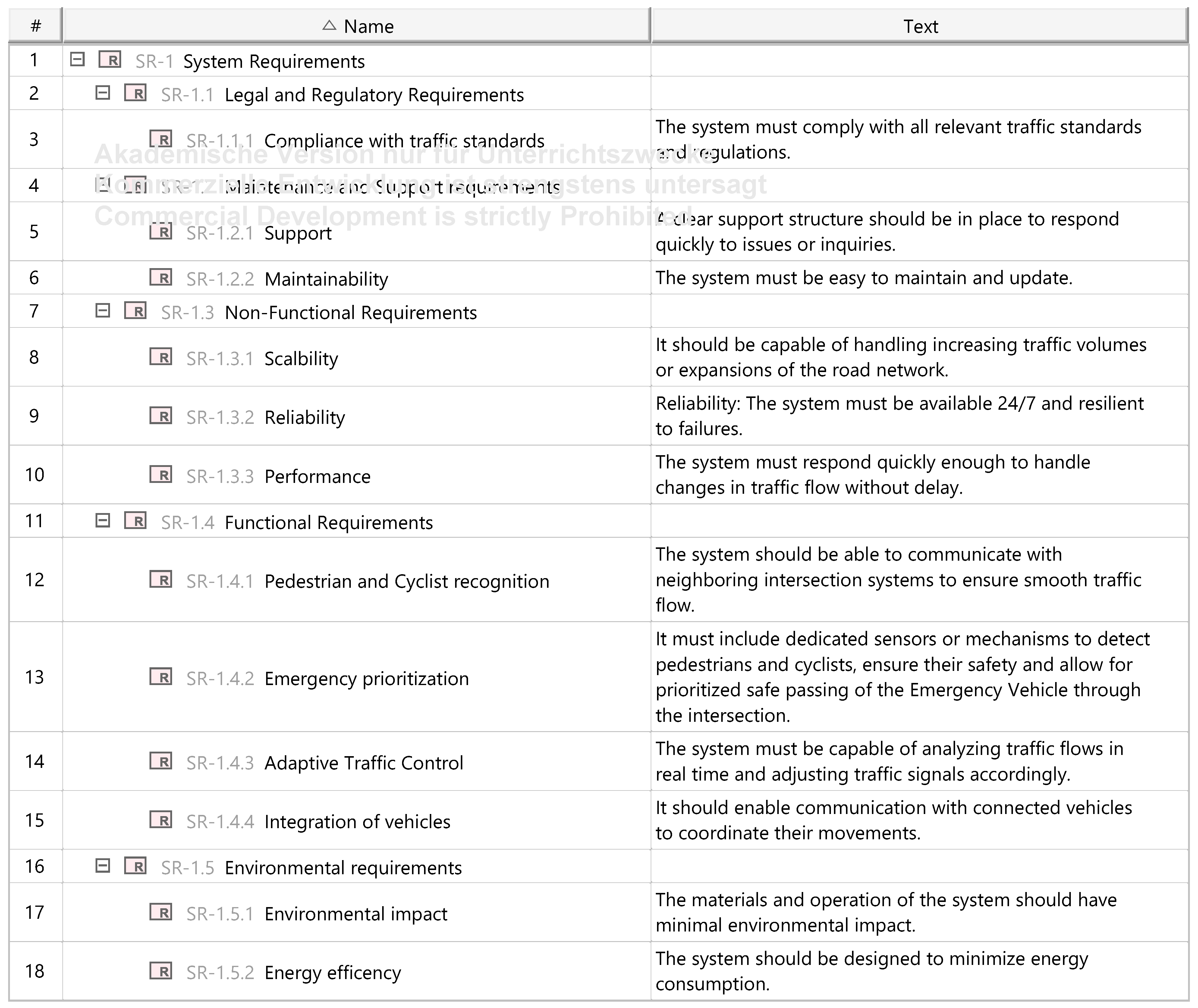
Figure A5. System Requirements.
Asi 08 00168 g0a5
Figure A6. Functional Analysis (RSU receives data).
Asi 08 00168 g0a6
Figure A7. Logical Architecture.
Asi 08 00168 g0a7

Appendix A.3. Solution Diagrams

Figure A8. Component Requirements (RSU).
Asi 08 00168 g0a8
Figure A9. Component Behavior.
Asi 08 00168 g0a9
Figure A10. Component structure.
Asi 08 00168 g0a10
Figure A11. Component structure RSU (Internal).
Asi 08 00168 g0a11

Appendix A.4. Method Implementation
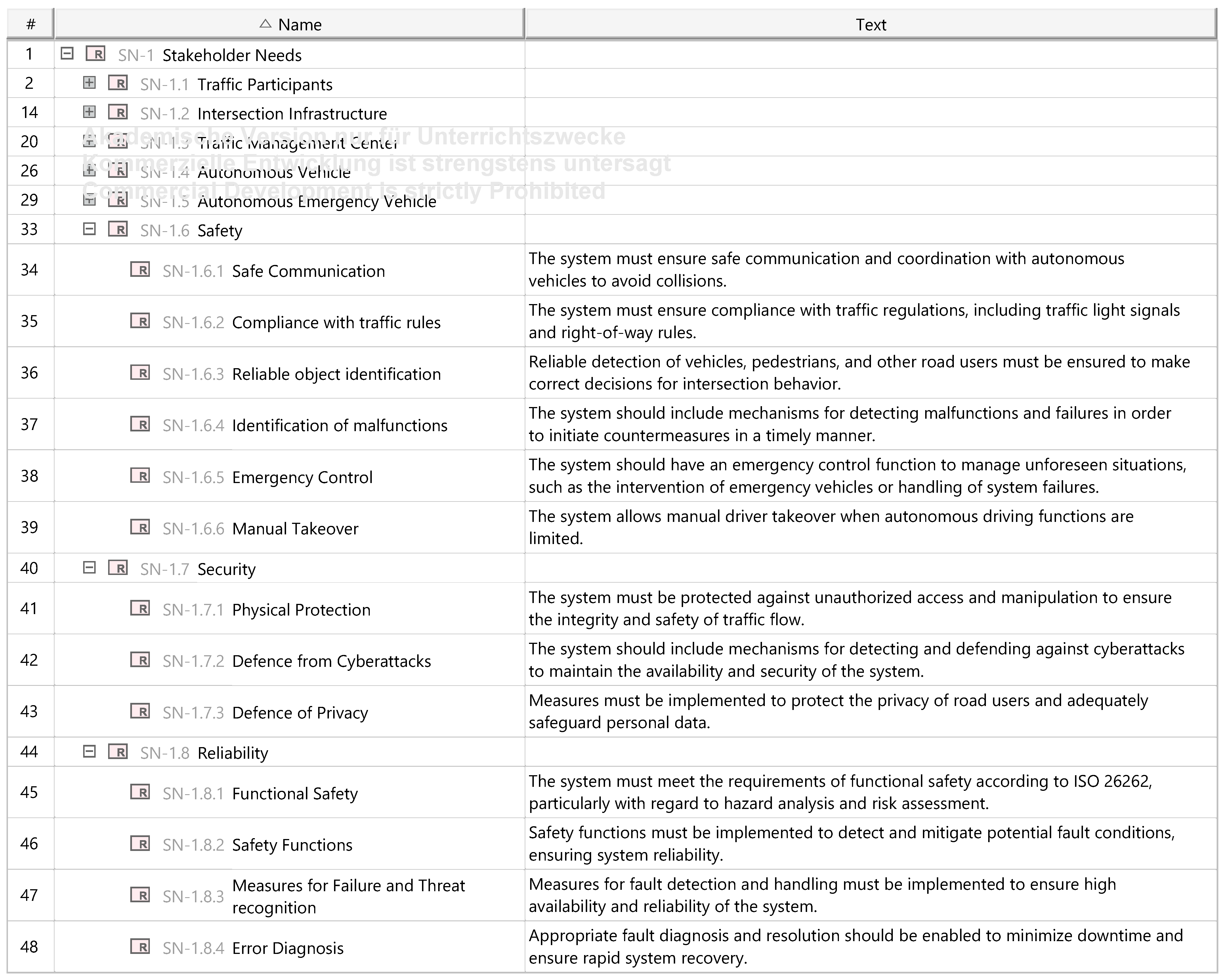
Figure A12. Extended Stakeholder Needs.
Asi 08 00168 g0a12
Figure A13. System FMEA.
Asi 08 00168 g0a13
Figure A14. System Hazard Analysis.
Asi 08 00168 g0a14
Figure A15. HARA based on ISO 26262.
Asi 08 00168 g0a15
Table A1. TARA Table.
IDLocationAssetsThreatsAttacksThreat LevelImpact LevelSecurity LevelSecurity Goal
1RSUDataHacker attackMalware, Hacking, Physical attackHighHighMediumIntegrity, Confidentiality
2TSSControlSabotagePhysical attackMediumHighMediumAvailability
3SensorsInformationManipulationMalware, HackingHighMediumLowIntegrity
4AVVehicle controlUnauthorized controlHackingHighHighMediumSafety, Integrity
5AEVControlUnauthorized controlHackingHighHighMediumSafety, Integrity
6TMCTraffic dataData theftMalware, HackingMediumMediumHighConfidentiality
7Pedestrians/CyclistsSafetyAccidents due to system failureTechnical failureHighHighLowSafety
Figure A16. Safety Requirements derivation.
Asi 08 00168 g0a16
Figure A17. Relation Matrix between Design- and Security-Requirements.
Asi 08 00168 g0a17
Figure A18. Safety and Security augmented activity diagram of the AEV.
Asi 08 00168 g0a18
Figure A19. Safety- and Security-augmented activity diagram of the RSU.
Asi 08 00168 g0a19

References

  1. Gausemeier, J.; Czaja, A.; Wiederkehr, O.; Dumitrescu, R.; Tschirner, C.; Steffen, D. Studie: Systems Engineering in der industriellen Praxis. In Tag des Systems Engineering; Maurer, M., Schulze, S.-O., Eds.; Carl Hanser Verlag GmbH & Co. KG: München, Germany, 2013; pp. 113–122. ISBN 978-3-446-43915-3. [Google Scholar]
  2. Alt, O. Modellbasierte Systementwicklung mit SysML; Carl Hanser Verlag GmbH & Co. KG: München, Germany, 2012; ISBN 978-3-446-43066-2. [Google Scholar]
  3. VDI/VDE 2206:2021-11; Development of Mechatronic and Cyber-Physical Systems. Verein Deutscher Ingenieure (VDI): Düsseldorf, Germany, 2021.
  4. Windolph, A. Das V-Modell im Projektmanagement: Definition, Typen und Phasen. Available online: https://projekte-leicht-gemacht.de/blog/projektmanagement/klassisch/v-modell/ (accessed on 8 April 2025).
  5. INCOSE. Systems Engineering Vision 2020; INCOSE: San Diego, CA, USA, 2007. [Google Scholar]
  6. Hick, H.; Bajzek, M.; Faustmann, C. Definition of a system model for model-based development. SN Appl. Sci. 2019, 1, 1074. [Google Scholar] [CrossRef]
  7. Two Pillars GmbH. What Is MBSE? Available online: https://www.two-pillars.de/was-ist-mbse/ (accessed on 8 April 2025).
  8. Huth, T.; Vietor, T. Systems Engineering in der Produktentwicklung: Verständnis, Theorie und Praxis aus ingenieurswissenschaftlicher Sicht. Gr. Interakt. Org. 2020, 51, 125–130. [Google Scholar] [CrossRef]
  9. Friedenthal, S.; Moore, A.; Steiner, R. A practical Guide to SysML: The Systems Modeling Language, 3rd ed.; Elsevier: Amsterdam, The Netherlands; Morgan Kaufmann: Waltham, MA, USA, 2015; ISBN 0128008008. [Google Scholar]
  10. Morkevicius, A.; Aleksandraviciene, A.; Mazeika, D.; Bisikirskiene, L.; Strolia, Z. MBSE Grid: A Simplified SysML-Based Approach for Modeling Complex Systems. INCOSE Int. Symp. 2017, 27, 136–150. [Google Scholar] [CrossRef]
  11. Yaacoub, J.-P.A.; Salman, O.; Noura, H.N.; Kaaniche, N.; Chehab, A.; Malli, M. Cyber-physical systems security: Limitations, issues and future trends. Microprocess. Microsyst. 2020, 77, 103201. [Google Scholar] [CrossRef]
  12. Macher, G.; Schmittner, C.; Veledar, O.; Brenner, E. ISO/SAE DIS 21434 Automotive Cybersecurity Standard—In a Nutshell. In Proceedings of the International Conference on Computer Safety, Reliability, and Security. SAFECOMP 2020 Workshops, Lisbon, Portugal, 15 September 2020; Casimiro, A., Ortmeier, F., Schoitsch, E., Bitsch, F., Ferreira, P., Eds.; Springer International Publishing: Cham, Switzerland, 2020; pp. 123–135, ISBN 978-3-030-55582-5. [Google Scholar]
  13. ISO 26262:2018; Road Vehicles—Functional Safety. International Standards Organization: Geneva, Switzerland, 2018.
  14. ISO 21434:2021; Road Vehicles—Cybersecurity Engineering. International Standards Organization: Geneva, Switzerland, 2021.
  15. Tacchini, M. What is Functional Safety. In Functional Safety of Machinery; Tacchini, M., Ed.; Wiley: Hoboken, NJ, USA, 2023; pp. 47–86. ISBN 9781119789048. [Google Scholar]
  16. Lundgren, B.; Möller, N. Defining Information Security. Sci. Eng. Ethics 2019, 25, 419–441. [Google Scholar] [CrossRef]
  17. Kriso, S.; Klarmann, J.; Loderhose, C.; Wiemer, F.; Gebauer, C.; Burton, S.; Ihle, M. Safety Oder Security: Sicher Unterwegs in Einer Manipulierten Umwelt. Available online: https://www.embedded-software-engineering.de/safety-oder-security-sicher-unterwegs-in-einer-manipulierten-umwelt-a-813822/ (accessed on 8 April 2025).
  18. Furrer, F.J. Safety and Security of Cyber-Physical Systems; Springer Fachmedien Wiesbaden: Wiesbaden, Germany, 2022; ISBN 978-3-658-37181-4. [Google Scholar]
  19. Nolte, B.; Stein, A.; Vietor, T. Designing a Method for Identifying Functional Safety and Cybersecurity Requirements Utilizing Model-Based Systems Engineering. Appl. Syst. Innov. 2025, 8, 45. [Google Scholar] [CrossRef]
  20. Ebert, C.; Brasse, M.; Metzker, E. Safety and security requirements engineering. In Proceedings of the 16th Internationales Stuttgarter Symposium, Stuttgart, Germany, 15–16 March 2016; Bargende, M., Reuss, H.-C., Wiedemann, J., Eds.; Springer Fachmedien Wiesbaden: Wiesbaden, Germany, 2016; pp. 1171–1182, ISBN 978-3-658-13254-5. [Google Scholar]
  21. Tietjen, T.; Decker, A. FMEA-Praxis: Einstieg in die Risikoabschätzung von Produkten, Prozessen und Systemen, 4th ed.; Carl Hanser Verlag GmbH & Co. KG: München, Germany, 2020; ISBN 9783446462113. [Google Scholar]
  22. Edler, F.; Soden, M.; Hankammer, R. Fehlerbaumanalyse in Theorie und Praxis; Springer: Berlin/Heidelberg, Germany, 2015; ISBN 978-3-662-48165-3. [Google Scholar]
  23. International Electrotechnical Commission; International Electrotechnical Commission Technical Committee 56. Hazard and Operability Studies (HAZOP Studies): Application Guide/International Electrotechnical Commission = Études de Danger et d’Exploitatbilité (Études HAZOP): Guide d’Application/Commission Electrotechnique Internationale, 2nd ed.; International Electrotechnical Commission: Geneva, Switzerland, 2016; ISBN 9782832232088. [Google Scholar]
  24. Okamura, H.; Dohi, T. SRATS: Software reliability assessment tool on spreadsheet (Experience report). In Proceedings of the 2013 IEEE 24th International Symposium on Software Reliability Engineering (ISSRE 2013), Pasadena, CA, USA, 4–7 November 2013; pp. 100–107. [Google Scholar]
  25. Microsoft. Threat Modeling. Available online: https://www.microsoft.com/en-us/securityengineering/sdl/threatmodeling (accessed on 8 April 2025).
  26. Verein Deutscher Ingenieure. Automotive Security 2019; Verein Deutscher Ingenieure (VDI): Düsseldorf, Germany, 2019; ISBN 9783181023587. [Google Scholar]
  27. Wuthishuwong, C.; Traechtler, A.; Bruns, T. Safe trajectory planning for autonomous intersection management by using vehicle to infrastructure communication. J. Wirel. Com. Netw. 2015, 2015, 33. [Google Scholar] [CrossRef]
  28. Wang, C.; Ma, X.; Jia, L.; Lai, Z.; Yang, Z.; Yan, H.; Zhao, J. CPS Architecture Design for Urban Roadway Intersections Based on MBSE. J. Int. Con. Veh. 2024, 7, 190–204. [Google Scholar] [CrossRef]
  29. Japs, S.; Anacker, H.; Dumitrescu, R. SAVE: Security & safety by model-based systems engineering on the example of automotive industry. Procedia CIRP 2021, 100, 187–192. [Google Scholar] [CrossRef]
  30. Mažeika, D.; Butleris, R. MBSEsec: Model-Based Systems Engineering Method for Creating Secure Systems. Appl. Sci. 2020, 10, 2574. [Google Scholar] [CrossRef]
  31. Mažeika, D.; Butleris, R. Integrating Security Requirements Engineering into MBSE: Profile and Guidelines. Secur. Commun. Netw. 2020, 2020, 5137625. [Google Scholar] [CrossRef]
  32. PiąTek, P.; Mydłowski, P.; Buczacki, A.; Moskwa, S. Concept of Using the MBSE Approach to Integrate Security Patterns in Safety-Related Projects for the Automotive Industry. IEEE Trans. Intell. Transport. Syst. 2024, 25, 15477–15492. [Google Scholar] [CrossRef]
  33. Lee, W.-H.; Chiu, C.-Y. Design and Implementation of a Smart Traffic Signal Control System for Smart City Applications. Sensors 2020, 20, 508. [Google Scholar] [CrossRef] [PubMed]
  34. Lorkowski, S.; Kannenberg, O.; Kesting, A.; Witte, N. UR:BAN—Vernetztes Verkehrssystem: Forschungsprojekt: Schlussbericht zu den Teilprojekten: VV—Vernetztes Verkehrssystem: Laufzeit: 01.01.2012-31.12.2015. Available online: https://www.tib.eu/de/suchen/id/TIBKAT%3A870099108/UR-BAN-Vernetztes-Verkehrssystem-Forschungsprojekt (accessed on 8 April 2025).
  35. Gath, N.; Kaths, J.; Kürschner, M.; Schendzielorz, T.; Krause, J.; Schön, T.; Noll, B.; Mosebach, H.; Petry, F.; Ungureanu, T.; et al. Leitfaden für die Einrichtung Kooperativer Systeme auf Öffentlicher Seite. Available online: https://www.mos.ed.tum.de/vt/forschung/projekte/abgeschlossene-projekte/urban-abgeschlossen-2016/urban-leitfaden/ (accessed on 8 April 2025).
  36. J2735_202007; V2X Communications Message Set Dictionary. SAE International: Warrendale, PA, USA, 2020.
  37. Morkevičius, A.; Aleksandravičienė, A. MagicGrid® Book of Knowledge; Dassault Systèmes: Waltham, MA, USA, 2021. [Google Scholar]
  38. Biggs, G.; Post, K.; Armonas, A.; Yakymets, N.; Juknevicius, T.; Berres, A. OMG standard for integrating safety and reliability analysis into MBSE: Concepts and applications. INCOSE Int. Symp. 2019, 29, 159–173. [Google Scholar] [CrossRef]
  39. International Electrotechnical Commission. Analysis Techniques for System Reliability: Procedure for Failure Mode and Effects Analysis (FMEA), 2nd ed.; Prepared by IEC Technical Committee 56, Dependability; International Electrotechnical Commission: Geneva, Switzerland, 2006; ISBN 283188425X. [Google Scholar]
  40. IEC 62304:2006(en); Medical Device Software—Software Life Cycle Processes. International Standards Organization: Geneva, Switzerland, 2006.
  41. ISO 14971:2019; Medical Devices—Application of Risk Management to Medical Devices. International Standards Organization: Geneva, Switzerland, 2019.
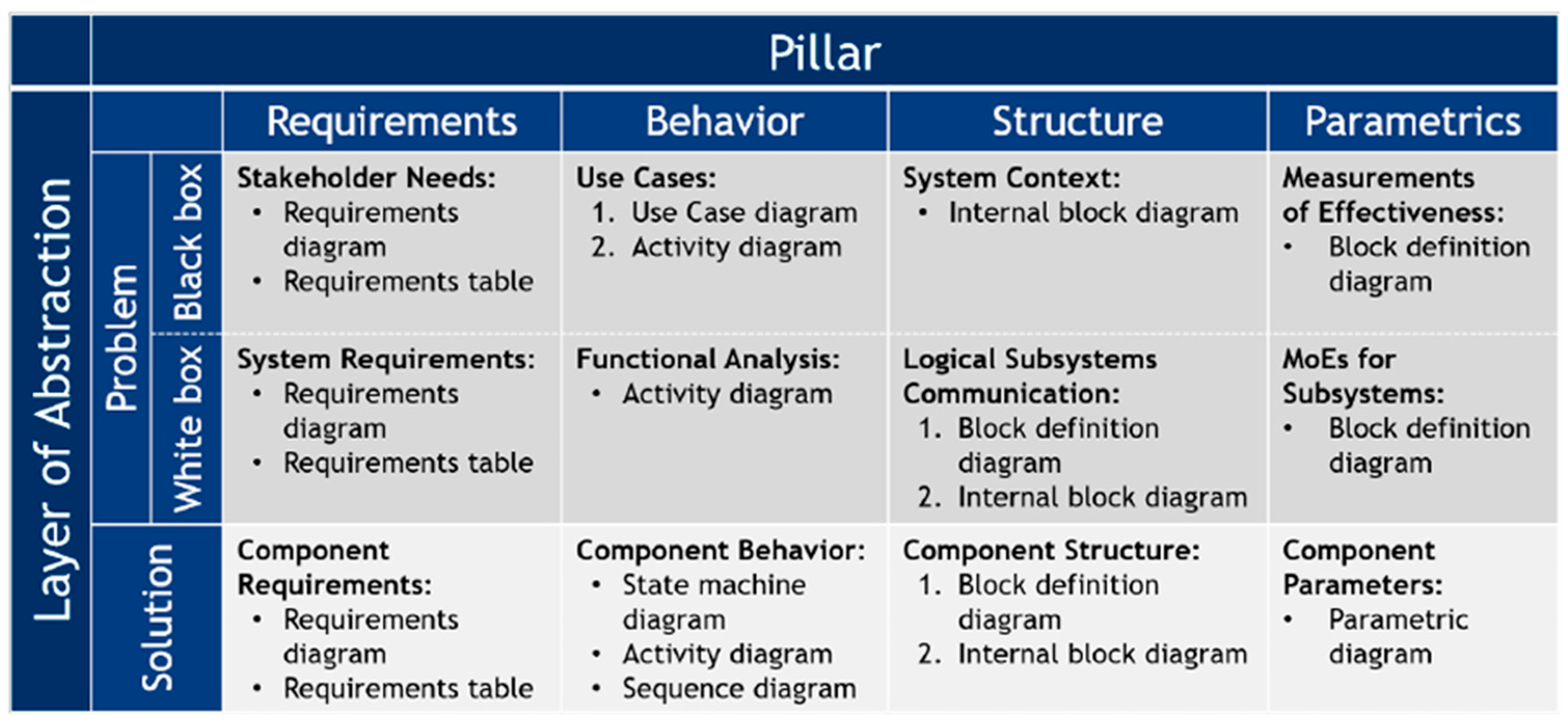
Figure 1. MBSE-Grid approach [10].
Asi 08 00168 g001
Figure 2. Schematic Diagram of the intersection.
Asi 08 00168 g002
Figure 3. Implementation of the Safety and Security Analysis [37].
Asi 08 00168 g003
Figure 4. Available model information at the beginning of method application, based on the MagicGrid method [10].
Asi 08 00168 g004
Figure 5. Adjusted MBSE Grid, showcasing the integration of the preliminary safety and security requirements definition.
Asi 08 00168 g005
Figure 6. Adjusted MBSE Grid, showcasing the integration of the System Analysis step.
Asi 08 00168 g006
Figure 7. Adjusted MBSE Grid, showcasing the integration of the Preliminary FMEA step.
Asi 08 00168 g007
Figure 8. Adjusted MBSE Grid, showcasing the integration of the HARA and TARA steps.
Asi 08 00168 g008
Figure 9. Adjusted MBSE Grid, showcasing the integration of the Safety and Security Concepts.
Asi 08 00168 g009
Table 1. Information management of the method.
PublicationSourceIntersectionMBSESafetySecurityRequirements
Engineering
Autonomous
Mobilty
Additional
Analytical Methods
(e.g., FMEA)
Normative Basis
Nolte et al.[19]-+++++-+
Wuthishuwong et al.[27]+-+--+--
Wang et al.[28]+++-+++-
Japs et al.[29]-+++++-+
Mažeika & Butleris (2020a)[30]-++++---
Mažeika & Butleris (2020b)[31]-+-++--+
Piątek et al.[32]-++++--+
Disclaimer/Publisher’s Note: The statements, opinions and data contained in all publications are solely those of the individual author(s) and contributor(s) and not of MDPI and/or the editor(s). MDPI and/or the editor(s) disclaim responsibility for any injury to people or property resulting from any ideas, methods, instructions or products referred to in the content.