Abstract
Closed-section composite structures with corners present significant challenges during forming and molding for achieving the desired thickness distribution over the profile. The experimental investigation in the present work was designed to compare laminates constructed entirely from twill-weave carbon fabric prepregs with different hybrid laminates constructed by combining unidirectional (UD) carbon fiber prepregs around the flat and twill-weave fabric prepregs around the curved section. Although the UD fiber prepregs were found to be more compressible than the twill-weave prepregs, the desired thickness distribution (to within 2% of design geometry), along with the proper level of consolidation, was obtained only with the hybrid construction that had an equal number of UD plies around the flat and twill-weave plies around the curved section. In contrast, the thickness distribution obtained with the all-twill prepreg laminate deviated from the design geometry by 5.4%. Forming simulations incorporating experimentally derived compaction behavior of different plies were used to predict the local compaction, tool–ply contact pressures, and thickness profile of the molded part. The simulation results for thickness profiles showed similar trends to those observed in experiments.
1. Introduction
Lightweight composite structures for biomedical applications have been fabricated with a range of reinforcements and prepregs, using compression molding [1,2,3,4]. The thickness distribution in the walls of the part is easier to control in open-profile geometries such as C-, U-, and V-shaped sections with free edges during forming [5,6,7,8]. In contrast, closed geometries, such as D-shaped or circular cross-sections, lack free edges; this limits lateral compliance during forming and may lead to wrinkling as the preform shears and densifies under pressure. Furthermore, consolidation of prepregs in closed and angled geometries is known to result in non-uniform compaction conditions and corresponding variations in wall thickness [9,10]. The D-shaped beam discussed in this paper is part of a load-bearing support for facilitating the installation of implants.
Prepregs commonly used in forming are based on either unidirectional (UD) or woven reinforcements, each providing distinct in-plane and through-thickness responses [11]. UD prepregs offer high stiffness and strength along the fiber direction, whereas woven fabrics provide superior conformability and interlaminar toughness [12,13]. Increasingly, hybrid or mixed-architecture laminates incorporating both UD and woven layers are being used to balance stiffness, drapeability, and consolidation behavior [14,15,16]. Recently published numerical models capture the consolidation-induced fiber reorientation within prepreg plies, arising from transverse squeeze flow of the polymer matrix [17,18]. This also contributes to non-uniform thickness distribution in the molded parts.
Effective laminate design for forming must account not only for drapeability but also for the thickness evolution associated with consolidation. These objectives can be achieved more readily with open cross-sections by optimizing the layer stacking sequence and by selecting reinforcements with appropriate mechanical characteristics. The use of genetic algorithms for optimization of the layup sequence is well established [19,20]. Almeida et al. [21] and Park et al. [22] have shown that optimizing the stacking sequence of UD plies leads to higher stiffness and load-carrying capacity, reduced deflection, and improved stability under both linear and nonlinear loading conditions. Such optimized layups also improved failure resistance by minimizing local stress concentrations. Albazzan et al. [23] showed that mixing different material types within a laminate (e.g., carbon and glass UD plies) enabled more efficient stiffness distribution through optimization of lamination parameters. The hybrid laminates referred to in the current paper were obtained by combining prepregs with different architectures from the same components. Hochard [24] demonstrated that woven carbon-fiber-reinforced laminates exhibit higher delamination resistance than UD plies, while UD laminates provide higher stiffness but fail through transverse cracking and delamination. High-modulus UD fibers greatly increase stiffness and buckling resistance while displaying a lower degree of compaction.
Forming and molding of hybrid laminates into closed geometries introduces additional complexities associated with the distinct consolidation behavior and shear compliance of the constituent layers [25,26,27,28,29]. UD plies exhibit low shear flexibility and are more susceptible to wrinkling and local thickness variations, while woven prepreg layers shear more readily but may remain resin-rich if not compacted sufficiently [30,31]. Furthermore, closed geometries inherently produce non-uniform tool–ply contact pressures, often over-compacting curved regions while leaving flatter areas under-consolidated [32]. These pressure gradients can lead to heterogeneous consolidation, resin-rich or resin-lean zones, and significant thickness inconsistencies, all of which affect part quality and dimensional fidelity [33]. In particular, Hubert et al. [32] demonstrated that internal corners experience a pressure deficit, while external corners exhibit a pressure intensification, and that this pressure imbalance produces the characteristic corner thickening or thinning observed in cured parts. Another device that has been demonstrated for handling corner effects is incorporating compliant layers, such as variable-thickness rubber inserts [34,35]. Complementing this, Maes et al. [33] showed through in situ measurements that these pressure gradients evolve during the low-viscosity consolidation window and actively drive material flow into or away from the corner, establishing the final thickness profile. Hence, managing the pressure distribution within the consolidated part is essential for achieving uniform thickness in closed geometries.
The objectives of the present paper were to characterize several laminate designs in the forming and molding of a D-shaped part with experimental molding runs, and to model simulations with detailed experimental inputs. The forming simulations were used to compute the evolving pressure and thickness distributions, followed by evaluation of residual stresses and distortion after molding. D-shaped parts were fabricated using a heated aluminum compression mold with integrated cooling. The measured wall thickness distributions agreed closely with the simulation results, thus allowing for the comparison of pressure distributions achieved in the molded part with various laminate designs.
2. Materials and Methods
2.1. Materials
The laminates in this study were prepared from two epoxy-based carbon fiber prepregs: a 2 × 2 twill-weave prepreg with a fiber volume fraction of 45%, offering improved drapeability; and a UD prepreg with a higher fiber volume fraction of 54%, providing greater stiffness along the fiber axis. Forming was conducted using tools machined from 2618 aluminum–copper alloy, selected for its high strength, thermal conductivity, and stability at elevated temperatures.
2.2. Design and Fabrication
A D-shaped hollow component was selected as the representative geometry. The profile features a combination of curved and flat regions, including corners between these segments. This configuration offers a comprehensive representation of the various deformation modes encountered during the forming process. The final part has a thickness of 3.56 mm, an outer diameter of 34.9 mm, and an overall length of 635 mm. The schematic of the part is shown in Figure 1.

Figure 1.
D-shaped composite part: (a) cross-section and (b) isometric view of full geometry.
The forming tool was a three-part machined mold assembly, comprising a central arbor and two mold halves (top and bottom), each machined from a single block of aluminum alloy billet to ensure dimensional precision and thermal uniformity. The arbor replicated the internal profile of the part and had a length of 700 mm. Both the top and bottom mold halves were designed with internal cavities to accommodate four 356 mm (14 in.) cartridge heaters, enabling controlled and uniform heating during the forming and curing processes. Additionally, an integrated cooling system was implemented by drilling axial and crossflow channels within the mold halves, allowing water to circulate as a coolant and facilitate rapid thermal cycling. This configuration ensured effective temperature control throughout the process. The mold schematic is shown in Figure 2.
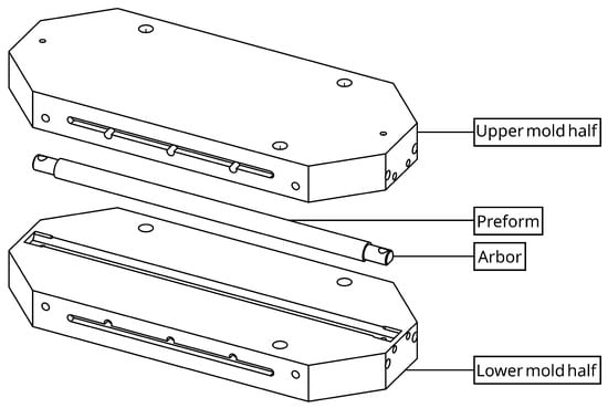
Figure 2.
Exploded view of mold assembly.
2.3. Prepreg Layup
Three preform configurations were fabricated by wrapping plies around the arbor:
- All twill (AT), with 14 plies of twill-weave fabric.
- MA1, using 10 UD plies around the flat and 14 twill plies around the curved section.
- MA2, using 13 UD plies around the flat and 14 twill plies around the curved section.
All prepregs, including both twill-weave and UD carbon fiber types, had a nominal cured ply thickness of 0.203 mm. The all-twill AT layup consisted of 14 twill-weave prepreg plies, each wrapped around the D-shaped arbor. Layers 1 through 13 were trimmed to leave a 3.2 mm (0.125 in.) circumferential gap upon wrapping. Each successive layer was staggered circumferentially by 3.2 mm relative to the one beneath it, in order to distribute the gaps uniformly and to accommodate the lateral expansion of the prepregs that occurs as their thickness decreases during compaction. The outermost layer (Layer 14) was wrapped fully around the stack to ensure a continuous exterior surface in direct contact with the mold cavity.
The MA1 layup incorporated a combination of 10 UD plies around the flat and 14 twill-weave plies around the curved section. The UD plies were inserted in the flat region to enhance in-plane stiffness. At the flat-to-curve transition, each UD segment extended approximately 2.5 mm into the curved region to maintain continuity. In each layer of the layup, a circumferential gap of 1.6 mm was placed between the UD section and the twill-weave section. To prevent the formation of weak interlaminar planes, the interfaces between UD and twill segments were laterally staggered by 1.6 mm in alternating directions through the laminate’s thickness. The layup was completed with a continuous twill ply on the outermost surface to preserve full coverage and structural integrity. The third layup, MA2, followed a similar hybrid architecture but contained 13 UD plies and 14 twill plies, resulting in a higher proportion of unidirectional reinforcement. In both hybrid layups, MA1 and MA2, the UD–twill interfaces were staggered, and the laminate was terminated with fully wrapped twill-weave ply. The layup sequence for the four innermost layers (on the arbor) in the twill-only and mixed configurations is illustrated in Figure 3.
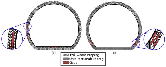
Figure 3.
First four layers of preform for (a) AT and (b) MA1 and MA2.
Figure 4 depicts the preform wrapped around the arbor before molding. Each completed preform with the arbor was placed inside matched-metal mold halves attached to a hydraulic press that had been preheated to 160 °C using embedded cartridge heaters and heated platens.
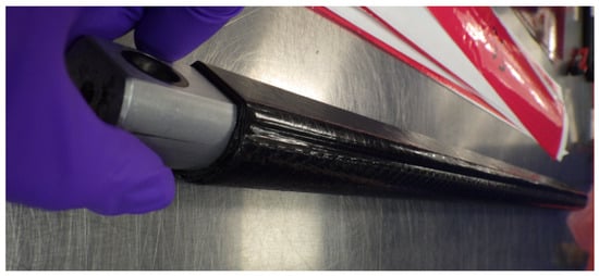
Figure 4.
Preform prepared by wrapping prepreg plies around the metallic arbor prior to molding.
2.4. Mechanical Characterization
A comprehensive suite of mechanical tests were conducted to characterize both the uncured prepregs and the fully cured composites. The mechanical tests were conducted on a United Testing System (UTS) SFM-20 test frame with a 1000-pound force transducer for the prepregs and a 20,000-pound force transducer for the cured composite plaques. For the prepregs, in-plane shear behavior was evaluated using the picture frame test method (ASTM D8067 [36]) for woven prepreg and the bias extension test for UD prepreg. The pierce cantilever test (ASTM D1388 [37]) was used to assess out-of-plane bending stiffness. Additionally, tensile moduli of uncured prepreg materials were obtained according to ISO 13934-1 [38]. The pressure–thickness response of the prepregs was quantified by studying the compaction behavior of prepreg stacks under a constant strain rate in compression. For the cured composites, ASTM D3039 [39] was employed to determine the tensile modulus above and below the glass transition temperature (), while ASTM D7078 [40] was used to evaluate shear modulus under the same thermal conditions. These mechanical properties informed the forming and molding simulations and ensured accurate representation of material anisotropy, shear compliance, and compaction behavior.
2.5. Thermal Characterization
Thermal properties were characterized to support accurate simulation of temperature-dependent material behavior during forming, consolidation, and molding. The cure kinetics model parameters of the resin in the prepreg were determined from isothermal cure runs conducted at different temperatures using a differential scanning calorimeter (DSC, Q2000, TA Instruments, New Castle, DE, USA). The coefficient of thermal expansion (CTE) was measured above and below according to ASTM E831 [41] using a thermomechanical analyzer (TMA, Q400, TA Instruments, New Castle, DE, USA), while ASTM E2585 [42] was employed to determine thermal diffusivity via the flash method using a laser flash apparatus (LFA 447, Netzsch, Selb, Germany). From these data, thermal conductivity was also calculated. These thermal measurements were essential for modeling heat transfer and resin softening during processing. In cured composites, the variation in thermomechanical behavior with temperature, particularly across the , was critical for defining the transition between rubbery and glassy response regimes in both simulation and process control.
2.6. Forming, Molding, and Cooling
The mold was closed on the layup around the arbor, with a pressure of 0.276 MPa (40 psi). The cure cycle consisted of an isothermal hold at 160 °C for 15 min, followed by a temperature ramp to 180 °C over 10 min, and then a final hold at 180 °C for another 20 min. This schedule allowed for the complete curing of the prepreg layers. After curing, cooling was initiated by circulating water at 20 °C through internal channels in both mold halves at a flow rate of 0.2 L/s, until the part temperature reached approximately 80 °C. The mold was then opened, and the molded composite beam was removed from both the tool and the arbor. The molded beam was allowed to cool in air to room temperature. The ends of the molded parts were subsequently trimmed to remove excess cured resin and prepare the specimens for dimensional measurement and characterization. Figure 5 depicts the cured part following demolding.
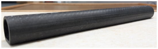
Figure 5.
Composite laminate after demolding.
3. Model Simulations
The entire manufacturing sequence of preform generation, forming and consolidation, molding, and demolding was simulated using the finite element method, as implemented in the PAM-COMPOSITES (v2021.0) software suite. This environment enabled integrated thermomechanical modeling of draping, compaction, curing, heat transfer, and distortion in composite laminates [8,43,44,45,46]. Simulations were performed under idealized conditions of a defect-free layup, and this was confirmed by visual inspection of the prepreg layups and molded composite beams. This modeling choice was consistent with experimental observations, as no visible preforming-related defects were identified in the molded parts. The modeling framework provided a unified representation of laminate deformation, consolidation, and residual stress evolution throughout the process. By coupling experimental boundary conditions with the pressure–thickness response and the measured prepreg and cured-sheet properties, the simulations predicted trends in the final thickness distribution of the molded part’s geometry.
3.1. Forming, Compaction, and Contact Modeling
The forming process was simulated using a nonlinear finite element formulation based on Kirchhoff–Love thin-shell kinematics [47,48,49,50]. This allowed for accurate representation of in-plane stretching and out-of-plane bending of the slender prepreg plies, while neglecting transverse shear [17,51]. The in-plane stress and bending moment resultants were expressed as follows:
where and are the membrane strain and curvature vectors, respectively, and is the thermal expansion coefficient vector. The evolution of laminate thickness under applied pressure was incorporated via the addition of a pressure-dependent compaction law, in which the local thickness was defined as a function of initial thickness and local pressure, . This ensured that the local thickness and stiffness evolved continuously during consolidation, reflecting the coupled influence of tool pressure and fiber bed compaction.
Inter-ply and tool–ply interactions were modeled using nonlinear contact mechanics with a penalty formulation for normal contact and a viscous shear model for tangential resistance. The penalty formulation ensured that contacting plies would not displace further. The tangential traction was related to viscous shear in a resin film of effective thickness , as follows:
where is the temperature-dependent resin viscosity, and V is the local sliding velocity. The effective friction coefficient was thereby obtained as follows:
The viscous friction model captured the strong dependence of inter-ply slip resistance on temperature, pressure, and slip rate, providing realistic resin-mediated frictional behavior. The nonlinear equilibrium equations were solved iteratively, ensuring consistent coupling among temperature, deformation, and interfacial mechanics.
3.2. Curing
Non-isothermal curing was simulated in PAM-RTM using transient anisotropic heat conduction with the exotherm of cure.
where is the local temperature, is the density, is the specific heat, and is the anisotropic thermal conductivity tensor. is the total heat of reaction per unit mass. The degree of cure, , followed the Kamal–Sourour kinetics model [52]:
where and are the pre-exponential factors and activation energies, respectively, while m and n are reaction exponents. The computed temperature and cure histories were transferred as inputs to the subsequent simulation stage.
3.3. Cooling, Demolding, and Distortion
After cure completion, cooling and distortion were simulated in PAM-DISTORTION using a cure-hardening instantaneously linear–elastic model (CHILE). This approach is widely used for thermoset composites and relies on the phase change of the resin around the glass transition temperature by considering two different linear elastic behaviors for the rubbery () and glassy () states of the resin. Detailed inputs for the rubbery and glassy states of the molded epoxy carbon fiber composite were generated from measurements on molded plaques. This method has been shown to predict distortion in molded thermoset composites accurately [53].
4. Results and Discussion
4.1. Experimental Characterization of Molded Parts
Figure 6 shows the cross-section of the three molded composite beams after the parts were demolded. All molded beams were visually inspected after production and prior to testing to check for external defects such as surface cracks and delamination; no visible defects were observed. Differential scanning calorimetry on pieces from these parts confirmed an average cure completion of 98.6% after demolding in all three cases, indicating full cross-linking of the resin system. It is evident that the flat portion in AT is thicker than the other areas; in MA1, the flat is thinner than the other areas; in MA2, the thickness appears to be very similar in both the flat and curved regions. The dimensions and part thicknesses recorded in different regions were labeled as shown in Figure 7 for tabulation.
Figure 6.
Cross-sectional view of molded beams: (a) AT, (b) MA1, and (c) MA2.
Figure 7.
Schematic of the D-shaped composite part showing key geometric parameters: overall diameter, height, flat thickness (), and curved section thickness ().
The thickness recorded in the flat region () of the molded part, as shown in Table 1, was averaged over 10 locations, with a standard deviation around 1%. The thickness recorded as in Table 1 was measured at the apex; that is, opposite to the flat region. The departure of measured dimensions from the reference design values is tabulated in Table 2. The AT laminate showed appreciable departure from the reference design thickness. Particularly, the thickness in the flat region () was higher than the reference by 5.4%. With the MA2 laminate, the thickness in the flat region was only 2% lower than the reference. This is comparable to the thickness deviation of 1.9% achieved on a compression-molded oar, using a pressure-intensifying membrane [34]. The comparison of molded part thickness in the flat region between the mixed layup MA2 and the AT layup is to be expected, because the twill-weave prepregs were less compressible than the UD prepregs. In addition, the thickness of the flat region in the molded part from the AT laminate was higher than the design value, as predicted by the simulations presented in Section 4.4. The pressure in the flat region of the AT laminate after forming was lower, as shown by the results of the numerical simulations presented in Section 4.4.

Table 1.
Measured dimensions of molded parts.
Table 2.
Deviations from design dimensions of molded parts from different laminates.
A comparison of other dimensions of molded beams, as shown in Table 2, indicates that MA1 exhibited the largest deviations from the design geometry, with the overall diameter and height decreasing by 4.0% and 5.2%, respectively. The MA2 hybrid laminate demonstrated the highest dimensional accuracy. For the MA2 laminate, the overall diameter and height differed by just +0.3% and −0.6%, respectively.
Following the dimensional evaluation, 305 mm long sections were extracted from the midspan of the molded beams and tested in three-point bending. The resulting flexural properties are summarized along with the average fiber volume fraction () in Table 3. The hybrid laminate containing the larger UD sub-stack (MA2) exhibited the highest flexural modulus, at 8.3 GPa, representing an approximately 8% increase relative to the all-twill configuration (7.7 GPa). The flexural strength values were very close (45.4 MPa and 45.2 MPa), suggesting no appreciable difference, consistent with the similar fiber content among the laminates. The improvement in flexural modulus for the more UD-rich hybrid laminate is consistent with its more uniform consolidation and closer adherence to the target thickness profile. Enhanced compaction reduces local resin-rich regions, minimizes thickness variability, and improves pressure distribution, all of which contribute to more efficient load transfer under bending. This result demonstrates that achieving proper through-thickness consolidation not only improves geometric accuracy during molding but also directly enhances the stiffness and mechanical reliability of the final component.
Table 3.
Flexural properties of molded composite beams.
4.2. Experimental Inputs for Forming Simulations
The pressure distribution developed at the end of forming, together with the temperature profile achieved at the end of curing, determines the residual stress state in the molded composite and, consequently, the final dimensional accuracy and distortion. For complex shapes, the local pressure varies along the surface, differing from the external pressure of the press platens. Twill-weave and UD plies exhibit distinct compaction and bending behaviors under the same applied load. Hence, the two types of prepreg were characterized in terms of shear, bending, and compaction. Four samples of prepreg were used for each type of test. The fiber volume fractions of the twill-weave–epoxy prepreg and the UD–epoxy prepreg were 0.45 and 0.54, respectively.
The shear response of the twill-weave prepreg with a fiber volume fraction of 0.45 was characterized using the picture frame test. Shear stress–angle data were derived from the load–displacement curves using
where is the shear stress, F is the measured load, and t are the specimen length and thickness, respectively, and is the measured extension. The critical shear angle () for the twill-weave prepreg was found to be 37°. The shear behavior was modeled using a modified exponential function:
where a = 1.9519, b = 0.0028, and c = 0.2196 are fitted parameters for the twill-weave prepreg. This expression was chosen over the common pure exponential because it better captures the linear response at small angles while preserving nonlinear stiffening at larger deformations. This formulation efficiently represents the transition from fiber reorientation to tow interlocking and is well suited for process-level simulations requiring rapid shear evaluation [54,55]. Figure 8 presents the experimental shear force–angle response along with the corresponding modified exponential fit. The simulations predicted that the maximum shear angle reached at the end of the forming simulation was 28°, which was well below the critical shear angle of 37°, and confirmed the absence of wrinkling during the experimental molding runs.
Figure 8.
Experimental shear stress vs. angle data and modified exponential fit.
The bending response of the prepregs was characterized using the Pierce cantilever test. The deflected profiles presented in Figure 9 were modeled using a modified cosine function:
where A, B, and C are fitted parameters, s is the arc length, and L is the overhang length. This formulation extends the classical cosine sag to capture asymmetry and skew arising from anisotropic stiffness. The curvature was obtained from
and the bending moment due to self-weight was approximated as follows:
where w is the weight per unit length. The effective bending modulus was calculated using geometric analysis of the cantilever data:
where M is the bending modulus, G is the flexural rigidity, and t is the ply thickness. All of the fitted parameters for shear and bending behavior are listed in Table 4. The results show that the UD prepreg (axial direction) exhibited the highest stiffness, followed by the twill-weave and UD transverse orientations. The analytical fitting approach provides a computationally efficient means to evaluate curvature and stiffness across laminate types, consistent with simplified modeling frameworks for prepreg deformation [56,57].
Figure 9.
(a) Experimental draped shapes of twill and UD prepregs in axial and transverse directions. (b) Displacement profiles along arc length with modified cosine fits. (c) Calculated moment–curvature response derived from fitted profiles.
Table 4.
Fitting parameters of prepreg materials for bending behavior.
The compaction response was characterized by compressing a 6-ply stack (254 mm × 254 mm) of each type of prepreg at a constant closing rate, until the applied external pressure reached 40 psi or 0.276 MPa. The pressure was recorded along with the stack thickness over time during this process. Plots of stack thickness against pressure for the twill-weave and UD prepregs are presented in Figure 10. The following relation with two parameters was selected to fit these plots:
where is the initial thickness, h is the thickness at pressure p, and a is a stiffness parameter. The fitted parameters are listed in Table 5. This relation is similar to the one proposed by Hubert and Poursartip [58]. This information supplements the in-plane kinematics described by the Kirchhoff–Love framework.
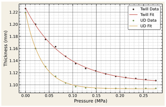
Figure 10.
Experimental pressure–thickness data and fitted exponential compaction curves for both twill-weave and UD prepregs.
Table 5.
Exponential compaction-law parameters for twill-weave and UD prepregs.
Other inputs, including thermomechanical material properties used for simulations of the molding and cooling processes, are tabulated in Appendix A. Five samples were cut out from molded plaques for each test condition. The standard deviation in the measured moduli was around 2.3%, while that for for the measured CTEs was around 1.8%.
4.3. Predicted and Measured Part Dimensions
The predicted part dimensions from the simulations were in excellent agreement with the experimentally measured dimensions (see Table 6); the deviations were within ±0.2 mm across all attributes. This validates the accuracy of the simulation model.
Table 6.
Comparison of predicted and experimentally measured part dimensions.
Consequently, the simulated pressure distributions at the end of forming may be used to interpret the measured dimensional variations among the various laminate designs. Differences in bending and compaction behavior between twill and unidirectional plies produced distinct local pressure variations.
4.4. Pressure Distributions from Simulations
As shown in Figure 10, the UD prepreg exhibits a steep compaction curve and approaches a nearly rigid state beyond approximately 0.12 MPa, after which additional pressure produces negligible thickness reductions. In contrast, the twill-weave prepreg continues to compress gradually at higher pressures, reflecting its greater compliance under through-thickness loading. In mixed-architecture laminates, this difference leads to a natural pressure redistribution mechanism: once the UD plies reach full compaction, further applied pressure is transferred to adjacent woven regions that remain more deformable. Consequently, the inclusion of UD plies within a predominantly woven layup promotes a more balanced pressure field during mold closure, enabling improved consolidation of the twill layers, particularly in regions of complex curvature.
The predicted pressure distributions for the three laminate configurations at the end of the forming stage are presented in Figure 11. In the AT laminate, the woven architecture required a higher local pressure to achieve full compaction; as a result, under the applied pressure distribution, the prepreg layers remained partially compacted, leading to non-uniform consolidation. The MA1 laminate achieved local compaction of the UD plies but lacked sufficient UD layers to transmit pressure effectively toward the top surface, resulting in under-compaction in the curved region and a pronounced thickness gradient. The MA2 configuration exhibited the most balanced response. The thicker UD sub-stack reached full compaction at the base and acted as an efficient load-transfer medium during mold closure.
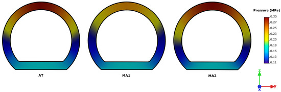
Figure 11.
Pressure distribution along the cross-sections of AT, MA1, and MA2.
Figure 12 shows the pressure distribution plots along the curvature of the part for the three preform configurations. Once compacted, the stiffened UD layers redirected pressure toward the twill-weave layers, homogenizing the local pressure field and achieving consolidation uniformity. This redistribution reduced curvature-induced thinning and produced a molded geometry that most closely matched the reference design dimensions.
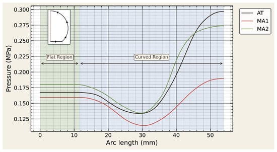
Figure 12.
Predicted pressure distribution along the surface of the D-shaped composite beam.
In the AT laminate, inadequate pressure values through the woven stack resulted in incomplete consolidation across the entire laminate, producing a thickness variation along the profile that was outside tolerances. In the MA1 laminate, although the UD sub-stack reached full compaction, the limited quantity of UD layers constrained effective pressure transmission. Consequently, the upper curved region remained under-compacted, producing a pronounced through-thickness gradient. This imbalance manifested as an under-thickened flat region relative to the design specification, while the curved apex accumulated excess thickness compared to the reference geometry. The MA2 laminate, benefiting from full UD compaction at the base and efficient pressure redistribution into the twill sub-stack, developed the most uniform thickness profile. The redistributed pressure suppressed curvature-driven thickness variation and enabled the molded geometry to remain close to the design thickness across both the flat and curved regions. Overall, these results highlight how laminate architecture governs compaction of the preform during molding.
5. Conclusions
The dimensional accuracy of compression-molded D-shaped composite beams is remarkably greater with the use of a hybrid layup of twill-weave fabric prepregs in the curved section and UD prepregs in the flat section. With the MA2 laminate, the thickness in the flat region was only 2% lower than the reference design. Experimental consolidation tests established that the AT laminate was less compressible than the mixed layup MA2 leading to a thickness in the flat region that was 5.4% higher than the reference design. Forming simulations carried out with detailed measured inputs were validated by excellent comparison between the predicted dimensions of the demolded part and experimentally measured values. The forming simulations accurately predicted the thickness trends and local deviations for all three laminate configurations. Hence, the predicted pressure distributions within the compacted preforms provide insight into laminate designs that achieve the desired part thickness and overall dimensional accuracy for compression molding of D-shaped cross-sections.
Author Contributions
Conceptualization, S.S. and K.J.; methodology, S.S. and K.J.; software, S.S.; validation, S.S. and K.J.; formal analysis, S.S. and K.J.; investigation, S.S. and K.J.; resources, K.J.; data curation, S.S.; writing—original draft preparation, S.S.; writing—review and editing, K.J.; visualization, S.S.; supervision, K.J.; project administration, K.J.; funding acquisition, K.J. All authors have read and agreed to the published version of the manuscript.
Funding
This research was funded by Domico Med-Device, Fenton, MI, project no. 56305.
Data Availability Statement
All data supporting the findings of this study are presented within the article. Any additional inquiries may be directed to the corresponding author.
Conflicts of Interest
The authors declare no conflicts of interest. The funders had no role in the design of the study; in the collection, analyses, or interpretation of data; in the writing of the manuscript; or in the decision to publish the results.
Appendix A. Material Property Inputs for Cure and Distortion Simulations
Table A1.
Combined mechanical properties for cure simulations.
Table A1.
Combined mechanical properties for cure simulations.
| Material | Property | Value |
|---|---|---|
| Resin | Density | 1.25 g/cc |
| Thermal Conductivity | 0.15 W/(m.K) | |
| Specific Heat Capacity | 1100 J/(kg.K) | |
| Heat of Reaction | 114.68 J/g | |
| 64,054 J/mol | ||
| 77,684 J/mol | ||
| s−1 | ||
| s−1 | ||
| m | 0.36 | |
| n | 1.64 | |
| Fiber | Density | 1.80 g/cc |
| Thermal Conductivity || | 150 W/(m.K) | |
| Thermal Conductivity ⊥ | 15 W/(m.K) | |
| Specific Heat Capacity | 0.71 J/(g.K) |
|| Along fiber direction. ⊥ Transverse to fiber direction.
Table A2.
Cured composite property inputs for distortion simulation.
Table A2.
Cured composite property inputs for distortion simulation.
| Property | Twill Weave | UD |
|---|---|---|
| Density (g/cc) | 1.50 | 1.55 |
| Fiber Volume Fraction (%) | 44.9 | 54.2 |
| Gel-Point Conversion (%) | 55 | |
| Tg0 (K) | 260.15 | |
| (K) | 476.65 | |
| Below | ||
| Young’s Modulus [x] (GPa) | 7.9 | 19.6 |
| Young’s Modulus [y] (GPa) | 7.9 | 4.7 |
| Young’s Modulus [z] (GPa) | 6.5 | 4.7 |
| Poisson’s Ratio [xy] | 0.22 | 0.31 |
| Poisson’s Ratio [yz] | 0.18 | 0.23 |
| Poisson’s Ratio [xz] | 0.18 | 0.23 |
| Shear Modulus [xy] (GPa) | 3.24 | 2.48 |
| Shear Modulus [yz] (GPa) | 2.35 | 2.17 |
| Shear Modulus [xz] (GPa) | 2.35 | 2.17 |
| CTE [x] (µm/m°C) | 1.4 | 0.7 |
| CTE [y] (µm/m°C) | 1.4 | 48.6 |
| CTE [z] (µm/m°C) | 43.9 | 48.6 |
| Above | ||
| Young’s Modulus [x] (GPa) | 303.7 | 453.1 |
| Young’s Modulus [y] (GPa) | 303.7 | 126.7 |
| Young’s Modulus [z] (GPa) | 270.6 | 126.7 |
| Poisson’s Ratio [xy] | 0.28 | 0.34 |
| Poisson’s Ratio [yz] | 0.25 | 0.31 |
| Poisson’s Ratio [xz] | 0.25 | 0.31 |
| Shear Modulus [xy] (GPa) | 118.6 | 169.1 |
| Shear Modulus [yz] (GPa) | 121.5 | 48.4 |
| Shear Modulus [xz] (GPa) | 121.5 | 48.4 |
| CTE [x] (µm/m°C) | 2.3 | 1.87 |
| CTE [y] (µm/m°C) | 2.3 | 123 |
| CTE [z] (µm/m°C) | 107 | 123 |
References
- Han, N.; Ahmed, I.; Parsons, A.J.; Harper, L.; Scotchford, C.A.; Scammell, B.E.; Rudd, C.D. Influence of screw holes and gamma sterilization on properties of phosphate glass fiber-reinforced composite bone plates. J. Biomater. Appl. 2013, 27, 990–1002. [Google Scholar] [CrossRef] [PubMed]
- Chua, C.Y.X.; Liu, H.C.; Di Trani, N.; Susnjar, A.; Ho, J.; Scorrano, G.; Rhudy, J.; Sizovs, A.; Lolli, G.; Hernandez, N.; et al. Carbon fiber reinforced polymers for implantable medical devices. Biomaterials 2021, 271, 120719. [Google Scholar] [CrossRef] [PubMed]
- Morris, R.H.; Geraldi, N.R.; Stafford, J.L.; Spicer, A.; Hall, J.; Bradley, C.; Newton, M.I. Woven Natural Fibre Reinforced Composite Materials for Medical Imaging. Materials 2020, 13, 1684. [Google Scholar] [CrossRef]
- Scholz, M.S.; Blanchfield, J.P.; Bloom, L.D.; Coburn, B.H.; Elkington, M.; Fuller, J.D.; Gilbert, M.E.; Muflahi, S.A.; Pernice, M.F.; Rae, S.I.; et al. The use of composite materials in modern orthopaedic medicine and prosthetic devices: A review. Compos. Sci. Technol. 2011, 71, 1791–1803. [Google Scholar] [CrossRef]
- Lee, J.M.; Lee, C.J.; Kim, B.M.; Ko, D.C. Design of Prepreg Compression Molding for Manufacturing of CFRTP B-pillar Reinforcement with Equivalent Mechanical Properties to Existing Steel Part. Int. J. Precis. Eng. Manuf. 2020, 21, 545–556. [Google Scholar] [CrossRef]
- Gong, Y.; Xu, P.; Peng, X.; Wei, R.; Yao, Y.; Zhao, K. A lamination model for forming simulation of woven fabric reinforced thermoplastic prepregs. Compos. Struct. 2018, 196, 89–95. [Google Scholar] [CrossRef]
- Boisse, P.; Hamila, N.; Madeo, A. Modelling the development of defects during composite reinforcements and prepreg forming. Philos. Trans. R. Soc. A Math. Phys. Eng. Sci. 2016, 374, 20150269. [Google Scholar] [CrossRef] [PubMed]
- Bae, D.; Kim, S.; Lee, W.; Yi, J.W.; Um, M.K.; Seong, D.G. Experimental and Numerical Studies on Fiber Deformation and Formability in Thermoforming Process Using a Fast-Cure Carbon Prepreg: Effect of Stacking Sequence and Mold Geometry. Materials 2018, 11, 857. [Google Scholar] [CrossRef]
- Dodwell, T.; Butler, R.; Hunt, G. Out-of-plane ply wrinkling defects during consolidation over an external radius. Compos. Sci. Technol. 2014, 105, 151–159. [Google Scholar] [CrossRef]
- Tamagawa, T.; Mori, Y.; Minakuchi, S. Consolidation mechanism of composite corners cured on convex and concave tools. Compos. Part A Appl. Sci. Manuf. 2023, 169, 107500. [Google Scholar] [CrossRef]
- Bae, J.H.; Han, M.G.; Chang, S.H. Formability of complex composite structures with ribs made of long carbon-fiber-reinforced prepregs. Compos. Struct. 2017, 168, 56–64. [Google Scholar] [CrossRef]
- Potter, K. In-plane and out-of-plane deformation properties of unidirectional preimpregnated reinforcement. Compos. Part A Appl. Sci. Manuf. 2002, 33, 1469–1477. [Google Scholar] [CrossRef]
- Chowdhury, I.R.; Summerscales, J. Woven Fabrics for Composite Reinforcement: A Review. J. Compos. Sci. 2024, 8, 280. [Google Scholar] [CrossRef]
- Kim, J.Y.; Hwang, Y.T.; Baek, J.H.; Song, W.Y.; Kim, H.S. Study on inter-ply friction between woven and unidirectional prepregs and its effect on the composite forming process. Compos. Struct. 2021, 267, 113888. [Google Scholar] [CrossRef]
- Liu, H.; Falzon, B.G.; Tan, W. Experimental and numerical studies on the impact response of damage-tolerant hybrid unidirectional/woven carbon-fibre reinforced composite laminates. Compos. Part B Eng. 2018, 136, 101–118. [Google Scholar] [CrossRef]
- Kim, S.; Shin, H.; Lee, K.; Ha, S. Enhancing Product Performance via a Modified Double-Diaphragm Forming (mDDF) Preform Method for Prepreg Compression Molding of Fiber-Reinforced Polymer Composites. Polymers 2025, 17, 1489. [Google Scholar] [CrossRef] [PubMed]
- Mulye, P.D.; Morançay, L.; Binetruy, C.; Comas-Cardona, S.; Leygue, A.; Guillon, D. Unified numerical process modeling of forming and consolidation for thermoplastic composites with prepreg patches. Front. Mater. 2023, 10, 1176482. [Google Scholar] [CrossRef]
- Pasco, C. Prepreg Forming Numerical Analysis and Experimental Characterisation for a Novel High-Volume Forming Process. Ph.D. Thesis, University of Warwick, Coventry, UK, 2018. [Google Scholar]
- Kogiso, N.; Watson, L.T.; Gürdal, Z.; Haftka, R.T. Genetic algorithms with local improvement for composite laminate design. Struct. Optim. 1994, 7, 207–218. [Google Scholar] [CrossRef]
- Callahan, K.J.; Weeks, G.E. Optimum design of composite laminates using genetic algorithms. Compos. Eng. 1992, 2, 149–160. [Google Scholar] [CrossRef]
- Almeida, F.S.; Awruch, A.M. Design optimization of composite laminated structures using genetic algorithms and finite element analysis. Compos. Struct. 2009, 88, 443–454. [Google Scholar] [CrossRef]
- Park, J.H.; Hwang, J.H.; Lee, C.S.; Hwang, W. Stacking sequence design of composite laminates for maximum strength using genetic algorithms. Compos. Struct. 2001, 52, 217–231. [Google Scholar] [CrossRef]
- Albazzan, M.A.; Harik, R.; Tatting, B.F.; Gürdal, Z. Efficient design optimization of nonconventional laminated composites using lamination parameters: A state of the art. Compos. Struct. 2019, 209, 362–374. [Google Scholar] [CrossRef]
- Hochard, C. Optimum design of laminated composite structures. Compos. Struct. 2004, 63, 159–165. [Google Scholar] [CrossRef]
- Belnoue, J.P.H.; Nixon-Pearson, O.; Ivanov, D.; Hallet, S.R. Numerical and experimental investigation of prepreg compaction for defect formation mechanisms. In Design, Manufacturing and Applications of Composites, Proceedings of the Tenth Joint Canada–Japan Workshop on Composites, Vancouver, BC, Canada, 4–6 August 2014; DEStech Publications, Inc.: Lancaster, PA, USA, 2015. [Google Scholar]
- Gangloff, J.J.; Simacek, P.; Sinha, S.; Advani, S.G. A process model for the compaction and saturation of partially impregnated thermoset prepreg tapes. Compos. Part A Appl. Sci. Manuf. 2014, 64, 234–244. [Google Scholar] [CrossRef]
- Nguyen, Q.T.; Vidal-Sallé, E.; Boisse, P.; Park, C.H.; Saouab, A.; Bréard, J.; Hivet, G. Mesoscopic scale analyses of textile composite reinforcement compaction. Compos. Part B Eng. 2013, 44, 231–241. [Google Scholar] [CrossRef]
- Xiong, H. Simulation of Forming, Compaction and Consolidation of Thermoplastic Composites Based on Solid Shell Elements. Ph.D. Thesis, Université de Lyon, Lyon, France, 2017. [Google Scholar]
- Rashidi, A.; Belnoue, J.P.H.; Thompson, A.J.; Hallett, S.R.; Milani, A.S. Consolidation-driven wrinkling in carbon/epoxy woven fabric prepregs: An experimental and numerical study. Compos. Part A Appl. Sci. Manuf. 2021, 143, 106298. [Google Scholar] [CrossRef]
- Hallander, P.; Akermo, M.; Mattei, C.; Petersson, M.; Nyman, T. An experimental study of mechanisms behind wrinkle development during forming of composite laminates. Compos. Part A Appl. Sci. Manuf. 2013, 50, 54–64. [Google Scholar] [CrossRef]
- Bai, R.; Chen, B.; Colmars, J.; Boisse, P. Physics-based evaluation of the drapability of textile composite reinforcements. Compos. Part B Eng. 2022, 242, 110089. [Google Scholar] [CrossRef]
- Hubert, P.; Kratz, J. Tool interface pressure during the forming of model composite corners. Compos. Part A Appl. Sci. Manuf. 2021, 151, 106639. [Google Scholar] [CrossRef]
- Maes, V.K.; Minakuchi, S.; Chandarana, N.; Kratz, J. Shape change of composite corners due to tooling pressure distribution effects. Compos. Part A Appl. Sci. Manuf. 2025, 196, 108924. [Google Scholar] [CrossRef]
- Walczyk, D.; Kuppers, J.; Hoffman, C. Curing and Consolidation of Advanced Thermoset Composite Laminate Parts by Pressing Between a Heated Mold and Customized Rubber-Faced Mold. J. Manuf. Sci. Eng. 2011, 133, 011002. [Google Scholar] [CrossRef]
- Garofalo, J.; Walczyk, D.; Kuppers, J. Rapid Consolidation and Curing of Vacuum-Infused Thermoset Composite Parts. J. Manuf. Sci. Eng. 2016, 139, 021010. [Google Scholar] [CrossRef]
- D8067/D8067M-17; Standard Test Method for In-Plane Shear Properties of Sandwich Panels Using a Picture Frame Fixture. ASTM International: West Conshohocken, PA, USA, 2017; reapproved 2025.
- D1388-23; Standard Test Method for Stiffness of Fabrics. ASTM International: West Conshohocken, PA, USA, 2023.
- ISO 13934-1:2013; Textiles—Tensile Properties of Fabrics—Part 1: Determination of Maximum Force and Elongation at Maximum Force Using the Strip Method. International Organization for Standardization: Geneva, Switzerland, 2013.
- D3039/D3039M-17; Standard Test Method for Tensile Properties of Polymer Matrix Composite Materials. ASTM International: West Conshohocken, PA, USA, 2017; reapproved 2025.
- D7078/D7078M-20; Standard Test Method for Shear Properties of Composite Materials by V-Notched Rail Shear Method. ASTM International: West Conshohocken, PA, USA, 2020; reapproved 2025.
- E831-25; Standard Test Method for Linear Thermal Expansion of Solid Materials by Thermomechanical Analysis. ASTM International: West Conshohocken, PA, USA, 2025.
- E2585-09; Standard Practice for Thermal Diffusivity by the Flash Method. ASTM International: West Conshohocken, PA, USA, 2009; reapproved 2022.
- Poodts, E.; Minak, G.; Mazzocchetti, L.; Giorgini, L. Fabrication, process simulation and testing of a thick CFRP component using the RTM process. Compos. Part B Eng. 2014, 56, 673–680. [Google Scholar] [CrossRef]
- Zhang, Y.; An, L.; Zhao, C. Enhancing the Forming Accuracy of CFRP through a Global Compensation Method by Introducing an Optimal Profile. Polymers 2024, 16, 1792. [Google Scholar] [CrossRef] [PubMed]
- Qian, C.; Weare, R.; Pasco, C.; Kourra, N.; Attridge, A.; Williams, M.; Kendall, K. Numerical and Experimental Studies of Multi-ply Woven Carbon Fibre Prepreg Forming Process. Procedia Manuf. 2020, 47, 93–99. [Google Scholar] [CrossRef]
- Lee, W.; Um, M.K.; Byun, J.H.; Boisse, P.; Cao, J. Numerical study on thermo-stamping of woven fabric composites based on double-dome stretch forming. Int. J. Mater. Form. 2010, 3, 1217–1227. [Google Scholar] [CrossRef]
- Nguyen, D.T.A.; Li, L.; Ji, H. Stable and accurate numerical methods for generalized Kirchhoff–Love plates. J. Eng. Math. 2021, 130, 6. [Google Scholar] [CrossRef]
- Ozenda, O.; Virga, E.G. On the Kirchhoff-Love Hypothesis (Revised and Vindicated). J. Elast. 2021, 143, 359–384. [Google Scholar] [CrossRef]
- Kiendl, J.; Bletzinger, K.U.; Linhard, J.; Wüchner, R. Isogeometric shell analysis with Kirchhoff–Love elements. Comput. Methods Appl. Mech. Eng. 2009, 198, 3902–3914. [Google Scholar] [CrossRef]
- Nguyen-Thanh, N.; Valizadeh, N.; Nguyen, M.N.; Nguyen-Xuan, H.; Zhuang, X.; Areias, P.; Zi, G.; Bazilevs, Y.; De Lorenzis, L.; Rabczuk, T. An extended isogeometric thin shell analysis based on Kirchhoff–Love theory. Comput. Methods Appl. Mech. Eng. 2015, 284, 265–291. [Google Scholar] [CrossRef]
- Yu, W. A unified theory for constitutive modeling of composites. J. Mech. Mater. Struct. 2016, 11, 379–411. [Google Scholar] [CrossRef]
- Kamal, M.R.; Sourour, S. Kinetics and thermal characterization of thermoset cure. Polym. Eng. Sci. 1973, 13, 59–64. [Google Scholar] [CrossRef]
- Shree, S.; Jayaraman, K.; Dereims, A.; Raveendra, R. Performance of additively manufactured composite mold with uniform fiber orientation. Int. J. Adv. Manuf. Technol. 2024, 131, 4297–4305. [Google Scholar] [CrossRef]
- Wang, Y.; Zhang, W.; Ren, H.; Huang, Z.; Geng, F.; Li, Y.; Zhu, Z. An Analytical Model for the Tension-Shear Coupling of Woven Fabrics with Different Weave Patterns under Large Shear Deformation. Appl. Sci. 2020, 10, 1551. [Google Scholar] [CrossRef]
- Kahavita, K.D.H.N.; McCarthy, E.D.; Zhang, M.; Brádaigh, C.M.Ó.; Harrison, P. Characterising the shear resistance of a unidirectional non-crimp glass fabric using modified picture frame and uniaxial bias extension test methods. Int. J. Mater. Form. 2023, 16, 49. [Google Scholar] [CrossRef]
- Alshahrani, H.; Hojjati, M. A new test method for the characterization of the bending behavior of textile prepregs. Compos. Part A Appl. Sci. Manuf. 2017, 97, 128–140. [Google Scholar] [CrossRef]
- Li, Z.; Song, Q.; Liu, J.; Liu, W.; Chen, P.; Yue, G. Modeling of Preforming Process for Unidirectional Prepreg Composites Using Simplified Linear Friction Model and Fiber-Tracking Method. Polymers 2025, 17, 1321. [Google Scholar] [CrossRef]
- Hubert, P.; Poursartip, A. A method for the direct measurement of the fibre bed compaction curve of composite prepregs. Compos. Part A Appl. Sci. Manuf. 2001, 32, 179–187. [Google Scholar] [CrossRef]
Disclaimer/Publisher’s Note: The statements, opinions and data contained in all publications are solely those of the individual author(s) and contributor(s) and not of MDPI and/or the editor(s). MDPI and/or the editor(s) disclaim responsibility for any injury to people or property resulting from any ideas, methods, instructions or products referred to in the content. |
© 2026 by the authors. Licensee MDPI, Basel, Switzerland. This article is an open access article distributed under the terms and conditions of the Creative Commons Attribution (CC BY) license.