1. Introduction
In situ automated fiber placement (AFP) has received more attention in recent years for its potential reduction in manufacturing time, particularly for aerospace applications [
1]. This time saving comes principally from the removal of autoclave consolidation from the production chain, instead relying on the high-temperature laser heating to achieve full consolidation rather than temporary bonding (as in other AFP processes) [
2]. This in turn opens the possibility of new, large-scale thermoplastic composites which are not limited by the size of an autoclave. High-performance polymers, like polyetheretherketone or polyetherimide, have been the subject of many in situ AFP investigations owing to their current use in fiber-reinforced aerospace components [
3]. Furthermore, thermoplastics have often been seen as having better recyclability compared to thermoset composites and thereby a more positive contribution to a circular economy [
4].
A main aspect to consider in the production of composites by AFP is the manufacturing of a mold [
5]. The current industry standard is the use of metallic molds [
6]. Inherent in these are high manufacturing costs, high material costs, long manufacturing times, and a high weight [
6]. An additional disadvantage of metallic molds is the difficulty of achieving an appropriate bond between the composite material and tooling surface, often resulting in damage to the final part or demolding during the lay-up process [
7].
Some of these limitations can be overcome with a method of manufacturing complex composite components using a system consisting of two cooperating robots which eliminates the need for a mold completely [
3,
8]. One robot is used as a movable substrate for the other robot to lay tapes on and support the laminate during the lay-up. The interlaminar shear strength of the samples manufactured with this technology was significantly greater compared to a conventionally manufactured laminate on a metallic surface. This was explained by a reduced cooling rate of the laminate due to the part having no contact with a mold which could direct energy away from the laminate. This may result in a higher crystallinity in the parts. A major drawback, however, is the low shape accuracy achievable with this technology compared to manufacturing in molds [
8].
A further approach to overcome the limitations of a metallic mold is the use of a polymeric mold. Prior studies [
9,
10] have demonstrated the principal suitability of polyamide 6 (PA6) as a mold material for the AFP of carbon-fiber-reinforced low-melt polyaryletherketone (CF/LM-PAEK). The incompatibility of both polymers was utilized to achieve a bond which is strong enough to secure a laminate in a mold during its manufacturing and allows for demolding afterwards. The thermoplastic nature of PA6 allows processing using additive manufacturing (AM) methods. Thus, molds can be 3D printed using large-scale extrusion-based AM facilities in a fraction of the production time of a metallic mold and at lower costs. It has been shown that multiple process parameters of the AFP have an influence on the bonding strength between tapes and mold [
9]. A higher consolidation pressure, low tape-tensioning forces in the lay-up direction, and high process temperatures are beneficial to the strength of the bond. However, PA6 differs in many aspects from aluminum as a substrate material. The most relevant differences are different thermal conductivity values, different Young’s moduli, and differing optimal process parameters for the first layer of the laminate.
The lower thermal conductivity of PA6, compared to aluminum, may result in a slower cooling of the tapes after placement. Pesetsktii et al. [
11] have shown that a fast cooling of a semi-crystalline polymer results in a lower crystallinity. For the AFP of carbon-fiber-reinforced polyetheretherketone, a cooling rate of ≥2500 K·min
−1 was found to result in the polymer being in a completely amorphous state [
12]. This is well below the cooling rate of >5000 K·min
−1 which can be expected in in situ AFP of PAEKs [
13]. A correlation between crystallinity and mechanical properties of composites has also been shown by Tierney et al. [
14] and Schiel et al. [
15]. Here, higher crystallinity in composites correlates with higher mechanical performance.
The differences in material stiffness between a metallic and a polymeric mold may influence the consolidation of tapes with another. Song et al. [
16] investigated the effect of the consolidation pressure on the void content in composites by varying the applied force between 400 N and 2000 N. It was found that a higher consolidation pressure results in a minimum in void content and indicates the highest mechanical properties among the specimens [
16]. It may be possible that the contact area between the consolidation roller of an AFP end effector and a tape can increase due to a more elastic substrate and that the distribution of the force acting on a tape may vary between substrates of different stiffnesses. According to the results of Song et al., this could result in a change in different mechanical properties of laminates [
16].
The comparatively low thermal conductivity of PA6 indicates a possible increase in mechanical properties of laminates manufactured on polymeric molds compared to ones manufactured on metallic molds, as argued above. However, certain process parameters of the AFP need adjustment when using PA6 as a mold material. Parameters like process temperature and consolidation pressure have been shown to have a significant influence on the mechanical properties of laminates [
16,
17]. A lower tape tension can also impact the interlaminar shear strength negatively [
18]. As is often the case with thermoplastic materials, an increase in process temperatures leads to an increase in the mechanical properties [
17]. Heating of a polymeric mold is, however, limited by the heat deflection temperature (HDT) of the polymer. The HDT of PA6 is significantly lower than the suggested mold temperatures of 200 °C [
17]. This will impair the crystallization and mechanical properties. Further, the composite tapes cannot be heated to the optimal temperature to ensure the PA6 will not degrade upon contact with the heated tape. This decrease in temperature will result in a weakened bonding of tapes and therefore lower mechanical properties [
17].
Notably, 3D-printable molds allow for a rapid manufacturing approach and direct bonding of tapes to the mold’s surface without the need for excessive surface preparation resulting in lower manufacturing costs and material usage. The necessary change of multiple factors of the AFP, which all have an effect of different sizes and directions on the properties of a laminate, makes it impossible to predict the total effect that the use of a polymeric mold has. To determine if laminates, which were manufactured in a polymeric mold, are of equal quality compared to laminates manufactured in metallic molds, this study compares mechanical and morphological characteristics of both types of laminates.
2. Materials and Methods
The basic structure of this study is shown in
Figure 1. At first, two quasi-isotropic CF/LM-PAEK laminates were manufactured using in situ AFP. One laminate was laid on a PA6 substrate while the other was manufactured using an aluminum substrate. The comparison of these two laminates, regarding mechanical and morphological characteristics, is the goal of this study. During the lay-up, the cooling rates of the first layer of the laminates were measured. After completion of the lay-up, specimens were separated from both laminates. Differential scanning calorimetry and scanning electron microscopy imaging were used to determine morphological characteristics, such as the distribution of crystallinity across the laminates’ cross-section and the difference in bulk crystallinity in both laminates. Tensile tests and five-point bending tests were conducted to determine any difference in mechanical properties.
2.1. Materials
For the automated fiber placement of the laminates, a thermoplastic prepreg consisting of CF/LM-PAEK which was reinforced with 55 vol% of carbon fibers was used. The prepreg was sourced through the company Suprem (Yverdon-les-Bains, Switzerland). The prepreg tapes had a width of 12.7 mm and a fiber mass fraction of 63.09%.
When using aluminum as the substrate for the AFP process, a first layer of thermoplastic prepreg was applied to the substrate using adhesive tape. This prepreg is used as the first ply of the laminate and allows the placement of the tapes of subsequent layers, since the tape laying directly on the (unmodified) metallic surface is nearly impossible as stated in the introduction. The prepreg Cetex TC 1225 was used for this purpose which was manufactured by Toray Advanced Composites (Morgan Hill, CA, USA).
For the AFP on a polymeric substrate, a casted sheet of 3 mm thick polyamide 6 was used which was purchased from the company BW Kunststoffe e.K. (Heilbronn, Germany). This material was dyed black to minimize reflection of the laser during the lay-up and has a melting temperature of 216 °C. Casted sheets of PA6 were used, instead of 3D-printed sheets, to minimize the possible effect of uncontrolled parameters in the 3D printing process.
2.2. Manufacturing Facilities
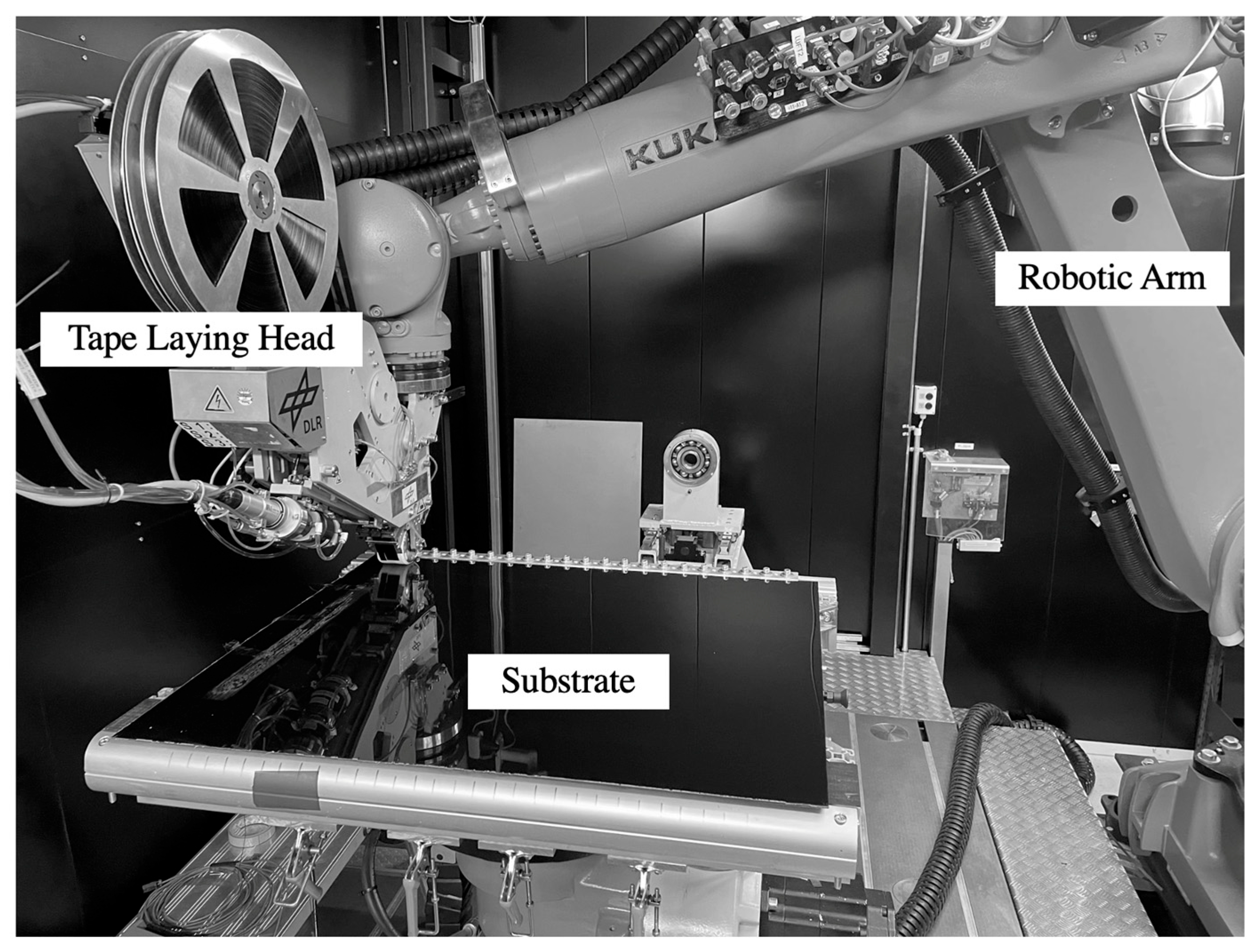
The automated fiber placement facility of the DLR in Stuttgart, Germany, was used for the manufacturing of the laminates and is shown in
Figure 2. The system consists of a 6-degree-of-freedom robotic arm, KUKA AG (Augsburg, Germany) Quantec KR210. The end effector of the robotic system is a tape-laying head produced by AFPT GmbH (Dörth, Germany). The head is able to place up to three 12.7 mm wide tapes at once. For this study, only one tape was placed at a time. Tapes were heated using a 1000 nm diode laser.
The process parameters used for the first ply of both laminates are listed in
Table 1. The remaining plies of both laminates were placed using a process temperature of 470 °C, a laser position of 0 mm (at the nip point), a force of 15 N in-plane with the tape, and a system pneumatic pressure of 6 bar, and the substrates remained unheated, thus at ambient temperature. The differing parameters for the first ply of both laminates are listed in
Table 1. The first ply parameters for the PA6 substrate were changed to a parameter set previously determined to yield good first ply adhesion without damaging the tool surface [
9].
2.3. Determining the Cooling Rate
The cooling rate was measured for the first automatically placed ply. For this purpose, 25 μm thick OMEGA Engineering (Deckenpfronn, Germany) type K thermocouples were placed on the PA6 sheet (for the polymeric mold) and on the prepreg applied to the metallic mold. Initially, multiple measurements were planned. However, due to the fragile nature of the thermocouples and limitations in time and materials, only one thermocouple per laminate was evaluated.
The cooling rate was calculated by determining the linear regression of all measurements during one second after the maximum in measured temperature (300 sampling values). An OMEGA Engineering OMB-DAQ-2416 measurement module was used for the measurement and recording of the temperature values. A sampling rate of 300 Hz and a resolution of 24 bits were used.
2.4. Differential Scanning Calorimetry
To measure the crystallinity of both laminates, differential scanning calorimetry (DSC) was utilized. A NETZSCH-Gerätebau GmbH (Selb, Germany) DSC 214 Polyma device was used with aluminum crucibles and nitrogen as purging and protective gas. Using water jet cutting and hand sawing, six specimens were separated from each laminate with an average weight of 21.9 mg. Specimens were then heated to a temperature of 350 °C at a heating speed of 10 K/min. Upon reaching that temperature, the specimens were held isothermal for three minutes and then cooled at a cooling speed of 10 K/min. Using the determined heat flow difference between specimens and the reference, empty crucible, the crystallinity
XC of laminates can be calculated using Equation (1) [
19].
With
The heat flow areas were defined by linear baselines in the range of ~160 °C to 215 °C and 225 °C to 326 °C for the cold crystallization and melting, respectively. The final bulk crystallinity value of laminates is the arithmetic mean of the respective measurements.
2.5. Scanning Electron Microscopy
Microscopy was used to obtain information on the amount and distribution of crystallinity in the laminates. For this analysis, specimens were separated out of both produced laminates and then embedded in a two-part epoxy composed of Struers (Copenhagen, Denmark) EpoFix Resin and EpoFix Hardener in a ratio of 25:3 by weight.
The specimens were left to harden for 24 h at room temperature. Afterwards, the specimens were sanded and polished using a TegraPol-31 which was manufactured by the company Struers.
For the sanding and polishing of specimens, the following sanding disks, which were all produced by Struers, were used: 500-grit SiC-sandpaper, MD Largo, MD-Mol, and MD-Chem.
Afterwards, specimens underwent ion etching to allow for the analysis of the crystallinity. To etch the specimens, a Leica EM RES102 ion-etching device was used (Leica Microsystems GmbH, Wetzlar, Germany) and set to a voltage of 3 kV and an amperage of 1 mA. The etching was conducted in five 15-min-long sequences with a 10-min break in between the sequences in order to avoid excessive heating of the specimens that would lead to melting. An Ultra 55 Scanning Electron Microscope (SEM) manufactured by Carl Zeiss Microscopy GmbH (Jena, Germany) was used for the imaging.
2.6. Mechanical Testing
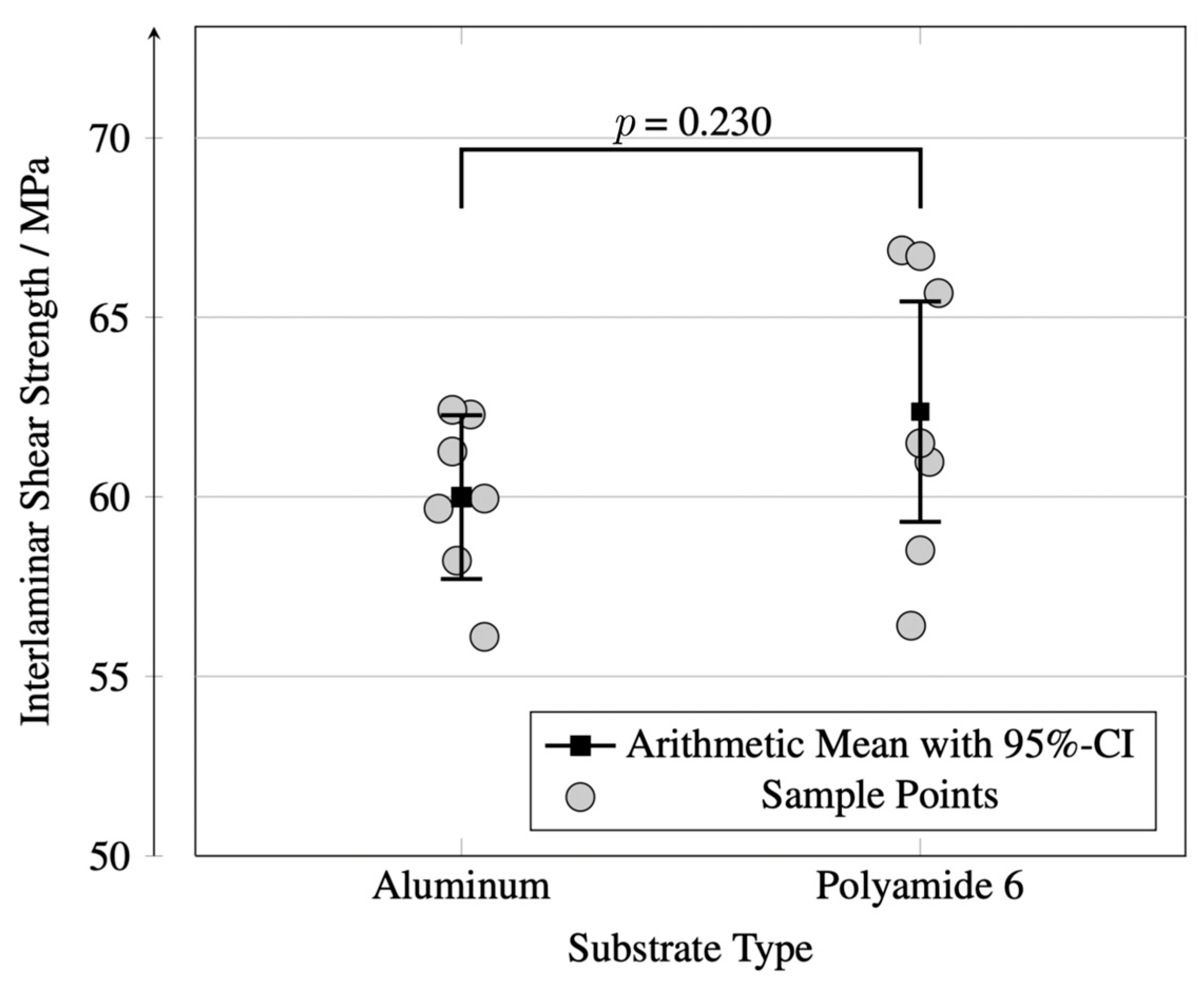
To determine the interlaminar shear strength of laminates, five-point bending tests were conducted according to standard ISO 19927 [
20]. Seven specimens were extracted from each laminate with a dimension of 52 mm × 17 mm × the thickness of the laminate. Specimens were tested using a universal testing machine RetroLine 1475 with a 100 kN load cell, manufactured by the company ZwickRoell GmbH & Co. KG (Ulm, Germany). The testing speed was set to 1 mm·min
−1. The load was measured as a function of the displacement of the crosshead.
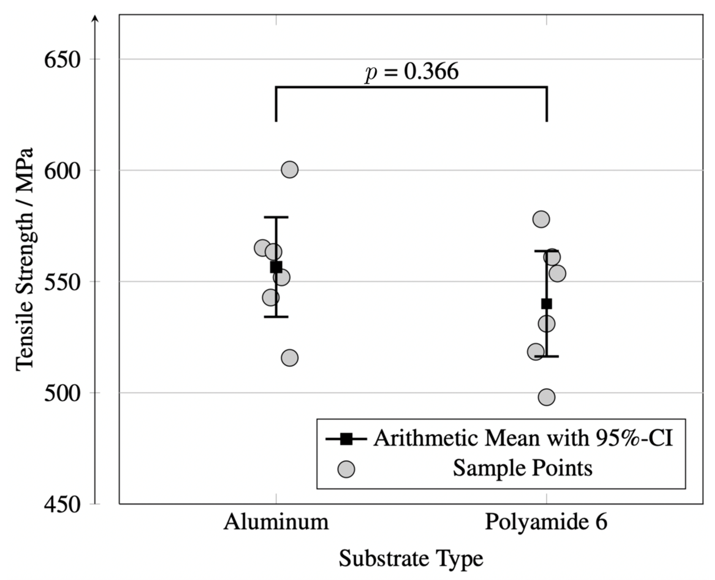
For the determination of the tensile strength of the laminates, specimens were manufactured according to the Airbus test method AITM1-0007 [
21]. Six rectangular specimens with a size of 22 mm × 250 mm were extracted from each laminate. End tabs out of a ±45° glass-fiber-reinforced epoxy material were adhesively bonded to the specimens to equalize the stress distribution during testing. Specimens were tested using a universal testing machine RetroLine 1484 with a 200 kN load cell, manufactured by the company ZwickRoell GmbH & Co. KG (Ulm, Germany), at a speed of 2 mm·min
−1. The load was measured as a function of the crosshead displacement.
Thermal warpage of laminates of the specimens was found to be negligible due to their relatively small dimensions. The testing setups for both tests are depicted in
Figure 3.
2.7. Statistical Analysis
For the comparison of two groups, an unpaired, two-sided t-test was used. p-values of ≤0.05 were considered statistically significant. No multiple testing of samples was performed. The arithmetic mean of sample groups is always displayed with the 95% confidence interval (95%-CI) in figures.
4. Discussion
The objective of this study was to compare the mechanical and morphological characteristics of laminates manufactured on metallic and polymeric substrates. To this end, tensile-strength tests, five-point bending tests, DSC, and microscopy were used. It was found that there is no statistically significant difference in the mechanical properties considered within this study.
However, while DSC analyses revealed significant differences in bulk crystallinity of laminates manufactured on metallic and polymeric substrates, SEM analyses showed no apparent differences in the distribution of surface crystallinity. This discrepancy arises from the fact that DSC evaluates the overall bulk crystallinity within the material, whereas SEM provides a localized, surface-level evaluation of crystalline structures.
While crystallinity directly impacts matrix-dominated mechanical properties, it alone is not a sufficient criterion for drawing conclusions about mechanical properties. For in situ AFP lower mechanical properties were reported for higher crystallinity samples [
23]. Interlaminar shear stress of in situ AFP-manufactured laminates is primarily determined by the consolidation quality. Consolidation quality is determined by intimate contact and healing and is expected to be very similar for the two laminates manufactured with the same AFP process parameter sets and prepreg material. Tensile strength, on the other hand, is a fiber-dominated property and less impacted by crystallinity than other matrix-dominated mechanical properties.
Despite the measured cooling rates during the lay-up being similar for both laminates, the total heat flux through the mold during the lay-up is unknown. It is possible that less energy was directed through the polymeric mold compared to the metallic mold. This is likely the case due to the statistically significant difference in crystallinity of both laminates. The manufacturing setup for this study consisted of a 3 mm thick sheet of PA6 on an aluminum base. A more isolated polymeric substrate may result in a reduced heat flux through the mold’s surface and thus lower the cooling rate of the laminate. This could result in a higher crystallinity and therefore higher strength values. This hypothesis is supported by the findings of Brandt et al. [
8]. Structures 3D printed by large-scale, granular-based systems are prone to high porosity [
24]. This is disadvantageous for their mechanical properties but beneficial to their thermal isolation properties. Since the tests presented in this study were conducted on a casted sheet of PA6, higher crystallinity values (and therefore higher matrix-dominated mechanical properties) can be expected when using actual 3D-printed structures as molds. The recently increasing topic of thermoplastic foams could also further contribute to thermally isolated, thermoplastic molds and increase crystallinity and mechanical properties of composites to a similar extent as toolless approaches [
8,
24]. It should be mentioned that the relatively high values of standard deviations exhibited in this work are common in investigations of AFP composites [
22,
25].
It has been shown that the temperature the tapes are heated during lay-up has a significant effect on the quality of a laminate [
17]. To use PA6 as a substrate for the AFP process requires that the temperature be lowered by more than 10% of the temperature used when using metallic molds. This lowering of the process temperature is necessary to ensure the PA6 is not degrading during the lay-up and to minimize the amount of melted PA6 which could impair the accuracy of the tape placement [
9]. However, this adjustment is only necessary in the first ply. Afterwards, the adjusted parameters do not need to be used. In addition, the tapes of the first ply will be heated multiple times during the lay-up due to the tape-laying head passing over a position multiple times in succeeding plies. This may contribute to the reduction in the effect of the lowered process temperature in the first ply.
One major obstacle in in situ AFP is the accurate placement of the tapes of the first ply in the mold due to the inability of the tapes and the metallic mold to bond to one another. To overcome this challenge, a polymeric film or a composite prepreg is often adhesively bonded to the mold [
7]. The prepreg will function as a substrate for the placement of tapes and as the first ply of a laminate. This method was chosen for this study. Therefore, the first ply of the laminate manufactured in a metallic mold, is not heated by the laser to the same temperature as the tapes and thus is likely to exhibit a higher crystallinity [
22]. However, no variation in the distribution of crystallinity could be observed using microscopy of ion-etched specimens. This may be the case due to the first ply being heated multiple times during the lay-up as it was described above. These findings are consistent with results from Chadwick et al. [
25].
Since the first ply of the lay-up on polymeric substrates was laid onto the mold’s surface at a temperature below the melting temperature of the LM-PAEK but above that of PA6, the surface roughness of the final composite is that of the unprocessed tape [
9]. This is also the case for the use of metallic molds since a sheet of prepreg is used as the first ply which was not heated above the melting temperature of the matrix either. The use of the polymeric mold is, however, more prone to macroscopic surface defects in laminates. Defects can occur due to misplacement of tapes which is more likely on a liquid melt pool of polymer [
9,
26]. The laser and the heated tape both heat the polymeric substrate above its melting temperature. To counteract this potential for defects, the consolidation force was increased and the force in-plane with the tape reduced [
9]. Nevertheless, the displacement of tapes during the lay-up of a few millimeters was occasionally observed during this study. A slower lay-up speed may be beneficial to the accuracy of the placement of tapes. It has been shown that this speed does not affect the properties of the composite part but increases production time and costs [
17].
One of the main advantages of the investigated technology is the direct placement of tapes onto the mold’s surface. Especially with complex mold geometries, preparation of a metallic mold by applying prepreg or polymeric sheets in order to allow the bonding of tapes to the surface increases processing time and costs. This costly and wasteful preparation step is not necessary for the use of polymeric molds due to the ability to bond tapes directly to the mold’s surface.
The main disadvantage of the proposed technology is the inability to heat a polymeric mold to a significant temperature which would be beneficial to the crystallinity and mechanical properties of a laminate. A mold which is heated to a temperature of 200 °C was shown to improve the crystallinity of CF/LM-PAEK laminates on average by 15.7% [
17]. Due to the inability to sufficiently heat a polymeric mold in a way that would increase the crystallinity of composites, the proposed technology is not adaptable for all applications of AFP.
The use of a thermoplastic mold further enhances the contribution of in situ AFP to a circular economy. When used for the manufacturing of thermoset composites, additively manufactured molds experienced a life time of less than 10 manufacturing cycles due to scratches on the surfaces [
27,
28,
29]. After a thermoplastic mold exceeds its life time, the mold can be recycled into granulate and can be used for the printing of new molds. A main concern for the usage of recycled thermoplastics for aerospace use is a reduction in mechanical properties [
30]. Since molds do not need to fulfill the same requirements as aerospace-grade structures, recycled thermoplastics are most likely suitable for mold manufacturing. Furthermore, the comparatively short life time of additively manufactured molds exhibited in other studies could be longer when used for the manufacturing of thermoplastic composites. Due to the mold’s surface being heated above its melting temperature during the lay-up, potential scratches on a mold do not affect the surface of the composite part.
It has been suggested that the use of thermoplastic molds for the manufacturing of thermoset composites reduces tooling costs by 50% [
31]. Additively manufactured molds for the production of thermoplastic composites are most likely to reduce the costs of tooling even further. This is mainly due to lower requirements for the surface quality and air-tightness of the mold. The underlying technology is based on the mold’s surface being melted during the lay-up of the composite; thus, extensive machining of the surface is not necessary. In addition, in situ AFP does not require post-consolidation of a part and therefore the mold does not need to be air-tight, which would be necessary for vacuum bagging. It remains difficult to estimate the cost of tooling based on a chosen technology, since various factors (e.g., size, complexity, and material) influence this value. However, in
Figure 9 results from multiple studies and the presented results of this study were summarized comparing the possible crystallinity of composites of different tooling technologies with regard to the cost of the tooling. The crystallinity is used as an indicator of the mechanical and chemical performance of parts. This figure clearly illustrates that 3D-printed molds are one method to reduce production costs while increasing product performance. It should be mentioned that heated, metallic molds are more expensive than non-heated molds due to additional equipment being necessary for the heating of those. However, no explicit data has been published on the cost of heated molds and thus no specific upper limit or lower limit of mold costs is depicted in
Figure 9.
An additional, considerable advantage of 3D-printed molds compared to metallic molds is the significant reduction in the weight of the molds. Especially complex molds may need to be moved during the lay-up of a part due to geometric constraints. Light molds facilitate the usage of robotic manipulators to move a mold during the manufacturing of a composite part. In manufacturing cells with a limited allowed load, molds of greater size can be used. Further, the integration and removal of a mold from a manufacturing cell are also manageable with fewer personnel and equipment compared to metallic molds.
This study focused on the usage of a mold material polymer with a lower melting temperature than that of the composites’ matrix. The results are however most likely adoptable for high-performance polymer molds [
33]. Future work will focus on the impact of thermoplastic tool surface roughness, comparing 3D-printed and cast tools, and reusability and potential degradation of polymer molds.
5. Conclusions
This study presents the experimental investigation of differences in the mechanical properties of composite laminates manufactured on polymeric and metallic molds. The goal of the study was to determine the suitability of 3D-printed polymeric molds for in situ automated fiber placement. It was found that composites manufactured on polymeric substrates do not have a statistically significant change in mechanical properties compared to composites manufactured in traditional, metallic molds. However, a significant difference in crystallinity was found.
Although it has been demonstrated that polymeric molds can be superior to the use of metallic molds in multiple aspects, the accuracy of parts over the life time of a polymeric mold, the effect of defects in the mold’s surface, and the life time of a 3D-printed mold remain unknown and should be investigated in future studies.
It can be concluded that laminates can be manufactured on polymeric molds with comparable properties to those manufactured on metallic molds. Those properties include tensile strength, interlaminar shear strength, surface roughness, and crystallinity. With an optimized design of the mold, which reduces the heat flux through the mold, it may be possible to achieve higher mechanical strength values. The presented results showcase the ecological and economic advantages of combining 3D printing with automated fiber placement.


 ,
, 


