Abstract
Bioinspired nanocomposites aim to mimic the structure of natural materials. These materials exhibit excellent mechanical properties such as high strength, toughness, and stiffness. Using modeling and simulation, we can gain insight into the underlying mechanisms that control the properties of these materials, study the impact of various parameters on their performance, and design new materials with high performance. This study investigates a bone-inspired nanocomposite that consists of two subunits: Subunit-A (Mineralized Collagen Fibril) and Subunit-B (Extrafibrillar Matrix). Subunit-B provides the composite with stiffness before yielding. After yielding, Subunit-A stretches to accommodate the deformation up to the final failure. The adhesive material in the interface plays an important role in this nanocomposite’s failure. The composite’s toughness is enhanced by multiple mechanisms: diffuse damage in Subunit-B, strain relaxation around crack tips through horizontal interface delamination between the subunits, and the crack bridging role of Subunit-A. This study provides insight into the mechanical behavior of bone-inspired nanocomposites under tensile loading conditions, highlighting the importance of the adhesive phase in optimizing the material performance in various applications.
1. Introduction
In nature, there are many examples of tough, strong, lightweight, and multifunctional structures, which can be an inspiration for the design of high performance materials, such as nacre and bone [1,2,3,4,5]. Bone is a complex biological material that serves as the primary structural support for the human body [6]. It is a composite material consisting of mineralized collagen fibrils and non-collagenous proteins, and its mechanical properties are governed by its hierarchical structure spanning from the macro- down to nano-scale [7,8,9,10]. This hierarchical structure is essential for the unique combination of stiffness, strength, and toughness that bones exhibit. Understanding the hierarchical structure of bone is critical to the development of biomimetic materials that can mimic the mechanical properties of bone. By mimicking the structure of bone, it is possible to design new materials that can be used in a wide range of applications in industry [11,12,13,14,15,16,17]. The hierarchical structure of bone is shown in Figure 1. At the macroscopic scale, bones have a well-defined shape and structure, with a compact portion called cortical bone and spongy portion called cancellous bone [18,19,20]. At the mesoscale, the basic building blocks of cortical bone are osteons, also known as Haversian systems, which are the basic functional unit of compact bone tissue and consist of concentric layers of bone tissue arranged around a central canal. These concentric layers are known as lamellae. At the nanoscale, each lamella is composed of Mineralized Collagen Fibril (MCF) and Extrafibrillar Matrix (EFM) [21,22,23,24]. The MCF is a complex structure composed of collagen and hard hydroxyapatite (HA) mineral platelets. The EFM consists of hard HA crystals bonded through a thin layer of Non-Collagenous Proteins (NCPs), which can be considered as a tough bioadhesive [25]. The layer of NCPs consists of Osteocalcin (OC), Osteopontin (OPN), HO, and Proteoglycans (PGs). The MCF and EFM make up the building blocks of bone tissue, providing it with the unique combination of strength, toughness, and resilience required for its many functions in the body. Understanding the composition and structure of lamellae is crucial to study the mechanics and properties of bone.
Figure 1.
Hierarchical structure of bone spanning from the macro- down to nano-scale [26,27,28].
Bioinspired nanocomposites are a class of materials that aim to mimic the structure and properties of natural materials [29,30,31]. These materials have been found to exhibit excellent mechanical properties, including high strength, toughness, and stiffness. Due to their unique properties and potential applications, biomimetic materials have attracted extensive attention in recent years. Computational modeling and simulation techniques are critical tools in the design and development of these materials. The interfaces in these materials play a significant role in determining their material properties. The cohesive zone model (CZM) is widely used to describe and analyze the damage mode of material interface during the failure process [32,33,34,35,36,37]. The CZM has proven to be highly effective in capturing the intricate interactions between different material phases and predicting the initiation and propagation of cracks, debonding, and other failure mechanisms. Using modeling and simulation, we can gain insight into the underlying mechanisms that control the properties of bioinspired nanocomposites, study the impact of various parameters on the performance, and design new materials with higher performance, leading to new and exciting applications in many fields.
2. Computational Model
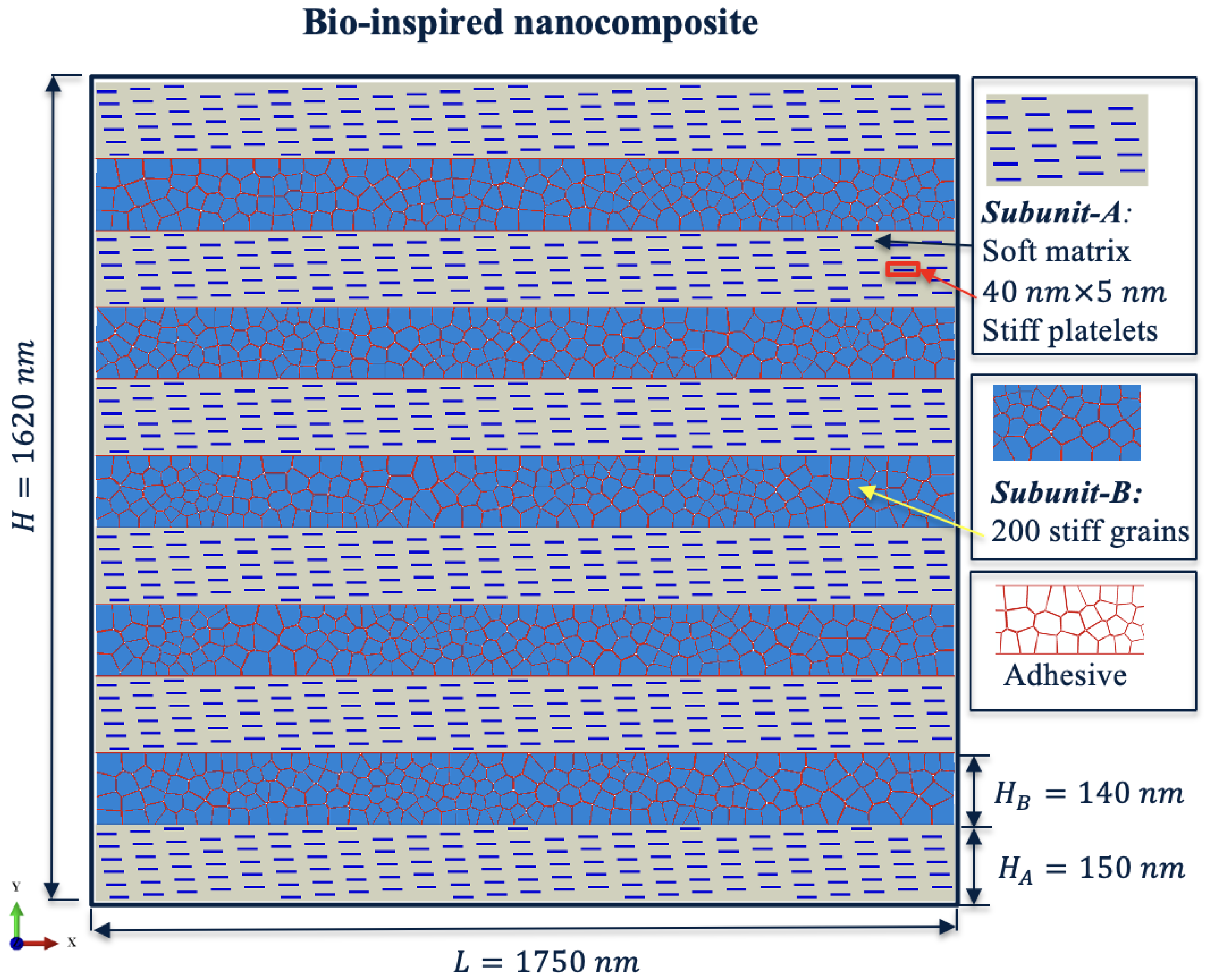
2.1. Geometric Model
In this study, we develop a two-dimensional (2D) computational model of bone-inspired nanocomposite material. The structural model of the lamella-like nanocomposite consists of two different subunits (Figure 2), Subunit-A (MCF) and Subunit-B (EFM), which are aligned in the horizontal direction and connected by a thin layer of glue-like interface material. Subunit-A is a soft matrix that contains stiff plates with a size of , while Subunit-B is composed of 200 randomly distributed stiff grains via Voronoi tessellation and connected by a glue-like interface material. According to the structural description of bone tissue from previous studies [21,22,23,24], the MCF in the bone structure is modeled as a periodic arrangement. The Subunit-A mimics the MCF in bone, which exhibits a periodic arrangement. Subunit-B resembles the EFM of bone tissue, which is modeled as a random aggregate of polycrystals of a stiff material (similar to hydroxyapatite grains) bounded through a thin adhesive substance. The height of Subunit-A is 150 nm and the height of Subunit-B is 140 nm, while both subunits have the same length of 1750 nm. The total dimension of the composite structure is .
Figure 2.
Structural model of the lamella-like nanocomposite.
The structural model of the proposed nanocomposite is shown in Figure 2. The composite material is studied under uniaxial tensile loading in the X-axis direction. The right and left edges of the nanocomposite were subjected to horizontal tensile displacement boundary conditions, while being constrained for vertical movement. Throughout the loading step, the total kinetic energy of the model was monitored and compared with respect to the total strain energy of the model. The ratio was less than 5%, ensuring an acceptable state of a quasi-static loading condition. The model verification and a convergence study on nanocomposite size and mesh size were conducted in our previous studies in composite materials with a similar structure [16,17,24,38].
2.2. Material Property
The bone-inspired nanocomposite material consists of a soft matrix, stiff plates, stiff grains, and adhesive. The volume fraction of each component can be found in Table 1. The material parameters used for the modeling matrix, platelets, and grains are listed in Table 2 and used to accurately simulate the mechanical properties and behavior of the material under mechanical loading conditions. Polymethyl methacrylate (PMMA) is by far the most frequently used bone substitute material for vertebroplasty [39]. The soft matrix properties were set to the following: Young’s modulus GPa, Poission ratio , and failure strain [40]. According to the material properties of hard HA mineral platelet crystals reported in the literature [41,42], the material parameters of stiff plates and stiff grains were set to the following: Young’s modulus GPa and Poission ratio . By tuning the relevant material parameters, the computational model is able to replicate the mechanical properties and behavior of the bone-inspired nanocomposite materials. The detailed characterization of the material properties and the accurate representation of the different components in the model can lead to a better understanding of the performance of the bone-inspired nanocomposite material and how it can be optimized for specific applications.
Table 1.
Volume fraction of different constituents of the nanocomposite [16].
Table 2.
Material parameters used for modeling matrix, platelets, and grains in base model [40,41,42].
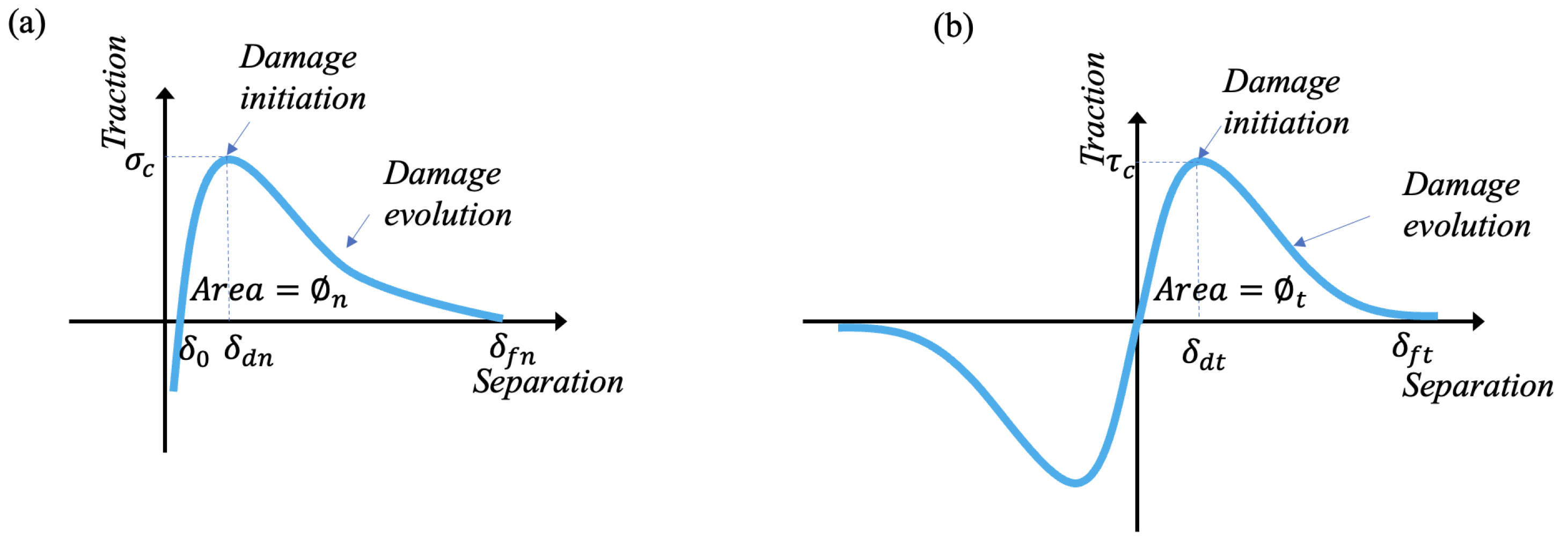
2.3. Cohesive Zone Model for Material Interface Modeling
In this study, a finite element (FE) model of the bone-inspired nanocomposite was created with 142,000 elements. Those elements are comprised of 126,000 linear triangle elements, 5000 linear quadrilateral elements, and 11,000 user-defined linear cohesive elements. The geometry and FE model were created by ABAQUS software. A generalized cohesive zone model was implemented in a VUEL subroutine (user-defined element) in the ABAQUS package. A central difference dynamic explicit solution scheme was chosen over a Newton–Raphson implicit scheme mainly because of its capability to ensure a converged solution, especially when material softening occurs in the system (in our case, at cohesive elements). The increment time step was selected as s, and mass scaling (adjusting the density of elements) was activated during the step to ensure that the minimum stable time increment of all elements was greater than the specified . The average element size was found to be 7 nm from mesh sensitivity analysis. The finite element mesh could capture the complex microstructure of the nanocomposite material, including its different components and their interactions. To provide a clear understanding of the mesh structure, a zoomed-in view of the finite element mesh is presented in Figure 3. Using a large number of elements and a detailed mesh structure in the finite element model allowed us to make sure of the high-level accuracy of the simulation results. This in turn provided a more comprehensive understanding of the mechanical behavior of the bone-inspired nanocomposite material.
Figure 3.
Zoom in view of mesh.
To describe the adhesive material deformation behavior, a cohesive zone model (CZM) was proposed to mimic various interface behaviors. Figure 4 shows the traction–separation relations in normal and tangential directions, which were used to govern the adhesive material behaviors.
Figure 4.
Traction–separation relations used to describe adhesive material behaviors: (a) normal direction; (b) tangential direction.
The cohesive zone model is widely used to study the composite material failure process [38,43,44,45,46,47,48,49,50,51]. The adhesive tractions in the surface normal and tangential direction take the following form:
where and are the cohesive strength in the normal and tangential directions, respectively, and and are critical separation. and are normal and tangential final failure separation. is the equilibrium position and . The shape parameters () are introduced to describe different adhesive material behaviors (e.g., brittle, ductile, elastic–perfectly plastic, rubber-like behavior, etc). The variables and represent normal and tangential separation, respectively. The main advantage of the model is that one can independently control the interface properties (e.g., stiffness, strength, toughness). The stiffness (, ) of the adhesive at the equilibrium position is defined as
The adhesive toughness (,) can be determined from the integrated area under the traction–separation curve. They can be defined as
The adhesive material behaviors were governed by the cohesive zone model. The cohesive zone parameters can be obtained from experimental measurements (e.g., double cantilever beam), molecular dynamics, or other numerical simulations [52]. The cohesive zone parameters used in our model were estimated based on the experimental data or numerical simulation results reported in the literature [41,53,54,55]. Cohesive zone parameters used for modeling adhesive material in the computational model are listed in Table 3.
Table 3.
Cohesive zone parameters used for modeling adhesive material in the computational model [41,53,54,55].
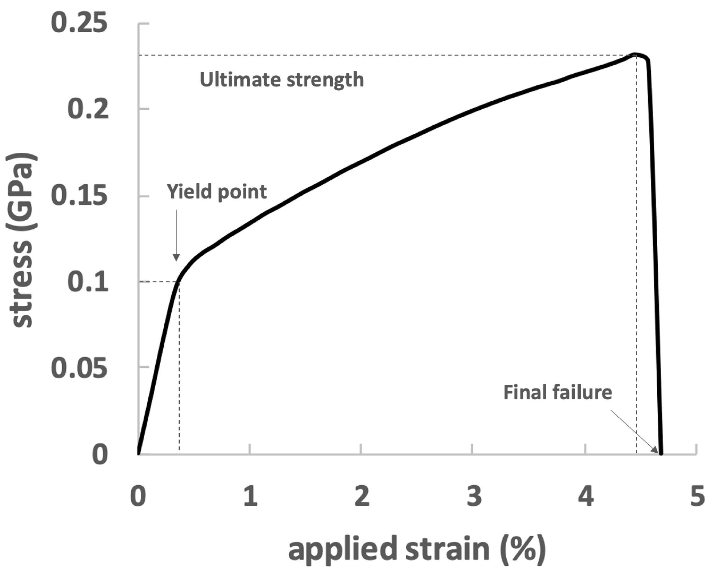
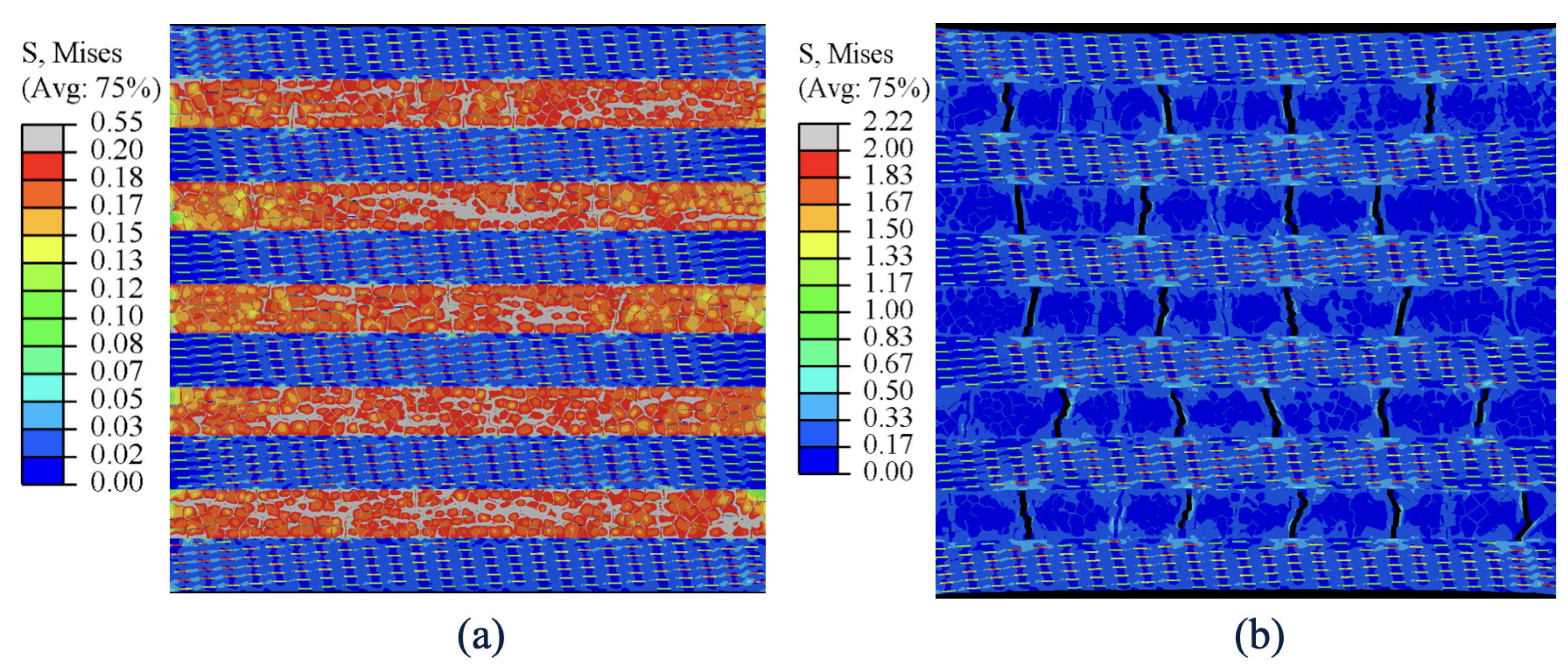
3. Results and Discussion
The average stress versus applied strain for the bone-inspired nanocomposite is plotted in Figure 5. The initial stiffness of the composite is 27.5 GPa and yield stress was found to be 100 MPa. After yielding, the bulk stress proceeded with a gradual increase with a much lower slope and reached the ultimate strength, which may indicate a strain hardening process. The post-yield stiffness is 3.13 GPa, and the ultimate stress is 232 MPa. The failure strain is 4.7%.
Figure 5.
Stress–strain relationship of the bone-inspired nanocomposite.
Before the yielding point, both subunits resist the applied strain in a cooperative manner, but Subunit-B is the primary load carrying unit and is stressed more than Subunit-A. Figure 6a also shows that Subunit-Bs have the highest tensile stress regions of the nanocomposite in the pre-yield stage. In the post-yield stage of deformation, Subunit-A begins to increasingly carry a greater portion of the load and contributes to the bulk mechanical response of the composite.
Figure 6.
Von-Mises stress contour (a) at yield strain showing significant contribution of Subunit-B at pre-yield loading regime and (b) at maximum applied strain showing high stresses (near theoretical strength) in platelets of Subunit-A.
To investigate the mechanical performance of the nanocomposite, diffuse damage and crack evolution are two important factors. The nanocomposite damage showed in the figure is based on ductile damage modelling (DUCTCRT). FE simulations captured the distribution and evolution of damage in the model (Figure 7). The red color represents adhesive regions that have reached the critical cohesive strength (). Before yielding, the averaged stress in Subunit-B was found to be higher than that in Subunit-A. Once the stress in Subunit-B reached the critical strength of the adhesive phase, yielding ensued in the bulk stress–strain curve. The adhesive continued softening and experienced failure until the bulk stress reached its ultimate strength. Thereafter, stress quickly dropped to zero.
Figure 7.
Diffuse damage and crack initiation in bone-inspired nanocomposite for applied strain from 0 to 3.5%.
The crack propagation pattern in the post-yield stage is displayed in Figure 8. When reached 3.5%, many interface regions in Subunit-B were under softening. In this stage, Subunit-B was the major load-bearing component, which is the reason why it was particularly vulnerable to damage. When reached 4%, damage began in Subunit-B and created many cracks to dissipate energy. As the stress continued to increase in the soft matrix, it eventually reached its critical strength, and the cracks began to propagate into the soft matrix, leading to the formation of the final failure crack. The final failure process is observed at a range of applied strains between 4.2% and 4.5%.
Figure 8.
Diffuse damage and crack propagation in bone-inspired nanocomposite for applied strain from 3.5% to 4.5%.
Through the analysis of the fracture pattern in the nanocomposite, we found that the cracks were initiated at the adhesive perpendicular to the loading direction when the model was loaded in tension (Figure 7 and Figure 8). When the damage at the adhesive began to be initiated, the stress was released within the damaged cohesive zone region. As the loading kept increasing, cracks nucleated and coalesced and finally traveled vertically, passing through the nanocomposite (Figure 8). The interface sliding (Mode II) occurred along the grain boundaries in Subunit-B. It seems that there is a tendency for crack initiation, nucleation and coalescence mainly in mode I.
The stress–strain curve for the bulk nanocomposite and its two individual subunits A and B is plotted in Figure 9. Upon comparison of the three stress–strain curves, it is observed that at the initial stage of loading, Subunit-B carried the majority of the load and provided a high stiffness in bulk. Once the average stress in Subunit-B reached its critical strength, yielding occurred in the bulk stress–strain curve. During the post-yield deformation, the bulk stress continued to increase with a much lower slope. Once diffuse damage and cracks happened in Subunit-B, Subunit-A was observed to carry a load.
Figure 9.
Stress–strain curve for the bone-inspired composite and its two subunits A and B.
This analysis shows the shift in load-bearing responsibilities in the composite. Subunit-B made a significant contribution in the pre-yield loading regime. It is clear that high stresses were present in Subunit-B. As the loading progressed, Subunit-B started to experience damage, and cracks grew. The soft matrix in Subunit-A began softening, and the stiff platelets in Subunit-A then experienced high stresses. This shift in load-bearing responsibilities highlights the importance of understanding the behavior of individual subunits in a composite material and their contributions to the overall behavior of the composite.
To investigate the stiff plate effect, Figure 10 shows the strain contour at maximum applied strain. It is notable that the high strain concentration () around the crack tips eventually initiated the failure of the soft matrix. An inhomogeneous stress distribution in Subunit-A created a pattern of low and high strain bands. Specifically, the low strain band had stiff plates, which experienced high level stress compared to the high strain band. The low strain band effectively absorbed energy and slowed down the material failure.
Figure 10.
Strain contour at maximum applied strain.
To study the cohesive zone parameter effect on the composite, we designed a case to study the material response under different adhesive strengths. Figure 11 shows different strain–stress curves under different adhesive strengths. The snapshots were captured at the final failure stage. L.1 shows the composite deformation under Mpa, L.2 shows the composite deformation under Mpa, and L.3 shows the composite deformation under Mpa. The parametric study revealed that the behavior of the composite material was strongly influenced by the strength of the interface. Specifically, the results indicate that a weaker interface in the composite led to more crack formation, increasing the composite’s ultimate stress and toughness. One might expect a stronger interface to result in a stronger composite material; however, a strong interface can also cause stress concentrations, which can lead to the premature failure of the material. In contrast, a weaker interface allows for more crack formation and redistribution of stress, which can increase the overall toughness of the bone-inspired nanocomposite.
Figure 11.
The role of adhesive strength on the bone-inspired material response.
It is important to note that the behavior of bone-inspired composite materials is complex and can be influenced by a variety of factors, including composition, processing conditions, and external loads. Nevertheless, the findings from this study provide valuable insights into the role of adhesive parameters on the behavior of composite materials. These insights can inform the design and optimization of composite structures for various applications.
4. Conclusions
This bone-inspired nanocomposite is made up of two subunits. Before yielding, Subunit-B, which comprises 86% of the total stiff phase content, provides the composite with stiffness. After yielding, Subunit-A stretches to accommodate the composite deformation up to 5%. Stiff platelets in Subunit-A also contribute to the post-yield stiffness of the composite. The strength of the adhesive material plays a significant role in the yield stress of the composite. Additionally, the failure strain of the soft matrix is a prime contributor to the ultimate stress of the composite. The toughness of the composite material is enhanced by several mechanisms:
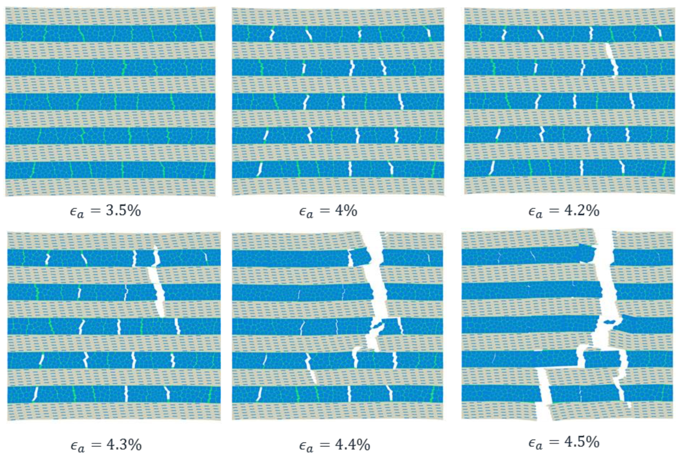
- Energy dissipation through diffuse damage in Subunit-B,
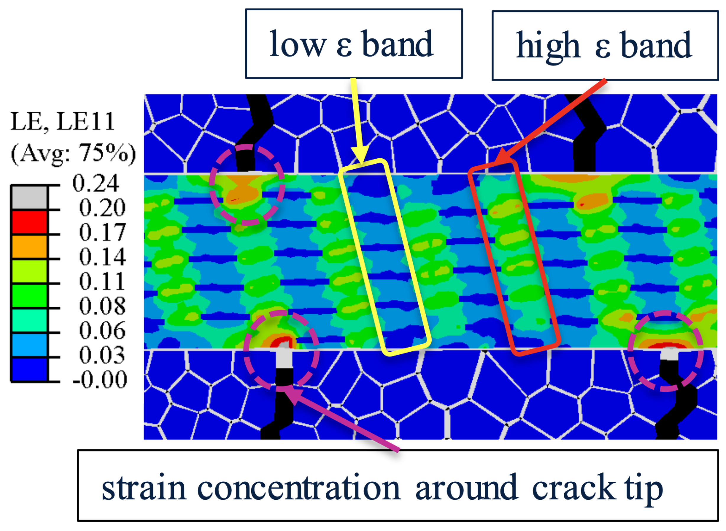
- Strain relaxation around crack tips through horizontal interface delamination between the subunits, and
- The crack bridging role of Subunit-A.
The failure mechanism of the composite material is a multi-stage process. The final failure begins with damage nucleation in Subunit-A from the tips of the stiff platelets. This leads to the formation of a crack in Subunit-A. As the crack grows, it can coalesce with other cracks in the subunits and eventually form a crack across the entire composite. This can ultimately result in the failure of the material. Overall, this study provides insight into the mechanical behavior of the bone-inspired nanocomposite material under tensile loading conditions. The results highlight the importance of the different components and their interactions in determining the overall mechanical performance of the material. Understanding the stiffness, strengthening, toughening, and failure mechanisms of composite materials is crucial for their design and optimization for various applications.
Author Contributions
Conceptualization, X.Z.; methodology, X.Z.; software, X.Y. and M.M.-G.; validation, X.Y.; formal analysis, X.Y. and M.M.-G.; investigation, X.Y.; resources, X.Z.; data curation, X.Y. and M.M.-G.; writing—original draft preparation, X.Y.; writing—review and editing, X.Z. and M.M.-G.; visualization, X.Y. and M.M.-G.; supervision, X.Z.; project administration, X.Z.; funding acquisition, X.Z. All authors have read and agreed to the published version of the manuscript.
Funding
This research was funded by a grant from the University of Texas at San Antonio, Office of the Vice President for Research.
Institutional Review Board Statement
Not applicable.
Informed Consent Statement
Not applicable.
Data Availability Statement
All data generated or analyzed during this study are included in this published article.
Acknowledgments
Valuable discussions with Xiaodu Wang at Mechanical Engineering of UTSA are gratefully acknowledged.
Conflicts of Interest
The authors declare no conflict of interest.
Sample Availability
Not applicable.
Abbreviations
The following abbreviations are used in this manuscript:
| 2D | Two-dimensional |
| CZM | Cohesive zone model |
| EFM | Extrafibrillar matrix |
| FE | Finite element |
| HA | Hydroxyapatite |
| MCF | Mineralized collagen fibril |
| NCP | Non-collagenous proteins |
| OC | Osteocalcin |
| OPN | Osteopontin |
| PGs | Proteoglycans |
References
- Amorim, L.; Santos, A.; Nunes, J.P.; Viana, J.C. Bioinspired approaches for toughening of fibre reinforced polymer composites. Mater. Des. 2021, 199, 109336. [Google Scholar] [CrossRef]
- Begley, M.R.; Philips, N.R.; Compton, B.G.; Wilbrink, D.V.; Ritchie, R.O.; Utz, M. Micromechanical models to guide the development of synthetic ‘brick and mortar’ composites. J. Mech. Phys. Solids 2012, 60, 1545–1560. [Google Scholar] [CrossRef]
- Huang, W.; Restrepo, D.; Jung, J.Y.; Su, F.Y.; Liu, Z.; Ritchie, R.O.; McKittrick, J.; Zavattieri, P.; Kisailus, D. Multiscale toughening mechanisms in biological materials and bioinspired designs. Adv. Mater. 2019, 31, 1901561. [Google Scholar] [CrossRef] [PubMed]
- Launey, M.E.; Ritchie, R.O. On the Fracture Toughness of Advanced Materials. Adv. Mater. 2009, 21, 2103–2110. [Google Scholar] [CrossRef]
- Ritchie, R.O. The conflicts between strength and toughness. Nat. Mater. 2011, 10, 817–822. [Google Scholar] [CrossRef]
- Lefèvre, E.; Farlay, D.; Bala, Y.; Subtil, F.; Wolfram, U.; Rizzo, S.; Baron, C.; Zysset, P.; Pithioux, M.; Follet, H. Compositional and mechanical properties of growing cortical bone tissue: A study of the human fibula. Sci. Rep. 2019, 9, 17629. [Google Scholar] [CrossRef] [PubMed]
- Dunlop, J.W.C.; Fratzl, P. Biological Composites. Annu. Rev. Mater. Res. 2010, 40, 1–24. [Google Scholar] [CrossRef]
- Fantner, G.E.; Hassenkam, T.; Kindt, J.H.; Weaver, J.C.; Birkedal, H.; Pechenik, L.; Cutroni, J.A.; Cidade, G.A.; Stucky, G.D.; Morse, D.E.; et al. Sacrificial bonds and hidden length dissipate energy as mineralized fibrils separate during bone fracture. Nat. Mater. 2005, 4, 612–616. [Google Scholar] [CrossRef]
- Giorgio, I.; Spagnuolo, M.; Andreaus, U.; Scerrato, D.; Bersani, A.M. In-depth gaze at the astonishing mechanical behavior of bone: A review for designing bio-inspired hierarchical metamaterials. Math. Mech. Solids 2020, 26, 1074–1103. [Google Scholar] [CrossRef]
- Hamed, E.; Lee, Y.; Jasiuk, I. Multiscale modeling of elastic properties of cortical bone. Acta Mech. 2010, 213, 131–154. [Google Scholar] [CrossRef]
- Koons, G.L.; Diba, M.; Mikos, A.G. Materials design for bone-tissue engineering. Nat. Rev. Mater. 2020, 5, 584–603. [Google Scholar] [CrossRef]
- Libonati, F.; Gu, G.X.; Qin, Z.; Vergani, L.; Buehler, M.J. Bone-Inspired Materials by Design: Toughness Amplification Observed Using 3D Printing and Testing. Adv. Eng. Mater. 2016, 18, 1354–1363. [Google Scholar] [CrossRef]
- Meyers, M.A.; Chen, P.Y.; Lin, A.Y.M.; Seki, Y. Biological materials: Structure and mechanical properties. Prog. Mater. Sci. 2008, 53, 1–206. [Google Scholar] [CrossRef]
- Robles-Linares, J.A.; Ramírez-Cedillo, E.; Siller, H.R.; Rodríguez, C.A.; Martínez-López, J.I. Parametric modeling of biomimetic cortical bone microstructure for additive manufacturing. Materials 2019, 12, 913. [Google Scholar] [CrossRef] [PubMed]
- Zhang, P.; Heyne, M.A.; To, A.C. Biomimetic staggered composites with highly enhanced energy dissipation: Modeling, 3D printing, and testing. J. Mech. Phys. Solids 2015, 83, 285–300. [Google Scholar] [CrossRef]
- Maghsoudi-Ganjeh, M.; Samuel, J.; Ahsan, A.S.; Wang, X.; Zeng, X. Intrafibrillar mineralization deficiency and osteogenesis imperfecta mouse bone fragility. J. Mech. Behav. Biomed. Mater. 2021, 117, 104377. [Google Scholar] [CrossRef] [PubMed]
- Maghsoudi-Ganjeh, M.; Wang, X.; Zeng, X. Computational investigation of the effect of water on the nanomechanical behavior of bone. J. Mech. Behav. Biomed. Mater. 2020, 101, 103454. [Google Scholar] [CrossRef]
- Olszta, M.J.; Cheng, X.; Jee, S.S.; Kumar, R.; Kim, Y.Y.; Kaufman, M.J.; Douglas, E.P.; Gower, L.B. Bone structure and formation: A new perspective. Mater. Sci. Eng. Rep. 2007, 58, 77–116. [Google Scholar] [CrossRef]
- Reznikov, N.; Shahar, R.; Weiner, S. Bone hierarchical structure in three dimensions. Acta Biomater. 2014, 10, 3815–3826. [Google Scholar] [CrossRef]
- Zhu, G.; Zhang, T.; Chen, M.; Yao, K.; Huang, X.; Zhang, B.; Li, Y.; Liu, J.; Wang, Y.; Zhao, Z. Bone physiological microenvironment and healing mechanism: Basis for future bone-tissue engineering scaffolds. Bioact. Mater. 2021, 6, 4110–4140. [Google Scholar] [CrossRef]
- Launey, M.E.; Buehler, M.J.; Ritchie, R.O. On the Mechanistic Origins of Toughness in Bone. Annu. Rev. Mater. Res. 2010, 40, 25–53. [Google Scholar] [CrossRef]
- Pylypenko, O.; Ignatev, A.; Lundmark, R.; Rasmuson, E.; Carlsson, S.R.; Rak, A. A combinatorial approach to crystallization of PX–BAR unit of the human Sorting Nexin 9. J. Struct. Biol. 2008, 162, 356–360. [Google Scholar] [CrossRef] [PubMed]
- Volkmann, N.; Martásek, P.; Roman, L.J.; Xu, X.P.; Page, C.; Swift, M.; Hanein, D.; Masters, B.S. Holoenzyme structures of endothelial nitric oxide synthase–An allosteric role for calmodulin in pivoting the FMN domain for electron transfer. J. Struct. Biol. 2014, 188, 46–54. [Google Scholar] [CrossRef] [PubMed]
- Maghsoudi-Ganjeh, M.; Wang, X.; Zeng, X. Nanomechanics and ultrastructure of bone: A review. Comput. Model. Eng. Sci. 2020, 125, 1–32. [Google Scholar]
- Lin, L.; Samuel, J.; Zeng, X.; Wang, X. Contribution of extrafibrillar matrix to the mechanical behavior of bone using a novel cohesive finite element model. J. Mech. Behav. Biomed. Mater. 2017, 65, 224–235. [Google Scholar] [CrossRef]
- Zhu, L.; Luo, D.; Liu, Y. Effect of the nano/microscale structure of biomaterial scaffolds on bone regeneration. Int. J. Oral Sci. 2020, 12, 6. [Google Scholar] [CrossRef]
- Rho, J.Y.; Kuhn-Spearing, L.; Zioupos, P. Mechanical properties and the hierarchical structure of bone. Med. Eng. Phys. 1998, 20, 92–102. [Google Scholar] [CrossRef]
- Maghsoudi-Ganjeh, M.; Lin, L.; Wang, X.; Zeng, X. Bioinspired design of hybrid composite materials. Int. J. Smart Nano Mater. 2019, 10, 90–105. [Google Scholar] [CrossRef]
- Liu, Z.; Meyers, M.A.; Zhang, Z.; Ritchie, R.O. Functional gradients and heterogeneities in biological materials: Design principles, functions, and bioinspired applications. Prog. Mater. Sci. 2017, 88, 467–498. [Google Scholar] [CrossRef]
- Tan, G.; Yu, Q.; Liu, Z.; Wang, X.; Zhang, M.; Liu, Y.; Zhang, Z.; Ritchie, R.O. Compression fatigue properties and damage mechanisms of a bioinspired nacre-like ceramic-polymer composite. Scr. Mater. 2021, 203, 114089. [Google Scholar] [CrossRef]
- Wegst, U.G.; Bai, H.; Saiz, E.; Tomsia, A.P.; Ritchie, R.O. Bioinspired structural materials. Nat. Mater. 2015, 14, 23–36. [Google Scholar] [CrossRef]
- Ghabezi, P.; Farahani, M. Effects of nanoparticles on nanocomposites mode I and II fracture: A critical review. Int. J. Adhes. Adhes. 2018, 3, 391–411. [Google Scholar]
- Huang, M.; Yang, H.; Zou, C.; Zang, M.; Chen, S. Effects of Interlaminar Failure on the Scratch Damage of Automotive Coatings: Cohesive Zone Modeling. Polymers 2023, 15, 737. [Google Scholar] [CrossRef]
- Ghabezi, P.; Farahani, M. Trapezoidal traction–separation laws in mode II fracture in nano-composite and nano-adhesive joints. J. Reinf. Plast. Compos. 2018, 37, 780–794. [Google Scholar] [CrossRef]
- Al-Saawani, M.A.; Al-Negheimish, A.I.; El-Sayed, A.K.; Alhozaimy, A.M. Finite element modeling of debonding failures in FRP-strengthened concrete beams using cohesive zone model. Polymers 2022, 14, 1889. [Google Scholar] [CrossRef]
- Biswakarma, J.J.; Cruz, D.A.; Bain, E.D.; Dennis, J.M.; Andzelm, J.W.; Lustig, S.R. Modeling Brittle Fractures in Epoxy Nanocomposites Using Extended Finite Element and Cohesive Zone Surface Methods. Polymers 2021, 13, 3387. [Google Scholar] [CrossRef] [PubMed]
- Ghabezi, P.; Farahani, M. A cohesive model with a multi-stage softening behavior to predict fracture in nano composite joints. Eng. Fract. Mech. 2019, 219, 106611. [Google Scholar] [CrossRef]
- Maghsoudi-Ganjeh, M.; Lin, L.; Wang, X.; Zeng, X. Computational investigation of ultrastructural behavior of bone using a cohesive finite element approach. Biomech. Model. Mechanobiol. 2019, 18, 463–478. [Google Scholar] [CrossRef] [PubMed]
- Boger, A.; Bisig, A.; Bohner, M.; Heini, P.; Schneider, E. Variation of the mechanical properties of PMMA to suit osteoporotic cancellous bone. J. Biomater. Sci. Polym. Ed. 2008, 19, 1125–1142. [Google Scholar] [CrossRef] [PubMed]
- Ishiyama, C.; Higo, Y. Effects of humidity on Young’s modulus in poly (methyl methacrylate). J. Polym. Sci. Part Polym. Phys. 2002, 40, 460–465. [Google Scholar] [CrossRef]
- Zhang, N.; Chen, Y. Nanoscale plastic deformation mechanism in single crystal aragonite. J. Mater. Sci. 2013, 48, 785–796. [Google Scholar] [CrossRef]
- Hrabánková, I.; Frỳda, J.; Šepitka, J.; Sasaki, T.; Frỳdová, B.; Lukeš, J. Mechanical properties of deep-sea molluscan shell. Comput. Methods Biomech. Biomed. Eng. 2013, 16, 287–289. [Google Scholar] [CrossRef] [PubMed]
- Lin, L.; Wang, X.; Zeng, X. Geometrical modeling of cell division and cell remodeling based on Voronoi tessellation method. Cmes: Comput. Model. Eng. Sci. 2014, 98, 203–220. [Google Scholar]
- Lin, L.; Wang, X.; Zeng, X. The role of cohesive zone properties on intergranular to transgranular fracture transition in polycrystalline solids. Int. J. Damage Mech. 2017, 26, 379–394. [Google Scholar] [CrossRef]
- Lin, L.; Wang, X.; Zeng, X. Computational modeling of interfacial behaviors in nanocomposite materials. Int. J. Solids Struct. 2017, 115, 43–52. [Google Scholar] [CrossRef]
- Lin, L.; Wang, X.; Zeng, X. An improved interfacial bonding model for material interface modeling. Eng. Fract. Mech. 2017, 169, 276–291. [Google Scholar] [CrossRef]
- Lin, L.; Zeng, X. Computational modeling and simulation of spall fracture in polycrystalline solids by an atomistic-based interfacial zone model. Eng. Fract. Mech. 2015, 142, 50–63. [Google Scholar] [CrossRef]
- Maghsoudi-Ganjeh, M.; Lin, L.; Wang, X.; Wang, X.; Zeng, X. Computational modeling of the mechanical behavior of 3D hybrid organic–inorganic nanocomposites. JOM 2019, 71, 3951–3961. [Google Scholar] [CrossRef]
- Maghsoudi-Ganjeh, M.; Lin, L.; Yang, X.; Zeng, X. Computational modeling and simulation of bioinspired nacre-like composites. J. Mater. Res. 2021, 36, 2651–2661. [Google Scholar] [CrossRef]
- Arablouei, A.; Kodur, V. Cohesive zone model properties for evaluating delamination of spray-applied fire-resistive materials from steel structures. Eng. Fract. Mech. 2015, 143, 138–157. [Google Scholar] [CrossRef]
- Yang, X.; Lin, L.; Wilkerson, J.; Zeng, X. Computational Investigation of Crack-Induced Hot-Spot Generation in Energetic Composites. J. Compos. Sci. 2021, 5, 210. [Google Scholar] [CrossRef]
- Zeng, X.; Li, S. A multiscale cohesive zone model and simulations of fractures. Comput. Methods Appl. Mech. Eng. 2010, 199, 547–556. [Google Scholar] [CrossRef]
- Askarinejad, S.; Rahbar, N. Toughening mechanisms in bioinspired multilayered materials. J. R. Soc. Interface 2015, 12, 20140855. [Google Scholar] [CrossRef] [PubMed]
- Hang, F.; Gupta, H.S.; Barber, A.H. Nanointerfacial strength between non-collagenous protein and collagen fibrils in antler bone. J. R. Soc. Interface 2014, 11, 20130993. [Google Scholar] [CrossRef] [PubMed]
- Morgan, S.; Poundarik, A.A.; Vashishth, D. Do non-collagenous proteins affect skeletal mechanical properties? Calcif. Tissue Int. 2015, 97, 281–291. [Google Scholar] [CrossRef]
Disclaimer/Publisher’s Note: The statements, opinions and data contained in all publications are solely those of the individual author(s) and contributor(s) and not of MDPI and/or the editor(s). MDPI and/or the editor(s) disclaim responsibility for any injury to people or property resulting from any ideas, methods, instructions or products referred to in the content. |
© 2023 by the authors. Licensee MDPI, Basel, Switzerland. This article is an open access article distributed under the terms and conditions of the Creative Commons Attribution (CC BY) license (https://creativecommons.org/licenses/by/4.0/).