Article

Investigation of Laser-Assisted Micro-Milling Process of Inconel 718

1
Research Center of Laser Fusion, China Academy of Engineering Physics, Mianyang 621900, China
2
Center for Precision Engineering, Harbin Institute of Technology, Harbin 150001, China
*
Author to whom correspondence should be addressed.
J. Manuf. Mater. Process. 2023, 7(4), 149; https://doi.org/10.3390/jmmp7040149
Submission received: 20 July 2023 / Revised: 7 August 2023 / Accepted: 9 August 2023 / Published: 10 August 2023
(This article belongs to the Special Issue Advances in Precision Machining Processes)

Abstract

:
While Inconel 718 is a widely used engineering material in industrial fields such as the aerospace and automotive fields, the machined surface integrity has a significant effect on the performance of its components and parts. In this work, the laser-assisted micro-milling process of Inconel 718 is investigated using a combination of experiments and finite element simulations. Firstly, an experimental platform of laser-assisted milling is built, and a three-dimensional thermal–mechanical coupled finite element model of laser-assisted milling of Inconel 718 is then established. Secondly, laser-assisted milling experiments and finite element simulations are conducted to investigate the impact of laser assistance on cutting force, chip morphology, tool wear and surface topography of Inconel 718 under a milling process. The results indicate that laser-assisted milling results in a moderate reduction in cutting forces while enhancing surface integrity and chip continuity, as compared with ordinary milling. Thirdly, orthogonal experiments of laser-assisted milling of Inconel 718 are conducted to discover the optimal processing parameters, including spindle speed, feed per tooth, milling depth and laser parameters. Finally, single-factor experiments are conducted to investigate the effect of laser power on cutting force, chip morphology, tool wear, groove burr and surface roughness in the laser-assisted milling of Inconel 718. And, a minimal surface roughness Sa of 137 nm for Inconel 718 accompanied by minimal tool wear is experimentally obtained via laser-assisted milling. These findings highlight the effectiveness of applying laser assistance in enhancing the machinability of difficult-to-machine materials for achieving desirable machined surface integrity.

1. Introduction

The Inconel 718 nickel-based superalloy is an alloy material composed of high-melting-point metals Ni (1450 °C), Co (1480 °C) and Mo (2620 °C) as the matrix, in addition to carbon, aluminum, iron and other elements [1]. Inconel 718 has excellent mechanical properties, high thermal stability, excellent oxidation resistance, and moderate processing and forming abilities at high temperatures and is widely used in the preparation of structural components in the aerospace field [2,3]. The machined surface integrity of Inconel 718, such as surface roughness, residual stress and work hardening, has a significant effect on the performance of its components and parts [4]. For instance, the increase in surface roughness of aircraft blades reduces the maximum air flow of the aircraft engine, thereby reducing the engine power. In addition, the work hardening of a blade surface reduces its fatigue resistance, resulting in a reduction in the service life of the engine and subsequent flight safety hazards [5]. Therefore, improving the surface integrity of Inconel 718 is essentially desired for enhancing its application performance.
At present, mechanical milling is a commonly used machining method for Inconel 718 in industry. And, investigations on the milling performance of Inconel 718 have been extensively carried out. Armando et al. concluded that for the milling of nickel-based superalloys using ceramic tools, adding a cutting fluid for cooling can not only increase the durability of the tool but also effectively reduce the machined surface roughness [6]. Zheng et al. found that the relative machinability of nickel-based superalloys is only 0.05–0.15 due to the high cutting resistance accompanied by its intrinsic properties of high hardness, high strength and low thermal conductivity [7]. In particular, for the milling of Inconel 718, there are problems such as large cutting force, high cutting temperature, severe work hardening, severe tool wear and significant chip breaking. While the minimum surface roughness obtained via the micro-milling of a coated-carbide milling tool is restricted to a value of 300 nm, a lower machined surface roughness is difficult to achieve via conventional micro-milling. Therefore, it is urgent to develop an advanced machining method to improve the milling performance of nickel-based high-temperature alloys.
Laser-assisted milling, which combines multiple disciplines such as optics, heat transfer, materials science and mechanical machining, has received widespread attention in manufacturing industries. In laser-assisted milling processes, the thermal effect from a laser beam increases the temperature of an ablated area, which subsequently softens the ablated area within a short period, thereby reducing the elastic modulus, shear modulus and yield strength of the material. Consequently, the cutting force and tool wear during machining is lowered, accompanied by an improved machined surface quality. Sun et al. carried out experimental research on the laser-assisted machining (LAM) of titanium alloy [8]. Their results demonstrated that the cutting force is reduced by 20~50% in LAM over conventional machining, accompanied by an improvement in the machined surface quality. In addition, the chip morphology in LAM transitions from being sharp and serrated to continuous with the increase in cutting speed. Anderson et al. investigated the machining characteristics of LAM of P550 stainless steel and found that the cutting energy is decreased by 25% with the increase in the temperature in cutting zone [9]. Although the tool life is doubled and the processing efficiency is increased by 20–50%, the surface hardness and subsurface microstructure of the workpiece remain stable. Kumar et al. compared the process capability of laser-assisted micro-milling with conventional micro-milling for hard-to-machine materials, in terms of cutting forces, tool wear, material removal rate, burr formation and surface roughness. They found an average reduction in cutting force up to 69% when applying laser assistance [10]. However, the studies on the laser-assisted micro-milling of Inconel 718 are rather limited due to its extremely high machining difficulty. Specifically, the characteristics of the laser–material interaction, the material removal modes at different temperatures, as well as the correlation between material removal modes and surface formation in laser-assisted milling of Inconel 718 are still unclear.
As an important supplement to the experiment investigation, a finite element (FE) simulation has been widely used to study the machining characteristics of LAM [11,12,13,14]. In particular for Inconel 718, Wang et al. established an FE model of turning of Inconel 718, with which the evolution behavior of cutting force and cutting temperature during the machining process was obtained [15]. Joshi et al. investigated the evolution of cutting force during laser-assisted milling of Inconel 718 using an FE simulation. Their simulation results demonstrated that laser assistance can effectively reduce the cutting force during milling process [16]. Yao et al. studied the tool wear mechanisms and stress–strain field characteristics during the cutting of Inconel 718 using FE simulations and found that tool wear leads to a significant increase in cutting force, cutting temperature and residual stress [17]. However, 3D FE simulations of laser-assisted milling of Inconel 718 are rare but are essentially needed to represent the actual process of laser-assisted material removal, machined surface topography and surface residual stress distribution.
In recent years, 3D FE simulations of laser-assisted milling have been preliminarily carried out. Rozzi et al. established a temperature field model for laser-heating-assisted turning, in which the finite volume method is adopted to calculate the 3D transient temperature field distribution of cylindrical workpieces. By comparing the temperature measurement results of the pyrometer with the simulation results, the prediction accuracy of the established simulation model is calibrated [18,19]. Shen et al. developed a 3D FE model of laser-assisted milling to explore heat transfer and thermal stress and studied the influence of laser parameters and milling parameters on the instantaneous temperature field of a silicon nitride ceramic workpiece [20]. Wang et al. investigated the effect of processing parameters on the temperature field of 45 steel through a 3D FE simulation of laser-assisted milling [21]. However, previous FE simulations of 3D laser-assisted milling mainly focused on the effect of laser power on the temperature field in the processing area, and there are few studies on the comprehensive effect of laser processing parameters on the temperature field of workpiece material, which requires a 3D thermal–mechanical coupled FE model of laser-assisted milling.
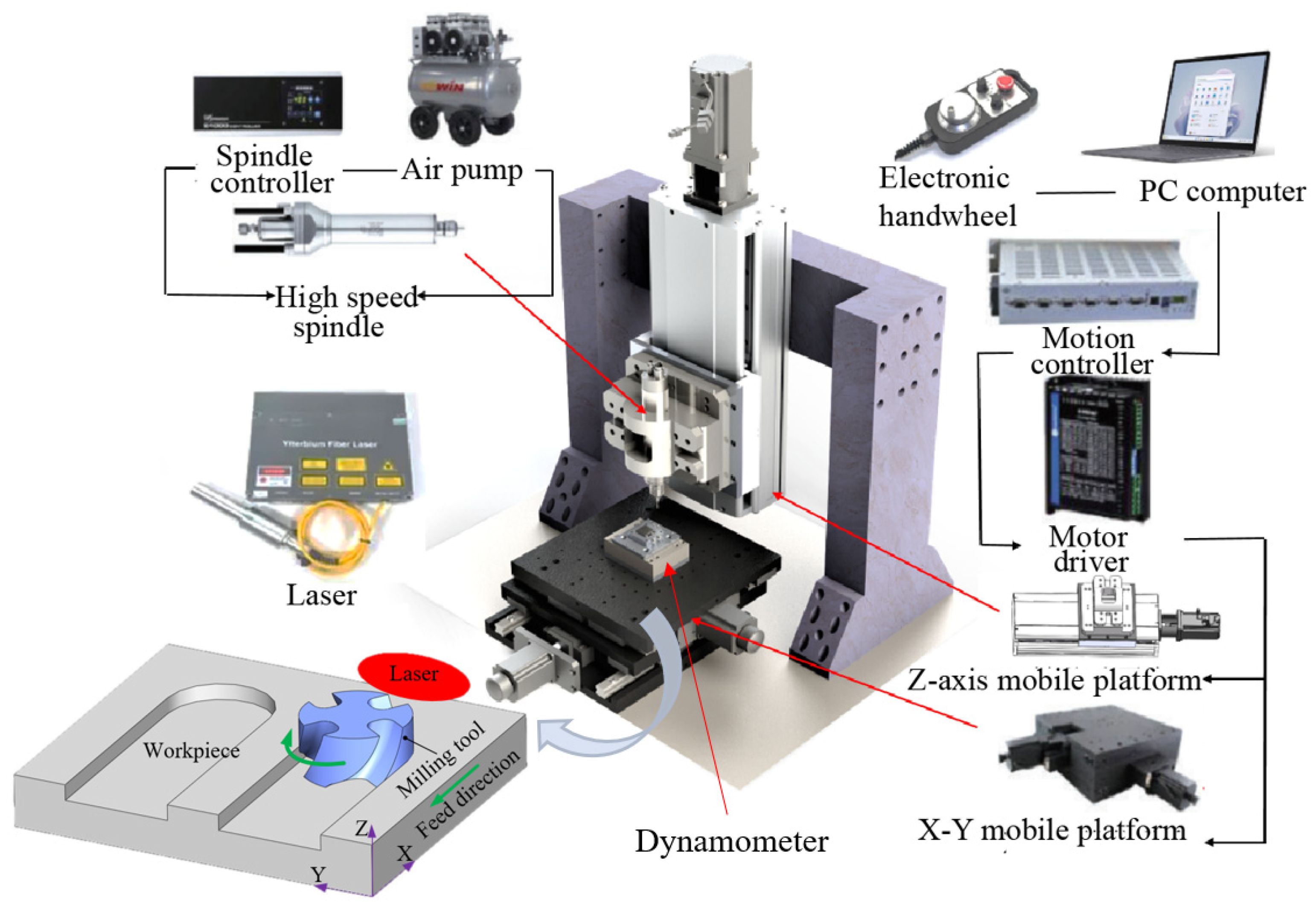
Therefore, in this work, we develop a fully thermal–mechanical coupled 3D FE model of laser-assisted milling of Inconel 718, considering the movement of a laser spot with a milling tool. By combining FE simulations and experiments of laser-assisted milling of Inconel 718, the effect of different processing parameters on the machined surface quality of Inconel 718 is systematically investigated. In Section 2, the methodologies of the experimental setup and FE modelling are elaborated upon. In Section 3, the characteristics of laser-assisted micro-milling including cutting force, machined surface morphology and chip morphology are analyzed. In Section 4, the optimization of processing parameters is carried out.

2. Methodologies

2.1. Experimental Setup of Laser-Assisted Milling of Inconel 718

According to the principle of laser preheating, the experimental layout of the laser-assisted milling platform is designed, with consideration of the precise motion trajectory control between the workpiece, milling tool and laser spot. The experimental device consists of a three-axis linkage motion platform, a laser beam and other auxiliary structures. Figure 1 shows the overall components of the laser-assisted milling platform, in which the three-axis linkage motion platform mainly assists in the precise displacement motion control of the tool and workpiece, the continuous laser is responsible for heating the processing area, and the air pump is mainly responsible for pressurizing the spindle. The dynamometer is used to record the cutting force during the milling process.
The Inconel 718 workpiece has a size of 10 mm × 10 mm × 25 mm. The surface of the Inconel 718 workpiece is rough-milled before the experiment. A coated carbide four-flute end mill is utilized in the laser-assisted milling experiments. The geometrical parameters of the tool are listed in Table 1. The laser is incident along the Y direction, with an incident angle of 30°. The distance from the center of the laser to the edge of the milling tool is 1 mm.

2.2. FE Model of Laser-Assisted Milling of Inconel 718

The FE model of laser-assisted milling of Inconel 718 is established in Abaqus based on the principle of laser preheating, which follows the following assumptions: (1) the tool and workpiece vibration caused by the rigidity of the machine tool during the milling process is not considered; (2) the Inconel 718 material is isotropic; and (3) tool wear during the milling process is ignored.
The Johnson–Cook (J-C) constitutive law is adopted to capture the elastoplastic deformation behavior of Inconel 718 during laser-assisted milling. Table 2 list the material parameters of Inconel 718 and the cemented carbide milling tool. Table 3 list the J-C constitutive parameters of Inconel 718. The milling tool discretized by the first-order tetrahedral elements is set as a rigid body. The milling depth is set to 100 μm in laser-assisted milling of Inconel 718. The Inconel 718 workpiece is discretized by the first-order hexahedral elements (C3D8RT) with a minimum mesh size of 5 μm, as shown in Figure 2. The friction behavior between the milling tool and the workpiece is described by the Coulomb friction law with a friction coefficient of 0.2. The laser heat source with a Gaussian distribution is introduced through a user subroutine to achieve laser loading along a specified path.

3. Characteristics of Laser-Assisted Micro-Milling of Inconel 718

3.1. Cutting Force

Cutting force is an important factor indicating underlying the laser-assisted micro-milling process. The magnitude of the cutting force directly affects the tool wear degree and tool service life. Firstly, a set of typical processing parameters is selected for laser-assisted milling experiments to explore the effect of laser-assisted milling on the cutting force of Inconel 718. The processing parameters (spindle speed n, feed per tooth fz, depth of cut ap and laser power P) are listed in Table 4.
Figure 3 plots the curves of cutting force versus time during the two machining processes. It can be seen from Figure 3 that the cutting force under the two machining processes has the same variation trend: the cutting force in each direction increases rapidly starting when the workpiece contacts the tool and then vibrates around a constant value. In addition, the cutting forces in the X and Y directions are significantly higher than the cutting forces in the Z direction. Furthermore, the cutting forces in the X and Y directions have obvious periodicity. Figure 3 demonstrates that laser assistance has a significant effect on cutting force characteristics. Firstly, the stable values of cutting force in the X, Y and Z directions in laser-assisted milling are 29.6 N, 37.2 N and 15.6 N, respectively, which are 39.7%, 40.5% and 38.8% lower than those in conventional milling. Secondly, while the difference in cutting force in the X and Y directions in laser-assisted milling is small, there is a large difference in the cutting force between the X and Y directions in conventional milling. Finally, laser-assisted milling can significantly reduce the fluctuation of cutting force in the stable stage of milling process, as compared with conventional milling.
The cutting force variation in laser-assisted milling of Inconel 718 obtained via FE simulation is shown in Figure 4. The FE simulation results show that the cutting forces in all directions have obvious periodic fluctuations, which are caused by the periodic cutting in and out of the workpiece using the four-edged milling tool. Comparing the simulation results with the experimental results, it is found that the magnitude and fluctuation characteristics of the cutting force in each direction are similar to the experimental results, thus verifying the accuracy of the FE model.

3.2. Machined Surface Morphology

Surface roughness is an important factor to represent machined surface quality. In order to study the effect of laser-assisted milling on the machined surface quality of an Inconel 718 workpiece, a white light interferometer and a scanning electron microscope (SEM) are utilized to characterize the surface quality via conventional milling and laser-assisted milling. The Inconel 718 workpiece was ultrasonically cleaned before testing, and the test results are shown in Figure 5. Figure 5a,b show the machined surface morphology of Inconel 718 in conventional milling and laser-assisted milling, respectively. The surface morphology of Inconel 718 processed via conventional milling is poor, with a surface roughness Sa of 264 nm. There are obvious milling tracks and pits observed on the machined surface of Inconel 718, as shown in Figure 5a. In contrast, the surface morphology of Inconel 718 processed via laser-assisted milling is better, with a reduced surface roughness Sa of 157 nm. Compared with conventional milling, the machined surface roughness of Inconel 718 via laser-assisted milling is reduced by 40.5%. Therefore, laser-assisted milling has a significant effect on improving the machined surface quality of Inconel 718.
Figure 6a,b show FE simulation results of the machined surface topography of Inconel 718 via conventional milling and laser-assisted milling, respectively. As shown in Figure 6a, the machined surface quality of Inconel 718 is poor, with large undulations after conventional milling. As shown in Figure 6b, the machined surface of Inconel 718 is relatively flat, with small fluctuations after the laser-assisted milling. The surface roughness of Inconel 718 after milling is calculated via the least square method using the average arithmetic deviation. The machined surface roughness Sa of Inconel 718 after conventional milling and laser-assisted milling is 289 nm and 122 nm, respectively. Thus, compared with conventional milling, the machined surface roughness of Inconel 718 from laser-assisted milling is reduced by 57.8%, which is similar to the experimental results.

3.3. Chip Morphology

Figure 7a,b show the experimental results of chip morphology of Inconel 718 in conventional milling and laser-assisted milling, respectively. During conventional milling, the chip is broken. Specifically, most of the chips are torn with large fractures, and the jagged shape is not obvious. It can be seen from Figure 7b that during the laser-assisted milling process, the shape of the chips is relatively neat with obvious jagged shapes, and the overall chips are in a spiral shape.
Figure 8a,b show the FE simulation results of chip morphology of Inconel 718 in conventional milling and laser-assisted milling, respectively. The simulation and experimental results of chip morphology are similar to each other. Inconel 718 has relatively high hardness and strength. During conventional milling, the cutting tool squeezes the chips more significantly, and the chips are easily broken, resulting in short and broken chips being generated. During laser-assisted milling, the laser is irradiated on the workpiece surface, which increases the temperature of the cutting area and subsequently reduces the hardness, elastic modulus and shear modulus of the material, making it easier to produce neatly shaped jagged chips.
Figure 9a,b show the experimental results of tool wear in conventional milling and laser-assisted milling of Inconel 718 with a cutting length of 50 mm, respectively. Due to the high hardness of the workpiece and the intermittent cutting characteristics of milling, large vibrations are generated during conventional milling, resulting in serious wear of the rake face and flank face of cutting tool, as shown in Figure 9a. During the laser-assisted milling of Inconel 718, laser heating can soften the workpiece and can reduce the material strength, thereby reducing tool wear.
It should be noted that tool wear cannot be observed in the FE simulation, since the milling tool is set as a rigid body. However, the residual stress distribution on the workpiece surface after different milling methods can be extracted through FE simulation, from which the tool wear can be estimated. Figure 10 shows the residual stress distribution on the workpiece surface under different milling methods. Figure 10a demonstrates that stress concentration occurs at multiple positions on the workpiece surface after conventional milling, especially at the edge position. Figure 10b demonstrates that the residual stress distribution on the workpiece surface after laser-assisted milling is relatively uniform and that there is no stress concentration observed. The calculated average residual stress on the workpiece surface after conventional milling and laser-assisted milling is 582 MPa and 501 MPa, respectively. Compared with conventional milling, the average residual stress of the workpiece surface from laser-assisted milling is reduced by 13.9%. Therefore, laser-assisted milling can reduce the residual stress on the workpiece surface and can optimize the distribution of surface residual stress. When the residual compressive stress is too large, the brittleness of the tool coating will increase, which in turn will aggravate the wear of the coated carbide tool. Laser-assisted milling can reduce the residual compressive stress of Inconel 718 in the milling process, thereby reducing tool wear and prolonging tool life.

4. Parameter Optimization of Laser-Assisted Micro-Milling of Inconel 718

4.1. Selection Principle of Processing Parameters

Firstly, it is necessary to select the appropriate processing parameters of conventional milling according to the milling characteristics of Inconel 718. In this work, combining the characteristics of micro-milling and the performance of the laser-assisted milling platform, the cutting parameters of Inconel 718 including spindle speed of 1000~3000 r/min, feed per tooth of 1.2~3.6 μm/z and milling depth of 0.08–1.6 mm are selected.
The principle of laser-assisted milling is to locally heat the material removal area and to then mill the material at a specific temperature. Therefore, temperature is the main factor affecting the processing characteristics of materials during laser-assisted milling. Based on the material properties of Inconel 718, the range of processing parameters can be reasonably selected by controlling the temperature in the cutting area.
The processing parameters of laser-assisted milling include milling parameters and laser parameters. The material removal process of Inconel 718 is relatively complicated, and there are many factors affecting its milling processability. In addition, Inconel 718 is difficult to process due to its high strength and high hardness. Tool life is short, and experimentation costs are high in the milling process of Inconel 718. When Inconel 718 is heated to 650–950 °C, the tensile strength, elastic modulus and shear modulus of the material decrease with the increase in temperature. Therefore, laser parameters should be selected around this temperature range.
In this work, the absorption rate of the Inconel 718 workpiece is measured firstly through experiments and simulations, and then, the FE simulation model of laser-assisted milling is established. The processing parameters are preliminarily selected according to the material properties of Inconel 718. Secondly, the temperature of the processing area under different laser powers is calculated by performing FE simulation, and the range interval of the laser parameters is preliminarily obtained. Finally, the milling parameters are also reasonably selected to conduct milling experiments based on the laser parameters obtained from FE simulation. The influence of different processing parameters on the experimental results is further analyzed, including cutting force, surface roughness, tool wear, chip shape and burr size. And, the processing parameters are iteratively adjusted to achieve an ideal processing quality.

4.2. Selection of Process Parameters

It is necessary to simultaneously meet both the cutting conditions and temperature conditions for improving the machinability of Inconel 718 and prolonging the service life of the tool in the laser-assisted milling of Inconel 718. The temperature of the cutting area needs to meet the following conditions: (1) The temperature needs to be controlled within 650–950 °C. It is necessary to reduce the tensile strength, elastic modulus and shear modulus of the material by softening the material and to ensure that the central temperature cannot be higher than the melting point of the workpiece, resulting in the melting of the material itself and the combustion of the chip. (2) The milling tool needs to maintain an appropriate distance from the laser spot. If the distance is too close, the laser may irradiate the tool, destroy the tool coating, and aggravate the tool wear. If the distance is too far, the temperature of the contact position between tool and workpiece will not reach 650 °C, and the laser cannot soften the workpiece and improve the processing quality.
Laser power is the main parameter affecting temperature. Combined with the experiment and simulation of measuring laser absorption rate, the laser power parameter range is selected as 10~30 W. The laser spot diameter also affects the laser energy density. If the spot diameter is too large, the temperature rise within the workpiece will be too slow and the temperature of the cutting area will not meet the requirements. If the spot diameter is too small, the temperature of the laser center will be too high, resulting in ablation of the material. In this work, the laser spot diameter d is selected to be 0.6–1.4 mm according to the actual size of the tool and the workpiece. According to the milling characteristics of Inconel 718, the cutting parameters selected in this work are spindle speed n 1000–3000 r/min, feed per tooth fz 1.2–3.6 μm/z and milling depth ap 0.08–1.6 mm.

4.3. Experimental Parameter Design and Result Statistics

The size of the Inconel 718 workpiece used in the experiment is 10 mm × 10 mm × 25 mm. The tool is a cemented carbide four-edge end mill with a diameter of 1 mm, a spiral angle of 35° and a rake angle of 5°. The laser is incident with an incident angle of 30° in the Y-axis direction. The distance δ between the laser center and the milling tool boundary is set to 1 mm, which can not only ensure the temperature during processing but also prevent the laser from burning the tool. According to the principle of process parameter selection, the laser-assisted milling parameters are determined as listed in Table 5.
The “orthogonal experiment” is a method in experimental design that systematically varies multiple factors simultaneously, ensuring that the effects of each factor are independent. It allows for efficient exploration of different factors’ impact on the outcome, identifying individual effects and their interactions. According to the laser-assisted milling parameters, a five-factor and five-level orthogonal experiment is designed. The experimental results are listed in Table 6. From the experimental results of the 8th, 15th, 16th and 23rd groups, it can be seen that when the laser power is higher than 20 W and the laser spot diameter is less than 1 mm, the temperature within the cutting area is too high due to excessive laser power or too small of a laser spot diameter. The surface roughness increases sharply, which affects the influence of other cutting parameters on the surface roughness. Therefore, in order to ensure that the processing parameters of laser-assisted milling are within a reasonable range, the influence of laser power between 25 and 30 W on surface roughness is not considered when analyzing the orthogonal experimental results.
In this work, the results of the orthogonal experiment are analyzed via a range analysis. According to the range analysis method, the influence of processing parameters on cutting force is fz > n > ap > P > d, among which fz has the greatest influence on cutting force and spot diameter has the least influence on cutting force. From the point of view of reducing cutting force, the optimal processing parameters of laser-assisted milling of Inconel 718 are as follows: n = 2500 r/min, fz = 0.08 μm/z, ap = 0.08 mm, P = 20 W and d = 1.4 mm.
According to the range analysis method, the influence of processing parameters on surface roughness is ap > fz > d> n > P, among which ap has the greatest influence on surface roughness, and laser power has the least influence on surface roughness. From the point of view of reducing surface roughness, the optimal processing parameters of laser-assisted milling of Inconel 718 are as follows: n = 2500 r/min, fz = 0.08 μm/z, ap = 0.1 mm, P = 20 W and d = 1 mm.
According to the optimal processing parameters obtained from the orthogonal experiments, conventional milling and laser-assisted milling experiments are carried out. 
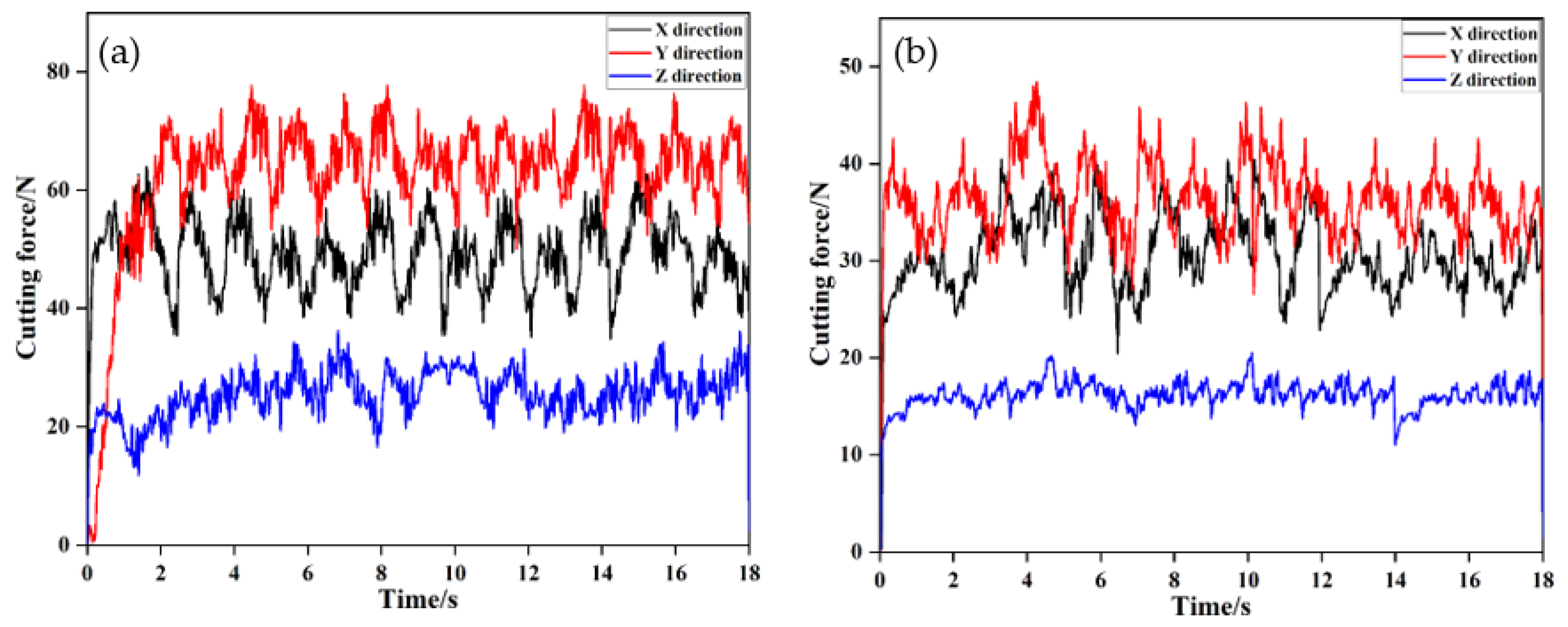
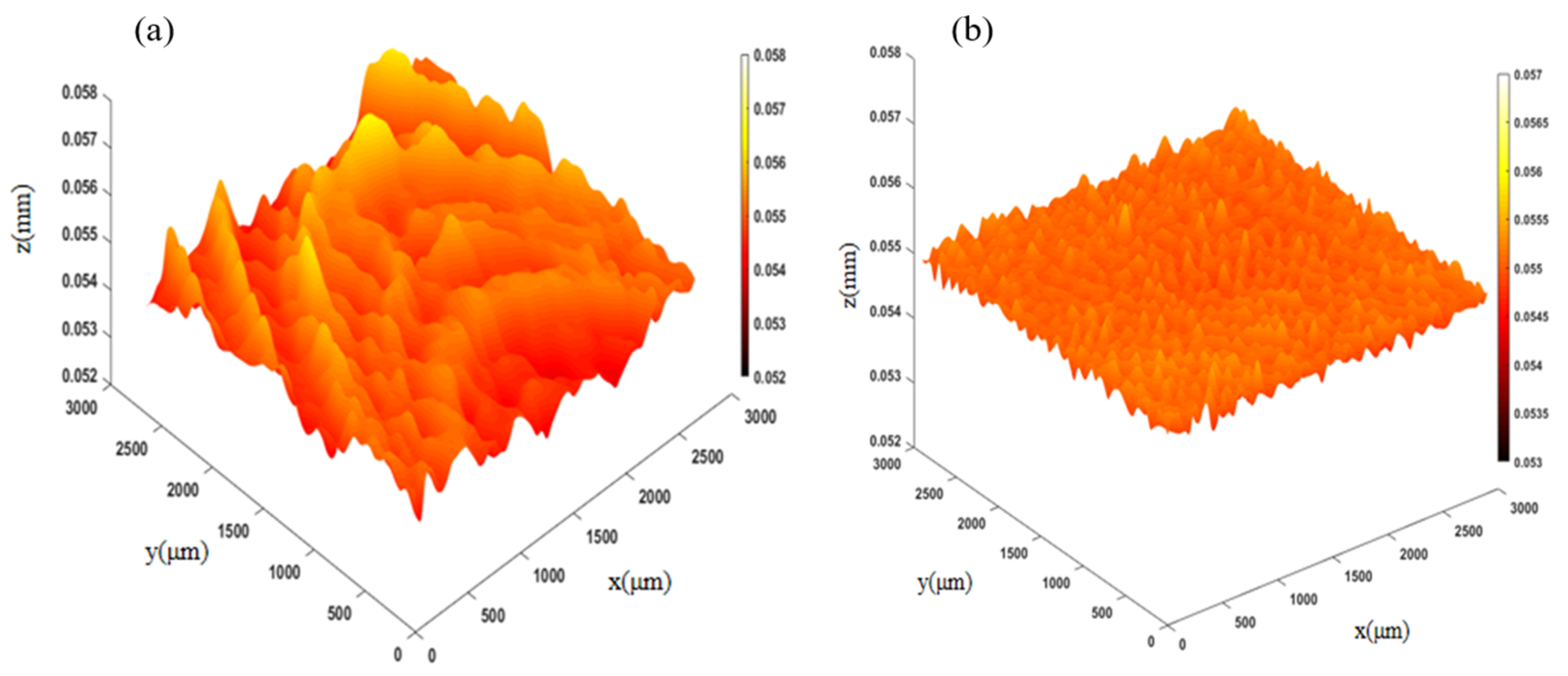
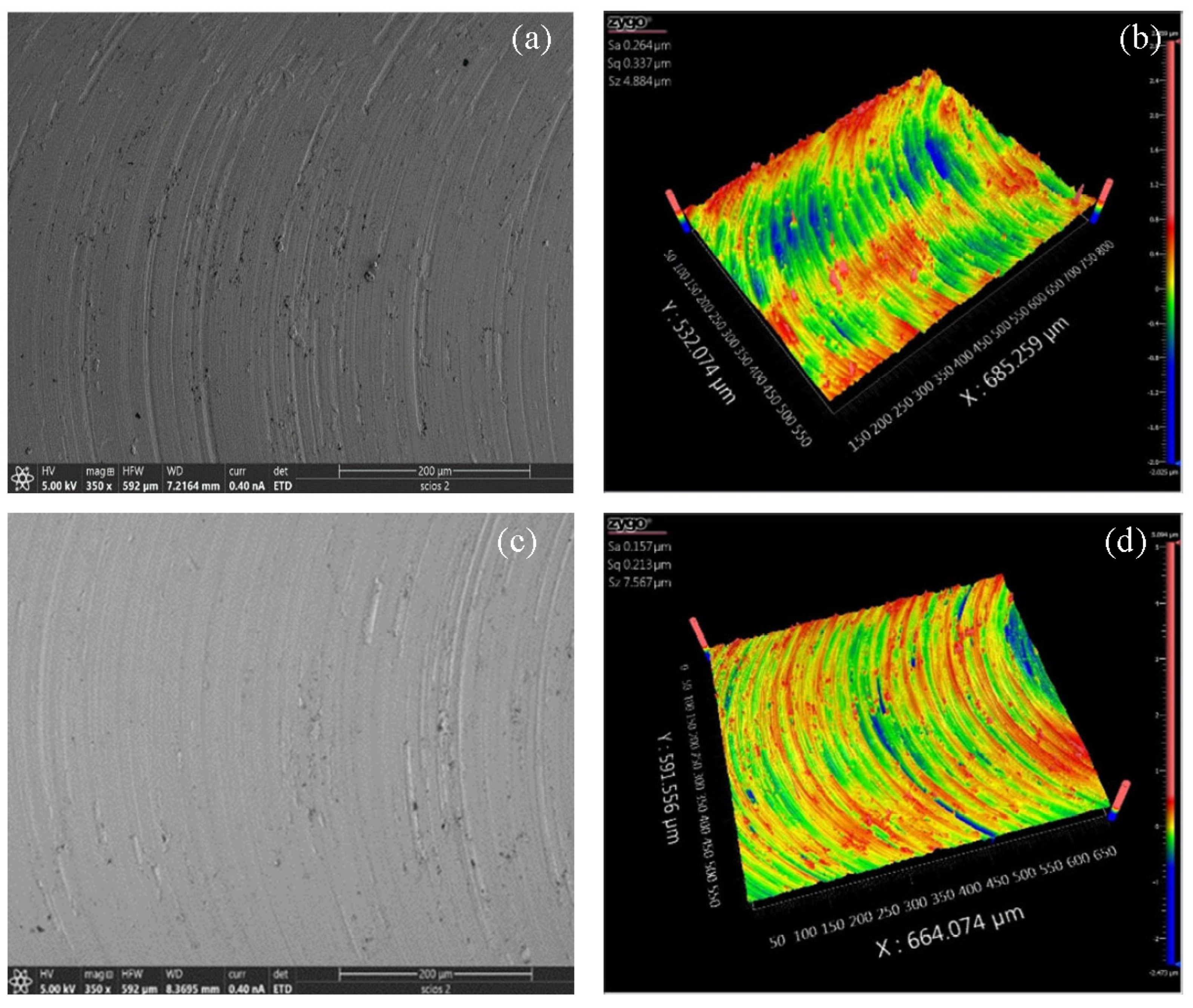
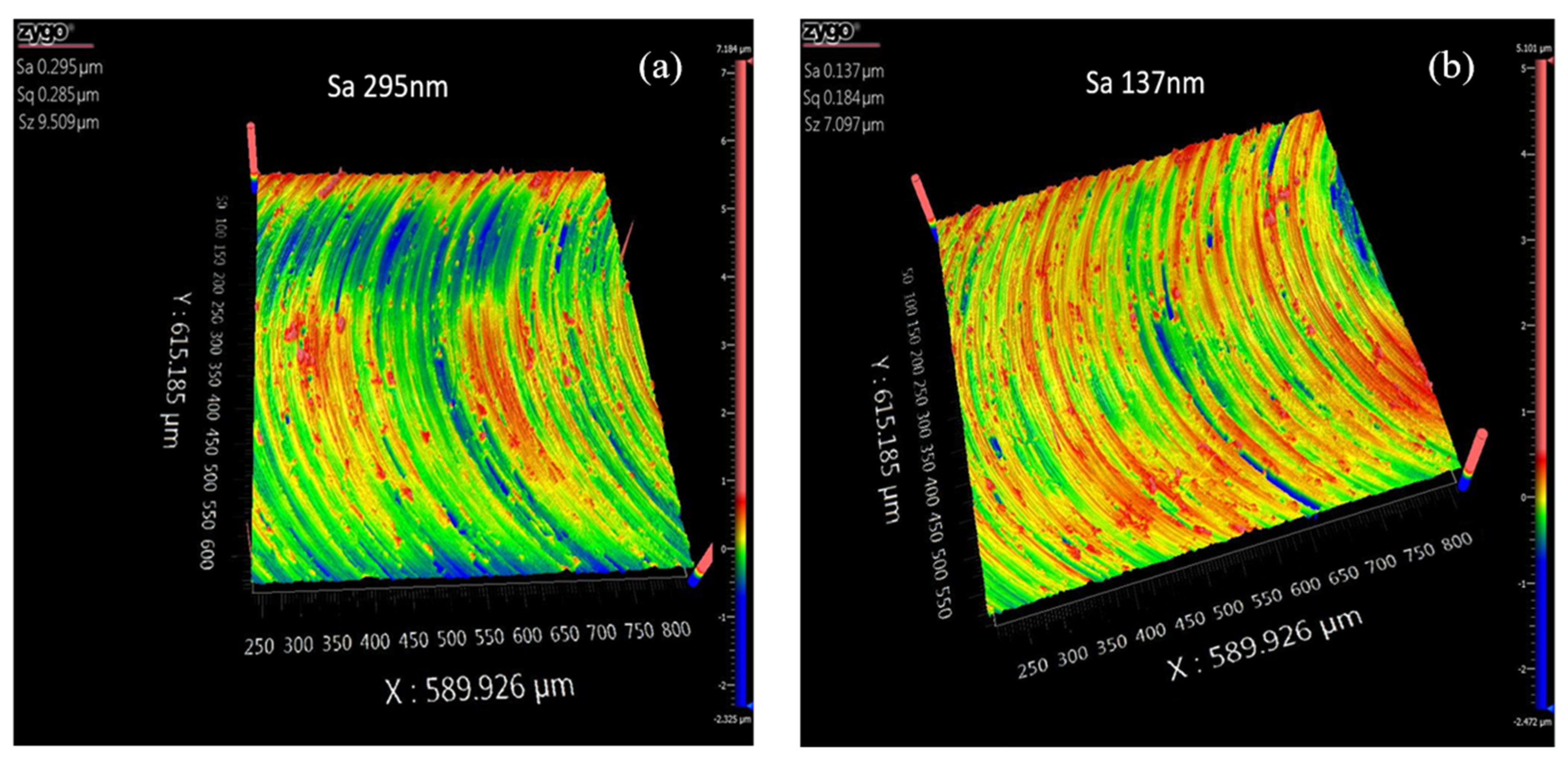
Figure 11 shows the surface morphologies of the workpiece under conventional milling and optimal laser-assisted milling. It can be seen from Figure 11a that the surface integrity of Inconel 718 under the conventional milling workpiece is poor, with a surface roughness Sa of 295 nm. It can be seen from Figure 11b that the machined surface of Inconel 718 under the optimal process parameters of laser-assisted milling is relatively flat. The surface integrity is significantly improved with a decreased surface roughness Sa of 137 nm.

4.4. Effect of Laser Power on Cutting Force

Laser-assisted milling improves the cutting performance of the material by preheating the processing area, thereby reducing cutting resistance and improving the surface quality of the machined surface. The laser power is an important factor affecting the temperature of the processing area. Therefore, the single-factor experiment of laser power is carried out to explore the influence of laser power on cutting force, chip morphology, tool wear and surface morphology in the laser-assisted milling of Inconel 718. The experimental parameters are listed in Table 7.
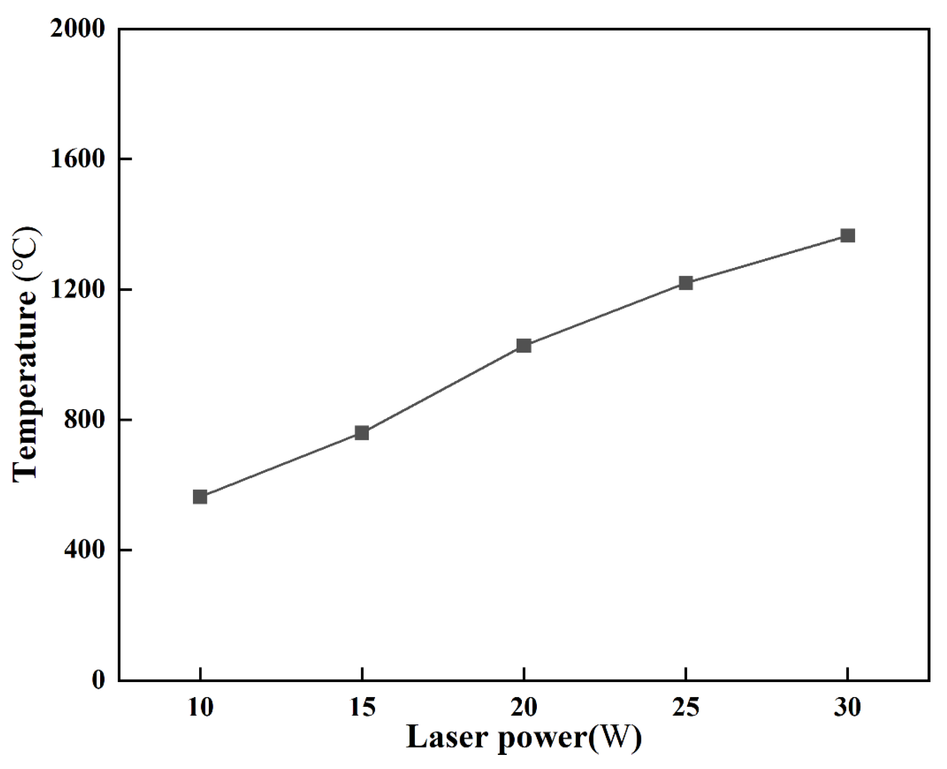
In laser-assisted milling of Inconel 718, the tensile strength, elastic modulus and shear modulus of the material decrease with the increase in temperature in a certain temperature range. Therefore, it is necessary to find out the correlation of laser power with the temperature of processing area. The laser preheating experiments are carried out to explore the relationship between the surface temperature of the Inconel 718 workpiece and the laser power. The surface temperature-laser power curves obtained from the experiments are shown in Figure 12. It can be seen from Figure 12 that the surface temperature (°C) of the Inconel 718 workpiece increases with the increase in laser power.
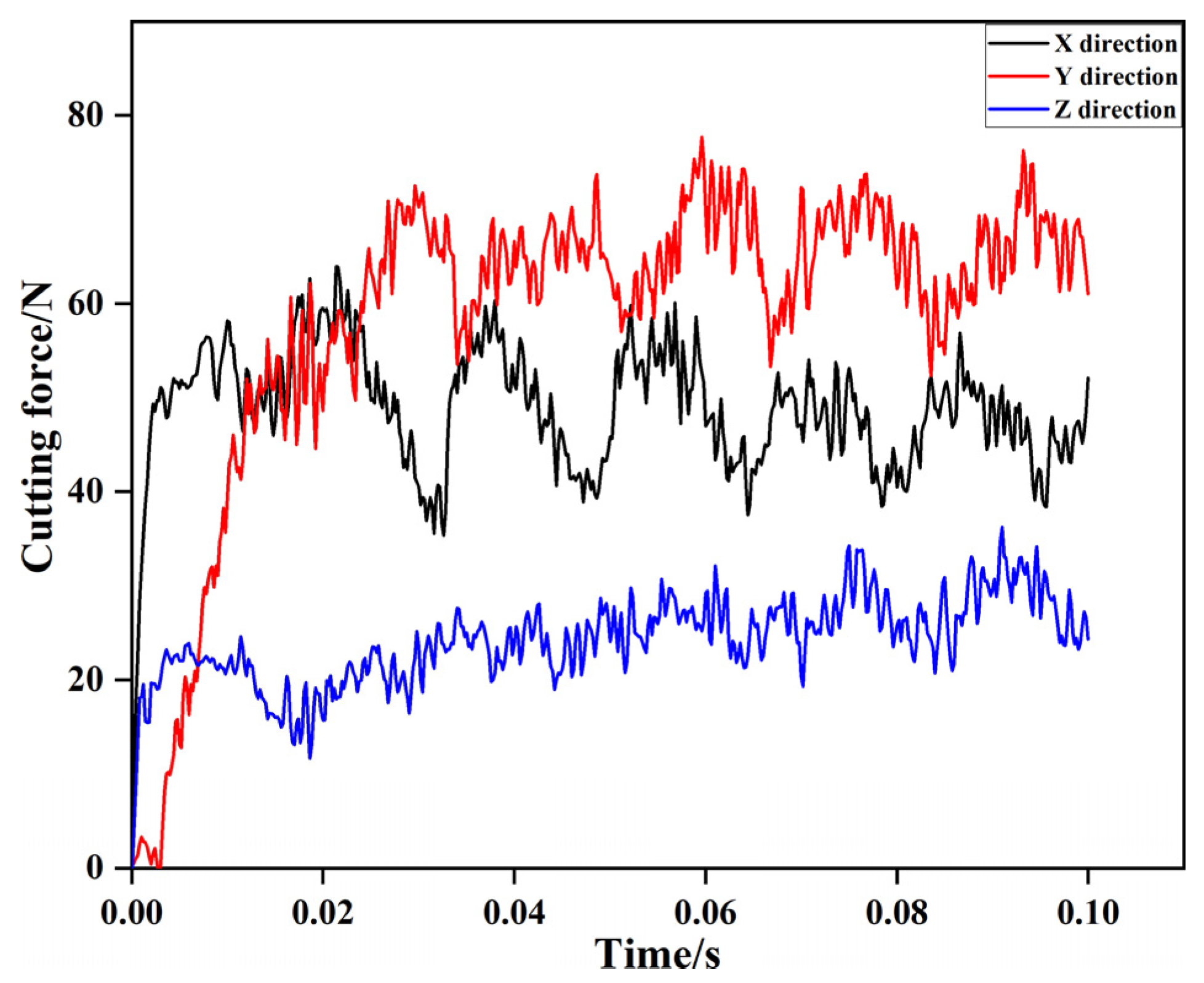
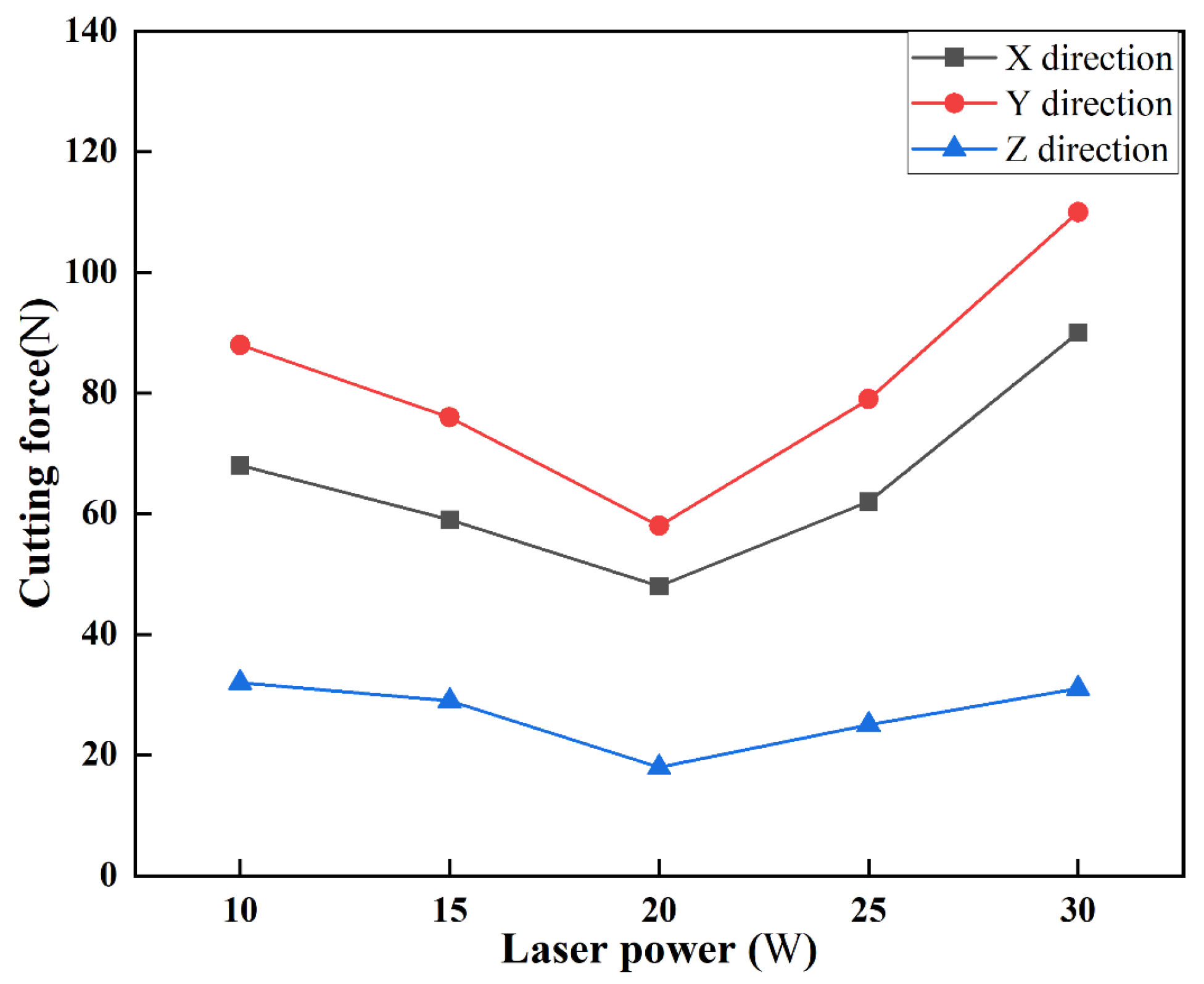
The variation in cutting force with laser power in laser-assisted milling of Inconel 718 is plotted in Figure 13. As shown in Figure 13, the laser power has a significant effect on the cutting force characteristics of the milling process. Firstly, before the laser power reaches 20 W, with the increase in the temperature of processing area, the tensile strength, elastic model and shear modulus of the material decrease, and the cutting force in all directions decreases to varied degrees. However, when the laser power is higher than 20 W, the tensile strength, elastic model and shear modulus of the material increase, and the cutting forces in the X, Y and Z directions also increase. Secondly, the laser power has a great influence on the cutting force in the X and Y directions and has trivial influence on the cutting force in the Z direction. Finally, when the laser power is 20 W, the cutting force in the X, Y and Z directions is the smallest. Therefore, when the laser power is 20 W, the cutting force reduction effect is mostly significant.

4.5. Effect of Laser Power on Surface Roughness

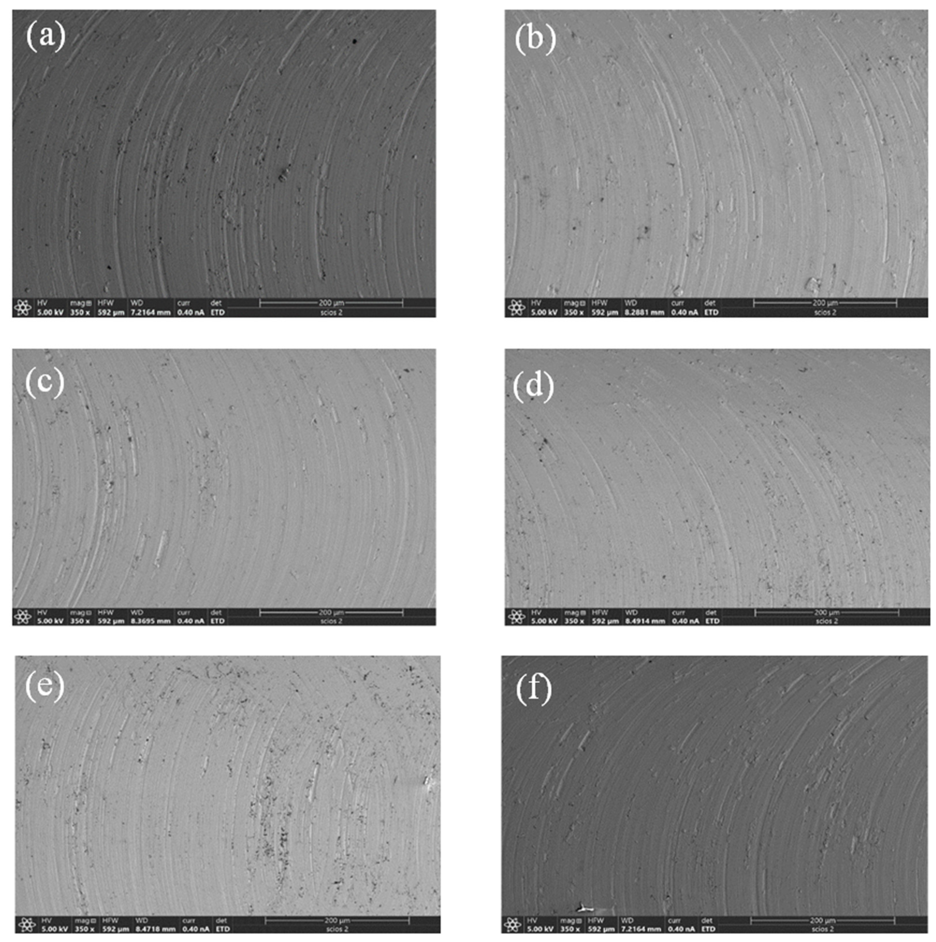
Figure 14 shows the machined surface morphology of Inconel 718 under different laser powers, which indicates that the machined surface morphologies under different laser powers are significantly different. It can be seen from Figure 14 that there are obvious cutting marks formed on the machined surface via conventional milling. With the increase in laser power, the cutting marks on the machined surface gradually decrease. When the laser power is 20 W, it can be seen that the cutting marks on the machined surface almost disappears, and the machined surface is smooth. However, when the laser power is higher than 20 W, the workpiece surface is ablated due to the high temperature in the processing area, the tool wear is serious and the surface quality of the machined surface gradually deteriorates.
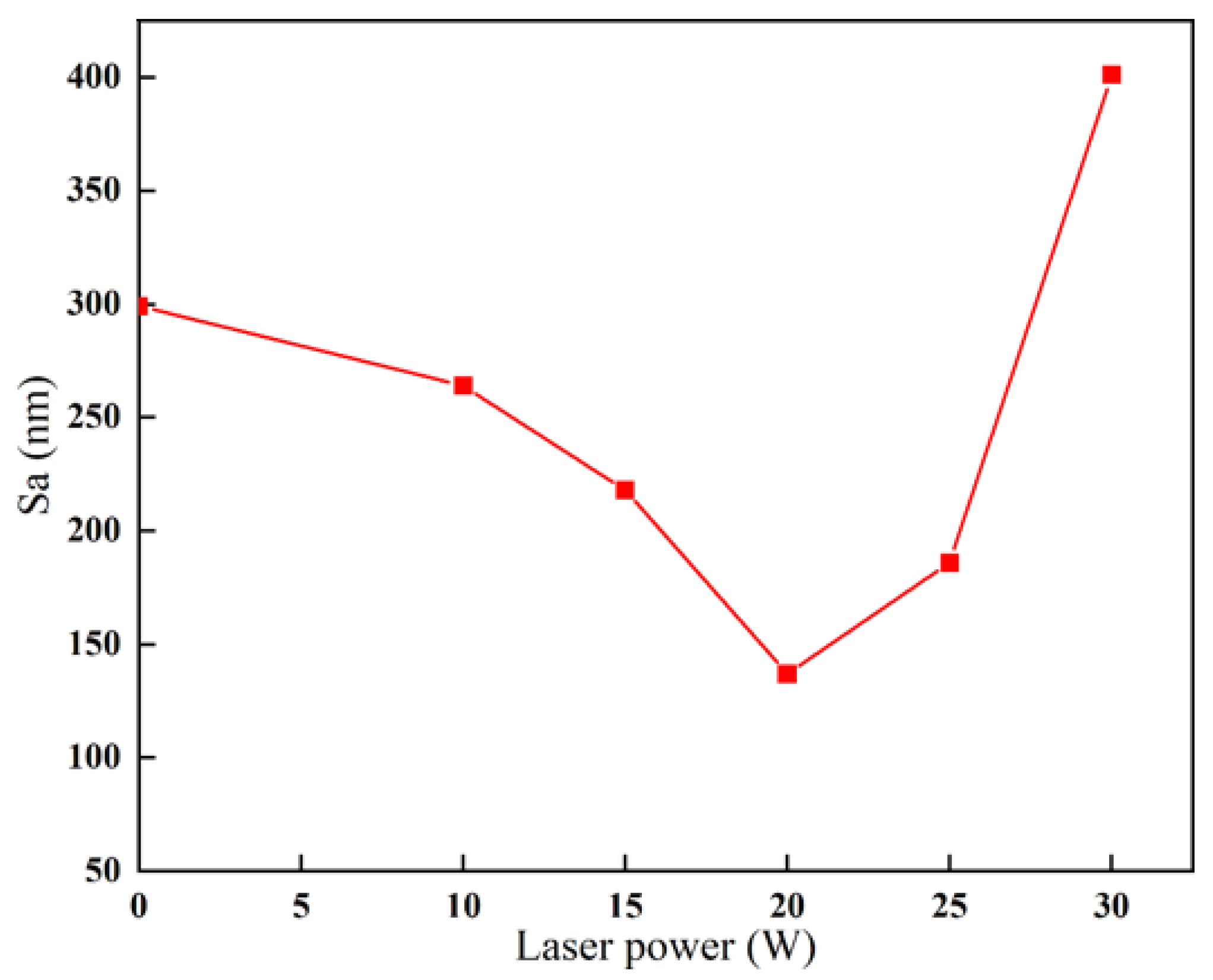
Figure 15 plots the variation in surface roughness Sa (nm) of Inconel 718 with laser power. It can be seen from Figure 15 that the Inconel 718 workpiece surface is rough with a surface roughness of 299 nm under conventional milling, corresponding to a laser power of 0 W. With a laser power below 20 W, the surface roughness gradually decreases. When the laser power is 20 W, the surface roughness is reduced to 142 nm, which is 52.5% lower than that of conventional milling. However, when the laser power is higher than 20 W, the temperature of the processing area is too high, resulting in melting of the tool coating, accompanied by serious tool wear and increased surface roughness. Therefore, under an appropriate laser power, laser-assisted milling can significantly reduce the surface roughness of the workpiece.

4.6. Effect of Laser Power on Chip Morphology

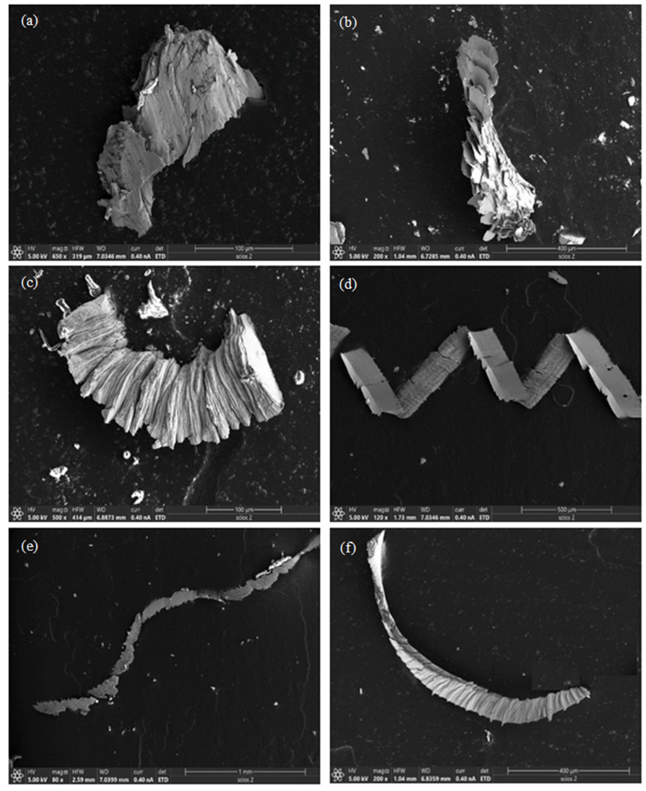
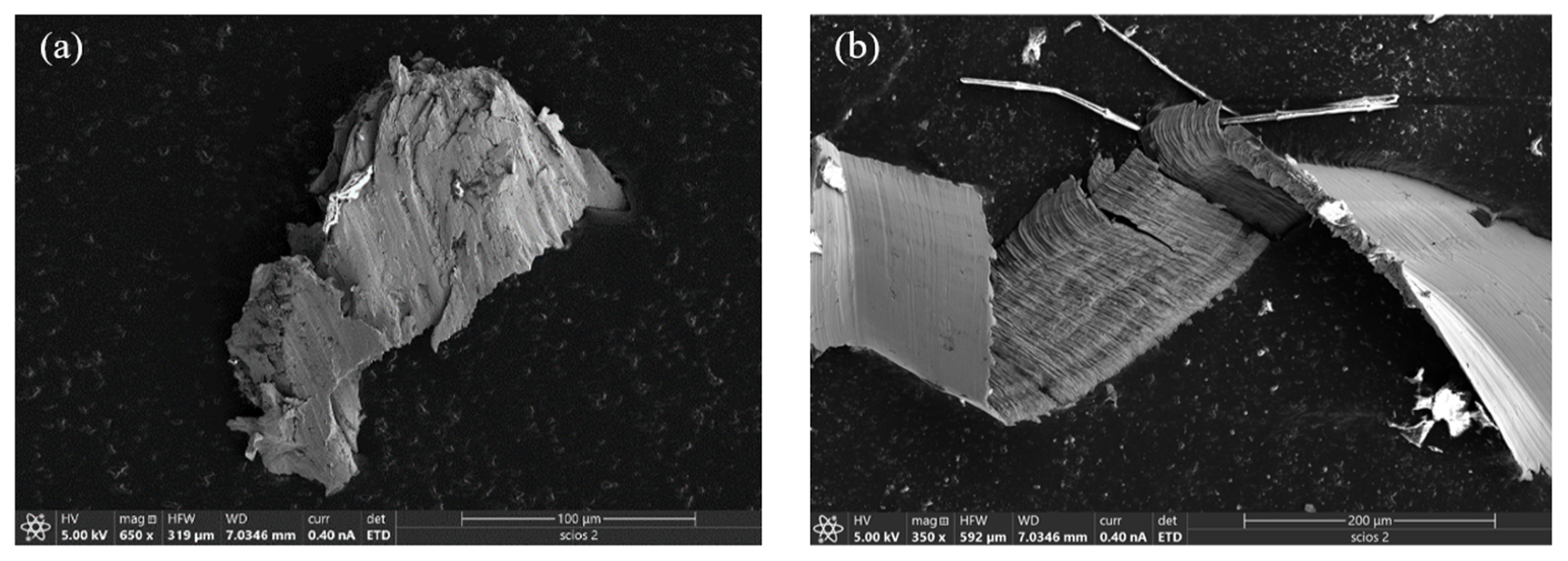
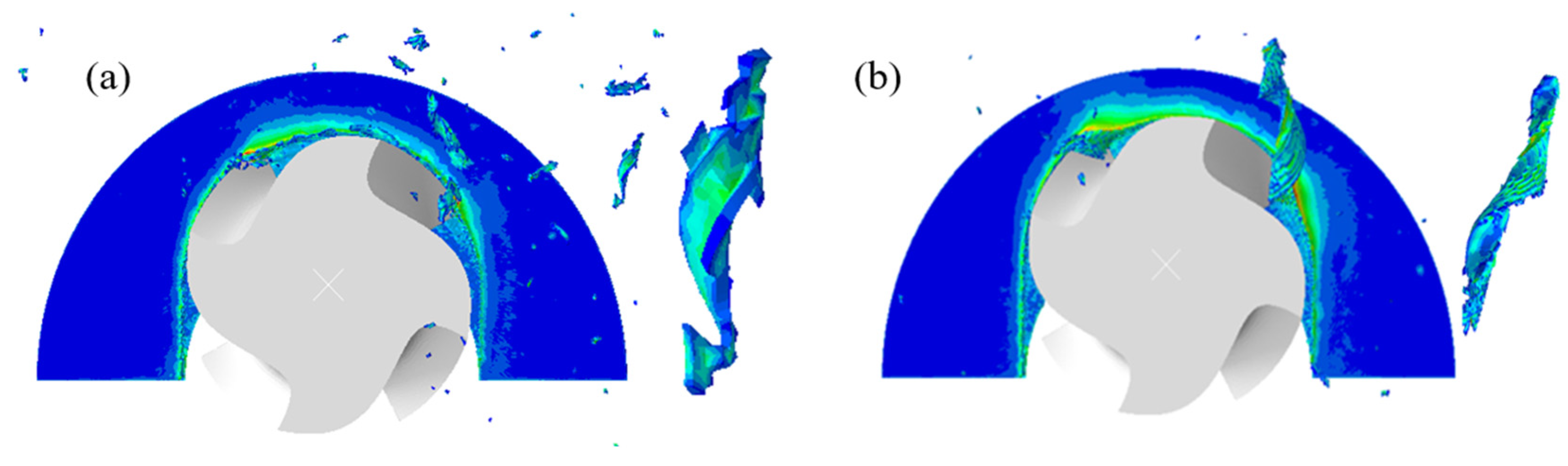
Figure 16 shows the chip morphologies via conventional milling and laser-assisted milling. It can be seen from Figure 16 that the chip shape generated in conventional milling is discontinuous. Most of the chips are torn and broken, and the serrated shape is not obvious. In laser-assisted milling, however, the chip morphology is relatively neat, the tear fracture decreases, and obvious serrated chips appear. With the increase in laser power, the chip morphology gradually changes from broken to spiral, and the spiral is the most obvious when P = 20 W. However, when P = 25 W, the spiral shape of the chip decreases and becomes a banded chip. When the laser power exceeds 25 W, the length (mm) of the chip becomes shorter and the degree of curling increases.
Due to the high hardness and strength of Inconel 718, the extrusion of the chip by the tool during conventional milling is serious and the chip is easy to break, resulting in a shorter and broken chip shape. In laser-assisted milling, however, laser irradiation on the workpiece surface increases the temperature of the processing area, and the hardness, elastic modulus and shear modulus of the material decrease. Consequently, it tends to produce neat serrated chips during laser-assisted milling. When the laser power is too large, the chip softens significantly, resulting in the chip being more likely to break and the chip length becoming shorter.

4.7. Effect of Laser Power on Tool Wear

In the conventional milling of Inconel 718, due to the high hardness of the workpiece material and the intermittent cutting of the milling process, a large vibration is generated during the cutting process, resulting in serious tool wear. 
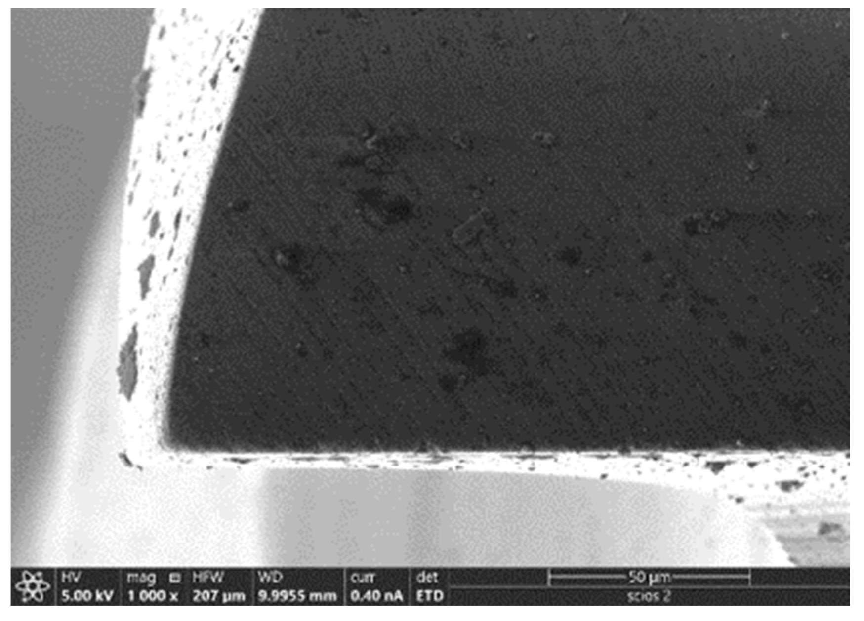
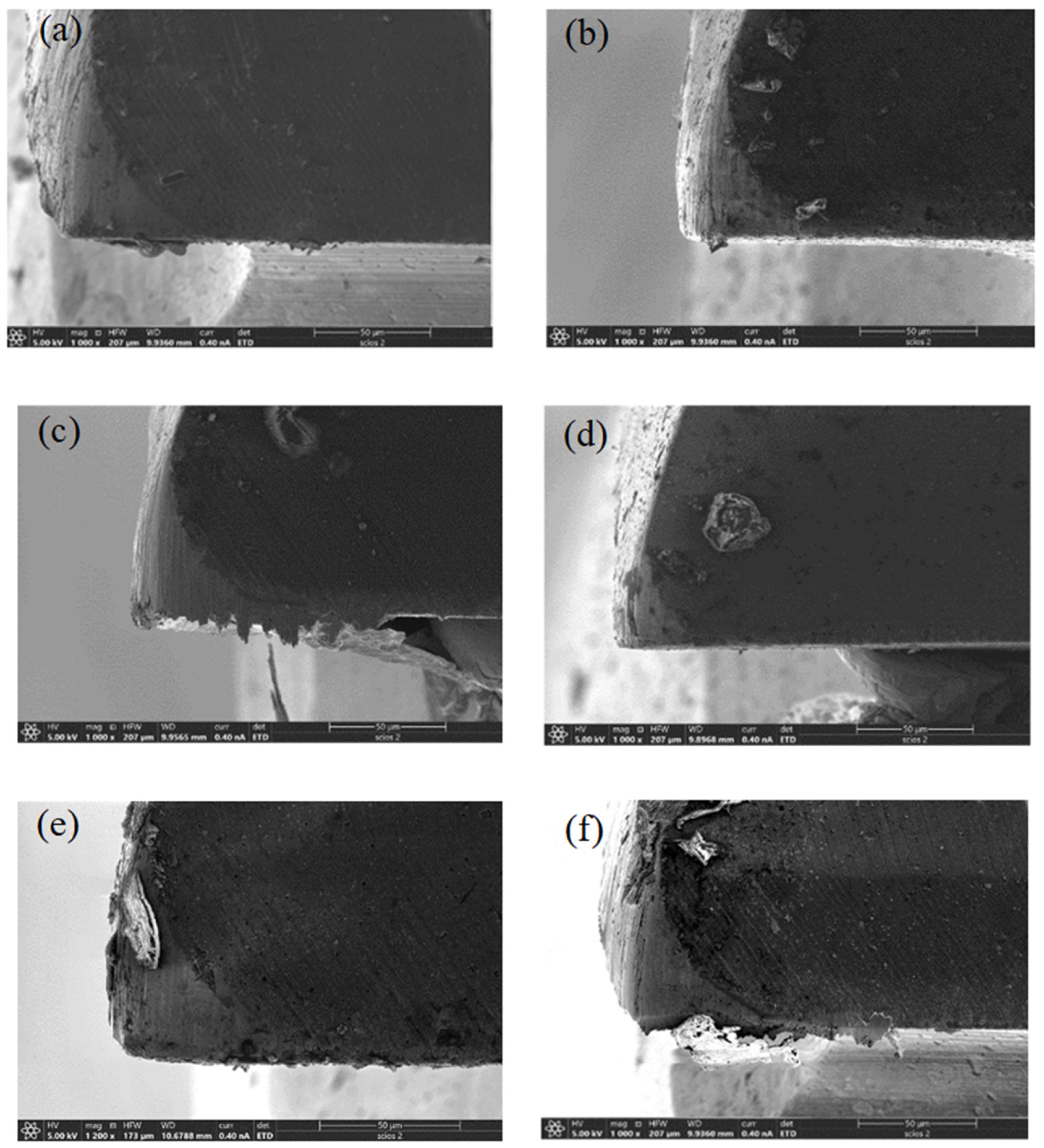
Figure 17 shows the surface morphology of the new milling tool. 
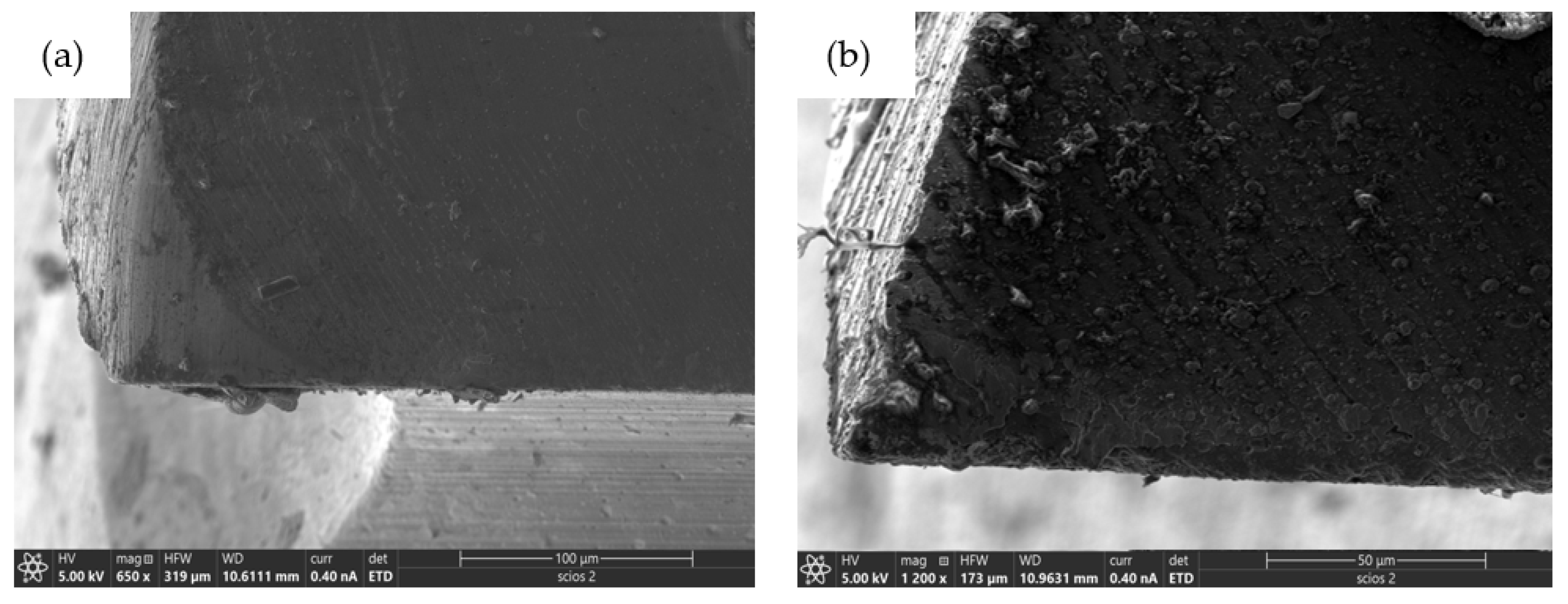
Figure 18 shows the wear of the tool rake face and the flank face at a milling distance of 50 mm. It can be seen from Figure 18 that the rake face and the flank face of the tool are seriously worn in conventional milling. With the increase in laser power, the degree of tool wear gradually decreases. When P = 20 W, the degree of tool wear is the smallest. When the laser power is higher than 20 W, the high temperature of the processing area destroys the tool coating, and the tool is in direct contact with the workpiece, which aggravates the tool wear. Due to the softening of the material, the chips are more likely to stick to the tool surface, forming a built-up edge.

4.8. Effect of Laser Power on Burr Formation

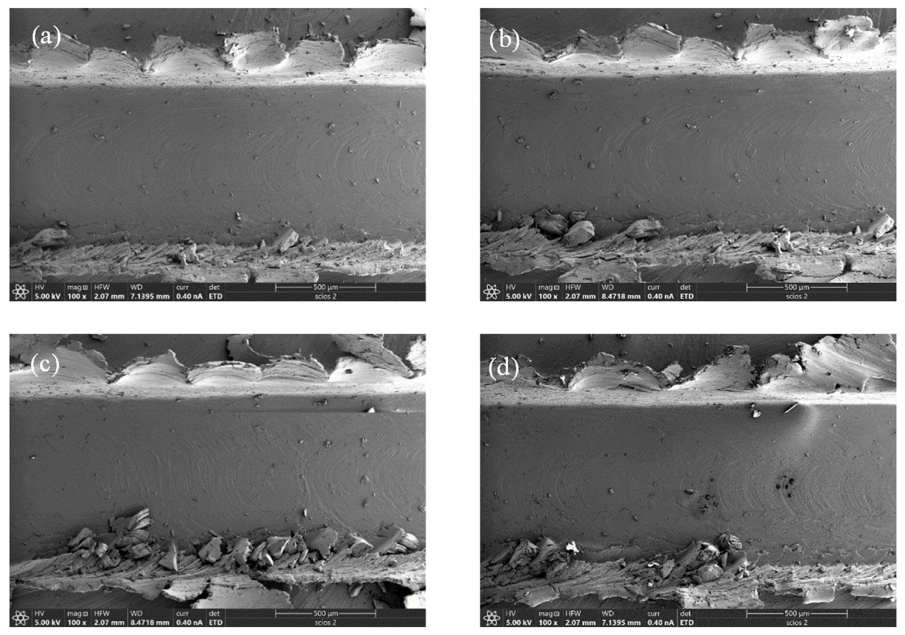
Figure 19 shows the formation of burrs on both sides of the groove under different laser powers. As shown in Figure 19, in conventional milling, the burr on the reverse milling side of the groove is a large spiral burr, and the burr on the down milling side is a large sheet burr. Both sides of the burr surface have a wide texture, which is formed via the accumulation of materials during intermittent milling processing. In laser-assisted milling, with the increase in laser power, the size of the flaky burr on the down milling side becomes larger, the spiral burr on the reverse milling side becomes broken and the processing quality of the groove boundary becomes worse. The reason for this phenomenon is that the laser heating softens the Inconel 718 material, which significantly improves the plastic deformation ability, resulting in a larger burr size.
Although laser-assisted milling of Inconel 718 is not ideal for suppressing groove burr size, a comprehensive comparative study of cutting force, machined surface quality, chip morphology and tool wear demonstrates that laser-assisted milling can effectively improve the cutting performance of Inconel 718 compared with conventional milling, in terms of reduced cutting force, delayed tool wear and decreased surface roughness. Thus, it is systematically demonstrated that the laser-assisted milling has great potential in improving the cutting performance of Inconel 718.

5. Conclusions

In this work, a three-axis linkage laser-assisted milling platform is built, and a 3D thermal–mechanical coupling FE model of laser-assisted milling is established. The influence of laser-assisted milling on the processing characteristics of Inconel 718 is studied by combining experiments and simulations. The following conclusions are obtained:
(1) Laser heating can reduce the elastic model, tensile strength and shear modulus of Inconel 718, which improves the cutting performance of Inconel 718 via laser-assisted milling.
(2) Within a laser power ranging from 10 to 30 W, the laser-assisted milling process can effectively reduce the cutting force by 40.5% and prolong the service life of the tool.
(3) Through parameter optimization, laser-assisted milling can greatly reduce the surface roughness Sa of an Inconel 718 workpiece to 137 nm, which is reduced by 52.5% from conventional milling.

Author Contributions

Conceptualization, H.Z. and J.Z.; data curation, F.C. and W.H.; funding acquisition, H.Z. and J.Z.; project administration, Z.L. and T.S.; software, F.C. and W.H.; investigation, H.Z. and J.Z.; writing—review and editing, H.Z., F.C., W.H. and J.Z. All authors have read and agreed to the published version of the manuscript.

Funding

The authors greatly acknowledge the support by the Science Challenge Project of China (No. TZ2018006-0201-02 and TZ2018006-0205-02).

Institutional Review Board Statement

Not applicable.

Informed Consent Statement

Not applicable.

Data Availability Statement

The data used in current study cannot be opened because it is an on-going work.

Conflicts of Interest

The authors declare no conflict of interest.

References

  1. Yue, C.; Liu, Z.; Nan, Y.; Yan, F.; Gao, H. Research Progress in the Surface Integrity of Metal Milling. J. Harbin Univ. Sci. Technol. 2020, 25, 38–49. [Google Scholar]
  2. Varma, L. Predictive study of Inconel 718 mechanical properties at subzero temperatures. Adv. Mater. Process. Technol. 2020, 6, 122–128. [Google Scholar]
  3. Zhang, H.J.; Sun, C.Y.; Liua, M.; Gao, F. Analysis of the optimization of tool geometric parameters for milling of Inconel 718. In Proceedings of the International Conference on Humanities and Social Science Research, Nanchang, China, 25–27 May 2018; pp. 253–259. [Google Scholar]
  4. Li, Q.; Liu, L.; Song, X.; Li, H.; Liu, H. Turning Simulation of Nickel-Based Superalloy Inconel 718 Based on ABAQUS and Python. Instrum. Technol. 2019, 53, 60–63. [Google Scholar]
  5. Du, P. Experiments and Analysis of Laser-Assisted Milling Process of AerMet100 Steel. Master’s Thesis, Huazhong University of Science and Technology, Wuhan, China, 2019. [Google Scholar]
  6. Marques, A.; Suarez, M.P.; Sales, W.F.; Machado, Á.R. Turning of Inconel 718 with whisker-reinforced ceramic tools applying vegetable-based cutting fluid mixed with solid lubricants by MQL. J. Mater. Process. Technol. 2018, 266, 530–543. [Google Scholar] [CrossRef]
  7. Zheng, W.H.; Zhang, M.J. Cutting of high temperature alloy. Met. Work. 2017, 14, 44–46. [Google Scholar]
  8. Sun, S.; Harris, J.; Brandt, M. Parametric Investigation of Laser-Assisted Machining of Commercially Pure Titanium. Adv. Eng. Mater. 2008, 10, 565–572. [Google Scholar] [CrossRef]
  9. Anderson, M.C.; Shin, Y.C. Laser-assisted machining of an austenitic stainless steel: P550. Proc. Inst. Mech. Eng. Part B J. Eng. Manuf. 2006, 220, 2055–2067. [Google Scholar] [CrossRef]
  10. Kumar, M.; Melkote, S.N. Process capability study of laser assisted micro milling of a hard-to-machine material. J. Manuf. Process. 2012, 14, 41–51. [Google Scholar] [CrossRef]
  11. Dong, X.; Shin, Y.C. Multiscale finite element modeling of alumina ceramics undergoing laser-assisted machining. J. Manuf. Sci. Eng. 2016, 138, 011004. [Google Scholar] [CrossRef]
  12. Khatir, F.A.; Sadeghi, M.H.; Akar, S. Investigation of surface integrity in laser-assisted turning of AISI 4340 hardened steel: Finite element simulation with experimental verification. Opt. Laser Technol. 2022, 147, 107623. [Google Scholar] [CrossRef]
  13. Kong, X.; Hu, G.; Hou, N.; Liu, N.; Wang, M. Numerical and experimental investigations on the laser assisted machining of the TC6 titanium alloy. J. Manuf. Process. 2023, 96, 68–79. [Google Scholar] [CrossRef]
  14. Jin, Y.; Wang, B.; Ji, P.; Qiao, Z.; Li, D.; Ding, F. Research on laser-assisted micro-milling of fused silica. Int. J. Adv. Manuf. Technol. 2023, 124, 69–77. [Google Scholar] [CrossRef]
  15. Wang, M.; Wang, J.; Zheng, Y.; Li, X. The finite element simulation of GH4169 three-dimension turning cutting force and temperature. Mod. Manuf. Eng. 2016, 106–111. [Google Scholar]
  16. Vasant, J.A.; Gopi, G.; Jegaraj, J.J.R.; Kumar, K.R.; Kuppan, P.; Oyyaravelu, R. Finite element simulation and experimental validation of laser assisted machining of Inconel 718. Mater. Today Proc. 2018, 5, 13637–13649. [Google Scholar] [CrossRef]
  17. Yao, C.; Chen, G.; Liu, C.; Wu, N.; Li, X. Research on Thermal-Mechanical Coupling and Residual Stress Field on Turning GH4169. Aeronaut. Manuf. Technol. 2017, 42–47. [Google Scholar]
  18. Rozzi, J.C.; Pfefferkorn, F.E.; Incropera, F.P.; Shin, Y.C. Transient, three-dimensional heat transfer model for the laser assisted machining of silicon nitride: I. Comparison of predictions with measured surface temperature histories. Int. J. Heat Mass Transf. 2000, 43, 1409–1424. [Google Scholar] [CrossRef]
  19. Rozzi, J.C.; Incropera, F.P.; Shin, Y.C. Transient, three-dimensional heat transfer model for the laser assisted machining of silicon nitride: II. Assessment of parametric effects. Int. J. Heat Mass Transf. 2000, 43, 1425–1437. [Google Scholar] [CrossRef]
  20. Shen, X.; Liu, W.J.; Lei, S. Three-dimensional thermal analysis for laser assisted milling of silicon nitride ceramics using FEA. In Proceedings of the ASME 2005 International Mechanical Engineering Congress and Exposition, Orlando, FL, USA, 5–11 November 2005; pp. 112–118. [Google Scholar]
  21. Wang, H.; Li, C.; Ruan, X. 3-D Simulation of the Temperature Field of Laser-Assisted Machining with FEM. J. Shanghai Jiaotong Univ. 2001, 35, 98–101. [Google Scholar]
  22. Hao, Z.P.; Cui, R.R.; Fan, Y.H. Formation mechanism and characterization of shear band in high-speed cutting Inconel718. Int. J. Adv. Manuf. Technol. 2018, 98, 2791–2799. [Google Scholar] [CrossRef]
  23. Hao, Z.P.; Ji, F.F.; Fan, Y.H.; Zhang, N.N. Failure feature and characterization of material of shear band in cutting Inconel718. J. Manuf. Process. 2019, 45, 154–165. [Google Scholar] [CrossRef]
Figure 1. Experimental setup of laser-assisted milling platform.
Jmmp 07 00149 g001
Figure 2. Three-dimensional meshing of (a) milling tool and (b) Inconel 718 workpiece.
Jmmp 07 00149 g002
Figure 3. Cutting force–time curves of Inconel 718 under (a) conventional milling and (b) laser-assisted milling.
Jmmp 07 00149 g003
Figure 4. Cutting force–time curves of Inconel 718 in laser-assisted milling obtained via FE simulation.
Jmmp 07 00149 g004
Figure 5. Machined surface morphology of Inconel 718 under conventional milling (upper row) and laser-assisted milling (bottom row). (a,c) SEM images; (b,d) images from white light interferometer.
Jmmp 07 00149 g005
Figure 6. FE simulation results of surface topography of Inconel 718 under (a) conventional milling and (b) laser-assisted milling.
Jmmp 07 00149 g006
Figure 7. Chip morphology of Inconel 718 under (a) conventional milling and (b) laser-assisted milling.
Jmmp 07 00149 g007
Figure 8. FE simulation results of chip morphology of Inconel 718 under (a) conventional milling and (b) laser-assisted milling.
Jmmp 07 00149 g008
Figure 9. Tool wear after (a) conventional milling and (b) laser-assisted milling of Inconel 718.
Jmmp 07 00149 g009
Figure 10. FE simulation results of residual stress distribution of Inconel 718 under (a) conventional milling and (b) laser-assisted milling.
Jmmp 07 00149 g010
Figure 11. Machined surface morphology of Inconel 718 under (a) conventional milling and (b) laser-assisted milling.
Jmmp 07 00149 g011
Figure 12. Variation curve of temperature with laser power in laser-assisted milling of Inconel 718.
Jmmp 07 00149 g012
Figure 13. Variation curve of cutting force with laser power in laser-assisted milling of Inconel 718.
Jmmp 07 00149 g013
Figure 14. SEM images of machined surface morphology of Inconel 718 under different laser powers: (a) 0 W; (b) 10 W; (c) 15 W; (d) 20 W; (e) 25 W; (f) 30 W.
Jmmp 07 00149 g014
Figure 15. Variation in surface roughness with laser power in laser-assisted milling of Inconel 718.
Jmmp 07 00149 g015
Figure 16. SEM images of chip morphology in laser-assisted milling of Inconel 718 under different laser powers: (a) 0 W; (b) 10 W; (c) 15 W; (d) 20 W; (e) 25 W; (f) 30 W.
Jmmp 07 00149 g016
Figure 17. SEM image of the original milling tool.
Jmmp 07 00149 g017
Figure 18. SEM images of tool wear in laser-assisted milling of Inconel 718 under different laser powers: (a) 0 W; (b) 10 W; (c) 15 W; (d) 20 W; (e) 25 W; (f) 30 W.
Jmmp 07 00149 g018
Figure 19. SEM images of burr formation in laser-assisted milling of Inconel 718 under different laser powers: (a) 0 W; (b) 10 W; (c) 20 W; (d) 30 W.
Jmmp 07 00149 g019
Table 1. Geometrical parameters of four-flute end milling tool.
TypeMilling DiameterShank DiameterOverall LengthEdge LengthNumber of TeethRake AngleHelix Angle
Flat end mill1 mm4 mm50 mm3 mm430°
Table 2. Material parameters of Incone718 workpiece and cemented carbide milling tool [22].
TypeDensity
(ton/mm3)
Elastic Modulus
(MPa)
Passion RatioYield Strength
(MPa)
Tensile Strength
(MPa)
Inconel 7188.19 × 10−82100.312601430
Milling tool1.48 × 10−76400.23355600
Table 3. J-C constitutive parameters of Inconel 718 [23].
ABnCmMelting
Temperature
Transition
Temperature
450 MPa1700 MPa0.650.0170.171260 °C20 °C
Table 4. Processing parameters for milling of Inconel 718.
Typen (r/min)fz (μm/z)ap (mm)P (W)
Conventional milling20000.160.1
Laser-assisted milling20000.160.115
Table 5. Process parameters for laser-assisted milling of Inconel 718.
Groupn (r/min)n (r/min)ap (mm)P (W)d (mm)
110000.080.08100.6
215000.160.1150.8
320000.240.12201
425000.30.14251.2
530000.360.16301.4
Table 6. Five-factor and five-level orthogonal experiment results.
Groupn (r/min)fz (μm/z)ap (mm)P (W)d (mm)Cutting Force (N)Surface Roughness (μm)
110000.080.08100.660.040.23
210000.160.12251.4115.970.22
310000.240.16151.2159.570.26
410000.30.1301155.800.52
510000.360.14200.8114.800.28
615000.080.16251111.510.27
715000.160.1150.8134.620.24
815000.240.14300.6203.180.53
915000.30.08201.4155.840.3
1015000.360.12101.2174.600.33
1120000.080.14151.486.520.3
1220000.160.08301.2118.050.32
1320000.240.12201106.460.2
1420000.30.16100.8163.590.26
1520000.360.1250.6207.960.48
1625000.080.12300.867.730.48
1725000.160.16200.6100.450.32
1825000.240.1101.497.210.24
1925000.30.14251.2108.520.13
2025000.360.08151112.790.19
2130000.080.1201.294.860.2
2230000.160.14101152.120.31
2330000.240.08250.8102.490.42
2430000.30.12150.6124.530.25
2530000.360.16301.4133.870.17
Table 7. Processing parameters of laser-assisted milling with different laser powers.
Groupn (r/min)fz (μm/z)ap (mm)P (W)D (mm)
125000.080.101
210
315
420
525
630
Disclaimer/Publisher’s Note: The statements, opinions and data contained in all publications are solely those of the individual author(s) and contributor(s) and not of MDPI and/or the editor(s). MDPI and/or the editor(s) disclaim responsibility for any injury to people or property resulting from any ideas, methods, instructions or products referred to in the content.

