Article

Local Shielding Gas Supply in Remote Laser Beam Welding

Production Technology Group, Department of Mechanical Engineering, Technische Universität Ilmenau, Gustav-Kirchhoff-Platz 2, 98693 Ilmenau, Germany
*
Author to whom correspondence should be addressed.
J. Manuf. Mater. Process. 2021, 5(4), 139; https://doi.org/10.3390/jmmp5040139
Submission received: 12 November 2021 / Revised: 9 December 2021 / Accepted: 10 December 2021 / Published: 17 December 2021
(This article belongs to the Special Issue Advanced Joining Processes and Techniques)

Abstract

:
The use of shielding gases in laser beam welding is of particular interest for materials interacting with ambient oxygen, e.g., copper, titanium or high-alloy steels. These materials are often processed by remote laser beam welding where short welds (e.g., up to 40 mm seam length) are commonly used. Such setups prevent gas nozzles from being carried along on the optics due to the scanner application and a small area needs to be served locally with inert gas. The article provides systematic investigations into the interaction of laser beam processes and parameters of inert gas supply based on a modular flat jet nozzle. Based on the characterization of the developed nozzle by means of high-speed Schlieren imaging and constant temperature anemometry, investigations with heat conduction welding and deep penetration welding were performed. Bead-on-plate welds were carried out on stainless steel AISI 304 for this purpose using a disc laser and a remote welding system. Argon was used as shielding gas. The interaction between Reynolds number, geometrical parameters and welding/flow direction was considered. The findings were proved by transferring the results to a complex weld seam geometry (C-shape).

1. Introduction

Laser beam welding offers advantages regarding high welding speeds, narrow heat-affected zones, high levels of automation and non-contact energy input into the workpiece. In remote laser beam welding, a laser scanning module is combined with a handling unit, e.g., a six-axis robot, resulting in shorter positioning times, a further reduction in the overall processing time and the possibility to carry out optimized welding sequences due to large working distances up to 1.6 m [1,2]. Laser beam sources of high beam qualities are used, which is why fiber and disk lasers are established choices for remote laser welding, due to their wavelength of about 1 µm and the resulting advantages in beam guidance and higher process efficiency.
Remote laser beam welding is used in the automotive industry for welding aluminum and steel, but its scope is broadening to other industries, applications and materials. The advantages are convincing for applications that were previously processed using conventional equipment technology or alternative joining processes, e.g., the welding of high-alloy steels in white goods industry. A material-adapted remote welding process requires the prevention of a reaction with oxygen, nitrogen or hydrogen from ambient atmosphere. Depending on the materials, these can lead to oxidation, embrittlement or pore formation and have a negative effect on weld quality [3].
For remote laser beam welding, a protection of the processing zone from surrounding atmosphere can be realized in two ways. On the one hand, the component can be covered with gas globally, e.g., in shielding gas troughs [4,5] or closed booths [6,7,8]. The high expense, high gas consumption, required space and accessibility of welding positions on the component are disadvantageous. On the other hand, a local gas supply can be implemented at the processing zone, realized by carrying the shielding gas nozzle along with the processing optics or by stationary installations within the fixture [9,10,11]. Moved nozzles offer limited accessibility when processing complex contours, using large focal distances or high welding speeds. In comparison, a fixture-integrated shielding gas supply offers advantages, particularly the targeted provision of shielding gas at different positions, a minimized effect of interfering contours on shielding gas coverage and by preventing the metal to tarnish during cooling.
Different nozzle concepts are described in current research. A flat jet nozzle was examined in [10,12] to draw conclusions about the quality of shielding gas coverage based on oxygen content. Mixing with the surrounding atmosphere was found, especially in the sidewise shear layers [12] due to the high velocity difference between the shielding gas and the atmosphere. With increased distance from the orifice, the lateral influence of the shear layer increased, and at the same time there was a rapid increase in the oxygen content [12]. The authors of [13] compared different nozzles regarding flow conditions (i.a., slit die, Laval nozzle, flat jet nozzle, open tube) to describe the quality of shielding gas coverage by means of laminar length. According to [13], the most suitable nozzle in terms of gas consumption and quality of coverage was an open tube that was used in a comparable configuration (diameter: 6 mm, angle: 60° to the component surface) as the gas supply in various other studies [13,14,15]. A comparable configuration was considered by [16] as a gas feed by means of numerical simulation, whereby an inflow perpendicular to the surface showed the best result in shielding gas coverage for Argon [16].
Comparative studies of different nozzles or nozzle arrangements (i.e., pan flute and stationary flat jet nozzle) demonstrated advantages with respect to the removal of process emissions [11]. It should be noted that the metal vapor reached velocities of more than 100 m/s by escaping from the keyhole [8], which is why a high disturbance was assumed regarding shielding gas coverage. The authors of [15] investigated the existing interactions in immediate vicinity of the keyhole by means of a model experiment using an outflowing gas jet at 100 m/s. The correct adjustment of the nozzle and the small distance between the nozzle and the keyhole were identified as essential parameters to limit mixing with ambient atmosphere.
For a proper understanding of the processes, some considerations of fluid mechanics have to be made. The shielding gas supply is shown as a model concept in Figure 1. Due to complex relationships and a large number of parameters, relevant effects are explained for different sections (a) to (e) based on the model concept.
The gas supply (a) transports the shielding gas from gas cylinder to nozzle. Due to the changes in cross-sections on this path and the resulting flow stall, a turbulent and inhomogeneous flow is present that should not be used directly for shielding gas cover. Consequently, a diffuser is required (b) that increases the cross-section and homogenizes the gas flow, i.e., decreasing flow velocity. The use of sieves or porous materials is advantageous compared to vanes due to their limited installation sizes [17]. The relationships between porous material properties, the viscosity of the fluid, volume flow and geometric conditions are provided as the coefficient of permeability ψv and the coefficient of inertial permeability ψi [18]. Information on the range of these key parameters for shielding gas supply systems are not provided in available research.
The gas guidance (c) follows the diffusor, whereby changes in the cross-section should be avoided or tapered without sharp-edged transitions and using sufficiently large radii or cones [19,20]. This section can be considered as pipe flow or channel flow and described by dimensionless numbers, e.g., Reynolds number (Re). Re is given in Equation (1) considering density ρ, flow velocity u, characteristic length L and dynamic viscosity η. Turbulent flow starts from Re = 3000 [21], which is why this value should not be exceeded for shielding gas supplies.
Re = ρ·u·L·η−1
A homogeneous velocity distribution is present at the beginning of the pipe flow (transition b–c) in case of a correctly utilized diffusor, that shortens the necessary length to form a fully developed flow with a parabolic velocity profile (umax = 1.5·ū for pipe flow, umax = 2·ū for channel flow) due to increasing boundary layer thicknesses over inlet length. For a constant velocity at the beginning of the pipe flow, velocity distribution and inlet length can be calculated [22]. Furthermore, a parabolic velocity distribution is assumed to be present when the orifice (d) is reached [23]. Outside the nozzle, the boundary layer theory (e) is to be considered due to the flow field consisting of inert gas and atmosphere. It describes the laminar-turbulent transition after a certain propagation length due to boundary layer growth [20,21]. The flow stall is relevant due to the backflow regions enabling mass transport from atmosphere to the processing zone. A mixing of shielding gas and atmosphere occurs in the shear layer in addition [10,12]. A parabolic velocity profile can reduce a mixing due to minimized velocity gradients between resting atmosphere and shielding gas [20,24].
Due to the momentum exchange at the shear layer to the surroundings or to the wall (i.e., the metal surface), the velocity profile changes asymmetrically with increasing propagation length [21]. Therefore, considerations of the wall jet and free jet [25] make it possible to compare shielding gas supplies to flat jet or pipe nozzles. Wall jets provide a significantly longer laminar flow and reduced turbulence for the same Re [24], indicating the advantages of flat jet nozzles over other geometries. Depending on Re, stable (Re = 330) or unstable (Re = 370…750) wall jets appear [24], whereby flow stall occurs earlier for higher velocities [26] and is susceptible to external disturbances [19,20]. In order to characterize the occurrence of turbulence in a flow, turbulence intensity is used. Values below 1% are considered laminar, whereas values above 5% are regarded as highly turbulent [27].
These findings from fluid mechanics can significantly support the design of inert gas supply systems, but are only partially taken into account in the current state of the art.
This paper addresses fundamental investigations regarding shielding gas coverage for remote laser welding. A description of shielding gas supply and its key parameters, the effect of heat conduction welding and deep penetration welding in combination with variable flow conditions and the transfer to complex seam geometries are given based on systematically performed trials.

2. Materials and Methods

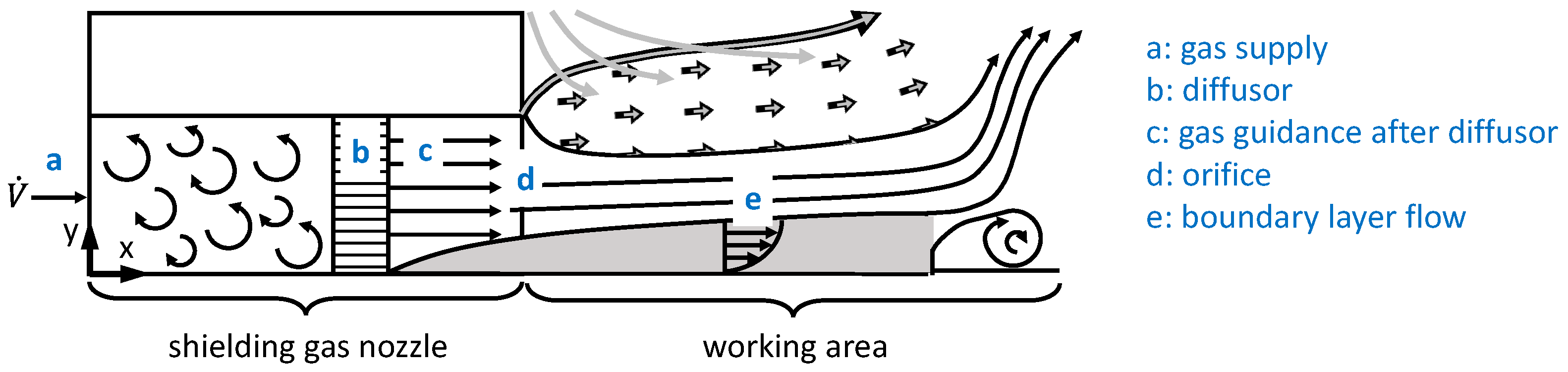
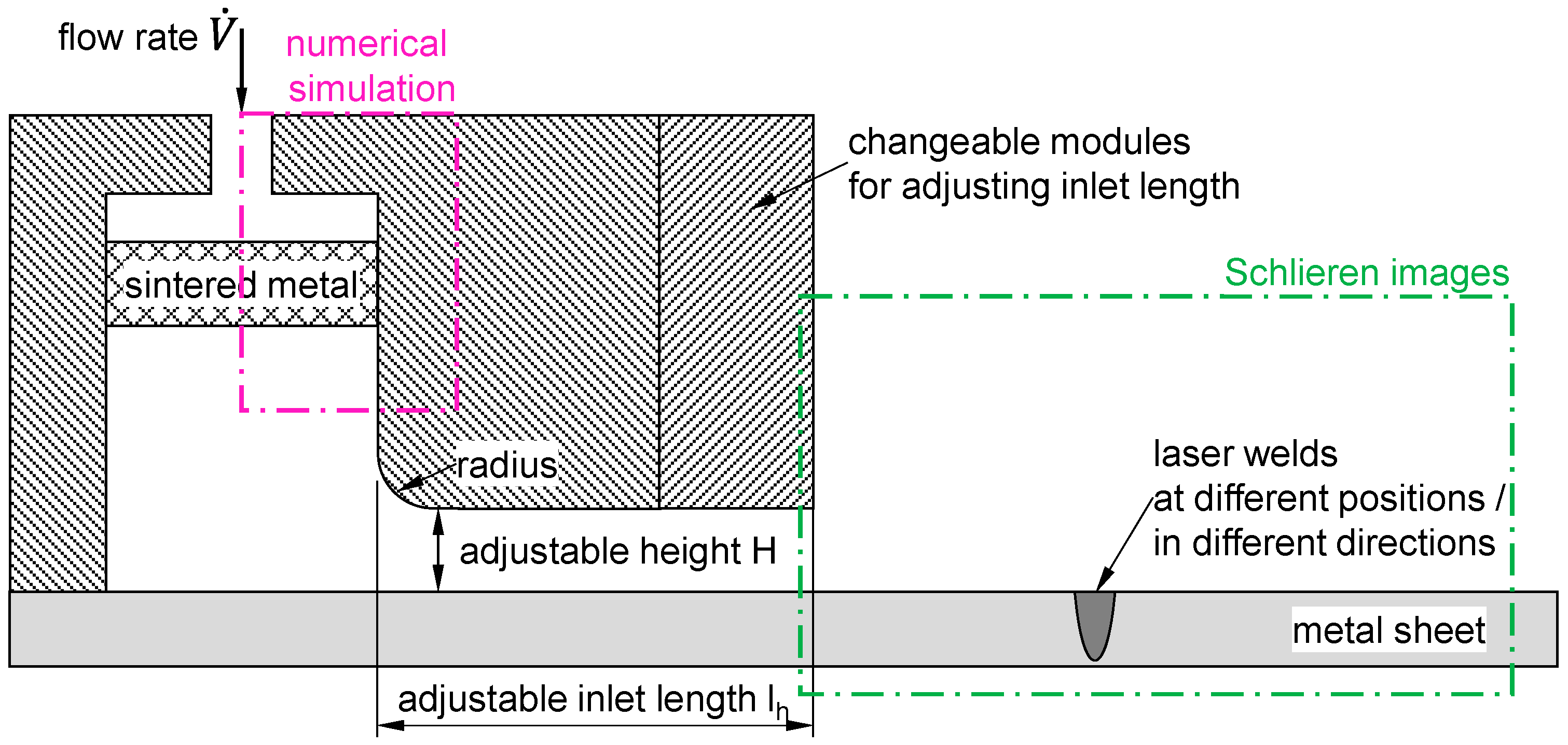
2.1. Design of Shielding Gas Nozzle

Figure 2 depicts the developed modular flat jet nozzle. The design allows the manipulation of flow conditions. The width b of the nozzle outlet is set to 50 mm to minimize the influence of the lateral shear layer on the shielding gas coverage (see Section 1) for typical weld lengths in remote welding up to 40 mm. The nozzle outlet height H is adjustable in steps of 1 mm up to 5 mm. The volume flow rate V ˙ can be adjusted freely up to 32 L/min. The gas inlet is followed by a sintered metal working as part of the diffusor to reduce flow velocity and homogenize the gas flow. Different materials and approaches were considered to obtain a nearly uniform flow velocity behind the sintered metal. The considerations were carried out by means of numerical simulation in Comsol Multiphysics 5.6 and based on Brinkman equations and Forchheimer correction for flow through porous media [28]. The area simulated in 2D is also shown in Figure 2. The flow is described by stationary and incompressible Navier–Stokes equations; walls without slip, inlet velocity of the shielding gas (Argon) and outlet as pressure without viscous stresses were considered as boundary conditions [28].
Two different sintered materials (see Table 1) and vanes according to [29] were considered as diffusor elements. Figure 3a shows the flow velocity within the diffusor for a maximum flow rate of 32 L/min. The porous materials were positioned 20 mm below the cross-section enlargement. The realization of a homogeneous velocity profile is clearly seen by means of the false color plot. Two different sintered materials were compared by the velocity along the cutline below the sintered metal in Figure 3b. Additionally, the result of simulated vanes according to [29] was added. The sintered metals achieve a better homogenization of the flow than vanes in a much more compact space. The homogenization of velocity flow is improved as the flowability decreases, as seen by the advantageous results of sintered metal 2 compared to sintered metal 1. This material reaches a uniform velocity distribution even in the center of the material (at diffusor width 0 in the simulation), where the highest flow velocity prevails at the inlet. Sintered metal 2 was chosen as a porous material in the diffusor (sintered bronze CA100 by GGT Gleit-Technik AG). Sufficient harmonization is provided by the presented velocity profiles to affect the flow before the gas leaves the nozzle through different inlet heights H and inlet lengths lh.
The inlet length lh can be varied from 50 mm to 140 mm. A radius of 3 mm ensures the transition of the flow cross-section to the adjustable height H without edges (see radius in Figure 2). The limitation of the inlet length is based on practical considerations, since even 140 mm is only achievable in exceptional cases with regard to the installation space in clamping devices. It can be assumed that the parabolic flow (PF) increases with the increasing inlet length but is not required to be complete (PF = 100%) for reaching a sufficient inert gas coverage, since the velocity at the wall is reduced faster than in the center of the channel due to the growing boundary layer. Figure 4a shows the velocity profile with increasing PF for a standardized coordinate, where 0 is the centerline of the channel and 1 the boundary. This outer region as shear layer is expected to be crucial for the mixing with the atmosphere. Within the bounds for the geometric parameters and the volume flow different flow regimes for the flat jet nozzle can be investigated by varying the height H, nozzle width b, inlet length lh and volume flow rate V ˙ . Nozzle height and width can be combined into the hydraulic equivalent diameter dgl (see Equation (2)).
d g l = 2 H b H + b
Figure 4b shows the possible working range of the designed flat jet nozzle and names the boundary conditions depending on mean spatial flow velocity um and equivalent diameter dgl. A turbulent flow at Re 3000 cannot be reached due to the maximum flow rate of 32 L/min is forming the main boundary. It should be noted that for high Re and high values of dgl, a fully developed parabolic flow cannot be reached (PF < 100%) due to the maximum inlet length lh of 140 mm. The maximum value of dgl is limited by the maximum gap height H of the nozzle of 5 mm.
The experiment was carried out mainly by a set of dimensionless numbers in order to reduce the number of variables. In addition to the reduced parameter space, the generalization of the results to similar but slightly different nozzle designs should be possible. The Reynolds number Re is of special interest because it allows, in addition to a combined consideration of variables, an estimate for the flow regime laminar/turbulent. Re is thereby varied by the hydraulic equivalent diameter dgl and mean spatial flow velocity um, resulting from the geometric quantities and the volume flow. Identical Re numbers are examined for different values of um and dgl depending on the different inlet lengths. It should be noted that a fully parabolic flow cannot be reached for large values of dgl (P < 100%), due to unpractical values for lh. Three different Re (150, 447, 1300) were considered in the investigations to address different flow conditions of the flat jet nozzle.
In addition to Re, dimensionless numbers were calculated according to [30] considering the parameters shown in Table 2. The parameters were selected to take all the relevant mechanisms into account. Six dimensionless numbers could be determined, including well-known quantities such as Re and Froude number. The dimensionless number shown in Equation (3) was utilized during the study in addition to Re, combining the inlet length and hydraulic equivalent diameter, i.e., solely geometric variables of nozzle design.
π = l h d g l

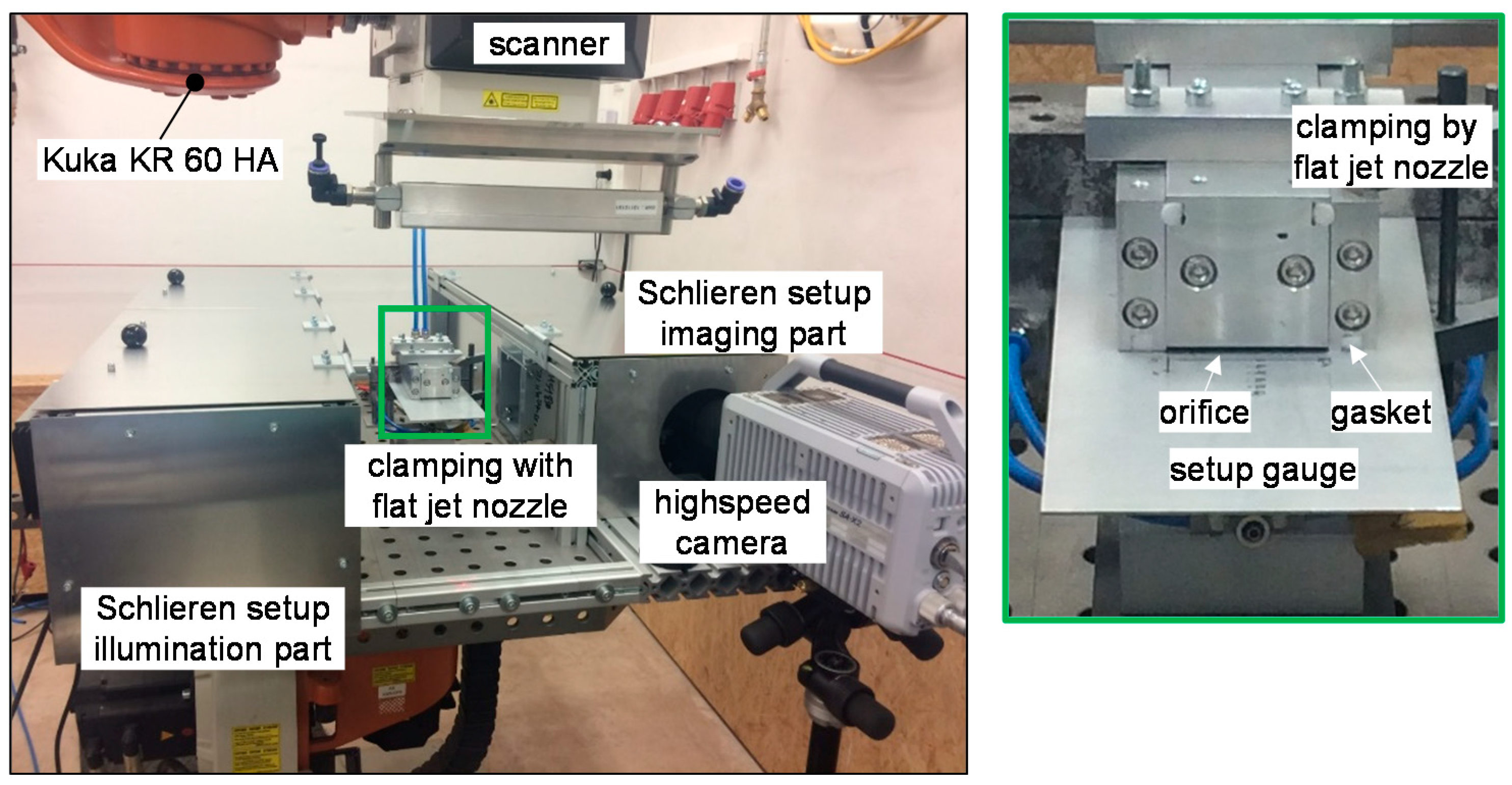
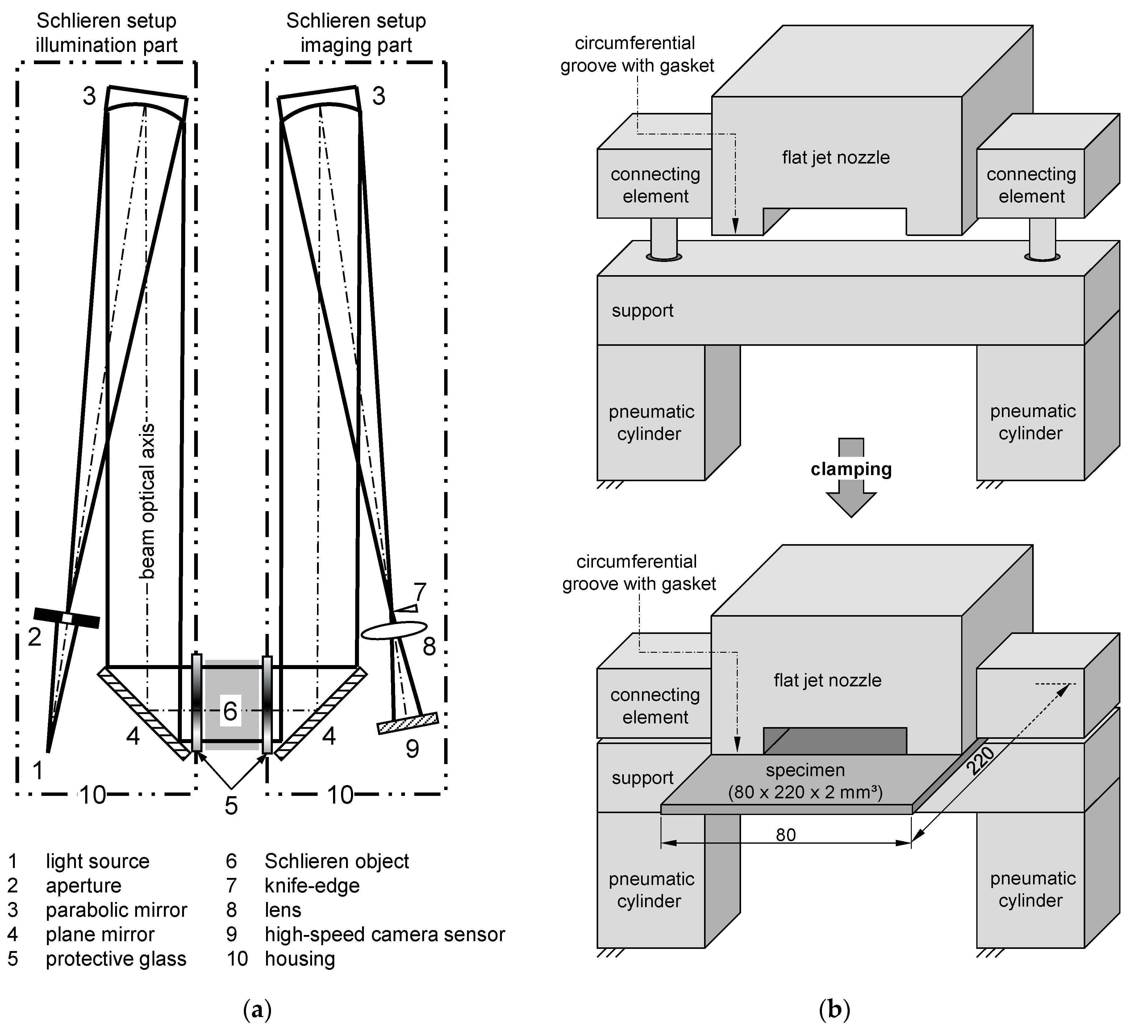
2.2. Experimental Setup

The experiments were carried out using a Trumpf TruDisk 5000.75 disc laser with a maximum output power of 5000 W and an optical fiber with a diameter of 75 µm. A laser scanning module (Scanlab IntelliWeld 30 FC) was mounted on a six-axis robot (Kuka KR 60 HA) and controlled by a Blackbird RobotSyncUnit SCU-2. The welding process was performed on high-alloy steel sheets of AISI 304 with a thickness of 2 mm. The width of the sheets was 80 mm. The length of the sheets was set to 220 mm to be able to implement different inlet lengths of the flat jet nozzle with the same sheet geometry. This alloy is known for its high susceptibility to form-annealing colors and is, therefore, a good choice to identify the oxygen contamination of the shielding gas atmosphere. To increase complexity stepwise, the experiments were carried out on spot welds and line welds. Heat conduction welding and deep penetration welding were considered as processes to determine the effects of contour, temperature and escaping metal vapor from the keyhole. The experiments were carried out as bead on plate welds with partial penetration because the shielding gas supply is considered on the top side of the weld in this study. Table 3 presents an overview of the parameters used.
High-speed Schlieren imaging is based on the density gradient normal to the optical path within the optical path and was used for visualizing the flow pattern between Argon and ambient atmosphere. The area analyzed by Schlieren imaging is depicted in Figure 2. Further details on measurement principle were provided in [31]. Schlieren imaging was performed with and without laser welding processes at 10,000 Hz utilizing a Photron SA-X2 high-speed camera. Further information regarding the setup is given in Appendix A.
Flow velocity was measured by constant temperature anemometry using a hot-wire anemometer Dantec StreamLine 90N10 with sensor Probe Type 55PH. The sensor could not be calibrated for Argon which is why measurements were carried out with air. Comparability to shielding gas Argon was achieved by setting identical Reynolds numbers Re. The measurement frequency was set to 1 kHz and the measurement time to 10 s to evaluate the mean flow velocity u ¯ over time. An evaluation was carried out over the nozzle width and along the outflow direction. The high-resolution signal also allows the turbulence intensity Tu to be determined (see Equation (4)), where uRMS is the standard deviation and u ¯ is the mean velocity [32]. The degree of turbulence can serve as a measure of the quality of a disturbance-free laminar flow. It should be noted that purely laminar flows are almost impossible to realize in practice, which is why values for Tu smaller than 1–2% are considered as low in turbulence [33].
T u = u R M S u ¯

3. Results and Discussion

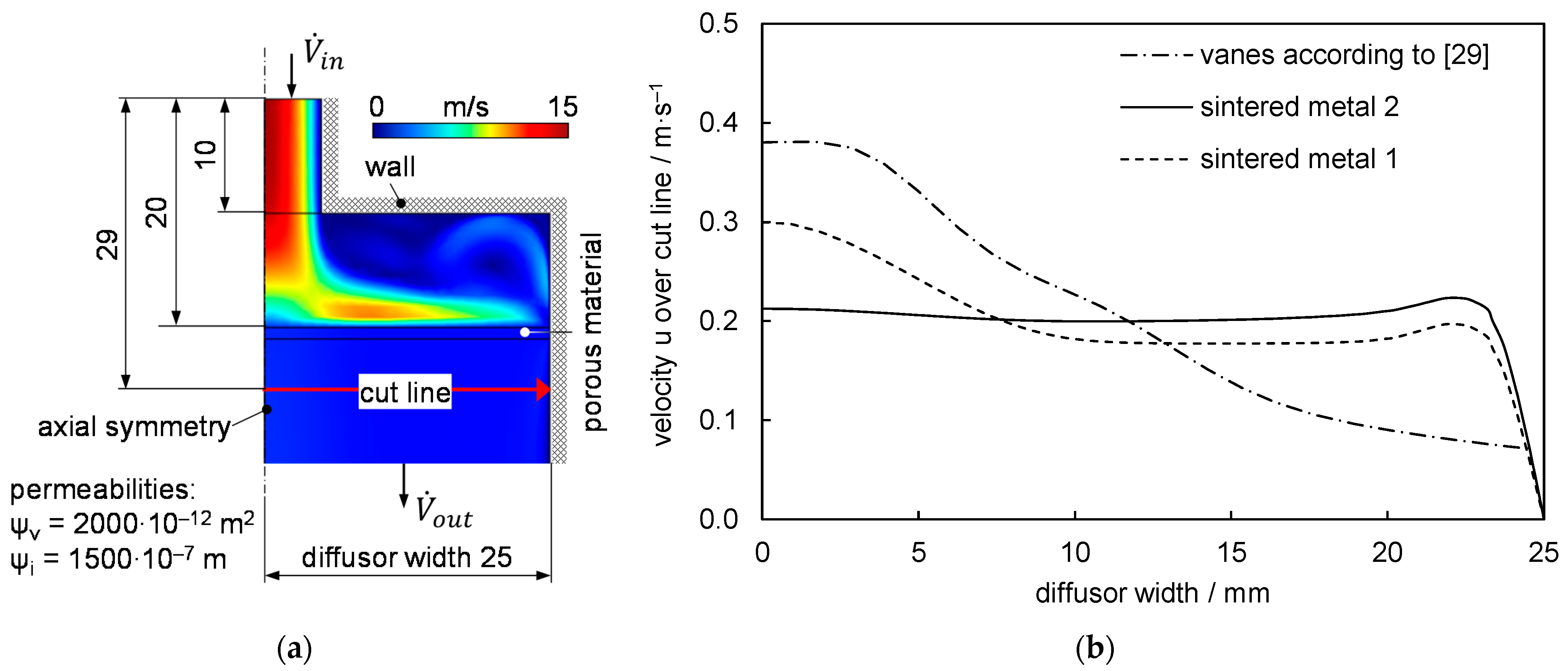
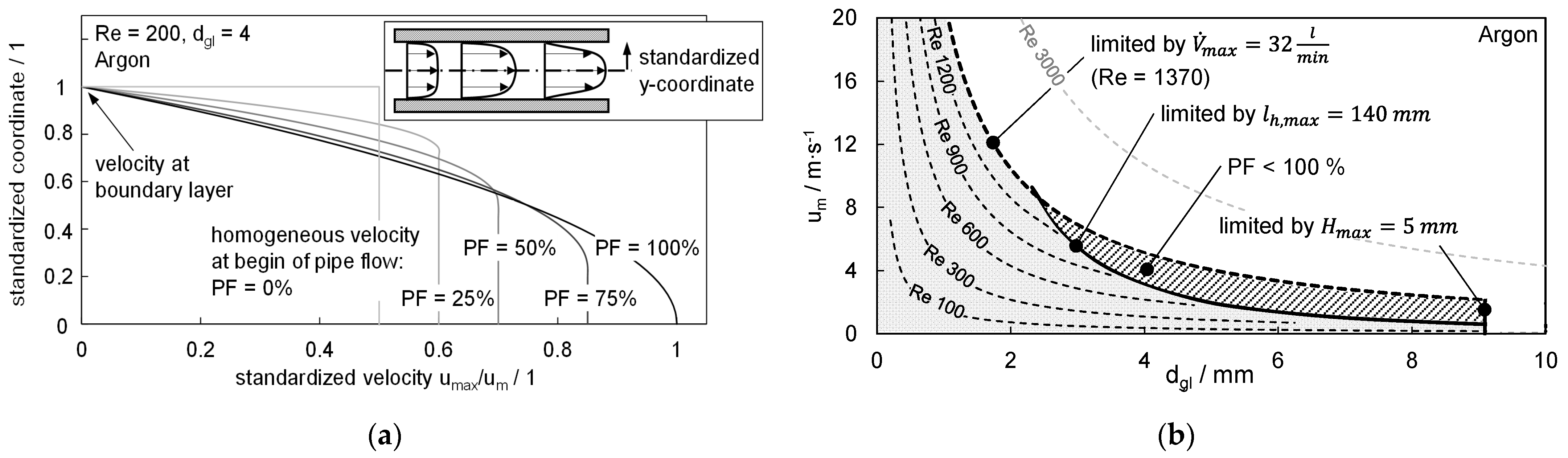
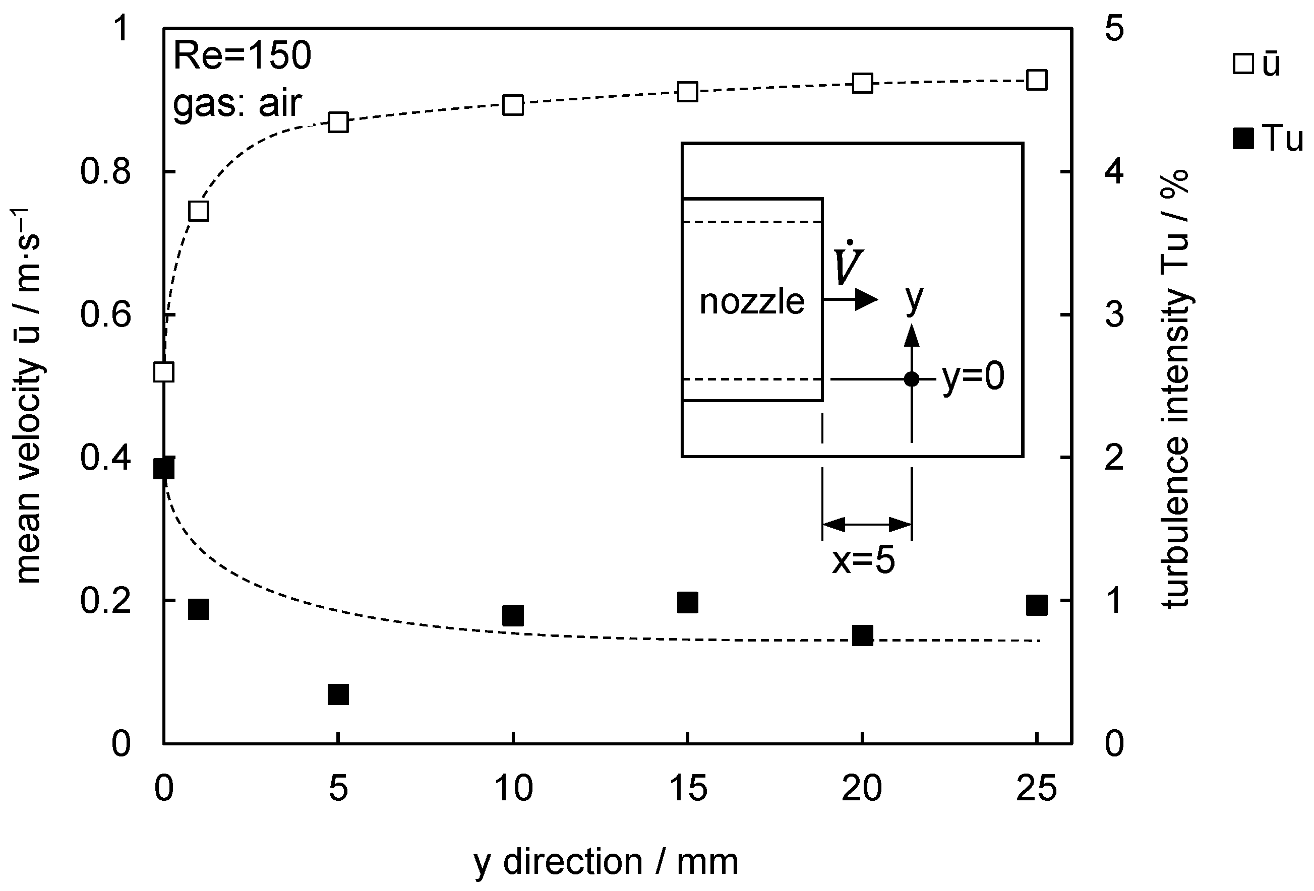
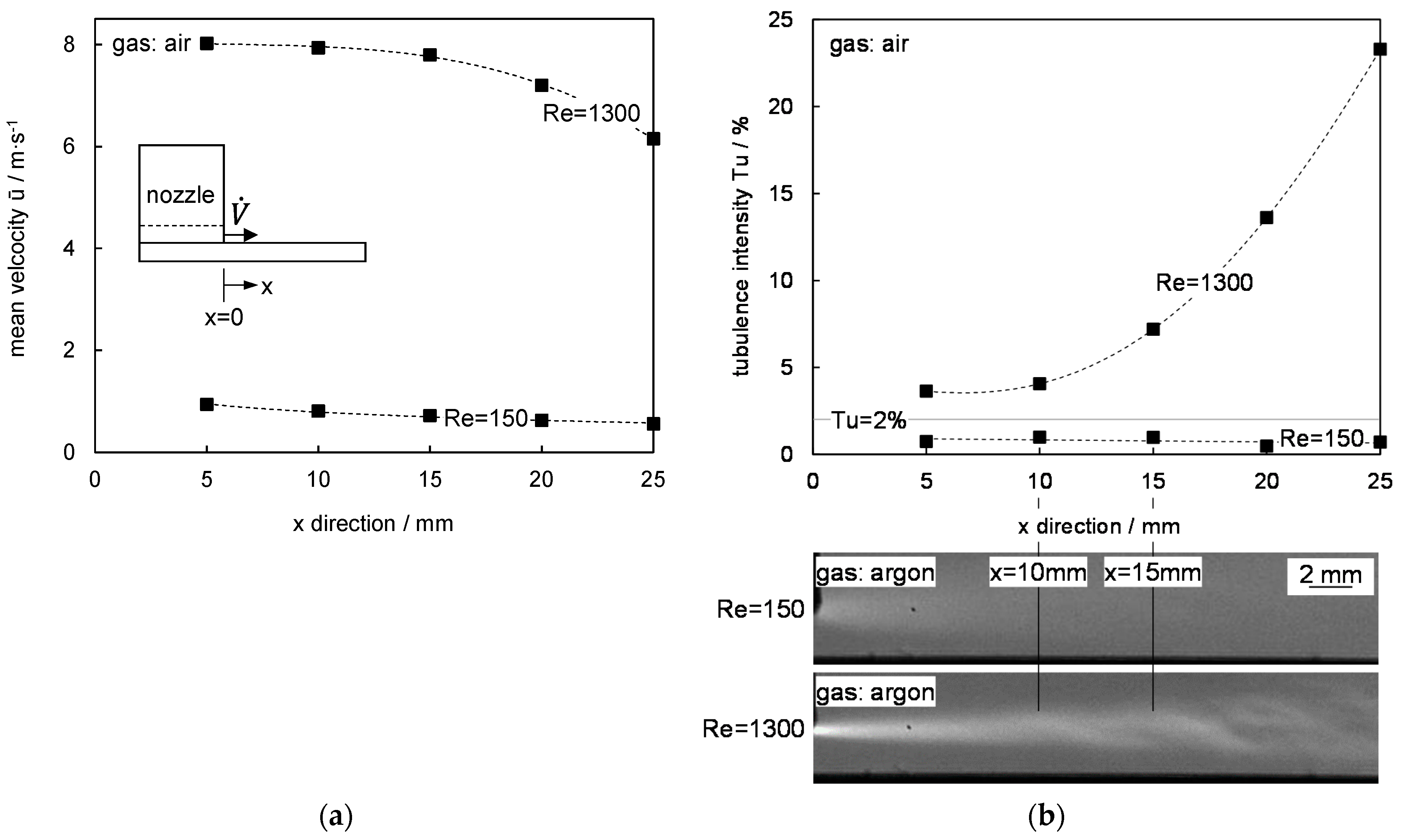
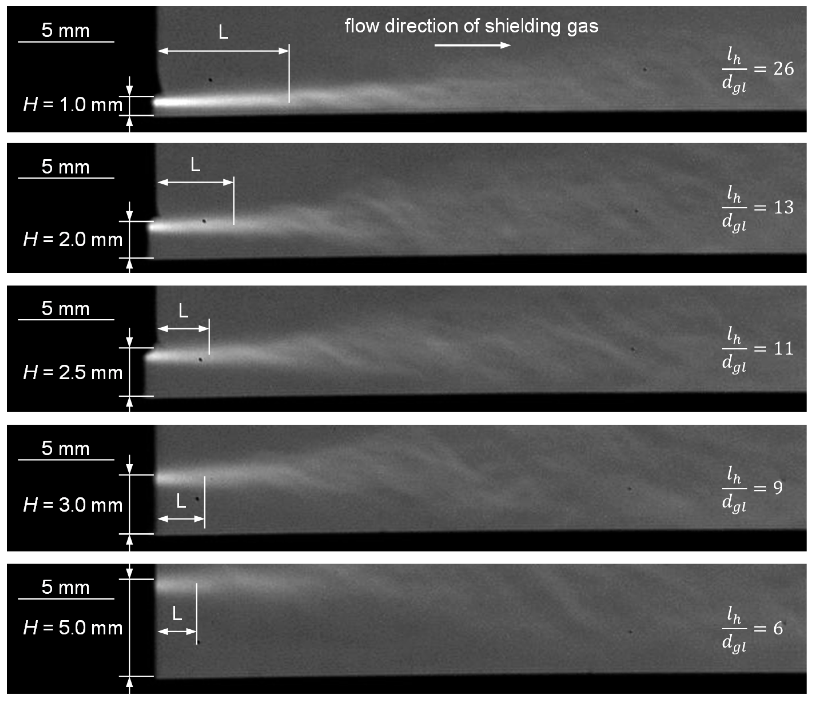
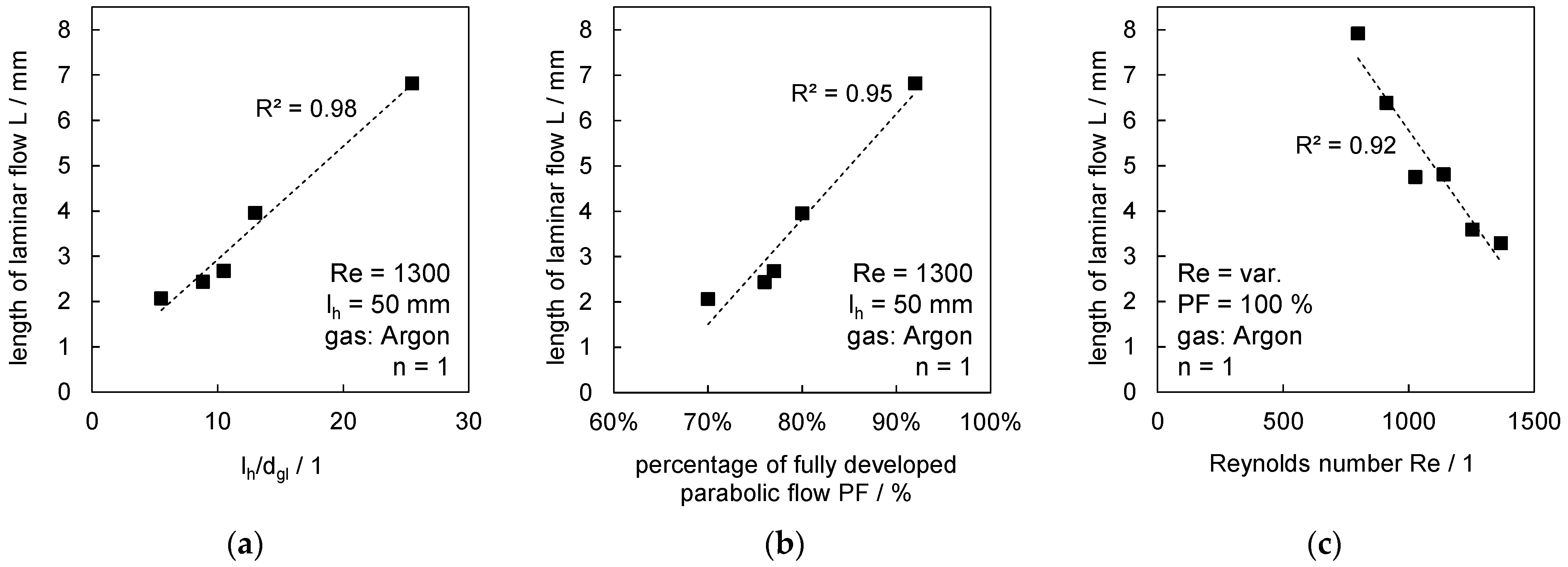
3.1. Description of Nozzle and Flow Properties

The achieved properties of the designed flat jet nozzle are described first. The mean velocity u ¯ was measured by constant temperature anemometry for minimum and maximum Re of 150 and 1300 over time (see Figure 5a). Both Re showed different velocities, i.e., 8.0 m/s for 1300 and 0.9 m/s for 150. However, a decrease in mean velocity u ¯ with increasing distance from the orifice was determined for both Re. Momentum transfer to ambient air, wall friction and internal fluid friction may have caused this effect. The deceleration of the gas flow with increasing distance could be relevant for shielding gas applications, since contaminations caused by the welding process and associated turbulences are transported away more slowly and the risk of oxidation may increase. Large distances between the welding process and the orifice may be disadvantageous even for laminar shielding gas flows because further transport phenomena are present, e.g., diffusion.
A consideration of the turbulence intensity in Figure 5b provides further information. For Re 150, the turbulence intensity is less than 2%, i.e., laminar flow can be assumed. A significant change in Tu over the 25 mm considered could not be detected, i.e., no transition from laminar to turbulent flow was seen. For Re 1300, Tu is already 4% directly at the orifice, which reflects a slightly turbulent flow already in this area. The turbulence intensity increases strongly after approximately 10 mm and reaches 10% after 17.5 mm, i.e., the turbulences increased with rising distance. Since Argon and air feature different but comparable properties (difference in density approx. 30%, difference in dynamic viscosity approx. 19%), Schlieren images of Argon are compared at identical Re. No laminar-turbulent transition is discernible for Re 150 as seen in the measurements for air. For Re 1300, a strong change to turbulent flow due to mixing with air is evident between 10 and 15 mm.
Another interesting aspect discernable from Figure 5b is a small concentration gradient right from the moment the wall jet leaves the orifice. With respect to diffusion time for any given cross-section moving along the surface the lower velocity might allow gas molecules to travel further into the two zones. The increased effect of diffusion could be the reason for a smaller gradient in case of Re = 150 and henceforth lead to less contrast in the Schlieren image.
Figure 6 depicts the mean velocity depending on the nozzle width for Re 150. The velocity is almost constant over the width of the nozzle. However, the large difference in velocity between shielding gas and stationary atmosphere causes a shear layer at y = 0, resulting in a reduced velocity, but limited to a few millimeters in width. The turbulence intensity measured reaches its maximum of 2% in the shear layer, i.e., a laminar flow is reached over the nozzle width for Re 150. It can be stated that laminar or slightly turbulent flows can be set with the nozzle and a good agreement between measurements in air as well as Schlieren recordings in Argon can be observed. The laminar length of the shear layer in Schlieren images is well reflected, which is why it can be used for quantifying the length of the laminar flow.
Figure 7 shows the length of the laminar flow depending on the height H of the nozzle for a constant inlet length of 50 mm and a constant Re of 1300. Since small Tu are reached in this area, the length of the laminar flow L is defined as the length until turbulences appear within the shear layer in the transition area shielding gas-atmosphere.
It should be noted that the brighter the area in the Schlieren images, the higher the density gradient at this position. Close behind the nozzle, a small area of the shielding gas is contaminated with atmosphere. With increasing outflow length, this area grows and the contrast decreases. The flow is in a quasi-stationary state, only the formation of turbulent structures causes time-dependent fluctuations. In the transition region from laminar to turbulent flow, a continuous change between both conditions occurs. This intermittency of turbulence is typical for the transition region [21]. The chosen procedure (lh = const., H = var.) also varies the ratio between lh to dgl (see Equation (4)). Therefore, different heights H also provide information on the effect of the reached parabolic flow. The measured length of the laminar flow is indicated as L in every picture and decreases for increasing heights H because a less parabolic velocity profile is achieved based on the same inlet length. At the same time, with increasing height H, the area covered by shielding gas increases before turbulences reach the metal surface—even if the length of laminar flow is lower.
Figure 8a compares the measured laminar length L with the ratio of lh to dgl. As qualitatively seen from the Schlieren images, the length of laminar flow increases with increasing lh/dgl. L reaches maximum values of approx. 7 mm, i.e., it seems unreasonable that laminar shielding gas coverage can be achieved for longer welds or larger distances to the nozzle in practical set-ups. Figure 8b depicts the correlation of L with the percentage of fully developed parabolic flow (PF) based on the same data set. PF = 100% is achieved when umax reaches twice the mean velocity u ¯ (umax = 2· u ¯ ) for the channel flow. It is observed that the length of laminar flow thus also depends on the inlet length lh. The reason is a reduced velocity between shielding gas and air in the shear layer for increasing PF after the fluid leaves the nozzle. Due to the fact that PF = 100% is advantageous, further investigations were carried out in this respect for different Re. Figure 8c shows the relationship for experiments carried out at PF = 100%: L decreases with increasing Re, even if a fully developed parabolic flow is present. The reason is again postulated to be increased velocities of the flow for higher Re that causes a transition from laminar to turbulent flow more rapidly. For the sake of simplicity, a linear relationship was assumed for the relationships found. This reflects the behavior well due to the coefficients of determination of 0.92 to 0.98 presented in Figure 8a–c.

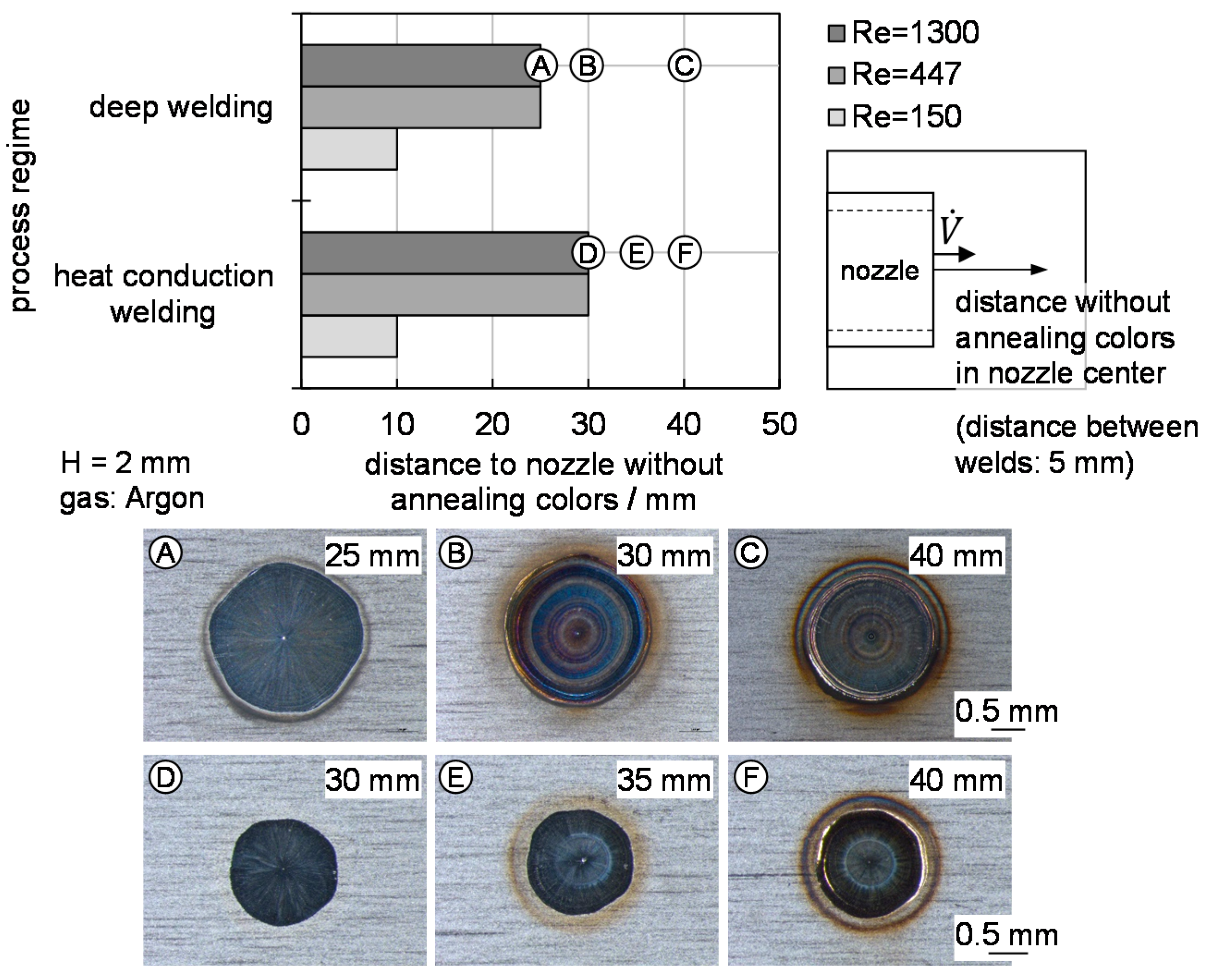
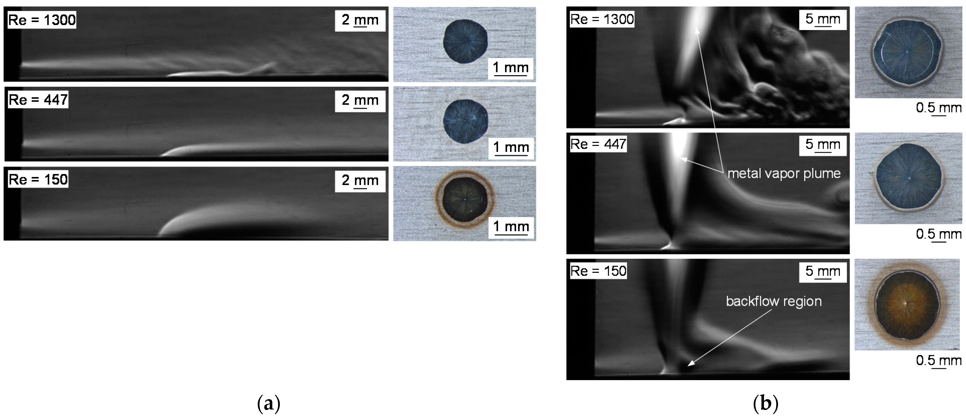
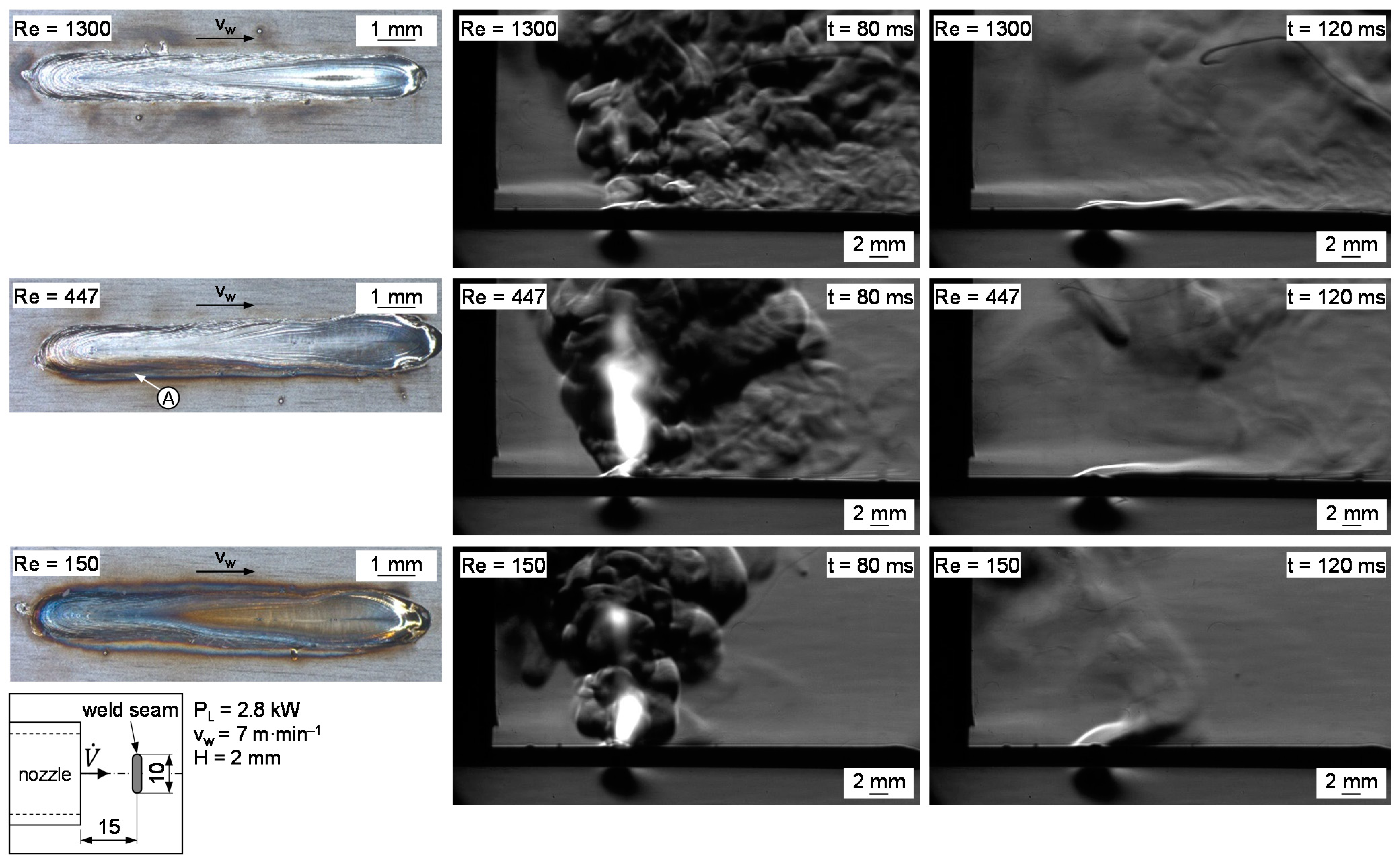
3.2. Characterization of Shielding Gas Coverage Depending on Process Regime and Re

Spot welds were performed for different welding regimes (heat conduction welding, deep penetration welding) and the parameters of the shielding gas supply. In addition to the findings of the nozzle in Section 3.1, the temperature of the molten pool and the metal vapor plume can affect the shielding gas coverage. It should be noted that a height H of 2 mm and the maximum inlet length lh of 140 mm were chosen to investigate general interrelationships. The distance between the orifice and the spot welds was varied in steps of 5 mm and evaluated regarding the presence of annealing colors. Figure 9 shows the results for both welding regimes depending on Re = 150, 447, 1300. Thereby, heat conduction welding shows the influence of temperature, while deep penetration welding extends this to the effect of metal vapor.
The best shielding gas coverage was reached at larger Re of 447 and 1300. In deep penetration welding, annealing color free welds were reached for distances up to 25 mm. For distances of 30 or 40 mm, annealing colors increased (see Ⓐ–Ⓒ) due to the increased mixing between the shielding gas and the ambient atmosphere. Heat conduction welding showed that longer distances of sufficient shielding gas coverage were reached at large Re in comparison to deep penetration welding. Gradually increasing tarnish colors were determined with increasing distance to the nozzle. While Ⓓ was tarnish-free, the annealing colors increased from Ⓔ and Ⓕ due to the heating of the shielding gas and the increasing intermixing because of buoyancy. The higher distances without tarnish compared to deep penetration welding can be explained by the absence of a metal vapor plume. Metal vapor escaped from the keyhole at high temperatures and high velocities during deep penetration welding that led to additional disturbances of the shielding gas coverage.
For Re = 150, the area of sufficiently supplied shielding gas was reduced significantly down to 10 mm for both welding regimes, i.e., minor disturbances hindered the shielding gas coverage for small Re.
Figure 10 shows the corresponding Schlieren images for both process regimes at a distance of 20 mm between weld and nozzle. The effect of increasing Re was well illustrated by the example of heat conduction welding (Figure 10a). The temperature of the molten pool caused heating of the shielding gas and, thus, buoyancy, which can cause suction. Tarnish forms if insufficient shielding gas is supplied. The height of the buoyant plume can be traced in the Schlieren images and is strongly limited for high Re = 1300. Even if a laminar-turbulent transition occurred, as was clearly visible for Re = 1300, it did not hinder the shielding gas coverage. The turbulences started at the shear layer to the ambient atmosphere, but obviously did not reach the melt pool surface at this position. If the kinetic energy of the shielding gas is insufficient, the buoyancy leads to sucking in atmosphere, as is visible in the annealing colors for Re = 150. The heat transfer to the shielding gas and the resulting buoyancy might be another factor, which could be related to the kinetic energy of the shielding gas in future investigations. This implies that an extended set of dimensionless parameters is necessary to capture the effects of changing Froude numbers through heating of the shielding gas at the hot metal surface.
The situation was comparable for deep penetration welding (Figure 10b), where metal vapor caused additional disturbances. An insufficient gas flow contributed to suction again and occurred behind the weld seam (as viewed from inflow direction) and thus to mixing with the ambient atmosphere. Stronger turbulences were present behind the weld at higher Re but did not have a detrimental effect on the shielding gas coverage at the processing zone. For the line welds, the effect is discussed again in Section 3.3. A backflow region or suction of ambient atmosphere was present for Re = 150, leading to annealing colors. It should be noted that the inclination of the metal vapor plume, recognizable as a bright cone, was affected by the inert gas flow only for very high Re, visible at Re = 1300, compared to the other images shown.
The previous considerations were carried out for a constant height, H = 2 mm. The results shown in Section 3.1 and Figure 7 suggested the beneficial effect of increasing values of H on shielding gas coverage. Based on this assumption, H was varied in three steps, from 1 to 5 mm, while Re was kept constant at 447. Figure 11a shows the effect of the gap height H for both welding regimes. It was confirmed that an increasing height H was advantageous for the shielding gas coverage. A sufficient coverage was determined for gap heights of 3 and 5 mm even beyond 45 mm, i.e., the entire distance investigated was successfully served with inert gas for both process regimes. Only 10 or 15 mm were safely covered for H = 1 mm due to the reasons mentioned before. The Schlieren images in Figure 11b illustrate the effect of different gap heights H at constant Re. The dashed line visualizes the area approximately covered with shielding gas. A reliable shielding gas coverage at the sheet surface was achieved due to the large gap. Despite the fact that mixing started in the shear layer and increased over distance, a sufficiently high gap ensured that the metal surface was protected from the ambient atmosphere sufficiently and avoided annealing colors.

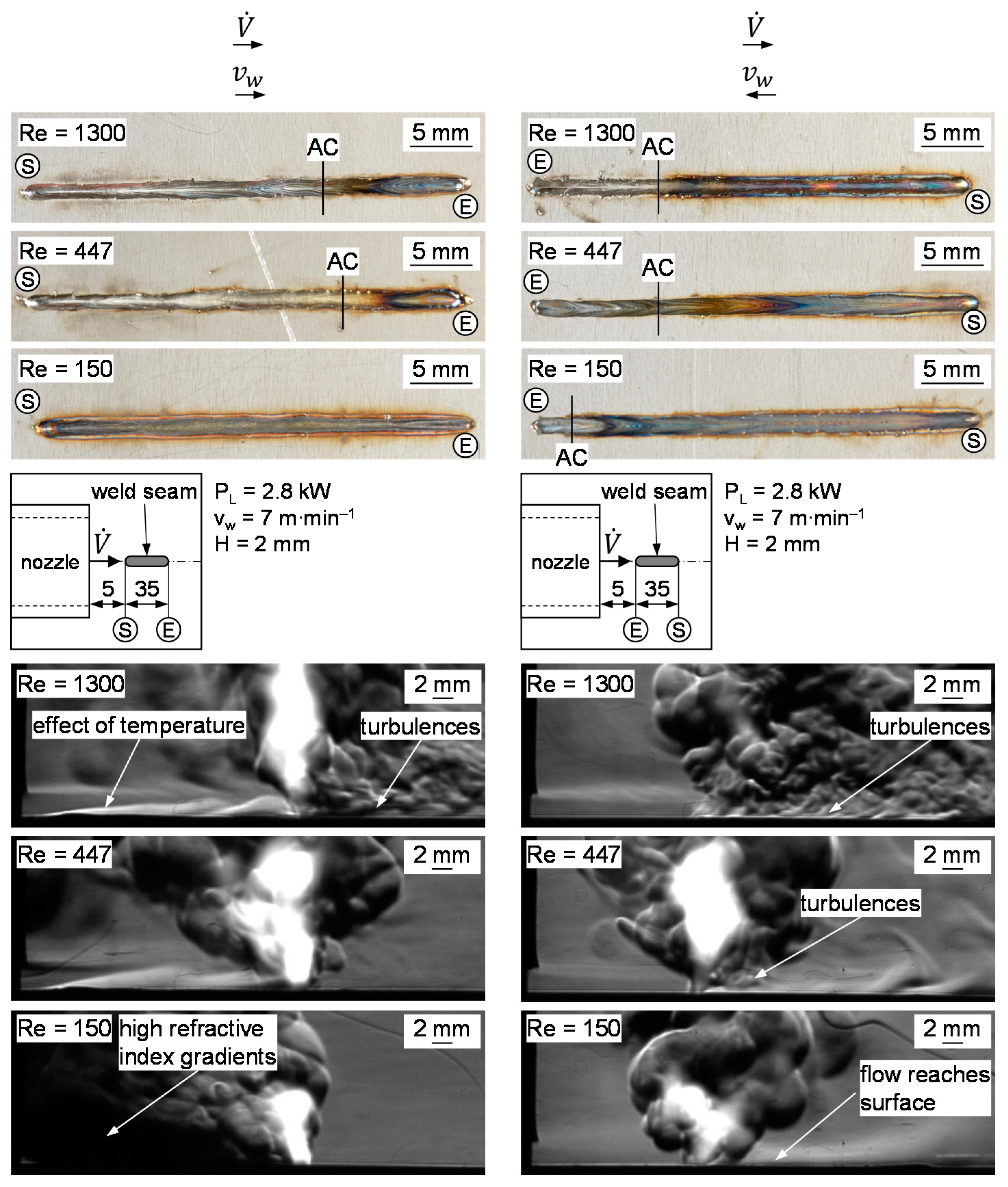
3.3. Interaction between Welding Direction and Shielding Gas Coverage

Further investigations were carried out on the effect of the welding direction on the shielding gas coverage based on the findings of the spot welds. Based on the three selected Re, Figure 12 shows the behavior of the line-shaped stitch welds carried out perpendicular to the shielding gas flow. The formation of annealing colors was avoided for Re = 1300. Again, turbulences were visible in the Schlieren images during the process (t = 80 ms), but the metal surface was covered reliably. The interaction with the hot weld was clearly visible after the process (t = 120 ms) and results comparable to the heat conduction welds were obtained. A reliable gas coverage was observed for Re = 1300, despite the turbulence of the shear layer. Tarnishing occurred for Re of 150 and 447. It can be assumed that the overlap Ⓐ at the beginning of the weld seam supported a detachment of the flow for Re = 447, while the end of the weld appeared flatter and safely covered. Sufficient shielding gas coverage was not achieved at any point for Re = 150. Even after the process (t = 120 ms), a strong effect of buoyancy and backflow areas was visible.
Figure 13 shows the results for the stitch welds, welded with or opposite to the flow direction of the shielding gas. Ⓢ marks the starting point and Ⓔ the end point of each weld. If the welding direction and flow direction were identical, tarnish did not occur for Re 447 and 1300 for 20 mm or beyond. Beyond this distance, it was no longer possible to reliably cover the weld seam, i.e., the atmosphere reached the surface due to turbulence. A longer distance was covered at a Re of 447 compared to 1300, which can be explained by the reduced turbulence behind the seam based on the Schlieren images. This can be seen from the onset of tarnishing marked by AC in Figure 13. Even if the onset of tarnishing is sometimes hard to discern, it is clear from the coloring that the oxygen content downstream of AC is much higher for Re = 1300 compared to Re = 447. This is visible by the seam going from metallic blank to dark grey much more rapidly for Re = 1300. The gas had been seen rising above the hot weld in both cases before the interaction zone of the laser beam was reached. No sufficient coverage was achieved for Re = 150 as the disturbances from the process exerted a great influence on the shielding gas flow. The Schlieren images showed a high refractive index gradient in the area between the nozzles and the seam, which is why it appears black and it was not possible to provide a statement as to the mechanisms in this area due to the high presence of ambient atmosphere in this region. However, a transport of gas beyond the process zone was not detectable, in contrast with the Re of 447 and 1300.
When the welding direction and flow direction were opposed, generally, shorter areas without tarnishing were found compared to the reversed welding direction. Turbulence occurred behind the processing zone for Re of 447 and 1300; the flow contaminated with atmosphere reached the metal surface and caused annealing colors. This area was identified as critical, i.e., the contamination with atmosphere occurred in the area of already welded material and reacted with the oxygen from the environment due to its increased temperature. The flow also reached the surface at a certain distance behind the laser beam for Re of 150, which explained why a short area without tarnish was recognizable in the top view at the end of the seam.
This illustrated that the flow direction had a significant influence on the achievable shielding gas coverage. Contrary to the assumptions of [9], no positive effect of opposite welding and shielding gas flow direction was determined.

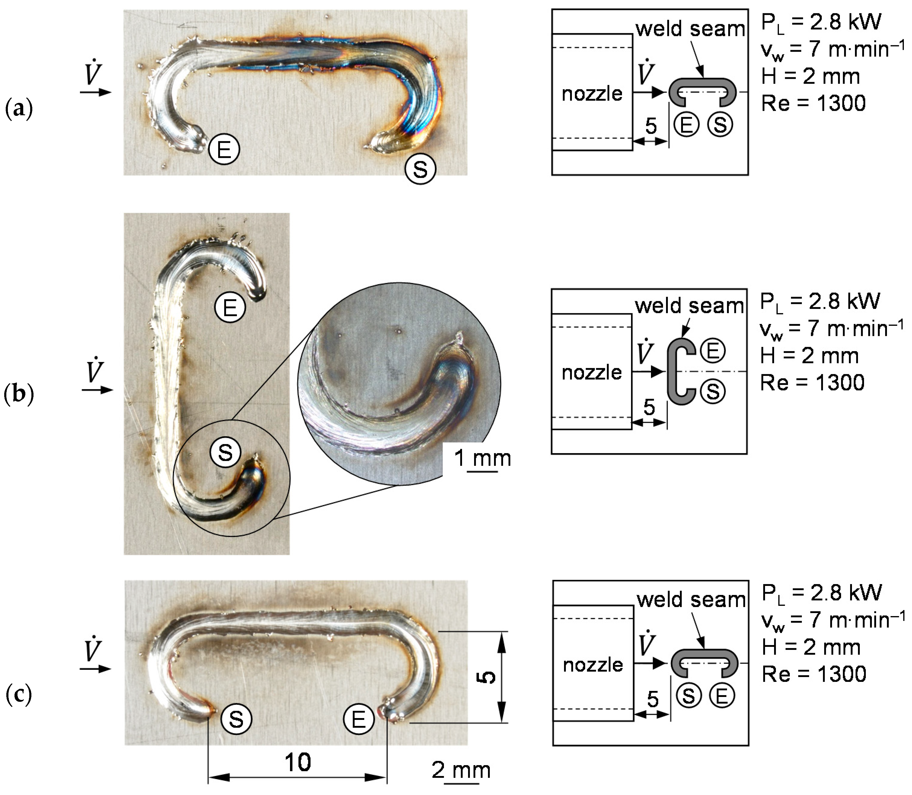
3.4. Effect of Complex Weld Seam Shapes

The findings were applied to complex weld geometries. C-shaped welds that include several changes of direction in a single weld seam were used as an example and Figure 14a–c show the welds investigated. The gas flow direction was always from the left to the right, and the start and end positions of the weld are marked with Ⓢ and Ⓔ, respectively. The interaction zone between the laser beam and the workpiece should always be in front of the direction of flow to ensure that turbulences, caused by the interaction between shielding gas, process zone and atmosphere, do not reach the hot weld metal.
If the start of the weld was opposite to the direction of flow, the expected tarnishing colors occurred due to the turbulence generated (Figure 14a). For a welding direction mainly perpendicular to the inflow direction, tarnish was avoided over large areas if the turbulence occurred outside the weld. However, welding the radius after the start (in the flow direction of the shielding gas) caused turbulences and resulted in a tarnished area around Ⓢ, as depicted in Figure 14b. By contrast, a tarnish-free seam was produced if the seam geometry, welding direction and inflow direction were correctly arranged (Figure 14c).

4. Conclusions

In this study, a flat jet nozzle was designed and utilized to carry out trials on shielding gas coverage in remote laser beam welding. The remote laser welding process motivated the use of a stationary shielding gas nozzle. The nozzle design and working range were described based on geometrical parameters and flow parameters. Based on different Re (150, 447, 1300), the shielding gas flow was characterized using constant temperature anemometry and high-speed Schlieren imaging. The interactions between the Reynolds number Re, nozzle outlet height H, inlet length lh and hydraulic equivalent diameter dgl were identified and allowed the realization of a sufficient shielding gas coverage. Higher Re and increasing H led to a faster transition from laminar to turbulent flow. By contrast, rising ratios lh/dgl and, thus, a greater number of parabolic velocity profiles, led to an increase in the length of the laminar flow. The effect of heat conduction welding and deep penetration welding was considered by spot welds and stitch welds to separate the effects of temperature and metal vapor. It was shown for spot welds that metal vapor escaping from the keyhole can negatively affect shielding gas coverage due to disturbances, high temperatures and high velocities. In general, higher Re of 447 or 1300 compared to 150 proved to be beneficial. At the same time, shielding gas coverage was improved for higher values of H. Both aspects proved that a laminar flow did not necessarily need to be present for sufficient shielding gas coverage. The effect of the inflow direction of the shielding gas and welding direction was observed on the stitch welds. The simultaneous orientation of welding and flow direction is advantageous to ensure that turbulences behind the processing zone do not cause a contamination of the shielding gas with oxygen from the ambient atmosphere. It should further be noted that high Re = 1300 caused further turbulences that led to slightly increasing tarnish compared to Re = 447 for an identically arranged direction of shielding gas flow and welding speed. The transfer to a C-shaped weld seam geometry demonstrated the findings based on a complex weld seam geometry.

Author Contributions

Conceptualization, K.S., A.B. and J.P.B.; methodology, K.S. and A.B.; formal analysis, K.S. and A.B.; investigation, A.B.; writing—original draft preparation, K.S.; writing—review and editing, A.B. and J.P.B.; visualization, K.S. and A.B.; funding acquisition, K.S. and J.P.B. All authors have read and agreed to the published version of the manuscript.

Funding

This research was funded by the federal ministry of economic affairs and energy within the German Federation’s industrial research associations (AiF Arbeitsgemeinschaft industrieller Forschungsvereinigungen), via the research association of the German Welding Society DVS (Forschungsvereinigung Schweißen und verwandte Verfahren e.V. des DVS), based on a resolution of the German parliament, grant number 22010 BR.

Data Availability Statement

The data presented in this study are available on request from the corresponding author. The data are not publicly available.

Conflicts of Interest

The authors declare no conflict of interest.

Appendix A

A more detailed view of the experimental setup is provided in Figure A1. The Schlieren imaging setup was mounted to a welding table and the flat jet nozzle was positioned between the illumination part and the imaging part. A setup gauge was used for the alignment between the flat jet nozzle and the laser beam process. The scanner was positioned via the Kuka KR 60 HA. The high-speed camera was adjusted to the beam path of the Schlieren setup by means of a tripod.
Figure A1. Experimental setup with laser system, Schlieren setup and flat jet nozzle.
Jmmp 05 00139 g0a1
A z-type Schlieren setup was used during the experiments to minimize the space requirements of the setup due to the beam folding, as described in [31]. Figure A2a depicts the illumination part and the imaging part of the z-type Schlieren setup. A light source (1) with an aperture (2) is aligned to a parabolic mirror (3) that collimates the beam. A plane mirror (4) directs the beam through a protective glass (5) onto the laser beam process, acting as a Schlieren object (6). The beam is directed to the knife-edge (7) via another protective glass, plane mirror and parabolic mirror. A lens (8) focuses the beam onto the focal plane of the high-speed camera sensor (9). The imaging part and the illumination part are housed (10) due to the welding process emissions.
The setup allowed the clamping device to be positioned and the laser beam process to be performed between the illumination part and imaging part of the Schlieren setup. The flat jet nozzle was integrated into the clamping device to simplify the experimental procedure, as shown in Figure A2b. Two pneumatic cylinders were connected to the flat jet nozzle and performed the clamping together, with a support structure as a counter bearing. The single-sided clamping ensured high accessibility for the Schlieren imaging and simplified the execution of trials. The flat jet nozzle was sealed by a circumferential groove with a gasket. A material thickness of 2 mm is stiff enough to counteract the distortion of the short welds, which can be seen in the Schlieren images (e.g., Figure 12 and Figure 13 in Section 3.3) due to the constantly horizontal position of the metal sheet.
Figure A2. (a) z-type Schlieren setup used during the investigations; (b) schematic depiction of clamping device with flat jet nozzle and specimen.
Jmmp 05 00139 g0a2

References

  1. Kah, P.; Lu, J.; Martikainen, J.; Suoranta, R. Remote laser welding with high power fiber lasers. Sci. Res. Eng. 2013, 5, 700–706. [Google Scholar] [CrossRef] [Green Version]
  2. Thomy, C.; Schilf, M.; Seefeld, T.; Sepold, G.; Vollertsen, F. Distortion minimization in re-mote welding of steel. Adv. Mater. Res. 2005, 6–8, 217–224. [Google Scholar] [CrossRef]
  3. Kutsuna, M.; Yan, Q. Study on porosity formation in laser welds in aluminium alloys (Report 1): Effects of hydrogen and alloying elements. Weld. Int. 1998, 12, 937–949. [Google Scholar] [CrossRef]
  4. Linde, A.G. Scanner-Schweiß-Vorrichtung. Patent Application No. DE 102 18 296 A1, 24 April 2002. [Google Scholar]
  5. Linde, A.G. Scanner Welding or Soldering Machine has Optical System with Swiveling Mirror or Flexible Scanner Optics for Directing Laser Beam on to Zones to be Joined, Pipes Allowing Protective Gases or Mixtures to be Fed on to Zones to be Bonded. Patent Application No. DE 10 2006 021 622 A1, 9 May 2006. [Google Scholar]
  6. Walter, J.; Hennings, C.; Hustedt, M.; Kaierle, S.; Borkmann, M.; Mahrle, A. Efficiency enhancement during remote laser welding by means of optimized air flow control. In Proceedings of the 22nd Fachtagung “Lasermethoden in der Strömungsmesstechnik”, Karlsruhe, Germany, 9–11 September 2014; German Association for Laser Anemometry GALA e.V.: Karlsruhe, Germany, 2014; pp. 49-1–49-8. [Google Scholar]
  7. Walter, J.; Hennings, C.; Alexander, B.; Hustedt, M.; Kaierle, S.; Borkmann, M.; Mahrle, A. Optimized airflow control during remote laser welding. Part I: Experimental studies. In Proceedings of the 23rd Fachtagung “Lasermethoden in der Strömungsmesstechnik”, Dresden, Germany, 8–10 September 2015; German Association for Laser Anemometry GALA e.V.: Karlsruhe, Germany, 2015. [Google Scholar]
  8. Borkmann, M.; Mahrle, A.; Beyer, E.; Hennings, C.; Hustedt, M.; Walter, J.; Kaierle, S. Air flow control for processing stations of remote laser beam welding—Part 2: Simulations for system optimization. In Proceedings of the 24th Fachtagung “Experimentelle Strömungsmechanik”, Cottbus, Germany, 6–8 September 2016; German Association for Laser Anemometry GALA e.V.: Karlsruhe, Germany, 2016; pp. 22-1–22-8. [Google Scholar]
  9. Johnson Controls Technology Company. Method and Apparatus for Laser Welding. Patent Application No. US 2008/0296271 A1, 27 October 2005.
  10. Oefele, F. Remote-Laserstrahlschweißen mit brillanten Strahlquellen; Utz: München, Germany, 2013. [Google Scholar]
  11. Patschger, A.; Sahib, C.; Bergmann, J.; Bastick, A. Process optimization through adaptation of shielding gas selection and feeding during laser beam welding. Phys. Procedia 2012, 12, 46–55. [Google Scholar] [CrossRef] [Green Version]
  12. Oefele, F.; Musiol, J.; Zaeh, M. Influence of remote-laser-welding parameters for an 8 KW fibre laser on the seam quality of steels. In Proceedings of the Laser Materials Processing Conference ICALEO, Temecula, CA, USA, 20–23 October 2008; Paper 709. Laser Institute of America: Orlando, FL, USA, 2008. [Google Scholar]
  13. Seefeld, T.; Neumann, S. Abschlussbericht AiF 13.953/4 Schweißnahtqualität und Anwendungspotentiale beim Remote-Welding mit Hoher Leistung; Bremer Institut für angewandte Strahltechnik: Bremen, Germany, 2006. [Google Scholar]
  14. Herrmann, J. Prozessgase beim Laserschweißen. Kostenfaktor oder Garant für wirtschaftliche, stabile und hochwertige Schweißverbindungen. DVS-Berichte 2006, 241, 133–142. [Google Scholar]
  15. Kern, M. Gas- und Magnetofluiddynamische Maßnahmen zur Beeinflussung der Nahtqualität beim Laserstrahlschweißen; Teubner: Stuttgart, Germany, 1999. [Google Scholar]
  16. Tani, G.; Ascari, A.; Campana, G.; Fortunato, A. A study on shielding gas contamination in laser welding of non-ferrous alloys. Appl. Surf. Sci. 2007, 254, 904–907. [Google Scholar] [CrossRef]
  17. Schuhbauer, G.; Spangenberg, W. Effect of Screens in Wide-Angle Diffusers; NACA TR 949; National Bureau of Standards: Washington, DC, USA, 1948. [Google Scholar]
  18. EN ISO 4022: 2018 Permeable Sintered Metal Materials—Determination of Fluid Permeability. Available online: https://www.iso.org/standard/72838.html (accessed on 12 November 2021).
  19. Bajura, R.; Szewczyk, A. Experimental investigation of a laminar two-dimensional plane wall jet. Phys. Fluids 1970, 13, 1653–1664. [Google Scholar] [CrossRef]
  20. Bajura, R.; Catalano, M. Transition in a two-dimensional plane wall jet. J. Fluid Mech. 1975, 70, 773–799. [Google Scholar] [CrossRef]
  21. Schlichting, H.; Gersten, K. Grenzschicht-Theorie, 9th ed.; Springer: Berlin, Germany, 1997. [Google Scholar]
  22. Schiller, L. Die Entwicklung der laminaren geschwindigkeitsverteilung und ihre bedeutung für zähigkeitsmessungen. Z. Angew. Math. Mech. 1922, 2, 96–106. [Google Scholar] [CrossRef] [Green Version]
  23. Oertel, H.; Böhle, M.; Reviol, T. Strömungsmechanik, 7th ed.; Vieweg + Teubner: Wiesbaden, Germany, 2015. [Google Scholar]
  24. Gogineni, S.; Shih, C. Experimental investigation of the unsteady structure of a transitional plane wall jet. Exp. Fluids 1997, 23, 121–129. [Google Scholar] [CrossRef]
  25. Gersten, K.; Herwig, H. Strömungsmechanik Grundlagen der Impuls-, Wärme- und Stoffüber-Tragung aus Asymptotischer Sicht; Vieweg: Braunschweig, Germany, 1992. [Google Scholar]
  26. Chernorai, V.; Litvinenko, M.; Litvinenko, Y.; Kozlov, V.; Cherednichenko, E. Longitudinal structures in the near field of a plane wall jet. Thermophys. Aeromechanics 2007, 14, 515–523. [Google Scholar] [CrossRef]
  27. Comsol Multiphysics. CFD Module User’s Guide—Inlet Values for the Turbulence Length Scale and Turbulent Intensity; Comsol Multiphysics: Burlington, NJ, USA, 2018. [Google Scholar]
  28. Comsol Multiphysics. Porous Media Flow Module User’s Guide; Comsol Multiphysics: Burlington, NJ, USA, 2020. [Google Scholar]
  29. Cochran, D.; Kline, S. Use of Short Flat Vanes for Producing Efficient Wide-Angle Two Dimensional Subsonic Diffusers; NACA TN 4309; National Advisory Committee for Aeronautics: Washington, DC, USA, 1958.
  30. Szirtes, T.; Rózsa, P. Applied Dimensional Analysis and Modeling, 2nd ed.; Elsevier: Amsterdam, The Netherlands, 2007. [Google Scholar]
  31. Settles, G. Schlieren and Shadowgraph Techniques: Visualizing Phenomena in Transparent Media; Springer: Heidelberg, Germany, 2001. [Google Scholar]
  32. Dantec Dynamics. How to Measure Turbulence with Hot-Wire Anemometers—A Practical Guide; Dantec Dynamics: Copenhagen, Denmark, 2002. [Google Scholar]
  33. dos Santos, C.; Jabardo, P.; Cardoso, M.; Taira, N.; Pereira, M. Characterization of low turbulence wind tunnel. In Proceedings of the XVIII IMEKO World Congress, Rio de Janeiro, Brazil, 17–22 September 2006. [Google Scholar]
Figure 1. Model concept of fluid mechanics of shielding gas supply using the example of a flat jet nozzle.
Jmmp 05 00139 g001
Figure 2. Schematic cross-sectional view of shielding nozzle.
Jmmp 05 00139 g002
Figure 3. (a) magnitude of flow velocity for the sintered material (dimensions in mm); (b) effect of different diffusor designs on harmonization of flow velocity.
Jmmp 05 00139 g003
Figure 4. (a) Velocity distribution within the flat jet nozzle for different parabolic flow profiles from tophat (PF = 0%) up to completely parabolic flow (PF = 100%) (calculation according to [22]); (b) achievable Re and limits of the adjustable flat jet nozzle.
Jmmp 05 00139 g004
Figure 5. (a) Mean velocity of flow depending on distance to orifice (x = 0); (b) turbulence intensity depending on distance to orifice and related Schlieren images for Argon.
Jmmp 05 00139 g005
Figure 6. Mean velocity of flow over nozzle width.
Jmmp 05 00139 g006
Figure 7. Dependance of laminar flow length on adjustable heights H and ratio lh/dgl.
Jmmp 05 00139 g007
Figure 8. Length of laminar flow depending on: (a) lh/dgl; (b) percentage of fully developed parabolic flow; (c) Re.
Jmmp 05 00139 g008
Figure 9. Occurrence of annealing colors depending on distance to orifice for deep penetration welding and heat conduction welding.
Jmmp 05 00139 g009
Figure 10. Schlieren images at a distance to nozzle of 20 mm for different Re to consider the effect on shielding gas coverage for: (a) heat conduction welding; (b) deep penetration welding.
Jmmp 05 00139 g010
Figure 11. (a) Effect of gap height H on shielding gas coverage; (b) Schlieren images in heat conduction welding at different gap heights H.
Jmmp 05 00139 g011
Figure 12. Shielding gas coverage of stitch welds perpendicular to flow direction.
Jmmp 05 00139 g012
Figure 13. Effect of welding direction on shielding gas coverage and Schlieren images at weld seam center.
Jmmp 05 00139 g013
Figure 14. Tarnishing on C-shaped weld seams depending on welding direction: (a) weld direction opposite to flow direction; (b) weld direction perpendicular to flow direction; (c) weld direction equal to flow direction.
Jmmp 05 00139 g014
Table 1. Material properties of sintered metals.
MaterialCoefficient of Permeability
ψv/m2
Coefficient of Inertial
Permeability ψi/m
sintered metal 1200 × 10−12150 × 10−7
sintered metal 22000 × 10−121500 × 10−7
Table 2. Parameters considered for calculation of dimensionless numbers.
ParameterSymbol
dynamic viscosity shielding gasηs
dynamic viscosity airηa
density shielding gasρs
density airρa
inlet lengthlh
gravityg
length of laminar flowL
mean spatial flow velocity ū
hydraulic equivalent diameterdgl
Table 3. Welding parameters for heat conduction and deep penetration welding.
Weld
Geometry
Process RegimeLaser Beam Power PL/W Joining Time tL/ms
Welding Speed/m∙min−1
spot weldheat conduction welding80050 ms
deep penetration welding250050 ms
line welddeep penetration welding28007 m∙min−1
Publisher’s Note: MDPI stays neutral with regard to jurisdictional claims in published maps and institutional affiliations.

