Abstract
Despite decades of development, micro air vehicles (MAVs) still face challenges related to endurance. While solar power has been successfully implemented in larger aircraft as a clean and renewable source of energy, its adaptation to MAVs presents unique challenges due to payload constraints and complex surface geometries. To address this, this work proposes an automated algorithm for optimal solar panel arrangement on complex upper surfaces of the MAV. In addition to that, the aerodynamic performance is evaluated through computational fluid dynamics (CFD) simulations based on the Reynolds-Averaged Navier–Stokes (RANS) method. A multi-objective optimization approach simultaneously considers photovoltaic energy generation and aerodynamic efficiency. Wind tunnel validation and stability analysis of flight dynamics confirm the advantages of our optimized design. To our knowledge, this represents the first systematic framework for the energy–aerodynamic co-optimization of solar-powered MAVs (SMAVs). Flight tests of a -span tailless prototype demonstrate the practical feasibility of our approach with maximum solar cell deployment.
1. Introduction
Micro air vehicles (MAVs) are widely used in environmental monitoring and military reconnaissance due to their portability and agility [1]. However, most MAVs are constrained by limited onboard energy capacity and aerodynamics, resulting in short flight durations [2]. Large-scale solar-powered UAVs achieve significantly longer endurance by integrating solar cells [3], employing various methods to extend the endurance of flight [4,5]. They benefit from their high lift-to-drag ratios and reduced cruise power requirements. In recent years, diverse designs of solar-powered unmanned air vehicles (UAVs) have been proposed [6,7,8]. Years of research and flight tests have refined their design methodologies and optimization strategies [9,10]. Research on optimization design methods for solar-powered UAVs has evolved from early parametric modeling and energy balance design processes [11] to the current multidisciplinary design optimization framework [12]. Many studies decompose the design problem into multi-levels [13]. Then they convert it to a multi-objective optimization including aerodynamics, structure, and energy aspects. Although such methods are not uncommon, research on the integration of photovoltaic technology into miniaturized drones remains relatively scarce. The integration of solar technology into vertical take-off and landing (VTOL) aircraft represents a novel approach [14], enabling landing–recharging–relaunch cycles to achieve prolonged operation through multiple flight cycles [15]. Furthermore, miniaturization has become a significant trend [16,17]. Inspired by this, MAVs may also use solar energy to enhance endurance. Recent specifications of MAVs and small-sized solar-powered UAVs are summarized in Table 1.

Table 1.
Summary of MAVs and miniature size solar-powered aircraft.
Recent advancements have made solar-powered UAVs increasingly prevalent, aligning with sustainable development and clean-energy initiatives. However, current designs often treat solar energy as an additional payload rather than achieving optimal integration with aerodynamics. While solar integration has been attempted in flapping-wing and multirotor MAVs, challenges like aerodynamic efficiency and energy harvesting limitations keep these designs experimental. Fixed-wing MAVs offer more promise but face design constraints—their complex geometries and limited wing area hinder photovoltaic coverage. A key trade-off exists: maximizing solar energy collection favors large, flat surfaces, while aerodynamic efficiency requires slender, high-aspect-ratio wings. Given progress in microelectronics and battery technology, photovoltaic-integrated MAVs remain an important yet underexplored research area.
To resolve the endurance challenge, this study focuses on a tailless, vectored-thrust flying-wing MAV. The absence of control surfaces design enables more area on the wing for solar panel deployment. At the same time, dual-vectored rotors provide attitude control. We propose an integrated aerodynamic-energy co-optimization framework for solar-powered MAVs (SMAVs). By simultaneously optimizing energy harvesting and aerodynamic performance, we avoid suboptimal compromises. Our method automates panel layout generation within the optimization loop, yielding configurations with both higher solar coverage and improved efficiency to enhance endurance. Validation includes low-speed wind tunnel tests. A carbon fiber prototype is fabricated, with flight tests that verify the power consumption of the cruise and demonstrate the feasibility of the proposed design.
Our contributions are as follows:
- (1).
- We proposed a co-optimization framework that evaluates aerodynamic and energy performance in parallel, resolving their trade-offs via multi-objective optimization.
- (2).
- We designed and tested a tailless SMAV prototype with vectored thrust and solar integration. Wind tunnel tests and flight experiments demonstrated its feasibility.
The following sections of this article are divided into the following: Section 2 introduces the overall design requirements of the SMAV. Section 3 details the shape definition, panel layout automation, and optimization methods. Section 4 presents the wind tunnel and flight test results. Section 5 summarizes the work.
2. Self-Sustainable Energy for SMAV
This section first introduces the energy system framework of SMAV. Then we describe the level flight under longitudinal trim problem and point out the goal of endurance optimization.
2.1. Energy System for SMAV
As a SMAV capable of self-recovering energy, its endurance is closely related to the performance of the energy system. We establish a fully parameterized model to construct the optimization objectives. The energy system of a SMAV is illustrated in Figure 1. Specifically, the electrical power of the SMAV can be expressed by:
where represents the electrical energy that can be used to convert solar radiation. denotes the battery discharge power. indicates the average power consumption of the onboard avionics (including flight controllers, servos, and data transmission systems). corresponds to the power expenditure of the propulsion system.
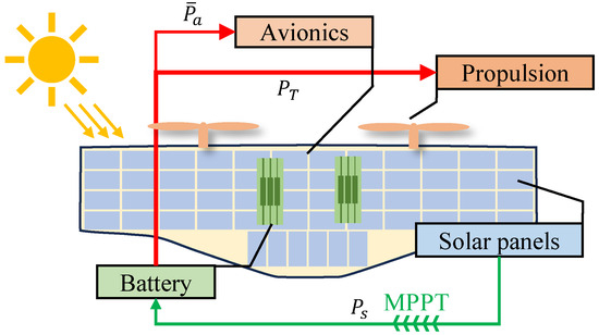
Figure 1.
The energy consumption and harvesting of a SMAV.
The power consumption is consistent with and . is used to balance the resistance during flight and can be obtained by experimentation. Details of the modeling of the propulsion system are provided in Appendix E. In this system, the battery functions analogously to a "reservoir": it discharges stored energy when solar power generation falls below consumption and stores surplus energy when generation exceeds demand. Battery testing and modeling methodologies are presented in the Appendix D. The generation of solar energy is modeled in the Appendix A, and is determined by the efficiency of the solar panels, , the number of panels deployed, , the current irradiance values, . It should be noted that the electric energy generated by solar panels cannot be directly used because the voltage is unstable. Therefore, maximum power point tracking (MPPT) hardware is required for adjustment, as shown in the Appendix B. To summarize, by modeling the solar energy, aerodynamics and power system characteristics, it is possible to assess the power consumption of the SMAV in flight.
2.2. Goal: Evaluation of Flight Duration
With the three parts of energy acquisition, consumption, and storage, we can quantitatively evaluate the endurance of a SMAV [41,42]. We focus on minimizing the net battery power consumption during level-flight cruising, as lower battery depletion enables longer endurance. Since different configurations exhibit distinct aerodynamic characteristics, we first address the trim condition for steady level flight, as depicted in Figure 2, the defined force and angles. Trim refers to the selection of appropriate control inputs to maintain altitude-stabilized horizontal flight. For the tailless SMAV in this paper, the control variables consist of: (1) The deflection angle of the thrust-vectoring mechanism. (2) The throttle setting . The longitudinal flight dynamics can be expressed as:
where H and X are the height and forward position in inertial axis. m is the mass while g is the gravitational acceleration. is the inertial along the y-direction of the SMAV. T is the thrust of the propulsion. They are multiplied by 2 because there are two rotors on both sides of the fuselage. is the force arm of thrust. The vectored thrust acts ahead of the center of gravity (COG). Thus, is the distance between the shaft of the vectored mechanism to COG. is the path angle. For longitudinal flight, is equal to the pitch angle minus the angle of attack (AOA). L, D, and M are the lift, drag, and moment of aerodynamics, respectively. The definition of those aerodynamics are:
where is the air density. , , are the coefficients of each. S is the wing area. is the mean chord length. The objective of trimming is to find the appropriate forward speed , , and , such that , , all equal zero. This optimization problem can be formulated as:
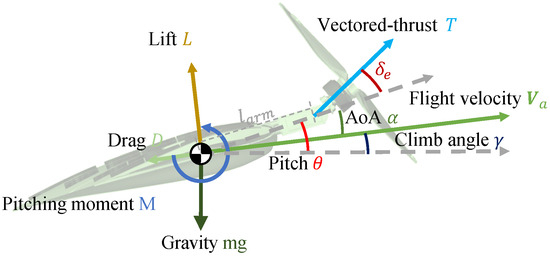
Figure 2.
Force and axis definition of SMAV.
The problem can be solved numerically. After obtaining the control inputs and states, we calculate the propulsion power consumption by substituting them into the relevant models. Using the photovoltaic estimation method from Section 3, we also determine the power generation, yielding the final optimization objective. The SMAV’s endurance is defined as:
where SOC stands for state of charge, which indicates the remaining charge level of a battery as a percentage of its full capacity. To maximize flight duration, we aim to minimize . Based on the energy system modeling, the optimization objectives are: (1) maximizing solar energy generation, (2) minimizing flight energy consumption, and (3) maximizing lift for slower flight speeds. While increasing MAC enlarges the wing area for greater solar power potential, it reduces aspect ratio and increases cruise energy consumption. This trade-off forms our optimization problem. The study employs a multi-objective non-dominated sorting genetic algorithm [43] (NSGA) for optimization, with parameters listed in Table 2 and the computational framework shown in Figure 3.
Table 2.
Parameter settings of NSGA-II.
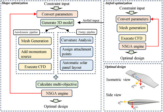
Figure 3.
Schematic of the optimization workflow. Balance the contradiction between aerodynamic efficiency and solar power generation performance through NSGA.
This section defines the SMAV’s energy system architecture and formulates the optimization objective through detailed modeling.
3. Shape Optimization Methodology
This section presents the aerodynamic optimization process. It covers the geometry control method, particularly how solar panel integration is incorporated into the automated optimization workflow. The construction of optimization objectives is also described.
3.1. Turbulence Model and Meshes
The SST turbulence model was selected for this study due to its ability to handle transitional and separated flows at low Reynolds numbers while maintaining numerical stability. This model employs equations near walls for accurate turbulent boundary layer resolution and switches to equations in the far field through a blending function. The computational domain extends more than 30 root chord lengths () from the fuselage center. No-slip wall conditions were applied to the MAV surfaces, with pressure outlets defining the far-field boundaries. A structured mesh approach was implemented, featuring boundary layers with and at least 10 layers for both propeller and fuselage. Curvature-sensitive regions received additional refinement to capture complex flow features. The independence of the mesh is verified. The element of the mesh for the airfoil is approximately . The slide mesh of the propeller uses about elements. When counting fuselage, it has nearly elements. The leading and trailing edges maintained a resolution with a growth rate. Through adaptive local refinement and multiple iteration cycles, the maximum skewness of the surface mesh was reduced to . Additionally, the worst cell quality in the volume mesh exceeded the threshold of . These improvements satisfy the convergence criteria for high-fidelity simulations. The CFD simulation setup and mesh details are presented in Figure 4.
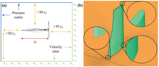
Figure 4.
CFD setups. (a) Computational domain and boundary condition setup. (b) Computational mesh.
In three-dimensional shape optimization, the fuselage is immersed in the propeller slipstream, requiring consideration of its aerodynamic effects. To balance accuracy and computational efficiency, the momentum source method is employed. This approach introduces source terms into the momentum equations to simulate propeller thrust and swirl effects while avoiding explicit geometry resolution.
3.2. MAV’s Geometry Control System
The aerodynamic optimization approach employs parametric geometry generation and evaluation [44,45,46]. Our design focuses on the MAV’s planar geometry for optimal solar panel integration, placing panels only on the upper fuselage surface. This single-sided configuration reduces weight and leverages the tilt-body design: during ground operation, the MAV naturally rests belly-down for optimal sun exposure. If accidentally inverted during landing, the vectored-thrust system can rotate to reorient the aircraft and realign the solar panels, eliminating the need for dual-side installation. The small surface area and high curvature of MAVs present solar panel deployment challenges. Our design maintains smooth curvature transitions on the upper surface to accommodate flexible photovoltaic cells while preventing installation damage. The blended wing-body (BWB) configuration maximizes available surface area for solar energy harvesting.
We implement a two-stage optimization process: first optimizing airfoils for high lift () and lift-to-drag ratio (E), then optimizing the wing outline. For airfoil generation, we use the Bezier-PARSEC method [47,48], dividing the thickness and camber functions into fore (third-order Bezier) and aft (fourth-order Bezier) sections at maximum height points. The wing design accommodates payload and folding requirements through four key regions (Figure 5): (1) forms the central fuselage for equipment housing, requiring specific thickness in profiles and ; (2) contains the folding hinge on the lower surface, with constrained curvature for hinge clearance; (3) represents the thinnest wingtip section within manufacturing limits; (4) serves as the transition between inner and outer wing segments.
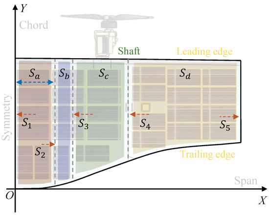
Figure 5.
Description of shape optimization.
Due to the thin profile of high-performance low-Reynolds airfoils, integrating avionics within the fuselage at MAV scale becomes impractical. We first developed a moderately thick airfoil (Figure 6), where C. and T. denote maximum camber and thickness, respectively, with the blue dashed line representing the middle arc. For symmetric fuselage sections, we maintained the optimized thin airfoil’s upper surface while redesigning the lower surface for electronic component accommodation (Figure 7). Spline control lines ensure smooth upper surface curvature, with minimum thickness requirements of 6% for outer sections (manufacturing constraints) and 17% for inner sections (payload requirements, see Appendix C). The A18 airfoil features 7.3% maximum thickness at 27.1% chord and 3.8% camber at 49.3% chord. Our outer section airfoil () shows 6.6% thickness at 19.7% chord and 4.8% camber at 36.7% chord, demonstrating reduced thickness, increased camber, and forward camber positioning for low-Reynolds conditions. The inner section airfoil () has 17.1% thickness at 26.4% chord and 1.0% camber at 75.0% chord.
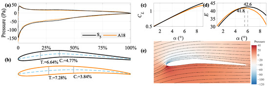
Figure 6.
Airfoil for outer section . (a) Pressure distribution along chord direction. (b) Airfoil shape comparison between A18 (an open source airfoil) and . (c) on different AOA. (d) Lift to drag ratio on different AOA. (e) Pressure contour plot and streamlines at .
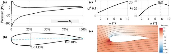
Figure 7.
Airfoil for inner section . (a) Pressure distribution along chord direction. (b) Airfoil shape . (c) on different AOA. (d) Lift to drag ratio on different AOA. (e) Pressure contour plot and streamlines at .
Using these optimized airfoils (Figure 6 and Figure 7), we developed a three-dimensional flying-wing configuration through leading edge distribution and chord length optimization. The design incorporates folding mechanisms by constraining edges to a common horizontal plane. Seventh-order Bezier curves define lateral offset and chord distribution (Figure 5), with curve parameters serving as optimization chromosomes and a fixed root chord of .
3.3. Adaptive Segmentation for Panel Deployment
A key contribution of this research is the integration of solar panel layout into the optimization process, enabling simultaneous energy–aerodynamic co-design. The automated solar panel layout problem constitutes a rectangle tiling problem on non-convex geometries, addressed through edge detection, curvature screening, non-convex hull trimming, region segmentation, and breadth-first search. For MAVs, their limited surface area and complex curvature distribution make conventional proportion-based solar panel deployment methods impractical [49,50]. Moreover, aerodynamically optimal shapes may not maximize solar energy capture—higher aspect ratios reduce wing area while improving aerodynamic efficiency. Our approach solves this through maximum coverage optimization for irregular polygons. The method considers practical constraints: (1) Solar panels have fixed dimensions (2 × 4 cm in this study) and electrical output depends on their area; (2) Panel flexibility limits installation on highly curved surfaces; (3) Only 90° rotations are allowed for wiring simplification; (4) No partial overlaps or external wing attachment due to fragility. The deployment process involves three steps: curvature analysis, attachment point assignment, and panel placement.
3.3.1. Curvature Analysis
The coordinates of the triangulated upper surface from the optimized arbitrary layout are extracted (Figure 8a).
where is the mean curvature and is the Gaussian curvature. The maximum principal curvature (the larger eigenvalue) is calculated by analyzing local surface regions (Figure 8b). To prevent solar panel damage from bending, regions near the leading edge are excluded from the layout (Figure 8c). Points exceeding curvature limits are filtered to define the adhesive-applicable area .
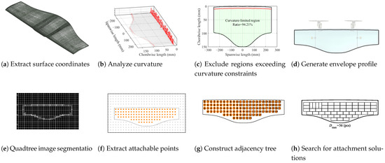
Figure 8.
Through the above steps, the optimized shape can be automatically attached with as many solar panels as possible so that the energy and aerodynamics can be included in the optimization process at the same time.
The minimum non-convex hull envelope of the remaining points is obtained using alpha shape methods. A parameter controls envelope tightness by removing Delaunay triangulation edges longer than , forming the final alpha shape (Figure 8d).
3.3.2. Assign Attachment Points
The next step is to devise an adhesive placement strategy within the interior of , which is enclosed by the sequence of points connected end to end. We can implement partitioning within the region using a quadtree image segmentation approach. However, before proceeding, we need to generate an image with a resolution that is a power of two for both axes and then establish a correspondence between physical scales and pixels. For example, consider a solar panel with dimensions as a rectangle. Let l be the greatest common divisor of and . Assuming that the length l occupies pixels, the wingspan of the MAV b corresponds to pixels. To maintain a higher level of precision, it is advisable to increase the value of n appropriately. Map the boundaries of onto an image containing pixels, where is the integer that is not less than it.
We employ a quadtree to progressively divide the image, as shown in Figure 8e. The maximum side length for each subdivision is set to pixels. The collection of all points with a side length of pixels is denoted as . The subdivision continues until it satisfies boundary recognition. Let represent the set of points where the boundary is located. The minimum non-convex hull that encompasses is denoted as , and the mapping of into the pixel space is denoted as . The condition is satisfied . Let , where . Then represents all sets of points that satisfy an interval of l. According to the generation criteria of the quadtree, consists of a series of square corner points with a side length of l, as shown in Figure 8f.
3.3.3. Panel Deployment
For square solar panels with side length l, denotes their attachment locations. When dealing with rectangular panels where , we combine points in . Given the typically small size of for MAVs, we employ a search-based approach to solve this combination problem. The random nature of searching allows multiple repetitions, enabling us to record the maximum attachment count . As we work with rectangular subdivisions, a quadtree structure can be established for adjacency, illustrated in Figure 8g. The pseudo-code for planning the deployment scheme is shown in the Algorithm 1.
| Algorithm 1: Panel deployment |
 |
The solar panels used in this study require pairing nodes in pairs, as illustrated in Figure 8h. The panel positions can be manually adjusted to accommodate cable routing and process requirements. This three-step approach enables automated deployment design for solar panels of various shapes, while the energy model allows analysis of solar energy production for any layout configuration.
4. Advantage Validation
The previous section addressed the mathematical formulation for automated solar panel attachment, successfully integrating energy considerations into the optimization framework. This section presents the optimization results, along with validation data from wind tunnel tests and flight experiments conducted on a prototype. We further analyze propeller-induced aerodynamic effects and finalize the stability configuration.
4.1. Optimization Results
The optimization framework shown in Figure 3 processes parameterized geometries through two parallel pipelines. The aerodynamic pipeline evaluates the lift-to-drag ratio (E) and lift coefficient () using RANS-based CFD simulations with automated structured mesh generation. The propeller’s momentum source terms are incorporated based on geometric positioning. Simultaneously, the energy pipeline follows the automated workflow in Section 3.3 to determine the maximum number of attachable solar panels (). By integrating these multi-objective results, the flight power consumption can be computed, yielding solutions that simultaneously optimize , E, and . The last iteration population is plotted in Figure 9, which also shows that some of the configurations are shown in shape. Those configurations exhibit comparable E ranging between 10 and 13. However, significant variations in the wing area result in substantially different solar panel attachment capacities (20–56 panels), creating notable disparities in endurance performance. Following the endurance evaluation methodology in Section 2, the configuration with maximum panel capacity is selected as the optimized design, as shown in Figure 10.
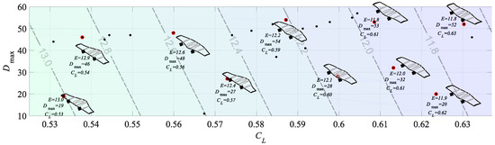
Figure 9.
Shape optimization results of SMAV.
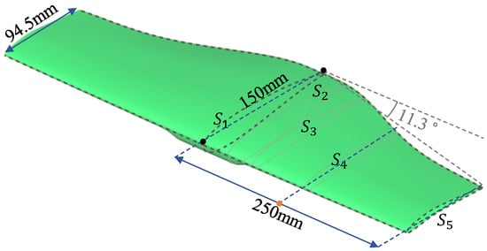
Figure 10.
The selected optimal configuration features a forward-swept flying-wing design with rapid chord reduction in the slipstream-affected region.
The selected configuration features forward-swept wings with nearly straight leading edges. These wings have a back sweep angle. It also includes curved trailing edges with an forward sweep angle. The chord length distribution gradually increases along the span. There are steeper reductions in propeller slipstream-dominated regions and gentler transitions in outer sections [51]. This solution demonstrates that the lift coefficient in is , E is , the taper ratio is , the aspect ratio is , the solar panel counts 56, the surface coverage ratio is approximately 74.7%.
4.2. Wind Tunnel Experiment
The test was carried out in a continuous return flow subsonic wind tunnel. The open test section has a diameter of and a length of . The model used was fabricated via additive manufacturing with stereolithography, featuring minimal shape errors and a density distinction. We could directly evaluate the mass and COG based on the design model. This allowed for self-weight correction using geometric relationships. All fastening connections are placed under the hatch to reduce gaps. After the hatch is closed, oil-based clay is used to seal the gaps and screw holes, with a scraper smoothing the surface to minimize interference. The test sensor is an ATI-Nano-17(IP68) [52]. This sensor is compact and ensures precision and an appropriate range for the experiment. Due to the small size of the cabin, the sensor is embedded inside the fuselage to reduce interference with the wind tunnel test. A belly support method is adopted to minimize damage to the upper surface and avoid affecting flow separation. A gap is reserved to prevent contact friction between the model and the sensor during testing. To reduce interference from incoming airflow entering the cavity, a raised hatch is designed to increase the depth of the cavity. The design drawings and test photos are shown in Figure 11.
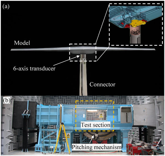
Figure 11.
Wind tunnel experiment setup with belly support. (a) Test model assembly structure and photo. (b) Photo of wind tunnel.
The blockage ratio, , is defined as Equation (9) and the result is 0.59%. Generally, wind tunnel tests require a blockage ratio below 5%, indicating that the stability and precision of the test flow field are well ensured. According to the flight conditions, the income flow velocity for this experiment is 9 m/s, resulting in a Reynolds number of approximately . The AOA varies from 0 to , while the sideslip angle is maintained at 0. Angle variation is achieved through an external sliding rail mechanism in the wind tunnel, as shown in Figure 11b. The model is precisely positioned at the intersection of the rotation axis and the centerline of the wind tunnel, eliminating additional interference from positional changes. The experimental results have been processed into dimensionless force coefficients and are shown in Figure 12. To avoid potential unsteady dynamics, we adjusted the AOA of the MAV very slowly. Furthermore, we measured the results of both increasing and decreasing sequences and averaged them at the same AOA.
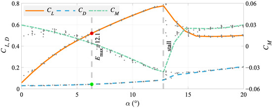
Figure 12.
Wind tunnel test results.
The experimental results demonstrate that the UAV has achieved the expected performance. The maximum lift-to-drag ratio is , which is achieved at an AOA of . The SMAV reaches its AOA in stall at approximately , whereupon the lift abruptly decreases by 30%, while the drag increases substantially. Beyond this point, the continued increase in AOA yields a gradual recovery in lift along with a persistent growth of drag. The COG of the SMAV is positioned at approximately the quarter-chord point, with the moment reference point coinciding with the COG. The moment variation characteristics demonstrate a negative slope () before the onset of the stall.
To visualize flow patterns more directly, we applied fluorescent-coated tufts on the upper wing surface, as shown in Figure 13. We prepare tufts by cutting lightweight wool threads to uniform lengths and saturating them in fluorescent oil suspension. After drying, these tufts are attached at equal intervals to the upper surface to visualize flow patterns. Under ultraviolet illumination, the movements of the tufts revealed flow separation characteristics across the upper surface. The results are compared with the CFD to visualize pressure and vorticity distributions across various AOA. The simulation and experiment both reveal the flow separation phenomenon. Through fluorescent tuft testing, we compared the upper surface vorticity distribution in calculations. The results showed that both experiments and computations exhibited separation regions of equivalent area at identical AOA, thereby demonstrating the comparability between simulations and experiments. Flow separation initiates at the trailing edge of the wing root section and progressively expands toward both the wingtips and the leading edge as the AOA increases, ultimately leading to complete stall.
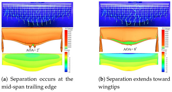
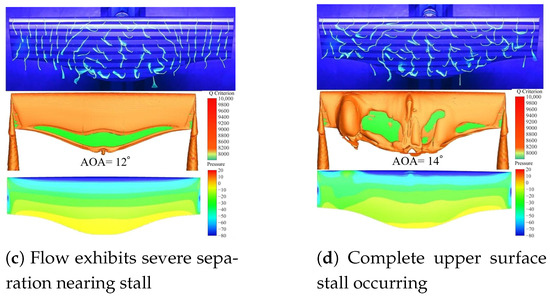
Figure 13.
Fluorescent tuft tests and comparison of the results with CFD.
Building on the trim analysis described in Section 2.2, the SMAV’s trim results are presented in Figure 14. Prior to the stall regime, the thrust requirement remains relatively low, corresponding to higher cruise efficiency during this phase. The SMAV should operate at relatively high AOA due to the fixed-pitch propeller’s reduced thrust efficiency at higher airspeeds. However, excessively high angles (particularly beyond the stall angle) induce substantial drag, compromising flight efficiency. So, it suggests an cruise AOA where the following are balanced: (1). Near-optimal aerodynamic performance. (2). Better flight stability, which is shown in Figure 15.
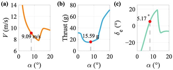
Figure 14.
Trim results. The black dot indicates the cruise status setting-points. (a) Trimmed flight speed. (b) Thrust needed in level flight. (c) Servo deflection angle.
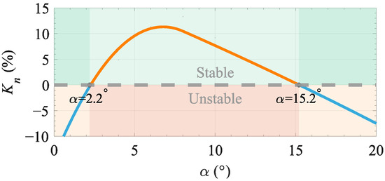
Figure 15.
Static margin for tailless flying wing from wind tunnel data. The green background color indicates stability within the AOA range, while red is unstable.
4.3. Flight in Reality
For this flying-wing MAV, the absence of an elevator necessitates additional stability verification prior to deployment, which ensures stable flight test conditions. The longitudinal static stability margin [53] is shown in Figure 15. This refers to the restoring moment that brings it back to its initial equilibrium state when disturbances occur. It depends mainly on the relative positions of the aerodynamic center and the COG . The method involves identifying a reference point for the pitching moment in the current AOA where . This point is defined as . The MAV’s remains fixed. The static margin is then calculated as the distance between these two points, normalized by .
where is the pitch moment reference point and x is positive from the leading edge to the trailing edge of the wing. When , is where is.
The static margin analysis confirms that the UAV maintains sufficient longitudinal stability throughout the cruise conditions. To comprehensively validate the effectiveness of the optimized design, a prototype MAV was manufactured. The monolithic carbon fiber part is formed via hot pressing. This technique ensures precise conformity to the mold geometry and strict adherence to the designed contours. The composition of the UAV broken down into components is shown in Figure 16. The main parameters are shown in Table 3. We designed the hardware and control algorithm of the flight controller based on an open-source framework named PX4. Prior to deployment for flight, we meticulously fine-tuned the controller’s parameters through flight dynamics simulation. Under clear skies and calm wind conditions, we collected data during a period of cruising flight, as shown in Figure 17.
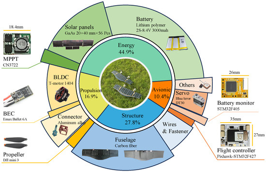
Figure 16.
Composition of mass by component.
Table 3.
Prototype of solar-powered MAV.
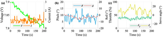
Figure 17.
A prototype is made. Power consumption is recorded in the cruise flight. (a) Battery voltage and current record during flight. (b) Pitching angle and rolling angle. (c) Control output.
During this 200 s cruise flight, the UAV maintained pitch angles between and . Subject to environmental disturbances (particularly wind effects), the MAV cannot achieve the precise attitude control characteristic of large commercial aircraft. The average cruise current measured . The flight data indicate an average power consumption of approximately during the cruise, in which there is about deduction from solar. Thus, the power consumption of propulsion is about . Furthermore, we utilize actual flight data to estimate endurance performance. We plotted the throttle of the SMAV during flight at different pitch angles on the same scatter plot and performed a fit, as shown in Figure 18. Take 30% of the battery capacity reserved for VTOL as an example. The results demonstrate a maximum potential flight duration of around 2.5 h. Thus, we have completed the entire design process that includes optimization, computation, verification, and flight testing. The results demonstrate a strong compatibility and feasibility for integrating solar technology with MAVs.
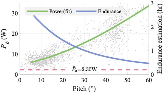
Figure 18.
Record the power consumption at different pitch angles and estimate the endurance.
5. Conclusions
Traditional MAVs typically lack extended endurance capabilities. Inspired by the successful application of clean energy in large-scale solar aircraft, the primary challenge lies in resolving the inherent conflict between aerodynamic efficiency and energy capture to maximize photovoltaic utilization. This study introduces a graphics-based segmentation and tree search algorithm that mathematically describes and automates solar cell placement for tailless flying-wing configurations. By employing parametric shape representation using Bezier curves, solar energy harvesting evaluation has been integrated into the MAV optimization process. Coupled with CFD, we successfully derived an endurance-optimized configuration. The result has been validated through wind tunnel testing. A prototype has been developed for flight testing. The data show approximately a 40% reduction in operational power consumption after photovoltaic integration. This leads to measurable improvements in endurance. In future work, we will conduct research on stable flight control to enable the SMAV to withstand disturbances in natural environments. This will aim to achieve more stable long-endurance flight.
Author Contributions
Conceptualization, W.D., Z.T. and D.L.; methodology, W.D., X.D. and H.L.; software, W.D., Z.W. and H.L.; validation, Z.W. and Z.T.; investigation, W.D. and X.D.; writing—original draft preparation, W.D.; writing—review and editing, Z.T.; supervision, J.X. and D.L.; project administration, Z.T. All authors have read and agreed to the published version of the manuscript.
Funding
Supported by the Fundamental Research Funds for the Central Universities.
Data Availability Statement
The data presented in this study are available on request from the corresponding author.
Conflicts of Interest
Haoji Liu is employed by AVIC Chengdu Aircraft Industrial (Group) Company Limited. The remaining author declares that the research was conducted in the absence of any commercial or financial relationships that could be construed as a potential conflict of interest.
Appendix A. Photovoltaic Energy Harvesting

Figure A1.
Ground-based solar energy test. (a) Voltage and current change. (b) Solar irradiance and charged capacity. (c) Efficiency of MPPT and solar panels. (d) Photos of test conditions.
The solar aircraft achieves energy replenishment in flight by converting solar energy into electrical energy. The irradiance is modeled by the geometric relationship between the Earth and the Sun. To evaluate the energy changes in SMAV over a certain period of time, we need to establish a harvesting model that is related to position, attitude, and time [54,55].
The output power of the solar panels, can be expressed as:
where, is the energy conversion efficiency of the solar panels, is the MPPT efficiency, and is the area where the solar panels are laid. We conducted ground tests on the entire energy system of the aircraft. During the transition between summer and autumn, we initiated charging at 2:00 p.m. and continued until the onboard battery was mostly charged. We recorded various parameters of the energy system and plotted them in Figure A1.
Appendix B. Tiny MPPT Design for SMAV
MPPT is a technique used in solar charge controllers and other power systems to maximize the energy harvested from photovoltaic panels [56]. The MPPT algorithm continuously adjusts the electrical operating point of the PV panels to ensure efficiency under varying sunlight intensity and temperature. We have released the circuit diagram, visible in Figure A2a. It is a centimeter sized miniature circuit that can be integrated into the MAV fuselage, as shown in Figure A2b.

Figure A2.
An integrated MPPT with high efficiency. (a) Schematic: the CN3722 adopts constant voltage method for voltage modulation. (b) Dimensions of microcircuits. (c) Energy from solar-to-battery conversion test by MPPT. (d) Efficiency of MPPT on various voltages and currents.
Although the energy level of MAV is relatively small, efficiency is still an important factor affecting heat dissipation and performance. We tested the MPPT conversion efficiency, at different input powers, and output voltages, . The results are shown in Figure A2c,d. It can be seen that, during most of the daytime, is greater than , and the conversion performance only significantly decreases when the lighting weakens in the evening. By fitting in polynomial form, we can quickly obtain based on solar input and battery output, thereby establishing an electrical parameter model for MPPT.
Appendix C. Avionics Installation Space Analysis
The mid-section employs a thick airfoil to ensure internal payload space. An interesting question is how to determine the maximum size of a cuboid (e.g., a battery) that can fit within this non-convex curved enclosure. Assume the battery is symmetrically placed in the mid-fuselage with a 40 mm gap reserved for flight controllers and circuits, and given that the optimized fuselage contour defines the outer surface with a shell thickness. This thickness accounts for the structural foam and carbon fiber layup. The problem can be formulated as follows: Let the eight vertices of the battery be labeled ~, with ~ positioned 20 mm from the symmetry plane. By adjusting the coordinates of these vertices (e.g., vertex ), the constraint must be satisfied, where represents any point on the fuselage surface. This condition applies to all eight vertices. Thus, a multi-parameter optimization problem is established, maximizing volume under these constraints. The optimization results are illustrated in Figure A3.

Figure A3.
Analysis on internal space for avionics. Extract the largest box in the shape envelope (gray mesh grid). The portion below the plane (translucent green) has compressed coordinates, as this space is sufficiently large.
Appendix D. Rechargeable Battery
The SMAV is equipped with a rechargeable battery. Its remaining charge can be described by SOC. The lower the remaining charge, the smaller the open-circuit voltage (OCV) of the battery; this relationship is shown in Figure A4a. A simple rechargeable lithium battery can be modeled by a second-order RC circuit, as shown in Figure A4b, where the resistance can be measured through experiments [57]. By applying a step current output, observe the voltage drop from point a to point b in Figure A4b, then calculate the resistance. After maintaining this state for a period, the voltage drops to point c. Upon stopping the discharge at point d, observe the gradual voltage recovery process. The voltage data after point d is used to fit the characteristics of the battery.

Figure A4.
Rechargeable battery modeled and test. (a) Relationship between SOC and OCV. (b) Battery voltage curve under step current load. (c) A complete discharge process. (d) The battery SOC model has higher accuracy.
Appendix E. Electric Propulsion
We employed Kalman filtering to estimate the SOC by analyzing the current and voltage data consumed during battery capacity in real time. A complete test is shown in Figure A4c,d. Among them, Figure A4c records the voltage and current during the discharge process, and Figure A4d compares the changes in SOC. PX4 is an open-source flight control program that also provides an estimation model based on internal resistance and voltage drop. In contrast, the model established in this paper is more stable and accurate in estimating electricity consumption. The servo and rotor form a vectoring unit through a connection mechanism, allowing a maximum deflection of ±90°. Therefore, when the aircraft needs any maneuver, the propeller can rotate and generate effective torque while avoiding forces or moments of other degrees of freedom. The single-sided propeller can provide a maximum pulling force of 150 g (shown in Figure A5a), and the first order time constant of the rotor is 78 ms, which can provide a sensitive and sufficient pulling force.

Figure A5.
Vectored-thrust propulsion test. (a) Thrust due to different throttle and income airflow speed. The dots represent experimental data, while the surface represents the fitted results. (b) Wind tunnel experiment photo.
refers to the velocity of the income flow. Unlike tailsitters, this MAV adopts a belly-landing approach. It can hover with a vertical fuselage orientation. However, upon landing, it does not stand upright but naturally lies flat under gravity. This allows the solar panels on the fuselage surface to remain horizontal to convert solar energy. When takeoff is required, the propulsion system tilts to a vertical direction, lifting the fuselage.
References
- Elbanhawi, M.; Mohamed, A.; Clothier, R.; Palmer, J.; Simic, M.; Watkins, S. Enabling technologies for autonomous MAV operations. Prog. Aerosp. Sci. 2017, 91, 27–52. [Google Scholar] [CrossRef]
- Mohsan, S.A.H.; Othman, N.Q.H.; Khan, M.A.; Amjad, H.; Żywiołek, J. A Comprehensive Review of Micro UAV Charging Techniques. Micromachines 2022, 13, 977. [Google Scholar] [CrossRef] [PubMed]
- Airbus. Zephyr HAPS. 2025. Available online: https://www.airbus.com/en/products-services/defence/uas/zephyr (accessed on 6 July 2025).
- Lei, T.; Min, Z.; Gao, Q.; Song, L.; Zhang, X.; Zhang, X. The Architecture Optimization and Energy Management Technology of Aircraft Power Systems: A Review and Future Trends. Energies 2022, 15, 4109. [Google Scholar] [CrossRef]
- Brelje, B. Multidisciplinary Design Optimization of Electric Aircraft Considering Systems Modeling and Packaging. Ph.D. Thesis, University of Michigan, Ann Arbor, MI, USA, 2021. [Google Scholar]
- El-Salamony, M.E.; Aziz, M.A. Impact of N-Shaped Wing Morphing on Solar-Powered Aircraft. Unmanned Syst. 2020, 09, 309–320. [Google Scholar] [CrossRef]
- Siyu, L.; Kangwen, S.; Jian, G.; Haoquan, L. Receiving energy analysis and optimal design of crystalline silicon solar cell array on solar airship. Energy 2023, 282, 128988. [Google Scholar] [CrossRef]
- Wu, M.; Shi, Z.; Xiao, T.; Ang, H. Effect of wingtip connection on the energy and flight endurance performance of solar aircraft. Aerosp. Sci. Technol. 2021, 108, 106404. [Google Scholar] [CrossRef]
- El-Atab, N.; Mishra, R.B.; Alshanbari, R.; Hussain, M.M. Solar Powered Small Unmanned Aerial Vehicles: A Review. Energy Technol. 2021, 9, 2100587. [Google Scholar] [CrossRef]
- Sornek, K.; Augustyn-Nadzieja, J.; Rosikoń, I.; Łopusiewicz, R.; Łopusiewicz, M. Status and Development Prospects of Solar-Powered Unmanned Aerial Vehicles—A Literature Review. Energies 2025, 18, 1924. [Google Scholar] [CrossRef]
- Noth, A. Design of Solar Powered Airplanes for Continous Flight. Ph.D. Thesis, ETH Zurich, Zurich, Switzerland, 2008. [Google Scholar]
- Li, X.; Sun, K.; Li, F. General optimal design of solar-powered unmanned aerial vehicle for priority considering propulsion system. Chin. J. Aeronaut. 2020, 33, 2176–2188. [Google Scholar] [CrossRef]
- Yao, Z. Aerodynamic, Structures and Energy Coupled Multi-Objecitve Optimization for Solar Powered UAV’s Wing. Master’s Thesis, Beijing Institute of Technology, Beijing, China, 2015. [Google Scholar]
- Peciak, M.; Skarka, W.; Mateja, K.; Gude, M. Impact Analysis of Solar Cells on Vertical Take-Off and Landing (VTOL) Fixed-Wing UAV. Aerospace 2023, 10, 247. [Google Scholar] [CrossRef]
- Carlson, S.J.; Papachristos, C. Solar Energy Harvesting for a Land-to-Recharge Tiltrotor Micro Aerial Vehicle. In Proceedings of the 2022 IEEE Aerospace Conference (AERO), Big Sky, MT, USA, 5–12 March 2022; pp. 1–8. [Google Scholar] [CrossRef]
- Leutenegger, S.; Jabas, M.; Siegwart, R.Y. Solar Airplane Conceptual Design and Performance Estimation: What Size to Choose and What Endurance to Expect. J. Intell. Robot. Syst. 2010, 61, 545–561. [Google Scholar] [CrossRef]
- Turk, I.; Ozbek, E.; Ekici, S.; Karakoc, T.H. A conceptual design of a solar powered UAV and assessment for continental climate flight conditions. Int. J. Green Energy 2021, 19, 638–648. [Google Scholar] [CrossRef]
- Grasmeyer, J.; Keennon, M. Development of the Black Widow Micro Air Vehicle. In Proceedings of the 39th Aerospace Sciences Meeting and Exhibit, Reno, NV, USA, 8–11 January 2001; American Institute of Aeronautics and Astronautics: Reston, VA, USA, 2001. [Google Scholar] [CrossRef]
- Roberts, C.; Vaughan, M.; Bowman, W. Development of a solar powered micro air vehicle. In Proceedings of the 40th AIAA Aerospace Sciences Meeting & Exhibit, Reno, NV, USA, 14–17 January 2002; American Institute of Aeronautics and Astronautics: Reston, VA, USA, 2002. [Google Scholar] [CrossRef][Green Version]
- Kellogg, J.; Bovais, C.; Foch, R.; McFarlane, H.; Sullivan, C.; Dahlburg, J.; Gardner, J.; Ramamurti, R.; Gordon-Spears, D.; Hartley, R.; et al. The NRL micro tactical expendable (MITE) air vehicle. Aeronaut. J. 2002, 106, 431–442. [Google Scholar] [CrossRef]
- Wu, H.; Sun, D.; Zhou, Z. Micro Air Vehicle: Configuration, Analysis, Fabrication, and Test. IEEE/ASME Trans. Mechatron. 2004, 9, 108–117. [Google Scholar] [CrossRef]
- Shyy, W.; Berg, M.; Ljungqvist, D. Flapping and flexible wings for biological and micro air vehicles. Prog. Aerosp. Sci. 1999, 35, 455–505. [Google Scholar] [CrossRef]
- Thipyopas, C.; Moschetta, J.M. A Fixed-Wing Biplane MAV for Low Speed Missions. Int. J. Micro Air Veh. 2009, 1, 13–33. [Google Scholar] [CrossRef]
- Keennon, M.; Klingebiel, K.; Won, H. Development of the Nano Hummingbird: A Tailless Flapping Wing Micro Air Vehicle. In Proceedings of the 50th AIAA Aerospace Sciences Meeting including the New Horizons Forum and Aerospace Exposition, Nashville, TN, USA, 9–12 January 2012; American Institute of Aeronautics and Astronautics: Reston, VA, USA, 2012. [Google Scholar] [CrossRef]
- Leutenegger, S. Unmanned Solar Airplanes: Design and Algorithms for Efficient and Robust Autonomous Operation. Ph.D. Thesis, ETH Zurich, Zurich, Switzerland, 2014. [Google Scholar]
- Radmanesh, M.; Nematollahi, O.; Nili-Ahmadabadi, M.; Hassanalian, M. A novel strategy for designing and manufacturing a fixed wing MAV for the purpose of increasing maneuverability and stability in longitudinal axis. J. Appl. Fluid Mech. 2014, 7, 435–446. [Google Scholar] [CrossRef]
- ETH Zurich. Atlantiksolar. 2025. Available online: https://www.atlantiksolar.ethz.ch/ (accessed on 6 July 2025).
- Shaheed, M.H.; Abidali, A.; Ahmed, J.; Ahmed, S.; Burba, I.; Fani, P.J.; Kwofie, G.; Wojewoda, K.; Munjiza, A. Flying by the Sun only: The Solarcopter prototype. Aerosp. Sci. Technol. 2015, 45, 209–214. [Google Scholar] [CrossRef]
- Perez-Rosado, A.; Gehlhar, R.D.; Nolen, S.; Gupta, S.K.; Bruck, H.A. Design, fabrication, and characterization of multifunctional wings to harvest solar energy in flapping wing air vehicles. Smart Mater. Struct. 2015, 24, 065042. [Google Scholar] [CrossRef]
- D’Sa, R.; Jenson, D.; Papanikolopoulos, N. SUAV:Q—A hybrid approach to solar-powered flight. In Proceedings of the 2016 IEEE International Conference on Robotics and Automation (ICRA), Stockholm, Sweden, 16–21 May 2016; pp. 3288–3294. [Google Scholar] [CrossRef]
- Hassanalian, M.; Abdelkefi, A. Design, manufacturing, and flight testing of a fixed wing micro air vehicle with Zimmerman planform. Meccanica 2016, 52, 1265–1282. [Google Scholar] [CrossRef]
- Wu, Y.; Du, X.; Duivenvoorden, R.; Kelly, J. The Phoenix Drone: An Open-Source Dual-Rotor Tail-Sitter Platform for Research and Education. In Proceedings of the IEEE 2019 International Conference on Robotics and Automation (ICRA), Montreal, QC, Canada, 20–24 May 2019. [Google Scholar] [CrossRef][Green Version]
- Tetreault, E.; Rancourt, D.; Lussier Desbiens, A. Active Vertical Takeoff of an Aquatic UAV. IEEE Robot. Autom. Lett. 2020, 5, 4844–4851. [Google Scholar] [CrossRef]
- Aboelezz, A.; Hassanalian, M.; Desoki, A.; Elhadidi, B.; El-Bayoumi, G. Design, experimental investigation, and nonlinear flight dynamics with atmospheric disturbances of a fixed-wing micro air vehicle. Aerosp. Sci. Technol. 2020, 97, 105636. [Google Scholar] [CrossRef]
- Ionescu, O.N.; Cernica, I.; Manea, E.; Parvulescu, C.; Istrate, A.; Ionescu, G.; Suchea, M.P. Integration of Micro-Structured Photovoltaic Cells into the Ultra-Light Wing Structure for Extended Range Unmanned Aerial Vehicles. Appl. Sci. 2021, 11, 10890. [Google Scholar] [CrossRef]
- Elkunchwar, N.; Chandrasekaran, S.; Iyer, V.; Fuller, S.B. Toward battery-free flight: Duty cycled recharging of small drones. In Proceedings of the 2021 IEEE/RSJ International Conference on Intelligent Robots and Systems (IROS), Prague, Czech Republic, 27 September–1 October 2021; pp. 5234–5241. [Google Scholar] [CrossRef]
- Wang, K.; Zhou, Z. An investigation on the aerodynamic performance of a hand-launched solar-powered UAV in flying wing configuration. Aerosp. Sci. Technol. 2022, 129, 107804. [Google Scholar] [CrossRef]
- Oliva, J. Design and Fabrication of a Solar Powered MAV. Ph.D. Thesis, Toronto Metropolitan University, Toronto, ON, USA, 2024. [Google Scholar] [CrossRef]
- Abidali, A.; Agha, S.A.; Munjiza, A.; Shaheed, M.H. Development of a solar powered multirotor micro aerial vehicle. Sci. Rep. 2024, 14, 5771. [Google Scholar] [CrossRef]
- Cao, X.; Liu, L. State-of-Charge Trajectory Planning for Low-Altitude Solar-Powered Convertible UAV by Driven Modes. Drones 2024, 8, 80. [Google Scholar] [CrossRef]
- Liller, J.; Goel, R.; Aziz, A.; Hester, J.; Nguyen, P. Development of a battery free, solar powered, and energy aware fixed wing unmanned aerial vehicle. Sci. Rep. 2025, 15, 6141. [Google Scholar] [CrossRef]
- Chu, Y.; Ho, C.; Lee, Y.; Li, B. Development of a Solar-Powered Unmanned Aerial Vehicle for Extended Flight Endurance. Drones 2021, 5, 44. [Google Scholar] [CrossRef]
- Deb, K.; Pratap, A.; Agarwal, S.; Meyarivan, T. A fast and elitist multiobjective genetic algorithm: NSGA-II. IEEE Trans. Evol. Comput. 2002, 6, 182–197. [Google Scholar] [CrossRef]
- Cipolla, V.; Dine, A.; Viti, A.; Binante, V. MDAO and Aeroelastic Analyses of Small Solar-Powered UAVs with Box-Wing and Tandem-Wing Architectures. Aerospace 2023, 10, 105. [Google Scholar] [CrossRef]
- Bakar, A.; Ke, L.; Liu, H.; Xu, Z.; Wen, D. Design of Low Altitude Long Endurance Solar-Powered UAV Using Genetic Algorithm. Aerospace 2021, 8, 228. [Google Scholar] [CrossRef]
- Manikandan, M.; Pant, R.S. Design optimization of a tri-lobed solar powered stratospheric airship. Aerosp. Sci. Technol. 2019, 91, 255–262. [Google Scholar] [CrossRef]
- Salunke, N.P.; Ahamad, R.A.J.; Channiwala, S. Airfoil Parameterization Techniques: A Review. Am. J. Mech. Eng. 2014, 2, 99–102. [Google Scholar] [CrossRef]
- Liu, H.; Di, W.; Wei, Z.; Li, D.; Xiang, J.; Tu, Z. Aerodynamic optimization design of low reynolds number aerofoils based on induced laminar separation. J. Phys. Conf. Ser. 2024, 2764, 012019. [Google Scholar] [CrossRef]
- García-Gascón, C.; Castelló-Pedrero, P.; García-Manrique, J.A. Minimal Surfaces as an Innovative Solution for the Design of an Additive Manufactured Solar-Powered Unmanned Aerial Vehicle (UAV). Drones 2022, 6, 285. [Google Scholar] [CrossRef]
- Liu, Y.; Du, H.; Xu, Z.; Sun, K.; Lv, M. Mission-based optimization of insulation layer for the solar array on the stratospheric airship. Renew. Energy 2022, 191, 318–329. [Google Scholar] [CrossRef]
- Rakshith, B.R.; Deshpande, S.M.; Narasimha, R.; Praveen, C. Optimal Low-Drag Wing Planforms for Tractor-Configuration Propeller-Driven Aircraft. J. Aircr. 2015, 52, 1791–1801. [Google Scholar] [CrossRef]
- Automation, A.I. F/T Sensor, Nano17 IP65/IP68. 2025. Available online: https://www.ati-ia.com/products/ft/ft_models.aspx?id=Nano17+IP65%2fIP68 (accessed on 6 July 2025).
- Pamadi, B.N. Performance, Stability, Dynamics, and Control of Airplanes, 2nd ed.; American Institute of Aeronautics and Astronautics: Reston, VA, USA, 2004. [Google Scholar] [CrossRef]
- Pande, D.; Verstraete, D. Impact of solar cell characteristics and operating conditions on the sizing of a solar powered nonrigid airship. Aerosp. Sci. Technol. 2018, 72, 353–363. [Google Scholar] [CrossRef]
- Zhu, W.; Xu, Y.; Li, J.; Zhang, L. Performance analysis of rotatable energy system of high-altitude airships in real wind field. Aerosp. Sci. Technol. 2020, 98, 105689. [Google Scholar] [CrossRef]
- Carlson, S.J.; Karakurt, T.; Arora, P.; Papachristos, C. Integrated Solar Power Harvesting and Hibernation for a Recurrent-Mission VTOL Micro Aerial Vehicle. In Proceedings of the IEEE 2022 International Conference on Unmanned Aircraft Systems (ICUAS), Dubrovnik, Croatia, 21–24 June 2022; pp. 237–244. [Google Scholar] [CrossRef]
- Zhang, C.; Zhang, C.; Li, L.; Guo, Q. Parameter analysis of power system for solar-powered unmanned aerial vehicle. Appl. Energy 2021, 295, 117031. [Google Scholar] [CrossRef]
Disclaimer/Publisher’s Note: The statements, opinions and data contained in all publications are solely those of the individual author(s) and contributor(s) and not of MDPI and/or the editor(s). MDPI and/or the editor(s) disclaim responsibility for any injury to people or property resulting from any ideas, methods, instructions or products referred to in the content. |
© 2025 by the authors. Licensee MDPI, Basel, Switzerland. This article is an open access article distributed under the terms and conditions of the Creative Commons Attribution (CC BY) license (https://creativecommons.org/licenses/by/4.0/).