Highlights
What are the main findings?
- An expanded space observer is designed to perform two observations, creating safe regions as UAVs approach obstacles of any shape from arbitrary orientations. Local target points are then generated within these regions to guide UAV flight paths.
- An improved Soft Differential Constrained Minimum Snap algorithm is developed, transforming endpoint differential terms (velocity, acceleration) from hard constraints into cooperatively optimized parameters with path coefficients.
What are the implications of the main findings?
- Through the directional guidance of local target points, combined with path memory points and backtracking algorithm, a general UAV path planning framework is proposed for high-density and large-sized obstacle scenarios.
- Soft constraints and self-regulation of path endpoint differential terms enhance their coupling with the parameters of the polynomial path equation, ultimately generating optimized trajectories that enable faster UAVs transit.
Abstract
Autonomous navigation of unmanned aerial vehicles (UAVs) in unknown complex environments requires safe, fast and efficient path planning algorithms. Currently, the two-stage framework of “front-end search and back-end optimization” is widely adopted. However, existing research primarily focuses on path planning performance in high-density obstacle scenarios, lacking effective strategies for large-sized obstacles. Furthermore, the current two-stage framework suffers from issues such as path divergence and reduced flight speed. To address these limitations, this paper proposes a general path planning algorithm with soft constraints for UAVs in high-density obstacle scenarios and large-sized obstacle scenarios. The core of the algorithm involves guiding the UAV trajectory through the establishment of well-defined local target points. The front-end employs an expanded space observer for two observations, constructing a real-time safety region, and integrates flight state information to generate local target points using reinforcement learning. The back-end generates trajectories that allows UAVs to fly towards the local target points at higher speeds through an improved Soft Differential Constrained Minimum Snap (SDC-Minimum Snap) algorithm. For large-sized obstacles, a cost-function-based backtracking and circumvention mechanism is introduced to ensure reliable obstacle avoidance. Simulations and real-world experiments validate the generality and feasibility of the proposed algorithm in both scenarios.
1. Introduction
In recent years, UAVs have played an important role in applications such as forestry resource surveys, high-voltage circuit inspections and logistics airspace distribution due to their flexible passage and diverse loads. For environments without prior maps, real-time path planning algorithms for a UAV are crucial for mission success.
Currently, the two-stage framework of “front-end search and back-end optimization” has been widely used. Its key advantage lies in the decoupling of search and optimization, which enables algorithms to have greater flexibility in optimization space and faster multi constraint solution [1,2]. In the front end, a path search generates obstacle-avoidance trajectories that satisfy feasibility requirements. In the back-end, the initial path is refined through smoothness optimization and dynamic optimization based on continuity and differentiability constraints, ultimately producing executable flight paths for UAVs.
Improving flight speed is one of the optimization directions for UAV path planning algorithms. Building upon the traditional Rapid Random Search Tree (RRT), Ref. [3] proposes an adaptive stride RRT path search algorithm. By maximizing information-sensing efficiency in unstructured environments, this approach improves decision accuracy, thereby increasing UAV flight velocity. Ref. [4] also enhances RRT by predicting high-speed passageways to direct path sampling, advancing beyond step-size tuning to satisfy high-speed flight requirements. However, the aforementioned RRT-based algorithms suffer from search redundancy. Addressing this, Ref. [5] replaces RRT redundant path search with a risk perception function to enable UAVs to travel at a faster speed in low-risk areas. This method places high demands on the perception module. To reduce the interference of perception noise, Ref. [6] uses a highly maneuverable backup route to increase robustness and maintain high-speed traffic while meeting the safety constraints of local obstacles. As this method essentially constitutes a specific environment-state-based optimization solver, its generalization capability across diverse obstacle environments requires further improvement. Speed optimization based on dynamic models can enhance environmental adaptability [7,8]. Within this framework, one specific approach involves optimizing the solution to dynamic constraint equations using a fuzzy penalty function [9], while another method involves sampling and connecting kinematically feasible paths within the state space [10]. Nevertheless, dynamic model-based path planning demands high precision in UAV modeling, and requires comprehensive consideration of complex system models such as fluid mechanics and electromechanics. Considering the high requirements for real-world experiments, Ref. [11] proposes a digital twin framework for UAV swarms. By bridging the virtual and real worlds, this framework streamlines the validation of UAV algorithms, such as those designed to increase flight speed.
Path efficiency is another important indicator for measuring UAV path planning algorithms. A classical approach involves secondary correction of heuristic-based paths, such as A* optimization algorithm based on heuristic evaluation function [12], B-spline optimization based on sliding window [13], and proximity function optimization based on Nussbaum [14]. However, such secondary correction methods heavily depend on initial path quality and essentially constitute non-globally optimal local optimization. To address this limitation, paper [15] achieves initial path optimization by introducing the minimum volume enclosing polynomial curves (MINVO) basis function, thereby resolving the hull conservation issue and enhancing path efficiency. However, it should be noted that relying solely on onboard sensors can only detect the surface of obstacles, making it impossible to obtain information about what lies behind the obstacle surface in real time. Although some bio-inspired search algorithms have good decision-making and path convergence abilities in environments with prior maps [16,17,18], their path efficiency is suppressed in unknown environments. Ref. [19] categorizes these issues as perception inadequacies. According to this, Ref. [20] proposes a perception awareness (PA) fast detection algorithm based on incremental convex perception shells, which reduces redundant paths by combining motion element propagation algorithms. Another approach transforms the insufficient perception problem into a Maximum A Posteriori (MAP) problem, utilizing Gaussian Processes (GP) to design distribution functions and solving the probability problem to achieve more efficient paths [21]. However, for scenarios that require continuous obstacle avoidance, it is still difficult to ensure path convergence, resulting in path divergence and reduced path efficiency.
In addition, large-sized obstacle scenarios pose new challenges to path planning. Unlike high-density obstacle scenarios, environments featuring large obstacles (e.g., long straight obstacles or L-shaped obstacles) make it difficult for UAVs to find a feasible path, leading to issues such as back-and-forth wandering, getting stuck in local optima, or outright failure. Although swarm-based approaches can extend perception range and optimize obstacle avoidance for large-sized obstacles [22,23,24], the challenge remains significant for individual UAVs. Ref. [25] proposed a hybrid surface model to direct the growth of the RRT algorithm along obstacle contours, but it is prone to getting stuck in local optima. To address local optima, Ref. [26] proposes a gravitational field scheme inspired by thermodynamic flow models, using a gradually accumulating repulsive force generated at local corners to push UAVs away from local optimal environments. A similar approach in [27] employs state and action entropy to incentivize path planning. However, the avoidance direction of these approaches is uncertain and does not indicate the correct path planning direction. To address this, a sampling algorithm based on evaluation functions can generate feasible trajectories by combining discrete search paths [28,29], but this increases redundant flight paths. Ref. [30] employs fast Euclidean clustering method to obtain the obstacle center points, and generates RRT diffusion path based on these points. Although this method can generate efficient detour paths, it is difficult to obtain the obstacle’s center points.
This paper proposes a general UAV path planning algorithm for high-density and large-sized obstacle scenarios, and improves path efficiency and flight speed. At the front end, an expanded space observer is introduced to discern obstacle dimensions through two observations and generate a safe region. Within the safe region, local target points are generated using a Twin Delayed Deep Deterministic Policy Gradient (TD3). For large-sized obstacles, path memory points are created alongside the local target points, which will then be utilized by a backtracking algorithm. At the back end, an improved Soft Differential Constrained Minimum Snap (SDC-Minimum Snap) algorithm is proposed. This method transforms the trajectory endpoint differential terms (velocity, acceleration) from hard constraints into a set of parameters that are cooperatively optimized alongside the path coefficients. This enhances the coupling between UAV flight speed, acceleration, and the planned trajectory. For small-sized obstacles, this algorithm directly generates paths to the local target points through SDC-Minimum Snap and iteratively avoids obstacles. For large obstacles, a cost comparison is introduced between the local target point and the path memory points before path optimization. By employing a dynamically self-adjusting parameter for cost balance alongside a backtracking algorithm, the system effectively resolves issues of wandering and local optima entrapment. The generality of the proposed method lies in its unified algorithm for generating local target points, which is applicable to both high-density and large-sized obstacle scenarios and ensures effective UAV guidance. Figure 1 shows the overall system framework.

Figure 1.
Overall system framework.
This paper comprehensively considers high-density-obstacle scenarios and large-sized-obstacle scenarios, and proposes a general algorithm framework to guide path planning based on local target points. The main contributions of this paper are:
(1) By actively generating local target points to guide UAV flight, a general path planning framework is established for both high-density and large-sized obstacle scenarios. For large-sized obstacles, the system incorporates path memory points and a dynamically adjusted cost function to determine the UAV’s guidance direction. This approach addresses the problem of oscillatory behaviors and local optimum traps commonly encountered with large obstacles. Simulation and real-world experiments validate the generalized path planning capability of proposed method in both high-density and large-sized obstacle scenarios.
(2) An expanded space observer is proposed to perform two observations for determining the dimensions of obstacles with arbitrary shapes from any approach angle. Subsequently, a safe region is generated from the observations, and local target points are generated within it through deep reinforcement learning. This reduces path divergence during continuous obstacle avoidance, generating more efficient paths.
(3) The proposed SDC-Minimum Snap algorithm treats the path-end differential terms not as hard constraints but as parameters for cooperative optimization with polynomial path parameters. By adaptively adjusting the path parameters, the coupling between the UAV flight speed and the path is increased, ultimately generating paths enabling faster UAV passage.
The overall structure of this paper is as follows: Section 2 introduces and analyzes the method proposed in this paper. Section 2.1 is the local target searching algorithm, including the extended space observer and the local target point generation algorithm. Section 2.2 is about path optimization algorithm, including SDC-Minimum Snap and path memory point backtracking algorithm. Section 3 validates the algorithm in this paper through simulation and real-world experiments. Section 4 discusses the algorithm and experimental results of this paper. The fifth section provides a summary of the entire paper.
2. Methods
The methods in this paper include the local target searching algorithm in Section 2.1 and the path optimization algorithm in Section 2.2. In the first algorithm, the initial step involves generating a safe region through two observations of obstacles using an expanded space observer. Secondly, a local target point is generated within the safe region to guide the UAV flight direction. Following this, the path to the local target point is optimized using the framework outlined in Section 2.2, through the SDC-Minimum Snap, and the path memory point backtracking algorithm when facing large-sized obstacles.
2.1. Local Target Searching Algorithm
The local target searching algorithm proposed in this study comprises two components: the expanded space observer and the local target point generation algorithm. The role of the expanded space observer is to initially generate a safe region when UAVs encounter obstacles. Subsequently, using TD3 algorithm generates local target points within this safe region. When encountering large obstacles, path memory points are additionally generated. Here, the local target point represents the immediate objective for the UAV’s current movement, while path memory points are utilized for the backtracking algorithm described in Section 2.2.2.
2.1.1. Expanded Space Observer
The Expanded Space Observer generates a safe region based on the environment perceived by sensors. First, the concept of a forward detection point is introduced to detect whether obstacles exist in the extension direction of the current flight path’s endpoint. The real-time position calculation formula for the forward detection point is:
where denotes the end coordinate of the current UAV’s tracking route, denotes the end velocity vector of the route, and , denote the current timestamp of the UAV and the timestamp when the current tracking route began, respectively. The coordinates of the forward detection point calculated via Equation (1) exhibit a linear relationship with the UAV flight time, progressively extending forward as the UAV moves. Upon detecting an obstacle at the forward detection point’s location, the expanded space observation process is initiated. The expanded space observer requires two sequential observations: the initial depth observation and the subsequent planar expanded observation.
The first observation is a depth observation. The observation process and results, along with the simulation diagram, are shown in Figure 2. First, a collision plane is generated, passing through the forward detection point and parallel to the y-z plane of the aircraft coordinate system. The observation direction is along the depth axis of the aircraft’s x-axis. Depth observation requires layer-by-layer scanning, with each layer composed of multiple grid observer, denoted as . The top-view observation process for each layer is illustrated in Figure 2a. Depth observation is equivalent to each grid observer detecting whether obstacles exist in front of or behind it. The specific detection method is as follows: Detect the first obstacle position forward and backward along the direction perpendicular to the collision plane , with a detection range of . If obstacles are present within the forward and backward detection ranges , the is deemed a locally unsafe grid; if no obstacles are present, the is deemed a locally safe grid. Each layer outputs its observation results. After all layers have been observed, the safety status results are consolidated onto the observation plane . The observation plane passes through the obstacle closest to the UAV and is parallel to the collision plane , as shown in Figure 2b. This completes the first observation of the expanded space observer: the depth observation, with the simulation diagram shown in Figure 2c.

Figure 2.
Expanded space observer’s first observation (depth observation): (a) the process of top-view depth observation; (b) the results of top-view depth observation; (c) observation simulation diagram.
The second observation is a planar expanded observation, as illustrated in Figure 3. Following completion of the depth observation, the planar expanded observation extends within the observation plane , and the front view of the expanded structure is shown in Figure 3a. The origin of the expanded observation is . A square structure is employed to conduct circular observations of each grid observer to determine the presence of obstacles, expanding circularly layer by layer outward. The number of expansion layers is . If no obstacle-free grid cells are detected within the layers, the current obstacle is classified as a large-size obstacle. This classification will play a role in the path memory point backtracking described in Section 2.2.2. During expanded observation, if the observer at a point is a safe grid cell, the region it occupies is defined as a safe region; otherwise, it is an unsafe region. For instance, in Figure 3a, the location of is a safe region, while is an unsafe region. After the expanded observers complete their scans across the observation plane , the safe grids are connected to form the final local safe region , while the unsafe grids are connected to form the unsafe region . The simulation results of the planar expanded observation are shown in Figure 3b. When encountering large obstacles—such as those exceeding the UAV’s detection range—it becomes difficult to detect the obstacle’s edge. In such cases, a local safe region is forcibly generated at the limit of the detection range. This guides the UAV in exploring the current obstacle, ultimately achieving obstacle avoidance.
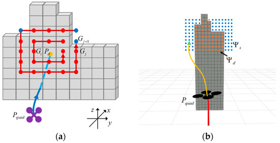
Figure 3.
Expanded space observer’s second observation (planar expanded observation): (a) the front view of the planar expanded observation process; (b) simulation results of the planar expanded observation.
By performing depth observation and expanded observation, UAVs can extract 3D-to-2D information for obstacles of any angle and shape. This facilitates setting local target points for subsequent flight, as shown in Figure 4a–f. Simultaneously, based on whether all areas within the observation plane are unsafe, determine the size of obstacles. As shown in Figure 4g, the obstacle is identified as a small-sized one, while in Figure 4h it is classified as a large-sized one.
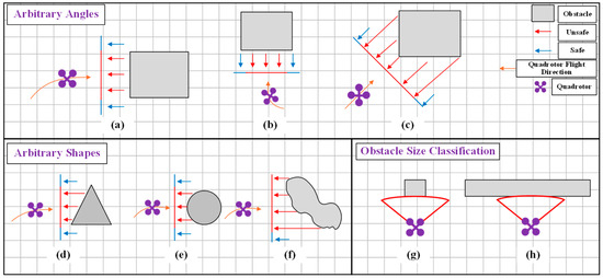
Figure 4.
Schematic of the expanded space observer’s performance in multiple scenarios. (a–c) UAVs approach obstacles from arbitrary angles; (d–f) UAVs approach obstacles of arbitrary shapes; (g,h) Obstacles are classified by size.
2.1.2. TD3 Local Target Point Generation Algorithm
This paper employs a deep reinforcement learning algorithm to generate local target points within the local safe region output in Section 2.1.1. By combining the current status of the UAV, obstacle information, and flight mission, the algorithm outputs reasonable local target points and path memory points. For small-sized obstacles, only a local target point need to be generated. For large-sized obstacles, a path memory point is additionally generated after producing the local target point . Path memory points and local target points represent two distinct guidance directions, as illustrated in Figure 5, which must satisfy the constraint condition . This constraint enables the system to fall back to the path memory point when the guidance direction at the local target point fails to meet obstacle avoidance requirements for large-sized obstacles, thereby completing the avoidance via an alternative route.
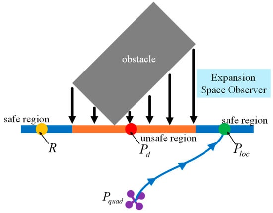
Figure 5.
Schematic of a local target point and a path memory point.
The algorithm employs the TD3 algorithm, which incorporates twin critic networks, delayed policy updates, and target policy smoothing. These optimize the problem of Q-value overestimation and enhance training stability, making the approach suitable for solving continuous control problems. The TD3 algorithm employs two independent Critic networks to generate two action value and , and selects the smaller of the two to construct the target Q-value, in order to suppress overestimation:
where denotes the target Q-value, r signifies the immediate reward for the current state-action pair, while the discount factor serves to balance the importance of present rewards against future ones. The target policy network generates the target action in the next state , and gaussian noise is added to this action. Both and the noisy target action are then passed as inputs to the two target critic networks, and .The smaller of the Q-values from the two target critic networks is selected as the estimate for the next state-action pair, thereby mitigating overestimation issues. To ensure the stability of the actor network’s strategy, TD3 updates the actor network once after critic network updates twice, maximizing the Q-value through gradient ascent:
where the gradient direction of the actor network is obtained by computing the expectation over states sampled from the experience replay buffer , is the gradient of the critic network at the action , and denotes the gradient of the policy network with respect to its parameters . The TD3 algorithm takes the UAV’s state, obstacle information, and flight mission as inputs to output local target points. The network model is shown in Figure 6.
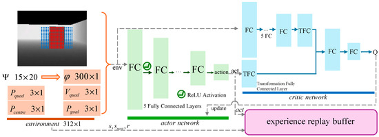
Figure 6.
Network struct for local target point generation.
The observation space, action space, and reward function are defined as follows:
(1) The observation space: A reasonable local target point needs to comprehensively consider obstacle information, the current flight status of the UAV, and the global flight mission. The extended space observer in Section 2.1.1 provides obstacle information and can calculate the obstacle center point . The observation plane is divided into a 15 × 20 grid. Grid cells within the local safe region are marked as 0, indicating no obstacles, while grid cells within the local unsafe region are marked as 1, indicating the presence of obstacles. This 15 × 20 matrix is then flattened row-wise into a 300 × 1 column vector . By observing the coordinates of the UAV and the coordinates of the global target point , the distance from the local target point to the UAV and global target point can be constrained. Monitoring the UAV’s current velocity helps determine the required velocity adjustment for navigating toward the local target point. Combining the above analysis, the final observation space is a 312 × 1 column vector, expressed as .
(2) The action space: The action output by the deep reinforcement learning network in this paper is defined as local relative coordinate , with the coordinate origin set at the , the final absolute coordinates of the local target point are . In order to avoid instability caused by excessive network dimensions and facilitate consideration of action value, the local target points output by deep reinforcement learning are generated within the observation plane . The also lies on the observation plane . Therefore, for the observation plane , the local target point coordinates are , where and represent the relative coordinates with respect to the . The final output local target point expression is:
(3) The reward function: A well-designed local target point must enable collision avoidance by guiding the UAV from its current position through the safe region , while preventing entry into unsafe regions . Additionally, the path needs to be as short as possible. Finally, the stability of the UAV velocity must be maintained, minimizing the dynamic output required to reach the local target point. Among them, the most important is path safety, so when the output action (local relative coordinate ) falls in unsafe regions , the current training ends with a reward . When the action is in a local safe area , the reward is:
The reward comprises three components: the safety term , path length increment , and velocity change . denotes the distance from the local target point to the nearest obstacle. The second term represents the path length increment after passing the local target point, and it is calculated as the distance from the UAV’s arrival at the local target point to the global destination minus the straight-line distance from the UAV’s current coordinates to the global destination. The third term is calculated as the UAV’s current velocity minus the simulated velocity for the next stage . The weights , , and determine the relative importance of each reward component. Through the reward function (5), the UAV can maintain a safe distance from obstacles while adopting shorter paths and smoother velocity adjustments, thereby enhancing flight stability during obstacle avoidance.
2.2. Path Optimization Algorithm
2.2.1. SDC-Minimum Snap
Based on the local target point generated in Section 2.1, it is necessary to establish and optimize the path from the current position of the UAV to the local target point. For the classic Minimum Snap path optimization algorithm, smooth path can be generated by minimizing the integral of the snap squared. However, its differential constraints at path endpoints are hard constraints. Before the trajectory equation is generated, only the zero-order derivative at the path endpoint (the position of the local target point ) can be determined, while the first-order derivative and higher-order derivatives (the velocity and acceleration of the local target point) are often unknown. A conventional approach is to set the first-order derivative at the path endpoint to (where denotes the global target point and denotes the maximum velocity limit), while the acceleration at the path endpoint is set to zero. Such heuristic assignments for unknown states and treating them as hard constraints, leads to paths exhibiting unnecessary curvature in order to accommodate unreasonable terminal differential terms. This may result in aggressive control inputs and reduce UAV flight speed. To enhance the coupling between UAV velocity and trajectory, this paper refines the conventional Minimum Snap algorithm. The higher-order differential terms at the path endpoint are no longer treated as hard constraints but are instead optimized as penalty terms alongside the path parameters. This allows for adaptive adjustment based on the path, as illustrated in Figure 7. Here, the path using the hard constraint of the end differential term is denoted as , and the path using the soft constraint of the end differential term is denoted as . The path can adaptively adjust the end velocity and acceleration within a certain range and , better balancing the constraints at the end of the path and the curvature of the path. Through the adaptation of the terminal differential term, the SDC-Minimum Snap in this paper can output a path that satisfies the UAV to fly through at a faster speed.
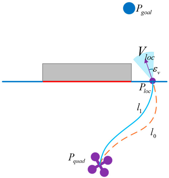
Figure 7.
Comparison diagram of path generation schemes.
Considering a trajectory composed of M polynomial segments, the Nth order polynomial of each segment path can be described as Equation (6), and the trajectory parameter vector C to be optimized is shown in Equation (7).
where is the flight time of the UAV, and is the end time of the previous path segment. For M-segment polynomial trajectory, the optimization model of SDC-Minimum Snap is shown in Equation (8):
where represents the penalty term for the square of the fourth-order derivative of the path, denotes the penalty term for the soft constraints on the terminal derivatives of the trajectory, and is the soft constraint weight coefficient that balances the and . In SDC-Minimum Snap, the differential terms at the path endpoints are no longer treated as hard constraints within the optimization model but are instead optimized as penalty terms. For , its mathematical expression is given by:
where is the parameter vector for the i-th trajectory segment, which corresponds to in Equation (7); is the cost matrix for the i-th segment with respect to time t, and Q is the overall cost matrix for the M segments.
The penalty term for the soft constraints on the terminal derivatives of the trajectory comprise the endpoint velocity penalty term and the endpoint acceleration penalty term. The velocity and acceleration at the trajectory endpoint are expressed, respectively, by Equations (10) and (11):
where T denotes the total trajectory duration. To facilitate subsequent term grouping and solver optimization, we construct the terminal velocity selection vector , whose function is to select parameters from the trajectory parameter vector C for use in the terminal velocity expression, where the i-th term is as shown in Equation (12). Similarly, for terminal acceleration, we construct the acceleration selection vector , where the i-th term is as shown in Equation (13). By multiplying the velocity selection vector (12) and the acceleration selection vector (13) with Equations (10) and (11), respectively, the expressions for the velocity and acceleration at the end of the path (the m-th segment of the path) are given by Equations (13) and (14):
Subtracting the terminal velocity from the target velocity and the terminal acceleration from the target acceleration, then squaring each difference, the is expressed as:
where and are the preset values of velocity and acceleration at the terminal trajectory, and are weight parameters. Since the terminal velocity and acceleration are typically unknown before the trajectory parameters are generated, a common practice is to assume that points toward the global target point with a magnitude equal to the maximum speed limit, and is assumed to 0. These assumed values at the terminal trajectory does not need to be treated as hard constrains. Instead, a certain degree of freedom should be given to them, so that the optimizer can adaptively adjust the terminal derivatives to generate a smoother trajectory. Formula (16) is derived from this idea. Finally, combining Formula (9) with Formula (16) and removing the constant term yields the final optimized model:
For Equation (17), the path parameter C can be obtained by solving under the conditions of satisfying the continuity constraints of the internal points of the trajectory and the higher-order derivative constraints of the starting point (position, velocity, acceleration). The first and second-order constraints at the path endpoint are no longer treated as hard constraints in the solution process. Instead, they are implemented as implicit constraints via penalty terms, allowing the solver to optimally adapt the terminal velocity and acceleration.
In the SDC-Minimum Snap algorithm, the weight coefficients include the soft constraint weight coefficient , velocity weight coefficient , and acceleration weight coefficient . Here, is used to balance and , while and adjust the weights of velocity and acceleration within .The empirical range for is , derived based on the matrix spectral norm ratio , where . By selecting an appropriate value, and are numerically comparable in the optimization. It should be noted that leads to numerical instability in the solver, while effectively disables the soft constraints, causing the formulation to degenerate to an unconstrained Minimum Snap and introducing uncertainty in the terminal trajectory. The ranges for and can be obtained based on the allowable adjustment range. The core principle of this approach is that the weight coefficient and are inversely proportional to the square of the maximum allowable adjustment ranges, formulated as and , where and are the maximum adjustable ranges for velocity and acceleration, respectively (e.g., , ). When the allowable adjustment ranges and are smaller, the corresponding weight coefficients and become larger, thereby increasing the tracking accuracy for the terminal derivatives in the solution. The empirical ranges for both and are .
For actual path solving, if the initially generated trajectory collides with obstacles, the expanded space observer is performed on the colliding obstacle to generate a second trajectory. In Figure 8a, the expanded space observer produces a local target point , and a corresponding path is generated using the SDC-Minimum Snap algorithm. Upon inspection, the trajectory collides with an obstacle. Therefore, the expanded space observer is conducted again in the vertical direction of the collision trajectory. The second local target point generated through the expanded space observer is , as shown in Figure 8b. Based on and , the SDC-Minimum Snap method generates a final executable trajectory , ultimately achieving successful obstacle avoidance and secure flight.
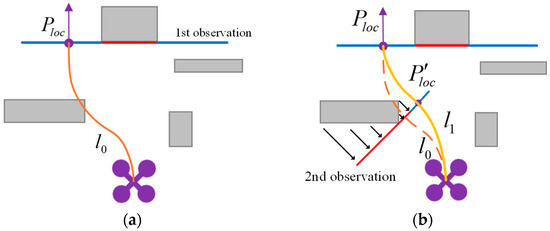
Figure 8.
Trajectory security optimization solution: (a) the initially trajectory; (b) the final executable trajectory.
2.2.2. Path Memory Point Backtracking Algorithm
During flight, each time the UAV encounters a large-sized obstacle, it generates a path memory point and stores it in the path memory sequence . By backtracking path memory points, the UAV can optimize its path planning process, thereby avoiding getting stuck in local optima or wandering back and forth without finding a viable path when navigating around large-sized obstacles.
The local optimal solution for large-sized obstacles is essentially due to limitations in UAV environmental perception, including restricted sensing range, limited field of view, and occlusions. This results in the UAV being unable to fully perceive obstacles and relying solely on limited information to make plans, ultimately falling into the dilemma of local optimal solutions. Two typical scenarios are shown in Figure 9. Figure 9a shows a long straight obstacle. When the UAV cannot detect the full extent of the obstacle, the generated local path points may guide the UAV into a non-optimal path. In Figure 9b, the obstacles are large-sized structures with corners. In such cases, it is difficult for the UAV to directly output a detour path for corner obstacles.
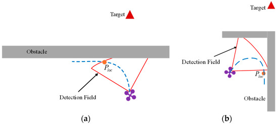
Figure 9.
Typical large-sized obstacle scenarios: (a) Long straight large-sized obstacle; (b) Large-sized corner obstacle.
To optimize path planning methods for large-sized obstacles, this study proposes a path memory point backtracking algorithm. Upon detecting an obstacle, the UAV initiates the path memory point backtracking algorithm if the obstacle is large. Obstacle size analysis is performed by the expanded space observer described in Section 2.1.1. The path cost function for the local target point is:
The function represents the sum of the distance from the local target point to the UAV position and the distance to the global target point . Here, and denote the corresponding weights. The backtracking cost for each position in the path memory point sequence is obtained by multiplying its own path cost function by a dynamically changing coefficient . Here, there are two main requirements for the dynamically changing coefficient : (1) When the UAV faces a large-sized obstacle, it should be encouraged to further explore the current large-sized obstacle at the initial moment, so the coefficient should be set to a relatively high value at the initial moment; (2) when the UAV faces a large-sized obstacle and has already paid enough cost but still cannot navigate, the coefficient should be reduced to guide the UAV to backtrack the path memory points. In this regard, the backtracking cost function for path memory point and its dynamic coefficient are formulated as:
where represents the path cost of the path memory point itself, which is obtained from Equation (18). In the dynamic coefficient , denotes the upper asymptote of the dynamic coefficient, represents the slope of the dynamic coefficient change, and indicates the turning point of the dynamic coefficient. When the path cost paid by the UAV exceeds , the cost of backtracking decreases rapidly. Here, the nonlinear variation of initially encourages the UAV to follow the direction guided by the original local target point , and later correct its flight direction to backtrack to the path memory points.
When encountering large-sized obstacles, if the backtracking cost of the UAV’s path memory point is less than the cost of the current local target point , the UAV will backtrack the path memory point. The backtracking procedure temporarily sets as the global target point and executes the path planning algorithm described in this paper. For the long straight and large-size obstacles in Figure 9a, the schematic diagram of the detour route through the path memory point is shown in Figure 10a. After the UAV detects obstacles, it generates a local path point and a path memory point . Upon reaching , the UAV outputs a new local path point . Since this is a large-sized obstacle, the backtracking cost for the path memory point is calculated. When the backtracking cost of the path memory point is less than the cost of the new local target point , the UAV starts to backtrack the , and finally completes the detour of the obstacle and proceeding toward the final target. For the corner large-size obstacle in Figure 9b, the schematic diagram of the detour route is shown in Figure 10b. The expanded space observer generates local path point and path memory point . As the UAV gradually flies guided by , the dynamic coefficient of path memory point gradually decreases. When the cost of backtracking becomes lower than the cost of local target point , the UAV begins backtracking and ultimately completes the obstacle detour.
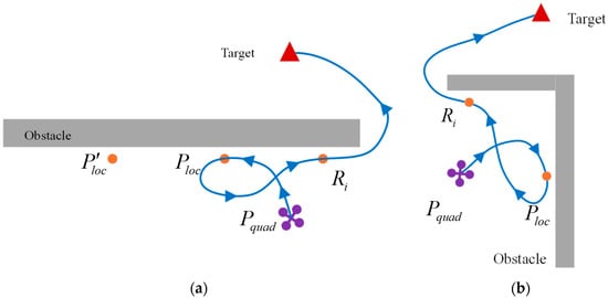
Figure 10.
Path memory points backtracking: (a) schematic diagram of long straight obstacle backtracking; (b) schematic diagram of large-sized corner obstacle backtracking.
3. Results
3.1. Path Planning Simulation Experiments
In the simulation experiments, this paper constructs high-density obstacle scenarios and large-sized obstacle scenarios to validate the feasibility and performance of the proposed algorithm. To ensure experimental fairness, key parameters are defined as follows: maximum velocity = 2 m/s, maximum acceleration = 3 m/s2, maximum jerk = 6 m/s3, algorithm step size = 0.1 s, obstacle inflation = 0.2 m, safety redundancy = 0.15 m, detection angle = and detection range = 3 m.
This paper presents four high-density obstacle scenario maps. The path planning comparison results for maps 1 to 4 are shown in Figure 11. The distance between the start points and the end points is 38 m, including an obstacle area of 30 m × 20 m. The obstacles in the map include randomly distributed cubes and rings. The density of obstacles from map 1 to map 4 gradually increases, and the size of cube obstacles is uniformly set at 0.6 m × 0.6 m × 3 m, while the diameter of the ring is 0.6~0.8 m. We compare Fast-Planner, Ego-Planner, and the proposed algorithm on Maps 1 to 4. The paths generated by Fast-Planner exhibit a tendency to diverge laterally, particularly in Map 2, which leads to a reduction in path efficiency. Although Ego-Planner shows improved path efficiency, it employs extensive turning maneuvers during continuous obstacle avoidance, thereby compromising path smoothness. The proposed algorithm successfully avoids obstacles while maintaining a path that closely aligns with the straight line from start points to end points. The generated path demonstrates effective convergence and suppresses lateral divergence, resulting in a more efficient path compared to the other two algorithms.
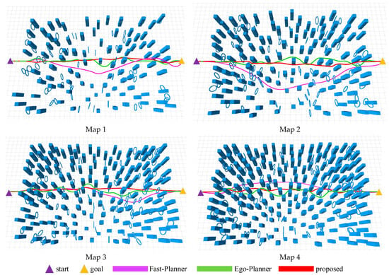
Figure 11.
Comparison of Path Planning Methods in High-Density Obstacle Scenarios. Map 1: 90 cubes and 60 rings; Map 2: 120 cubes and 80 rings; Map 3: 150 cubes and 100 rings; Map 4: 180 cubes and 120 rings.
The size of obstacles also has a significant impact on the success rate of path planning for UAVs. Currently, more researchers are focusing on high-density obstacle scenarios to verify continuous and flexible obstacle avoidance capabilities. However, few researchers have considered the impact of obstacle size on the success rate of path planning. This experiment set up large-scale obstacle scenarios maps 5 and 6, with obstacle sizes of 5 m and 8 m, respectively. The experimental results are shown in Figure 12. In map 5, both the Ego Planner and the proposed algorithm successfully completed flight tasks when encountering a 5 m obstacle. The Fast Planner, however, failed to generate the next flight path segment when the obstacle size exceeded the UAV perception range, resulting in planning failure and program termination before the large obstacle. When the obstacle size increased to 8 m, the proposed algorithm successfully completed the flight task. This capability attributed to the cost function calculation (19) for path memory points: when the cost of the current local target point exceeds that of a path memory point, the algorithm selects the path memory point for backtracking, enabling escape from the L-shaped obstacle’s corner. In contrast, the two compared planning algorithms are unable to generate effective paths when facing large-sized obstacles, resulting in direct termination or wandering in front of obstacles, leading to planning failure or reduced path efficiency. Through this experiment, it can be concluded that the proposed algorithm exhibits strong path planning performance in scenarios with large-sized obstacles.
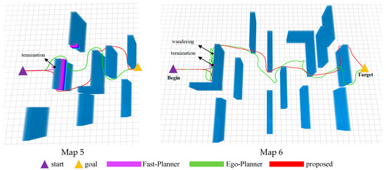
Figure 12.
Comparison of path planning methods for large-sized obstacle scenarios. Map 5: obstacle size 5 m; Map 6: obstacle size 8 m.
Furthermore, the comparison of flight speed distribution for Maps 1 to 6 is shown in Figure 13, while Table 1 presents the detailed experimental results for these maps. The flight speed data in Figure 13 can be analyzed in terms of maximum speed, minimum speed, the interquartile range, and the median speed. Fast-Planner exhibits lower minimum and average speeds, which can be attributed to its more conservative obstacle avoidance strategy. This approach results in paths that are more curved and have shorter straight segments, thereby reducing its average speed. EGO-Planner demonstrates narrower interquartile ranges across most maps, indicating considerable speed stability. However, it tends to generate multiple paths with high curvature when navigating consecutive obstacles, limiting increases in both average and maximum speeds. The proposed algorithm employs an improved SDC-Minimum Snap, achieves a balance between path curvature and flight speed during obstacle avoidance. This is accomplished through adaptive end-point adjustment and the selection of local target points that incorporate the UAV current flight speed. This results in more straight path segments, allowing for a higher maximum speed and maintaining a favorable average speed.
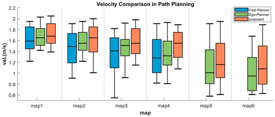
Figure 13.
Comparison of flight speed distribution.

Table 1.
Experiment results of path planning for Map 1 to Map 6.
According to the analysis data in Table 1, the success rate refers to the number of times the planned path reaches the target while fully complying with dynamic constraints, divided by the total number of experiments. Path efficiency refers to the straight-line distance from the starting point to the endpoint divided by the actual flight distance of UAVs. The higher the path efficiency, the shorter the detour distance in the path. The safety distance represents the closest distance between UAVs and expanded obstacles during flight. Path energy is measured as the integral of the squared jerk. As shown in Table 1, the proposed algorithm achieves a high success rate across varying obstacle densities and sizes. In high-density and large-size obstacle scenarios, the success rates exceed 91% and 82%, respectively. The algorithm also delivers satisfactory performance in terms of path efficiency, demonstrating strong path convergence capability. EGO Planner’s path planning is the safest in most scenarios and can always maintain a safe distance from obstacles. In maps 5 and 6, despite facing large obstacles and wandering back and forth, it can still maintain a safe distance of 0.20 m from the obstacles. In terms of flight time , the proposed algorithm completes missions faster, owing to its higher flight speed and more efficient path planning. In contrast, Fast-Planner demonstrates lower path energy consumption. This is mainly due to the Fast-Planner’s avoidance of high maneuverability actions such as sharp turns, but this also leads to a decrease in its path efficiency, resulting in excessive lateral deviations in the trajectory. In contrast, the proposed algorithm achieves a favorable balance between path energy and flight maneuverability. Based on the experimental data and analysis above, the proposed method demonstrates effective path planning in both high-density and large-sized obstacle scenarios, while completing flight tasks with greater efficiency and speed.
3.2. Real-World Experiments
The experiment quadrotor testbed is shown as Figure 14. The main hardware components include: an Intel NUC 13 i5-1340p processor (Intel Corporation, Santa Clara, CA, USA) as the onboard computer, a Pixhawk 6C mini (Holybro Technology Limited, Shenzhen, Guangdong, China) as the flight control processor, and an Intel D435i (Intel Corporation, Santa Clara, CA, USA)as the visual perception sensor. The UAV frame is model 550, with propeller dimensions of 0.95 m (length) × 0.95 m (width) × 0.35 m (height), and a total weight of 1.5 kg. In the absence of prior maps, the UAV perceives the environment in real-time through the D435i visual senso, and completes path planning on the onboard computer.
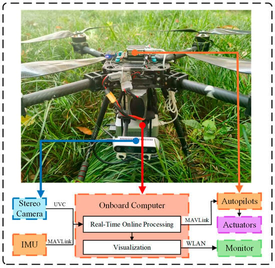
Figure 14.
Experiment quadrotor testbed.
This paper conducted comparative experiments in both high-density obstacle scenarios and large-sized obstacle scenarios. Figure 15 shows the testing site and flight data for high-density obstacle experiments, while the large-sized obstacle scenarios are presented in Figure 16. Table 2 presents detailed experimental data for the two scenarios.
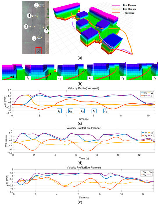
Figure 15.
Real-World experiments in high-density obstacle scenarios: (a) Experimental site and path planning results; (b) Detailed visualization of the proposed method; (c) Velocity profile of the proposed method; (d) Velocity profile of Fast-Planner; (e) Velocity profile of Ego-Planner.
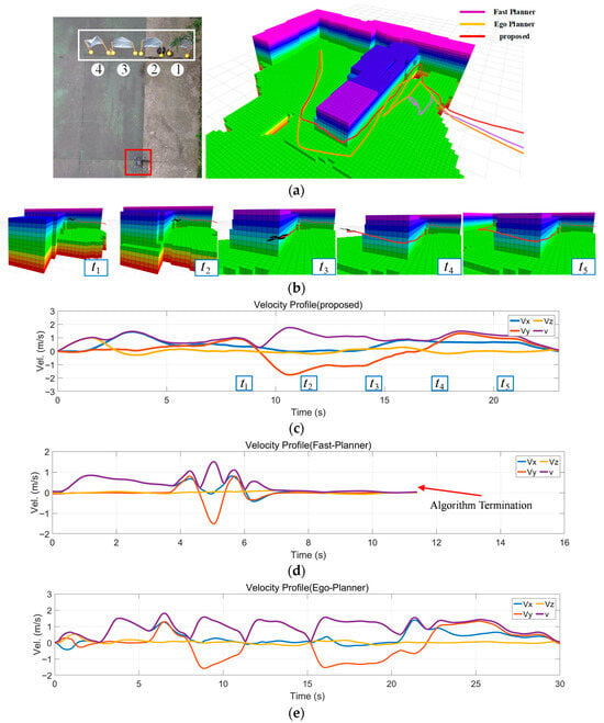
Figure 16.
Real-World experiments in large-sized obstacle scenarios: (a) Experimental site and path planning results; (b) Detailed visualization of the proposed method; (c) Velocity profile of the proposed method; (d) Velocity profile of Fast-Planner; (e) Velocity profile of Ego-Planner.

Table 2.
Comparative Analysis of Method Performance.
In high-density obstacle scenarios experiments, the testing area measures 12 m (length) × 5 m (width). Among them, the distance between adjacent obstacles less than 1.6 m, and the length and width of the UAV itself are about 1 m. The testing site and the comparison of path planning results are shown in Figure 15a. The details of our method are presented in Figure 15b, and the velocity profile of the three algorithms are shown in Figure 15c–e, respectively. Experimental results show that the algorithm proposed in this paper can achieve an average flight speed of 1.50 m/s, while the two compared algorithms have average flight speeds of 1.23 m/s and 1.31 m/s. Furthermore, based on the data in Table 2, although the Fast-Planner has a better path energy and reduces jerk’s output, the flight path of our algorithm is the shortest of only 13.58 m. This indicates that the proposed method achieves higher path efficiency by employing greater energy output to track faster-converging paths, thereby minimizing lateral path divergence. Based on the above analysis, the proposed method demonstrates superior flight speed and optimal path selection, enabling more efficient completion of flight tasks.
For the large-size obstacle scenarios experiment, the experimental site and path planning comparisons are shown in Figure 16a. Figure 16b is details the path planning of the proposed method, and Figure 16c–e are the velocity profile diagrams of the three methods. Experiments demonstrate that due to the UAV’s perception range being smaller than the obstacle size, the output local target points may guide the UAV toward corners. To address this, the proposed method achieves obstacle avoidance by path memory points backtracking. However, due to the perception distance being smaller than the obstacle size, Fast-Planner cannot generate a feasible path and thus terminates the algorithm. Meanwhile, EGO-Planner struggles to plan a safe trajectory when confronting large obstacles, resulting in wandering before the large-sized obstacles.
Based on the data in Table 2 and the above experiments, a more comprehensive analysis of the three methods can be conducted. Among them, Fast-Planner demonstrates favorable path energy consumption in high-density obstacle scenarios, but it sacrifices path efficiency (the flight path is the longest among the three methods) and is difficult to operate in large-sized obstacle scenes. EGO-Planner exhibits high safety performance, achieving longest safety distances of 0.32 m and 0.20 m in the two experimental scenarios, respectively. When encountering large-sized obstacles, the proposed method can quickly and systematically execute obstacle avoidance maneuvers. The experimental data above validates the algorithm’s general path planning capabilities in both high-density obstacle scenarios and large-sized obstacle scenarios, demonstrating its effectiveness in completing flight missions with greater efficiency and speed.
4. Discussion
Currently, researchers focus more on the performance of UAVs path planning algorithms in high-density obstacle scenarios, but rarely consider scenarios with large-sized obstacles. This paper proposes a general path planning algorithm for high-density obstacle scenarios and large-sized obstacle scenarios, and improves path efficiency and flight speed. When encountering large-sized obstacles (such as long straight obstacles or L-shaped obstacles), traditional path search algorithms struggle to find feasible detour paths because onboard sensors cannot directly observe the obstacle’s entire outline. To address this, this paper establishes reasonable local target points to guide the UAV flight direction in both high-density and large-sized scenarios, thereby achieving general path planning capability. Moreover, the expanded space observer and the improved SDC-Minimum Snap algorithm enhance the UAV path efficiency and flight speed, respectively. The proposed algorithm has been validated through both simulation and real-world experiments in high-density and large-obstacle scenarios. In this section, we will discuss its performance in terms of generality, path efficiency, and flight speed.
(1) Generality: Current path planning for UAVs has been significantly optimized in high-density obstacle scenarios, such as autonomous flight in forest environments. However, scenarios involving large-sized obstacles has received little attention. In high-density obstacle scenarios, since the onboard sensors of UAVs can directly observe the contours of obstacles, a collision free detour path can be obtained through the front-end path search algorithm. In contrast, when facing large obstacles (e.g., L-shaped barriers), the onboard sensors struggle to capture the full contour of the obstacle at first sight. As a result, the front-end search often fails to produce a feasible detour, leading to planning failure. Through experimental analysis, in high-density obstacle scenarios—such as those shown in simulation Figure 11 and real-world experiment Figure 15—all the three methods can complete path planning, and the proposed method achieves the highest average success rate of 94.5%. However, for large-sized obstacle scenarios, such as Figure 12 in simulation experiments and Figure 16 in real-world experiments, the two comparison algorithms have the problem of wandering back and forth or even program termination, resulting in path planning failure. In contrast, the proposed algorithm demonstrates better detour capability. This is because the proposed method guides the flight path through reasonable local target points in both obstacle scenarios. In large-obstacle scenarios, it employs local target points and path memory points in two guidance directions. When local target points cannot complete the detour, a dynamically updated cost function enables a backtracking flight to the path memory points, thereby achieving obstacle avoidance and orderly flight before large obstacles.
(2) Path efficiency: Path efficiency is an important indicator for measuring the quality of path planning algorithms for UAVs. In this paper, path efficiency comparisons are conducted by calculating the ratio of the UAV’s actual flight distance to the straight-line distance between the starting point and the endpoint. This paper proposes an expanded space observer. Through two observations, it ensures that when a UAV approaches obstacles of arbitrary shapes at any angle, a local safe zone adjacent to the obstacle can be generated. This accelerates path convergence during obstacle avoidance. Experimental results show that in high-density obstacle scenarios, the average path efficiency of the proposed method reaches 95.25%; In large-sized obstacle scenes, the average path efficiency has increased by 19% compared to the comparative method. Further analysis reveals that for single-obstacle avoidance, path efficiency and safety distance often exhibit a negative correlation. For instance, the EGO-Planner in Table 1 and Table 2 maintains a stable safety distance of 0.2 to 0.3 m despite suboptimal path efficiency. However, it should be pointed out that for the avoidance of continuous obstacles, path efficiency is not only related to the safe distance. The algorithm’s choice of global planning direction often has a greater impact on path efficiency. Therefore, further examination of Figure 11, Figure 12 and Figure 15 reveals that the proposed method better captures the global path planning direction, enabling shorter flight path and thereby enhancing flight path efficiency.
(3) Flight speed: The flight speed of UAV is closely related to the back-end path optimization, especially the smoothness of the path and the differential constraints (speed, acceleration) at the path endpoint. Before generating the path equation, only the position coordinates of the endpoint are clearly known, while the optimal values for velocity and acceleration at the endpoint are often difficult to determine. A common approach adopted by many algorithms is to heuristically assign values to the endpoint velocity and acceleration. Typically, the terminal velocity vector is assumed to point toward the global target point with magnitude equal to the UAV maximum dynamic velocity, while acceleration is directly set to zero. In the classic Minimum Snap algorithm, these hypothetical terminal differential terms are treated as hard constraints to optimize and solve for path parameters. However, these hypothetical differential terms are usually not the optimal values, and using them as hard constraints reduce the degree of path parameter optimization, thereby reducing the flight speed of UAVs. To address this, our paper enhances the coupling between velocity and path parameters, proposing the SDC-Minimum Snap algorithm. By co-optimizing the endpoint differential terms and path parameters within an adaptive range, our method better balances endpoint velocity/acceleration and path curvature, ultimately improving flight speed. Through comparative experiments, the average flight speed was improved by 8.16% and 19.40% compared to the comparative algorithm in high-density obstacle scenes and large-sized obstacle scenes, respectively.
5. Conclusions
This paper proposes a general path planning algorithm for UAV in high-density obstacle scenarios and large-sized obstacle scenarios. For both obstacle scenarios, the algorithm achieves unified framework implementation by guiding the UAV flight direction through the establishment of reasonable local target points. In large-obstacle scenarios, the planning of detour paths is accomplished through path memory points and a backtracking algorithm. On the front end, we propose an extended space observer. Through two observations, it can identify obstacle dimensions and generate safe regions—regardless of the UAV approach angle or the obstacle’s shape. Combined with deep reinforcement learning, local target points can be generated within the safe regions to guide the direction of UAV flight. On the back end, we propose an improved SDC-Minimum Snap algorithm. It enables the co-optimization of path parameters and the differential terms at the path endpoint, allowing adaptive tuning of endpoint velocity and acceleration relative to the path shape. This improves the overall flight speed. Analysis of experimental data reveals that the proposed algorithm achieves an 8.16% increase in flight speed and a 19% improvement in path efficiency compared to the baseline algorithm. Through simulations and real-world experiments, the algorithm’s generality and feasibility in high-density obstacle scenarios and large-sized obstacle scenarios are validated.
In the future, we plan to focus on UAV path planning in dynamic scenarios as our next research direction. For dynamic environments, this primarily involves motion object detection, motion intent recognition, and joint optimization across temporal and spatial domains. Motion object detection can be achieved through image-based semantic segmentation or kinematics-based clustering algorithms. Motion intention recognition will be achieved by analyzing historical velocity estimates and conducting probabilistic inference. Finally, the planning process will integrate both temporal and spatial dimensions to generate and optimize UAV trajectories in dynamic settings. The proposed algorithm lays a crucial foundation for future studies on dynamic scenarios. Building upon this work, we will further expand our framework, conduct in-depth analysis of dynamic environments, and incorporate them as new research topics into our future research roadmap.
Author Contributions
Conceptualization, J.C. and X.L.; methodology, J.C. and X.L.; software, G.S.; validation, J.C. and B.Z.; formal analysis, Q.S.; investigation, J.C. and X.L.; resources, G.S.; data curation, J.C.; writing—original draft preparation, J.C.; writing—review and editing, Q.S.; visualization, J.C.; project administration, J.C. and X.L.; funding acquisition, X.L. All authors have read and agreed to the published version of the manuscript.
Funding
This research was funded by the Jiangsu Provincial Frontier Technology Research and Development Program of China under Grant BF2024072.
Data Availability Statement
The data presented in this study are available on request from the corresponding author.
Conflicts of Interest
The authors declare no conflicts of interest.
References
- Qiu, J.; Liu, Q.; Qin, J.; Cheng, D.; Tian, Y.; Ma, Q. PE-Planner: A Performance-Enhanced Quadrotor Motion Planner for Autonomous Flight in Complex and Dynamic Environments. IEEE Robot. Autom. Lett. 2024, 9, 5879–5886. [Google Scholar] [CrossRef]
- Debnath, D.; Vanegas, F.; Sandino, J.; Hawary, A.F.; Gonzalez, F. A Review of UAV Path-Planning Algorithms and Obstacle Avoidance Methods for Remote Sensing Applications. Remote Sens. 2024, 16, 4019. [Google Scholar] [CrossRef]
- Lindqvist, B.; Patel, A.; Löfgren, K.; Nikolakopoulos, G. A Tree-Based Next-Best-Trajectory Method for 3-D UAV Exploration. IEEE Trans. Robot. 2024, 40, 3496–3513. [Google Scholar] [CrossRef]
- Wang, P.; Tang, J.; Lin, H.W.; Zhang, F.; Wang, C.; Wang, J.; Shi, L.; Meng, M.Q.H. MINER-RRT*: A Hierarchical and Fast Trajectory Planning Framework in 3D Cluttered Environments. IEEE Trans. Autom. Sci. Eng. 2025, 22, 10973–10985. [Google Scholar] [CrossRef]
- Chen, G.; Peng, P.; Zhang, P.; Dong, W. Risk-Aware Trajectory Sampling for Quadrotor Obstacle Avoidance in Dynamic Environments. IEEE Trans. Ind. Electron. 2023, 70, 12606–12615. [Google Scholar] [CrossRef]
- Liu, S.; Guo, K.; Yu, X.; Ma, L.; Xie, L.; Guo, L. Safe Maneuvering Planning for Flights in Complex Environments. IEEE Trans. Ind. Electron. 2024, 71, 4944–4953. [Google Scholar] [CrossRef]
- Gao, Y.; Ji, J.; Wang, Q.; Jin, R.; Lin, Y.; Shang, Z.; Cao, Y.; Shen, S.; Xu, C.; Gao, F. Adaptive Tracking and Perching for Quadrotor in Dynamic Scenarios. IEEE Trans. Robot. 2024, 40, 499–519. [Google Scholar] [CrossRef]
- Lee, G.; Kim, K.; Jang, J. Real-time path planning of controllable UAV by subgoals using goal-conditioned reinforcement learning. Appl. Soft Comput. 2023, 146, 110660. [Google Scholar] [CrossRef]
- Zhou, X.; Tang, Z.; Wang, N.; Yang, C.; Huang, T. A novel state transition algorithm with adaptive fuzzy penalty for multi-constraint UAV path planning. Expert Syst. Appl. 2024, 248, 123481. [Google Scholar] [CrossRef]
- Zhang, X.; Lu, J.; Hui, Y.; Shen, H.; Xu, L.; Tian, B. RAPA-Planner: Robust and Efficient Motion Planning for Quadrotors Based on Parallel RA-MPPI. IEEE Trans. Ind. Electron. 2025, 72, 7149–7159. [Google Scholar] [CrossRef]
- Conti, F.C.; Santoro, C.; Santoro, F.F. Twinflie: A Digital Twin UAV Orchestrator and Simulator. In Proceedings of the 2023 IEEE Intl Conf on Dependable, Autonomic and Secure Computing, Intl Conf on Pervasive Intelligence and Computing, Intl Conf on Cloud and Big Data Computing, Intl Conf on Cyber Science and Technology Congress (DASC/PiCom/CBDCom/CyberSciTech), Abu Dhabi, United Arab Emirates, 14–17 November 2023; IEEE: New York, NY, USA, 2023; pp. 258–263. [Google Scholar]
- Li, Y.; Dong, X.; Ding, Q.; Xiong, Y.; Liao, H.; Wang, T. Improved A-STAR Algorithm for Power Line Inspection UAV Path Planning. Energies 2024, 17, 5364. [Google Scholar] [CrossRef]
- Yao, H.; Liang, X. Autonomous Exploration Under Canopy for Forest Investigation Using LiDAR and Quadrotor. IEEE Trans. Geosci. Remote Sens. 2024, 62, 1–19. [Google Scholar] [CrossRef]
- Kim, S.; Kim, M.; Kim, Y. Fault-Tolerant Adaptive Control for Trajectory Tracking of a Quadrotor Considering State Constraints and Input Saturation. IEEE Trans. Aerosp. Electron. Syst. 2024, 60, 3148–3159. [Google Scholar] [CrossRef]
- Zhang, H.; Huo, J.; Huang, Y.; Wang, D. Perception-Aware Based Quadrotor Translation and Yaw Angle Planner in Unpredictable Dynamic Situations. IEEE Trans. Aerosp. Electron. Syst. 2025, 61, 47–60. [Google Scholar] [CrossRef]
- Zhang, J.; Zhu, X.; Li, J. Intelligent Path Planning with an Improved Sparrow Search Algorithm for Workshop UAV Inspection. Sensors 2024, 24, 1104. [Google Scholar] [CrossRef]
- He, Y.; Wang, M. An improved chaos sparrow search algorithm for UAV path planning. Sci. Rep. 2024, 14, 366. [Google Scholar] [CrossRef] [PubMed]
- Feng, J.; Sun, C.; Zhang, J.; Du, Y.; Liu, Z.; Ding, Y. A UAV Path Planning Method in Three-Dimensional Space Based on a Hybrid Gray Wolf Optimization Algorithm. Electronics 2024, 13, 68. [Google Scholar] [CrossRef]
- Gugan, G.; Haque, A. Path Planning for Autonomous Drones: Challenges and Future Directions. Drones 2023, 7, 169. [Google Scholar] [CrossRef]
- Yu, Q.; Qin, C.; Luo, L.; Liu, H.H.T.; Hu, S. CPA-Planner: Motion Planner With Complete Perception Awareness for Sensing–Limited Quadrotors. IEEE Robot. Autom. Lett. 2023, 8, 720–727. [Google Scholar] [CrossRef]
- Xing, S.; Xian, B.; Jiang, P. A Probabilistic Inference-Based Efficient Path Planning Method for Quadrotors. IEEE Trans. Ind. Electron. 2025, 72, 2810–2820. [Google Scholar] [CrossRef]
- Arul, S.H.; Sathyamoorthy, A.J.; Patel, S.; Otte, M.; Xu, H.; Lin, M.C.; Manocha, D. LSwarm: Efficient Collision Avoidance for Large Swarms With Coverage Constraints in Complex Urban Scenes. IEEE Robot. Autom. Lett. 2019, 4, 3940–3947. [Google Scholar] [CrossRef]
- Chipade, V.S.; Panagou, D. Multiagent Planning and Control for Swarm Herding in 2-D Obstacle Environments Under Bounded Inputs. IEEE Trans. Robot. 2021, 37, 1956–1972. [Google Scholar] [CrossRef]
- Li, J.; Xiong, Y.; She, J. UAV Path Planning for Target Coverage Task in Dynamic Environment. IEEE Internet Things J. 2023, 10, 17734–17745. [Google Scholar] [CrossRef]
- Zhang, X.; Xu, X.; Liu, Y.; Wang, H.; Zhang, X.; Zhuang, Y. FGIP: A Frontier-Guided Informative Planner for UAV Exploration and Reconstruction. IEEE Trans. Ind. Inform. 2024, 20, 6155–6166. [Google Scholar] [CrossRef]
- Wang, W.; Li, X.; Tian, J. UAV formation path planning for mountainous forest terrain utilizing an artificial rabbit optimizer incorporating reinforcement learning and thermal conduction search strategies. Adv. Eng. Inform. 2024, 62, 102947. [Google Scholar] [CrossRef]
- Lv, H.; Chen, Y.; Li, S.; Zhu, B.; Li, M. Improve exploration in deep reinforcement learning for UAV path planning using state and action entropy. Meas. Sci. Technol. 2024, 35, 056206. [Google Scholar] [CrossRef]
- Yu, J.; Shen, H.; Xu, J.; Zhang, T. ECHO: An Efficient Heuristic Viewpoint Determination Method on Frontier-Based Autonomous Exploration for Quadrotors. IEEE Robot. Autom. Lett. 2023, 8, 5047–5054. [Google Scholar] [CrossRef]
- Rekabi-Bana, F.; Hu, J.; Krajník, T.; Arvin, F. Unified Robust Path Planning and Optimal Trajectory Generation for Efficient 3D Area Coverage of Quadrotor UAVs. IEEE Trans. Intell. Transp. Syst. 2024, 25, 2492–2507. [Google Scholar] [CrossRef]
- Zhang, H.; Wang, S.; Liu, Y.; Ji, P.; Yu, R.; Chao, T. EFP: Efficient Frontier-Based Autonomous UAV Exploration Strategy for Unknown Environments. IEEE Robot. Autom. Lett. 2024, 9, 2941–2948. [Google Scholar] [CrossRef]
Disclaimer/Publisher’s Note: The statements, opinions and data contained in all publications are solely those of the individual author(s) and contributor(s) and not of MDPI and/or the editor(s). MDPI and/or the editor(s) disclaim responsibility for any injury to people or property resulting from any ideas, methods, instructions or products referred to in the content. |
© 2025 by the authors. Licensee MDPI, Basel, Switzerland. This article is an open access article distributed under the terms and conditions of the Creative Commons Attribution (CC BY) license (https://creativecommons.org/licenses/by/4.0/).