Highlights
What are the main findings?
- A fully autonomous, infrastructure-free UAV–UGV system for warehouse inventory is designed and validated: the UGV performs global localization via EKF + scan-to-map using only a 2D floor plan, while the UAV uses ArUco-based relative localization to autonomously take off, follow the UGV, and execute precision landings; results are validated in simulation and real-world trials.
- The proposed UGV localization yields consistently low translational error and the lowest orientation RMSE across scenarios, outperforming AMCL and remaining stable during a 45-min warehouse run where AMCL diverged; the UAV reliably follows and lands using a lightweight controller.
What are the implications of the main findings?
- Enables rapid, low-cost deployment in GPS-denied, symmetric warehouses without prior 3D mapping or external infrastructure, remaining robust to shelf-occupancy changes and dynamic clutter.
- Provides a practical path toward scalable cycle counting by coordinating UGV motion with UAV shelf scanning; the open-source implementation facilitates reproduction and adoption by industry and academia.
Abstract
Efficient and reliable inventory management remains a challenge in modern warehouses, where manual counting is time-consuming, error-prone, and costly. We present an autonomous aerial–ground system for warehouse inventory data capture that operates without external infrastructure or prior mapping operations. A differential-drive unmanned ground vehicle (UGV) performs global localization and navigation from a simple 2D floor plan via 2D LiDAR scan-to-map matching fused in an Extended Kalman Filter. An unmanned aerial vehicle (UAV) uses fiducial-based relative localization to execute short, autonomous take-off, follow, precision landing, and close-range imaging of high shelves. By ferrying the UAV between aisles, the UGV extends the UAV’s effective endurance and coverage, limiting flight to brief, high-value segments. We validate the system in simulation and real environments. In simulation, the proposed localization method achieves higher accuracy and consistency than AMCL, GMapping, and KartoSLAM across varied layouts. In experiments, the UAV reliably follows and lands on the UGV, producing geo-referenced imagery of high shelves suitable for downstream inventory recognition.
1. Introduction
The increased demand and competition in the e-commerce sector, where customers expect short delivery times, product availability, and shopping flexibility, pushes the need for greater efficiency and autonomy in warehouses [1]. One of the most crucial warehouse operations is inventory management. It is a fundamental component of the flow of services or goods from the point of origin to the point of consumption. Misinformation about the quantity, quality and location of each product present in the warehouse can break the supply chain and cause great expenses to all involved parties [2].
The warehouse inventory is usually physically checked annually. In this process, a human worker manually moves each item to scan its unique identifier and returns it [3]. This is a very repetitive and time-consuming process that is prone to human error. It can also take more than three days to complete an inventory check, during which other warehouse operations are blocked, which, added to the costly labor, makes it an expensive process. Furthermore, in larger warehouses, shelves can reach heights of at least 10 m, in which case the human worker must use specific stairs or machinery to reach the top shelves, increasing the risk of operation [4].
Robots can help automate warehouse tasks due to their ability to operate in environments that are dangerous or difficult to access [5,6,7]. However, single unmanned ground vehicles, UGVs, are limited by their reduced maneuverability and inability to reach high areas. In contrast, unmanned aerial vehicles, UAVs, offer greater mobility and access to elevated locations. However, their limited battery capacity restricts endurance, unlike UGVs, which can carry heavier batteries with minimal impact on performance. Thus, combining both platforms maximizes the agility of the UAV and the energy efficiency of the UGV, enabling more effective and robust inventory operations.
Some robotic solutions have already been commercially advertised for this task during the last decade. Solutions such as [8,9] propose using only UAVs while refs. [10,11] offer a UAV-UGV tethered system. Alternatively, Refs. [12,13] discard the UAV altogether and use UGVs with expandable telescopic towers that carry reading devices along the mast. However, this solution is costly, has limited scanning altitudes, and the stabilization of the mast is complex when the robot is moving [14].
One of the main challenges robots face in the warehouse environment is the localization, since indoor environments do not have reliable access to GNSS positioning systems and warehouses have highly symmetric and repetitive layouts with the addition of dynamic obstacles. Solutions like [15,16] face this challenge by placing ArUco markers in known positions across the space. Then, a drone carries a camera to detect these markers and obtain a global position measurement.
Obtaining the global markers’ position in the environment may be time-consuming and need to be repeated if the warehouse layout changes. Because of this, the navigation system of [17] places ArUco markers in the ground without knowing its global position. Their UAV uses an IMU, a LiDAR and a camera. The ArUco detection is used both for localization and loop closure. A key point of this system was to place the fiducial markers in areas where the LiDAR solution may be prone to failure. This requires strategic planning for each warehouse. The authors of [18] took a similar approach but without the use of LiDARs and the markers were placed equally through the warehouse, requiring no previous marker placement strategy.
Still, the installation of external objects can be time-consuming and may, overall, not be desired. Because of this, other solutions use only internal sensors. In [2], a UAV is used to perform the inventory of a stockpile warehouse using cameras and a 3D LiDAR. Although the initial intention was to not perform any alteration to the warehouse, simple structures had to be added to the space to improve the vision odometry. Still, the reconstruction of the 3D model of the warehouse had to be done offline since the authors were not able to obtain good enough global localization with available SLAM approaches.
The work of [19] uses a UAV carrying a 3D LiDAR for localization and obstacle avoidance. An initial map of the warehouse is obtained from a piloted flight. Then, during the warehouse inventory task, the LiDAR data is matched to the previously obtained map. However, they still require manual handling of the take-off and landing operations, and the storage and matching of 3D LiDAR data and maps can be computationally expensive, requiring the use of expensive high processing computers, adding to the high price of 3D LiDAR sensors.
Recent works have explored collaborative 3D mapping frameworks using fleets of mobile robots for various real-world applications [20]. Fewer studies address UAV–UGV collaboration within warehouse environments. In [4], a UGV is employed to support UAV localization during inventory tasks. The UGV transports the UAV to a target rack, where the UAV autonomously takes off to scan the shelves. Once the top shelf is reached, the UGV proceeds to the next rack while the UAV follows it, using the ground robot as a reference. At the new rack, the UAV performs another scan, this time from top to bottom, before landing on the UGV. This process is repeated until all required racks are inspected. In that system, the UGV navigates alongside the racks using LiDAR sensors at a fixed distance; however, its localization and path planning methods are not detailed, and the rack modeling is highly simplified.
Although the use of printed markers to obtain the relative position of UAV-UGV systems is common, lack of proper illumination in warehouses may interfere with correct marker recognition. Additionally, at high altitudes, small roll and pitch errors will result in high position estimation errors. To address this, ref. [3] proposes a system where the UGV localizes itself globally through SLAM and tracks the UAV via an up-facing camera detecting active IR markers mounted underneath the drone. While this improves the localization accuracy, it relies on wireless communication, posing a risk if the connection is lost.
The same authors improved their system in [21] by considering the scanned barcodes as landmarks of the environment. The UAV’s images of the shelves go through a Convolutional Neural Network, CNN, to identify barcodes with higher accuracy and, when a new barcode is detected, it is added to a factor graph and graph optimization is performed. This improved the localization accuracy but, as is the case with any artificial intelligence method, such as CNNs, this requires a relatively elevated dataset to train and validate the model.
Despite growing interest in warehouse inventory automation, the literature reveals notable limitations. Many proposed solutions still rely on manual operation or require a significant amount of prior setup, lacking scalability and flexibility in real-world, large-scale warehouses. Furthermore, several approaches focus predominantly on navigation and planning while giving limited attention to the unique localization challenges posed by indoor warehouses. These gaps underscore the need for solutions that are self-contained, robust to warehouse-specific conditions and capable of operating with minimal external setup. The primary objective of this work is to advance the development of a fully autonomous aerial–ground robotic system for inventory counting in complex warehouse environments.
Innovation, Scope and Contributions
This work delivers an autonomous aerial–ground system for warehouse inventory data capture that operates without external infrastructure or prior 3D maps. A UGV performs global localization and ferries a UAV between corridors using only a 2D floor plan and onboard 2D LiDAR. The UAV executes short, autonomous take-off, follow, precision landing, and image capture to acquire close-range, geo-referenced images of high shelves. By transporting the UAV between aisles, the UGV extends the UAV’s effective endurance and coverage, reserving flight time for brief, high-value segments instead of long transits.
The localization stack combines scan-to-map matching with an EKF, delay-aware fusion, and outlier gating tailored to dynamic, cluttered aisles. The approach is robust to incomplete or outdated 2D plans through measurement gating and error-driven covariance, and it includes a plan-free local fallback (scan-to-scan odometry in the EKF) when plan support is weak, with re-localization when reliable features reappear. The system is autonomous after a brief high-level task specification (selection of target corridors). Operator presence during experiments is limited to safety supervision. Finally, the output of the system is a geo-referenced image stream (image + timestamp + UGV pose + corridor/shelf ID) designed for straightforward integration with downstream inventory modules (e.g., barcode/OCR, SKU detection, or RFID). End-to-end item identification and enterprise integration are outside the scope of this paper and are enabled by this interface.
The following contributions are outlined:
- Development of a lightweight, accurate, and robust UGV localization method that combines an EKF with an optimized scan-to-map matching using only a simple 2D floor plan of the warehouse layout. This approach eliminates the need for prior mapping operations or external infrastructure, while remaining robust to dynamic shelf occupancy.
- Implementation of a practical UAV localization pipeline using ArUco markers combined with other data sources.
- Deployment of a UAV motion control pipeline that enables the UAV to autonomously take-off, follow a moving UGV and execute reliable landing procedures in indoor warehouse conditions, ensuring robust UAV-UGV collaboration without external navigation systems or commands.
- Validation through simulation and real-world experiments, demonstrating the feasibility of the system’s modules in warehouse-like scenarios.
Additionally, the developed code and its documentation can be accessed through the following link: https://github.com/RafaelaChaffilla/aerial_ground_robotic_system_for_warehouse_inventory, accessed on 1 November 2025.
2. Proposed System
2.1. Solution Overview
The proposed system is composed of five main modules: high-level coordination, localization for both UGV and UAV, and motion control for each robot. To address the localization challenges of indoor warehouse environments, the UGV is responsible for global localization by leveraging its onboard 2D LiDAR and higher computational capacity. The system also uses an existing 2D warehouse floor plan as prior information, exploiting the fact that such floor plans typically detail shelf placements for logistical efficiency and are readily available in most industrial settings. This eliminates the need for time-consuming manual mapping or prior exploration, enabling rapid system deployment without relying on external operators or pre-built SLAM maps. Through scan-to-map matching, the UGV can accurately localize itself even in symmetric and cluttered spaces, and autonomously navigate to user-defined corridors.
The UAV, equipped with a downward-facing camera, uses the UGV as a mobile visual landmark by detecting fiducial markers on a dedicated landing platform. This provides relative pose information, which is fused with the UGV’s global position to infer the UAV’s own global pose without requiring external infrastructure or computationally heavy SLAM methods. A high-level coordination module orchestrates the mission by directing the UAV to take-off, follow the UGV, and land at key intervals to capture inventory images using lateral reading devices. This collaborative strategy ensures efficient and structured data collection, while remaining fully autonomous, lightweight, and scalable for real-world warehouse use.
2.2. System Hardware and Setup
The UGV used for the simulation and experimental results is Rovid, seen in Figure 1a, which was designed and provided by IDMind [22]. This differential drive robot carries an IMU, two wheel encoders and two 2D LiDARs that, together, give a 360 degree view ranging up to 20 m. The selected UAV was the Holybro x500 v2 shown in Figure 1b and the selected flight controller board is the Pixhawk 6X carrying the ArduPilot firmware. Additionally, an Intel Realsense D435 depth camera was used for the UAV’s localization. For image processing and communication with the ground robot, the UAV also carries the NVIDIA Jetson Xavier NX Developer Kit on board.
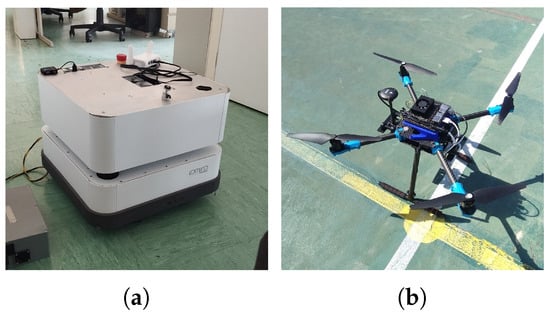
Figure 1.
Used ground and aerial vehicles. (a) UGV. (b) UAV.
2.3. UGV Localization
The proposed UGV localization scheme is illustrated in Figure 2. This implementation uses an EKF to fuse data from the IMU, wheel odometry, and LiDARs to estimate the robot’s state. The LiDAR measurements are processed using a Scan-to-Map Matching, S2MM, algorithm, which provides a position estimate in the map. Only a metric 2D floor plan with correctly scaled outer walls and shelf footprints is required. Fine details and transient obstacles are not needed. The current state estimated by the EKF is also used to initialize the minimization process of the S2MM algorithm. Once the matching is completed, the resulting LiDAR-based position estimate is fused with the other sensor inputs through the EKF to refine the overall state estimation. This modular design not only enhances adaptability to warehouse-specific challenges but also facilitates the integration of additional localization sources, such as relative information provided by the UAV.

Figure 2.
UGV localization algorithm scheme.
The state vector estimated by the EKF is presented in (1), where X and Y represent the robot’s position in the world’s fixed frame, and are the yaw and yaw’s angular rate, and and are the UGV’s linear speed and acceleration in the body frame.
The information extracted from the IMU will be the acceleration in the body’s x axis and the angular velocity of the yaw. The yaw measurement from the IMU was not considered as it is either an integration of or a compass reading, which would not be reliable in a warehouse due to the high amount of metallic structures. Since the differential drive configuration only allows translational movement in the body’s x direction and rotation around the z axis, the EKF will fuse the wheel odometry’s and readings. Finally, the S2MM process will provide measurements about the X, Y and states.
The IMU and wheel odometry sensors work at high frequencies and do not show much delay, but the same cannot be said for the S2MM output, since it requires more time for the scans processing, which can introduce significant delay in the arrival of the measurements to the EKF. Because of this, the S2MM measurements will be handled as delayed measurements by the filter. The deduction and details about this process are described in [23].
Scan to Map Matching Algorithm
The S2MM implementation draws inspiration from HectorSLAM [24] in the sense that it uses the approach of minimizing an error function that is directly related to the match between laser scan points and the map, although several modifications are proposed.
The goal of this minimization is to find the 2D position of the robot in the global frame: . Each laser scan in the body frame, , can be transformed to the global frame based on the estimated robot’s position, , by (2). A scheme of the used frames is present in Figure 3, where .
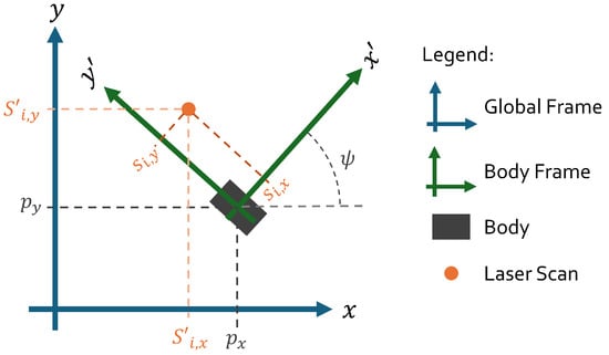
Figure 3.
Frames scheme.
Consider the function, calculated by (3), where and represent the closest obstacle to x and y in the map. The suggested error function to be minimized is given by (4), since the goal is to obtain the minimum distance between each laser scan and their closest occupied point. Figure 4 illustrates this concept: the analyzed laser scan, located at in the global frame, is matched with its nearest obstacle from the map, also expressed in the same frame. These quantities are then used in (3) to compute , whose result contributes directly to the error term in (4).
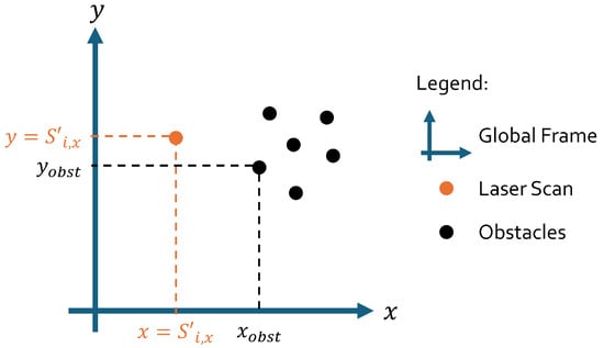
Figure 4.
Laser scan and obstacle relation scheme.
At each iteration, j, of the minimization process, the new estimated is calculated by and, by first order Taylor expansion and application of the Gauss–Newton gradient, can be calculated by (5), with given by (6).
A common problem of using gradient descent to minimize an error function is the chance of getting stuck on local minima. Additionally, in a warehouse environment, the number of local and global minima of the error function is amplified by the symmetric nature of the environment. To counteract this issue, a localized scattering of a small number of particles around the initial estimate is proposed. The S2MM algorithm is then applied for each of these particles. In particular, for this work, a pragmatic approach was adopted: nine particles were placed around the initial estimate by applying fixed, empirically chosen offsets, in meters, to x and y: , , , , , , , , and . These offsets were selected based on simulation experience to provide sufficient spatial coverage while maintaining computational efficiency. Orientation variation was not included among the particles, as it is typically well-corrected during the scan matching process due to the dominant linear features in the environment.
The final estimated position is based on the solution with the lowest error although some additional aspects must be considered. Firstly, if multiple particles converge to distinct position estimates that yield similarly low matching errors, the algorithm selects the estimation that lied closer to the initial EKF estimate. Alternatively, if the difference between the S2MM result and the initial EKF estimate exceeds three times the estimated standard deviation of the EKF’s positional uncertainty, the S2MM result is discarded. This outlier rejection is based on the 3-sigma rule associated with Gaussian distributions.
Finally, since the position obtained from the S2MM algorithm is used as a sensor measurement in the EKF, it requires an associated measurement noise matrix, . This work takes advantage of the error metric produced at each matching step, which gives an accurate indication of how much the EKF should trust the S2MM result at time k. After testing a few variations of how to calculate this error, the final formulation that gave the most consistent and realistic covariance estimate is presented in (7). The second term in (7) ensures that the covariance never becomes zero by setting a minimum default value. In this implementation, that value corresponds to twice the map resolution for and , and a fixed standard deviation for . Finally, to avoid penalizing scans with higher laser scan measurements, the error for each variable is averaged, and the orientation uncertainty is approximated using the overall matching error .
Note that the S2MM covariance is computed from the residuals of accepted matches and does not directly depend on the rejection ratio. As a practical enhancement, this covariance could be scaled by the number of valid matches or the update skipped when too many points are rejected.
The challenge of using a floor plan as a map must also be addressed. A floor plan usually does not include many of the smaller static obstacles present in the environment. Additionally, dynamic objects such as people or other vehicles can be detected by the LiDAR sensors but have no real correspondence in the map. These obstacles are referred to as outliers throughout this paper. Without any alteration, the S2MM algorithm will still try to match these outliers, which can lead to inaccurate position estimates. Therefore, relative motion threshold [25], RMT, is implemented to discard them. This algorithm works by rejecting all laser map matches whose distance, , is above the threshold defined in (8). The initial parameters and will influence the amount of discarded laser points, with high values leading to a small rejection percentage.
To improve robustness during scan matching, it is essential to define a threshold that accounts for the expected uncertainty in the estimated robot pose. This work suggests using , where and are the state covariance entries for the error variance of the state variables X and Y that are provided by the EKF. This 3-sigma bound is multiplied by 2 to account for the estimate error of the estimate and other errors. As for the value , which acts as the minimum value that a laser scan can have, an empirical value of four times the map resolution was used, and it accounts for discretization effects, quantization noise in the map and inaccuracies in the laser scanner or sensor model.
2.4. UAV Localization
To obtain the UAV’s relative position, the UGV carries the pattern shown in Figure 5, which has varied ArUco marker’s sizes so that the UGV can be detected by the UAV’s downward-facing camera at different altitudes. This design was based on the work developed in [26]. Table 1 presents the position of each marker in the pattern frame and their lateral sizes. All ArUco markers have the same orientation as the pattern and the marker with the highest ID will be the biggest marker in the pattern.
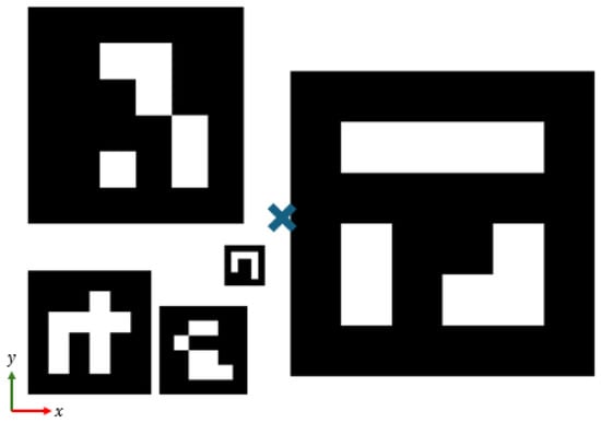
Figure 5.
Fiducial pattern used on the UGV. The symbol “X” marks the origin point of the pattern.

Table 1.
ArUco marker’s position and sizes in the pattern frame.
Since the relative position measured by different patterns can differ, at each instant if more than one marker is detected, the final UAV’s position estimate is given by (9), where represents the pattern frame, is the UAV’s stabilized frame, m is the number of detected markers, and is the area of marker i and . This process was thoroughly described in [26].
The global UAV position is obtained by computing its absolute pose from the relative pose to the UGV and the UGV’s global position. These vision-based measurements are then sent to ArduPilot, where they are fused with IMU data using its internal EKF.
Note that image capture occurs only during short, controlled flight phases and proved reliable under both indoor warehouse and natural outdoor lighting. For low-light environments, simple active illumination can be used—for example, UGV-mounted lights aimed at the pad/markers or a self-illuminated landing pad.
2.5. UAV-UGV Coordination and Trajectory Planning
A flow chart of the actions for the UAV-UGV collaboration during the warehouse inventory mission is shown in Figure 6. In this process, based on the available floor plan, the system extracts the entry points of each corridor, allowing an operator to define which corridors should be visited, i.e., which shelved should have their stock counted. For the purposes of this work, it is assumed that, if the robotic system is at the center of the corridor, it can count the stock from the two surrounding shelves. Upon receiving target corridors, the UGV transports the UAV to the nearest corridor’s entry point, where the UAV takes off, ascending at low speed to scan the inventory and transitions into follow mode once the target altitude has been reached. After the UGV travels a desired distance along the corridor and is stopped, the UAV performs a precise landing on the UGV, scanning a new area of shelves. This process is repeated until all the desired corridors have been visited. The length of each segment traveled by the UGV within the corridor should be defined according to the UAV’s field of view, so that all inventory items within that shelving section are fully covered during the UAV’s ascent and descent stages. Note that the operator actions are limited to pre-mission corridor/rack selection and safety supervision; all navigation, take-off/follow/landing, and image capture run autonomously.
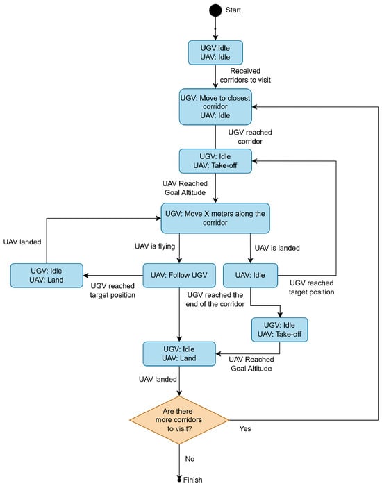
Figure 6.
High-level coordination flow chart illustrating UAV and UGV actions during inventory tasks.
The UGV’s control and local path planning is managed by an elastic band planner that guides the robot to the waypoints given by the high-level coordination module. The UAV’s flight stages use different control strategies: take-off and following are managed via ArduPilot’s Guided mode using ROS-set goals, while the landing relies on a custom PI velocity controller for precise alignment and image capture.
For the warehouse inventory mission, this PI controller was split into three separate stages, to first fix the state, then the x and y state and, finally, descend and land. The goal of this design is for the UAV to correct its x, y and before starting the descent so that, during this last stage, there is only significant movement in the z direction, at a constant rate, to obtain stable shelves images.
Consider that, at time , the UAV enters the precision landing mode with an initial relative pose and a target position , where is a predefined safety altitude that allows the UAV to still see the markers and perform any final corrections before completely landing. The desired velocity for each state is generated using a trapezoidal velocity profile defined by (10), with the time variables being defined in (11) and .
During each stage, the velocity command for each relevant state, i, is computed by combining the trapezoidal desired velocity and a PI controller, as computed by (12), where is the error between the estimated and desired positions.
Non-active states have their desired velocity set to zero but remain corrected via the PI controller until all the stages are completed. Once all states are within their respective error thresholds and desired velocities are zero, the UAV switches to ArduPilot’s land mode to complete the landing.
3. Simulation Results
To evaluate the system before deploying it in the real-world, a realistic simulation setup was developed using Gazebo.
3.1. Simulation Setup
A generalized warehouse environment was assembled using common warehouse objects provided by AWS RoboMaker Small Warehouse World [27] and is shown in Figure 7, along with the used floor plan map.
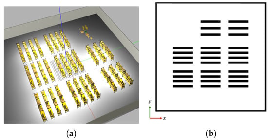
Figure 7.
Warehouse world used in simulation. (a) Warehouse in Gazebo. (b) Warehouse floor plan.
Because the warehouse stock varies through time, the shelves will have different item amounts and the geometry perceived by the LiDAR sensors will vary accordingly. These scans will be matched to the 2D floor plan in which shelves are represented as basic rectangular shapes, leading to a mismatch between observed LiDAR data and the reference map. To test the system under these stock variations, three maps of the same warehouse were constructed: one with empty bottom shelves, one with partially filled shelves, and one with fully stocked bottom shelves. Static objects not present in the map were also added to evaluate robustness under real-world inconsistencies.
Additionally, to test the robustness of the system, the IMU and wheel odometry sensors were simulated to have high noise and slip ratios: the IMU was simulated to have Gaussian noise with a standard deviation of 0.17 m/s2 and rad/s for the accelerometer and gyroscope, respectively. As for the wheel odometry, a white Gaussian noise with standard deviation equal to m was added to the wheel encoder’s output and a slip ratio of was simulated for both the linear and angular velocities.
3.2. UGV Localization
To evaluate the proposed UGV localization module under realistic conditions, simulations were conducted across the three distinct warehouse scenarios mentioned above. For all scenarios, four different paths were defined and simulated ten times. The paths were defined by sending specific sets of goal points, which are illustrated in Figure 8, as well as the ground truth UGV paths during the experiments. In all simulations, the proposed localization method was used by the path planner to control the robot. The goal positions were successfully reached in all but four cases, which were caused by synchronization issues between the controller’s finished state message and the reception of a new goal.
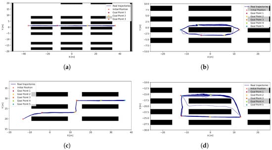
Figure 8.
Goal points and ground truth UGV trajectories for each simulated path. (a) Path 1. (b) Path 2. (c) Path 3. (d) Path 4.
The proposed UGV localization approach was compared to other common localization solutions, such as AMCL [28], KartoSLAM [29] and GMapping [30]. Figure 9 presents the boxplots of the absolute translational and rotational RMSE for each performed path.

Figure 9.
RMSE comparison of different localization algorithms across simulated paths. (a) Translational RMSE. (b) Orientation RMSE.
In terms of translational accuracy, AMCL generally exhibits the highest average RMSE. GMapping’s and KartoSLAM’s average RMSE are generally low and are overall comparable to the proposed method in terms of accuracy. However, the proposed approach stands out for its consistency: its RMSE remains low and tightly distributed across all scenarios, indicating it is less sensitive to environmental changes, leading to a more predictable performance.
For orientation errors, the proposed approach achieves the lowest average RMSE among all methods. GMapping and KartoSLAM show higher rotational errors, with worst-case RMSE values just under , which can accumulate into substantial drift over longer trajectories.
Considering both translational and rotational performance, the proposed localization strategy demonstrates high reliability and accuracy. It outperforms AMCL in both error magnitude and consistency, while offering a computationally efficient alternative to full SLAM systems, achieving comparable accuracy with lower complexity.
3.3. UAV Landing
In this section, the feasibility of the UAV’s landing controller is tested. For this, five simulations were performed, where the UAV took off to an altitude of 8 m, the UGV was dislocated in a random direction and orientation while the UAV stayed in place, and then the landing command was sent. The gains and maximum velocities used are presented in Table 2.

Table 2.
PI gains and maximum velocity and acceleration for UAV landing.
Figure 10 illustrates the UAV’s relative position to the UGV during landing. In simulation 5, the control stage is skipped due to the already aligned orientation. In other simulations, oscillations in x and y occur during the yaw correction, as these states are not actively controlled at that stage. Once the is aligned, the x and y control phase begins, successfully guiding the UAV toward the goal despite some oscillations. During the final descent stage, all states (x, y, and ) are maintained within acceptable bounds by the PI controller, and the UAV descends at a steady rate, meeting the requirements for precise warehouse inventory landings.
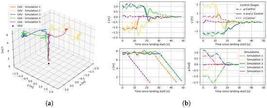
Figure 10.
UAV’s real states and trajectory in UGV’s frame during the landing simulations. (a) 3D trajectories. (b) States evolution.
3.4. UAV-UGV Collaboration
To test the feasibility of the assembled system and its autonomy and collaboration during the warehouse inventory operation, two different missions were simulated. Each mission began with a predefined initial position and a set of corridors to be visited, as illustrated in Figure 11. For the purposes of this demonstration, the predefined distance for the UGV to travel, denoted by X in the flowchart shown in Figure 6, was one quarter of the corridor’s total length, resulting in two separate UAV take-offs and landings per corridor.
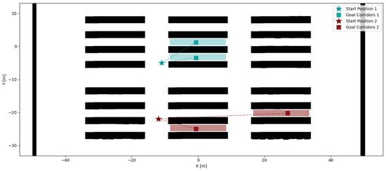
Figure 11.
Initial positions and target corridors for each simulated mission.
The real trajectories of the UAV and UGV during both missions are presented in Figure 12. This process is further represented in Figure 13, which shows a motion trail of the UAV and UGV’s position for the first visited corridor of mission 2.
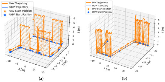
Figure 12.
Real trajectory of the UAV and UGV during the inventory missions. (a) Mission 1. (b) Mission 2.
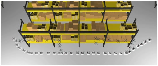
Figure 13.
Trajectory visualization of the UAV-UGV system during the first corridor crossing in Mission 2.
For both missions, the flowchart from Figure 6 was correctly followed: the UGV travels to the closest corridor’s entry, and the UAV takes off, follows the UGV and lands when intended, repeating the process until the corridor ends, at which point it travels to the next closest corridor entry and repeats the process.
Although the UAV’s motion shows some oscillatory behavior, it was still able to successfully achieve its intended goals, demonstrating the feasibility of the approach in simulation.
4. Real-World Experiments
To evaluate the proposed system modules under real-world conditions, a series of experiments were carried out with both the UGV and UAV in different environments, including an operational warehouse. For safety regulations, UAV tests could not be performed inside the warehouse at the moment and were instead conducted in an enclosed football field. Nevertheless, these trials enabled us to assess the feasibility of all developed modules and provided valuable insights into their robustness and applicability in realistic scenarios.
4.1. UGV Experiments
The objective of the UGV experiments were to analyse if the proposed localization solution allows for autonomous navigation under realistic sensor and environment uncertainties. The UGV was tested in two different environments: at IDMind’s office corridor and in a real warehouse.
Two types of tests were performed to evaluate the global localization solution:
- Test (1) Open-loop tests, in which the UGV was manually teleoperated using a joystick. These tests focused on evaluating the real-time performance and consistency of the localization system across varying trajectories and viewpoints.
- Test (2) Closed-loop tests, where the UGV was commanded to autonomously navigate to predefined goal points. These trials aimed to verify the effectiveness of the motion planning and control modules in achieving accurate and reliable navigation towards desired positions when using the proposed localization solution.
4.1.1. Experiments at IDMind
The experiments performed at IDMind were done in the corridor that is partially depicted in Figure 14a, with its map presented in Figure 14b.
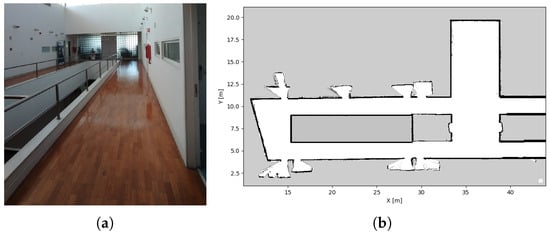
Figure 14.
IDMind’s corridor used for UGV’s experiments. (a) Testing space. (b) Map.
Before achieving the desired performance, several challenges had to be addressed during system deployment. Notably, the onboard IMU consistently experienced timeouts and automatic restarts, compromising the reliability of its measurements. As a result, IMU data was excluded from the localization pipeline, and state estimation relied solely on wheel odometry and LiDAR data. Additionally, the robot’s bumper was non-operational during testing. To allow the UGV to function despite this, and since the control and obstacle avoidance is not the main focus of these experiments, the safety checks dependent on the bumper status were temporarily disabled by bypassing the related code.
To perform Test 1, the UGV was manually guided along various trajectories covering the entirety of the available environment. The resulting position estimates, computed by the EKF using the proposed S2MM-based localization method, are depicted in Figure 15. As is common in real-world deployments, a precise initial position was not available. Instead, the EKF was initialized using a rough estimate, which reflects a realistic scenario, where exact initial localization is rarely guaranteed. With the proposed localization module, as long as the initial error was not excessive and sufficient structure was present in the environment to be detected by the LiDAR, the filter was able to quickly correct the initial uncertainty and provide consistent localization throughout the test.
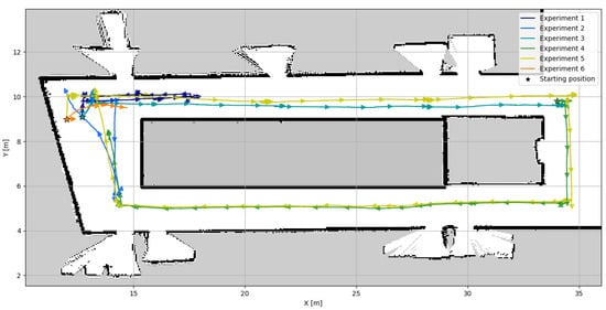
Figure 15.
EKF with S2MM position estimation for IDMind’s experiments.
Since there were no available methods to assess the vehicle’s ground truth position during the experiments, this work analyses the laser scans’ alignments to the map considering the estimated position. In addition, the results of the proposed solution, also denominated EKF with S2MM, are compared to the results of AMCL. The laser scan alignments obtained during experiment 5 are shown in Figure 16.

Figure 16.
Laser scan positions over time, transformed into the map frame using the UGV’s estimated pose. Experiment 5 from IDMind. (a) AMCL. (b) EKF with S2MM.
From this example, it is possible to conclude that both algorithms are able to maintain global localization without diverging but EKF with S2MM generally provides better scan matching. It is also evident that both approaches struggle with orientation estimation in some situations, which can stem from relying solely on wheel encoders for estimating the angular rate. Despite this, the proposed approach demonstrates a consistent and accurate localization performance, even in the presence of multiple static and dynamic obstacles, further reinforcing its robustness and feasibility. Additionally, it was noted that the proposed solution corrected the initial position estimate early, while AMCL only started to correct the position estimate when the robot started moving.
Additionally, KartoSLAM and GMapping were tested using the rosbag data from experiment 5. For these approaches, the quality of the obtained SLAM map was used as an indirect evaluation method, under the assumption that map quality reflects the consistency and accuracy of the underlying localization estimates. The maps generated by each SLAM approach are shown in Figure 17. GMapping initially produces a well-aligned map, but distortions emerge toward the end of the trajectory, suggesting drift in translational estimation. In contrast, KartoSLAM preserves the general wall positions but exhibits noticeable orientation drift, as indicated by diverging wall angles.

Figure 17.
IDMind’s corridor maps obtained through SLAM. (a) GMapping. (b) KartoSLAM.
For Test 2, two navigation experiments were conducted. Figure 18 illustrates the predefined goal points and the estimated trajectories obtained using the EKF with S2MM. In both experiments, the UGV successfully reached the designated goal positions based on its own localization estimates. Although external ground truth data was not available to precisely verify the robot’s final positions, successful arrival at the target areas was visually confirmed during testing. This is further supported by Figure 19, which presents snapshots of the UGV navigating toward goal 5 in Experiment 1.
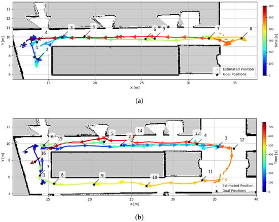
Figure 18.
EKF with S2MM position estimate and goal points from IDMind experiments. (a) Experiment 1. (b) Experiment 2.
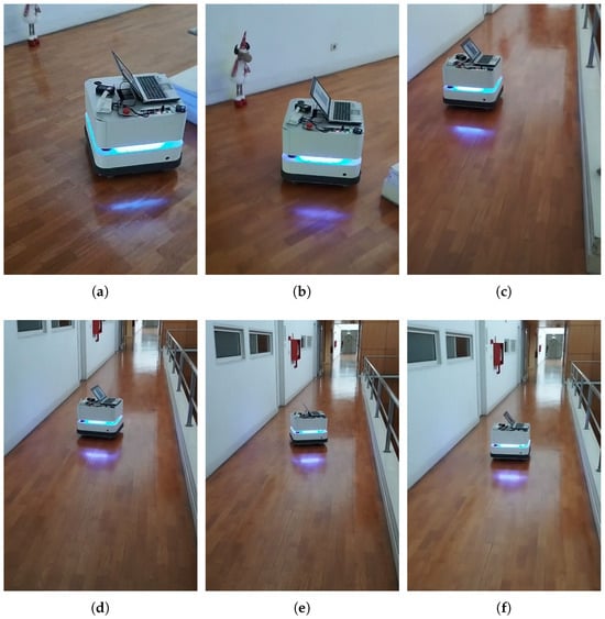
Figure 19.
Snapshots from UGV navigating to goal point 5 from Experiment 1 of Test 2 at IDMind. (a) Frame 1. (b) Frame 2. (c) Frame 3. (d) Frame 4. (e) Frame 5. (f) Frame 6.
4.1.2. Experiments at Warehouse
The warehouse tests were performed in the space depicted in Figure 20a. The floor plan of the space was transformed into the occupancy grid map shown in Figure 20b, which has a resolution of 5 cm. Since the tests were carried out during working hours, the available space to perform the tests was limited to the area depicted by the dashed line in Figure 20b, in order to not disturb the normal warehouse operations.

Figure 20.
Warehouse used for experiments. (a) Testing space. (b) Map.
The EKF with S2MM position estimates for both Test 1 and Test 2 are presented in Figure 21, where the initial position was again approximated based on the map. Although Test 2 was conducted as a single continuous run, Figure 21b divides the trajectory into two segments for a clearer analysis.
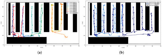
Figure 21.
EKF with S2MM position estimation for the warehouse experiments. (a) UGV commanded by joystick. (b) UGV commanded by goal points.
Considering once again the laser scans’ alignment to the map, it was concluded that, for experiments 1–7, the AMCL and EKF with S2MM results were similar and showed relatively good alignment of the laser scans to the map. One example of this can be seen in Figure 22, which shows the matching results for experiment 6.
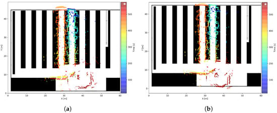
Figure 22.
Laser scan positions over time, transformed into the map frame using the UGV’s estimated pose. Experiment 6 from warehouse. (a) AMCL. (b) EKF with S2MM.
Still, experiments 1 through 7 represented short paths and durations. On the contrary, experiment 8 lasted approximately 45 min and covered the entirety of the available space in one continuous run. The laser scans’ matching to the map for this experiment is shown in Figure 23. For AMCL, it is possible to see that, around , the localization diverged and was not recovered at any point afterwards. As for the proposed method, it was able to provide stable position results during the entire experiment with good matching accuracy, although some occasional rotational and translational misalignment still occurred. The same thing happens with AMCL before its filter’s divergence. Rotational offsets were short-lived and arose because the IMU was disabled; yaw relied on wheel odometry and scan-to-map matching, which can settle in a nearby minimum in symmetric aisles. Restoring IMU fusion and strengthening scan-to-map matching will mitigate these effects.
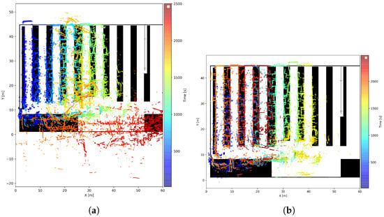
Figure 23.
Laser scan positions over time, transformed into the map frame using the UGV’s estimated pose. Experiment 8 from warehouse. (a) AMCL. (b) EKF with S2MM.
The trajectory planning of the UGV was also being tested in experiment 8. This experiment can be divided into two parts to obtain a better understanding of the results. In the first part, the UGV navigated through the entire available space using goal points that were set at a small distance from the current position, as can be seen in Figure 24a. The robot was able to navigate through the space and achieve the desired positions without any issue, except from goal 21 to goal 22, where it bumped into a box that was not depicted in the map. This issue would have been avoided if the safety checks had been active; however, since the focus of these experiments was the overall autonomous navigation capability, these issues were not addressed.

Figure 24.
EKF with S2MM position estimate and goal points from warehouse experiments. (a) Part 1. (b) Part 2.
The second part of this test aimed to evaluate the robot’s ability to autonomously navigate through corridors. For this purpose, the UGV was manually driven to the end of a corridor and then given a waypoint set at the end of a neighboring corridor and the obtained trajectory is seen in Figure 24b. Specifically, it received goal 1 while at the Start_1 position shown in the map, and later received goal 2 from the Start_2 position. Figure 25 shows the snapshots of the UGV navigating from the Start_1 position to goal 1. In the snapshots, the operator can be seen walking behind the UGV with a joystick, prepared to override the robot’s commands in case of failure. However, no manual intervention was required during the experiment.
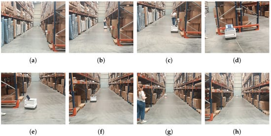
Figure 25.
Snapshots from UGV navigating to goal point 1 from Part 2 of Test 2 at Warehouse. (a) Frame 1. (b) Frame 2. (c) Frame 3. (d) Frame 4. (e) Frame 5. (f) Frame 6. (g) Frame 7. (h) Frame 8.
In all cases, the robot was able to navigate successfully between the corridors and reach the desired locations. It is worth noting that the paths generated by the elastic band planner caused the UGV to travel very close to the shelves. This behavior was not observed before since the previously sent goal points generally produced straight-line trajectories. Although acceptable for experimental validation, such behavior would not be suitable in a real warehouse scenario. This issue can be easily mitigated by either tuning the parameters of the planner or adopting an alternative global planning approach more appropriate for narrow or cluttered environments.
Based on the tests performed both in the warehouse and at IDMind, the proposed approach has demonstrated reliability and robustness under real-world conditions, especially when compared to alternative solutions, such as AMCL, GMapping and KartoSLAM. The results show that the method can serve as a valid and accurate alternative for localization, particularly in symmetrical environments where the traditional methods often struggle.
4.2. UAV Experiments
For the UAV’s experiments, the follow and landing modes were tested. The tests were performed at IST’s futsal field and used a general ground robot with a landing pad attached that carried the fiducial marker’s pattern. Because the tests were performed outdoors, the UAV was configured with two separate EKF instances in ArduPilot: one using GPS data only, and the other relying solely on the visual marker-based localization. Initially, the GPS-based EKF was active to support take-off and initial positioning. Once the UAV was airborne and stable, a controlled switch to the marker-based EKF was performed. This setup allowed the system to emulate indoor warehouse conditions, where GPS is unavailable, while still retaining GPS as a safety fallback in case of marker tracking loss or unexpected behavior.
Still, in these tests, the UAV performed autonomously without direct communication with the UGV; therefore, the pattern’s real position in the global fixed frame was not available to the UAV. It is also important to mention that the altitude estimation relied solely on the barometer to assure that, if the markers were lost, the UAV would keep receiving altitude measurements and avoid abrupt or unsafe altitude changes. Finally, the yaw estimation was also based only on the onboard compass rather than on the orientation derived from the marker-based localization. This choice was motivated by the fact that, if the markers’ pattern rotated, the ArUco-based localization could misinterpret the UAV’s heading and global position. By combining the UAV’s known heading with the relative pose from the marker, a more stable and accurate yaw estimate was achieved.
4.2.1. Follow Mode
Two follow experiments were performed using a manually piloted ground robot which carried the fiducial pattern. Figure 26 and Figure 27 show the estimated UGV and UAV positions in a local frame for those two experiments. The UGV’s position estimate is based on the GPS that was carried on board of the ground robot while the UAV estimation is based on the relative ArUco-based localization.
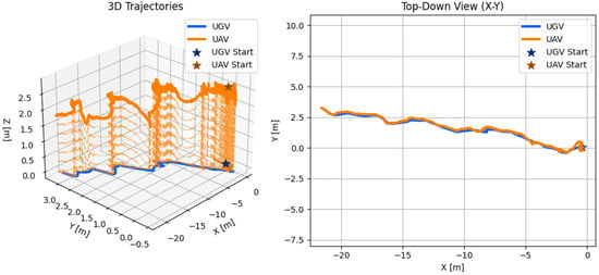
Figure 26.
UAV trajectory from ArUco-based localization and UGV trajectory from GPS measurements during follow mode. Experiment 1.
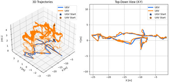
Figure 27.
UAV trajectory from ArUco-based localization and UGV trajectory from GPS measurements during follow mode. Experiment 2.
In the first experiment, the UGV was simply commanded to move in a straight line across IST’s futsal field. In the second, it followed a straight path initially, and then switched to a more free-form trajectory. In both cases, the UAV was able to follow the ground robot successfully, even under the constraining condition of not having a global position measurement available to estimate the UAV’s position. In Figure 28, sequential frames from the UAV’s camera during mission 1 are shown. These help to visualize how the UGV stayed approximately centered during the entire experiment, further showing the following capabilities of the proposed system.
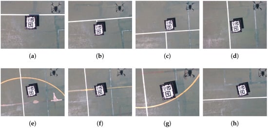
Figure 28.
Snapshots from the UAV’s onboard camera during follow mode’s mission 1. (a) Frame 1. (b) Frame 2. (c) Frame 3. (d) Frame 4. (e) Frame 5. (f) Frame 6. (g) Frame 7. (h) Frame 8.
4.2.2. Landing Mode
A total of four experiments were conducted to validate the system’s landing performance. The UAV’s position relative to the UGV, as estimated by the ArUco-based localization, is shown in Figure 29a, while Figure 29b illustrates the UAV’s x, y, z, and evolution over time in the same reference frame. For the first three experiments, the allowed position error before initiating landing was set to 20 cm, which was later reduced to 5 cm. In Experiment 3, the 20 cm threshold allowed the UAV to land slightly off-center, requiring pilot intervention, hence, the final altitude shown in Figure 29b does not reach zero. It should also be noted that the yaw was not controlled during these tests.
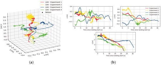
Figure 29.
UAV states from ArUco-based localization during landing mode in the four performed tests. (a) 3D trajectories. (b) States evolution.
Overall, the UAV was able to follow the landing sequence and land on the pattern within the set expected accuracy. While the controller performed reliably, some overshoot and oscillatory behavior are evident in the x and y position estimates, indicating potential areas for refinement in the PID tuning parameters. These dynamics, however, are understandable given the presence of environmental disturbances such as wind gusts, which add complexity to maintaining stable tracking and precise control.
Additionally, in Figure 30, sequential frames from the UAV’s camera during experiment 4 are presented, where it is possible to visualize the success of the landing mode.
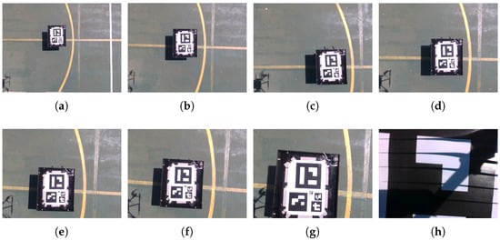
Figure 30.
Snapshots from the UAV’s onboard camera during experiment 4 of the landing mode. (a) Frame 1. (b) Frame 2. (c) Frame 3. (d) Frame 4. (e) Frame 5. (f) Frame 6. (g) Frame 7. (h) Frame 8.
Despite the given challenges, the system demonstrated robust performance and resilience, confirming the viability of the proposed approach for enabling autonomous precision landing in GPS-denied environments like warehouses. The results underscore the effectiveness of integrating visual marker-based localization with adaptive control strategies, paving the way for further optimization and deployment in real-world logistics and inventory management scenarios.
5. Conclusions
The goal of this paper was to contribute to the development and testing of an autonomous aerial–ground robotic system, composed of a UAV and a UGV, designed for stock taking and cycle counting tasks in warehouse environments. The main challenges of such a system regarding its autonomy fall in navigation in indoor, highly symmetrical, GPS-denied localization. Additionally, the challenges regarding the trajectory planning, high-level coordination and motion control of both robots were also addressed, in order to further advance on the contributions for the autonomous system.
The system’s implementation was thoroughly simulated and tested, with the simulation demonstrating the feasibility of the complete system in a realistic warehouse environment and the experimental tests further verifying some key components of the proposed solution. Particularly, the global localization algorithm showed consistent and reliable results, allowing the UGV to autonomously navigate in a real warehouse through a set of waypoints, outperforming AMCL, GMapping and KartoSLAM. As for the UAV, it was able to follow the UGV effectively throughout the tests. Moreover, the precision landing behavior was demonstrated successfully, with the UAV consistently landing within the targeted marker area with the desired accuracy. Therefore, the proposed solution demonstrated its feasibility and effectiveness in the simulated environments, and the experimental results attest to the viability of individual components of the system, laying a strong foundation for future integration and deployment.
As future work, the focus is on improving UAV safety and robustness with fail-safe strategies and additional sensing. ArduPilot tuning will be refined for smoother flight behavior. Full-system integration in real warehouse environments will be enabled. Obstacle detection from the UAV field of view will be integrated together with basic avoidance. A map-free local mode will be added that uses scan-to-scan odometry with wheel and IMU, re-localises to the floor plan when strong features reappear, and optionally refines shelf footprints online to handle incomplete or outdated plans. Finally, a marker-free, vision-based mobile target tracking approach is being investigated, building on previous work [31], to remove reliance on ArUco codes and support more flexible UAV–UGV cooperation.
Author Contributions
Conceptualization, R.C., P.A. and M.B.; methodology, R.C., P.A. and M.B.; software, R.C.; validation, R.C., P.A. and M.B.; formal analysis, R.C. and M.B.; investigation, R.C. and M.B.; resources, R.C., P.A. and M.B.; data curation, R.C. and M.B.; writing—original draft preparation, R.C.; writing—review and editing, R.C. and M.B.; visualization, R.C. and M.B.; supervision, M.B. and P.A.; project administration, M.B. and P.A.; funding acquisition, M.B. and P.A. All authors have read and agreed to the published version of the manuscript.
Funding
This research was partially supported by LARSyS FCT funding (DOI: 10.54499/LA/P/0083/2020, 10.54499/UIDP/50009/2020, and 10.54499/UIDB/50009/2020).
Data Availability Statement
The original contributions from this study are available in the article and on the GitHub repository: https://github.com/RafaelaChaffilla/aerial_ground_robotic_system_for_warehouse_inventory, accessed on 1 November 2025.
Conflicts of Interest
Author Paulo Alvito was employed by the company IDMind-Engenharia de Sistemas. The remaining authors declare that the research was conducted in the absence of any commercial or financial relationships that could be construed as a potential conflict of interest.
References
- Kembro, J.; Norrman, A. The transformation from manual to smart warehousing: An exploratory study with Swedish retailers. Int. J. Logist. Manag. 2022, 33, 107–135. [Google Scholar] [CrossRef]
- Gago, R.M.; Pereira, M.Y.A.; Pereira, G.A.S. An aerial robotic system for inventory of stockpile warehouses. Eng. Rep. 2021, 3, e12396. [Google Scholar] [CrossRef]
- Kalinov, I.; Safronov, E.; Agishev, R.; Kurenkov, M.; Tsetserukou, D. High-Precision UAV Localization System for Landing on a Mobile Collaborative Robot Based on an IR Marker Pattern Recognition. In Proceedings of the 2019 IEEE 89th Vehicular Technology Conference (VTC2019-Spring), Kuala Lumpur, Malaysia, 28 April–1 May 2019; pp. 1–6. [Google Scholar] [CrossRef]
- Harik, E.H.C.; Guérin, F.; Guinand, F.; Brethé, J.F.; Pelvillain, H. Towards An Autonomous Warehouse Inventory Scheme. In Proceedings of the 2016 IEEE Symposium Series on Computational Intelligence (SSCI), Athens, Greece, 6–9 December 2016; pp. 1–8. [Google Scholar] [CrossRef]
- Dhaliwal, A. The rise of automation and robotics in warehouse management. In Transforming Management Using Artificial Intelligence Techniques; CRC Press: Boca Raton, FL, USA, 2020; pp. 63–72. [Google Scholar]
- de Koster, R. Automated and Robotic Warehouses: Developments and Research Opportunities. Logist. Transp. 2018, 38, 33–40. [Google Scholar] [CrossRef]
- Custodio, L.; Machado, R. Flexible automated warehouse: A literature review and an innovative framework. Int. J. Adv. Manuf. Technol. 2020, 106, 533–558. [Google Scholar] [CrossRef]
- Inventory Drone—EYESEE. Available online: https://www.eyesee-drone.com/inventory-drone/ (accessed on 22 April 2025).
- Corvus Robotics—Warehouse Inventory Drones. Available online: https://www.corvus-robotics.com/ (accessed on 23 April 2025).
- Infinium Scan. Available online: https://infiniumrobotics.com/infinium-scan/ (accessed on 22 April 2025).
- Inventory with Drones—Doks.inventairy. Available online: https://doks-solution.com/doks-inventairy-drohne-inventur-lager-indoor/ (accessed on 22 April 2025).
- Dexory. Available online: https://www.dexory.com/ (accessed on 7 April 2025).
- DroneScan. Available online: https://www.dronescan.co/ (accessed on 23 April 2025).
- Guinand, F.; Guérin, F.; Petitprez, E. UAV-UGV Multi-robot System for Warehouse Inventory: Scheduling Issues. In Proceedings of the Computational Collective Intelligence, Rhodes, Greece, 29 September–1 October 2021; Nguyen, N.T., Iliadis, L., Maglogiannis, I., Trawiński, B., Eds.; Springer: Cham, Switzerland, 2021; pp. 241–254. [Google Scholar]
- Zhong, Y.; Wang, Z.; Yalamanchili, A.V.; Yadav, A.; Srivatsa, B.R.; Saripalli, S.; Bukkapatnam, S.T. Image-based flight control of unmanned aerial vehicles (UAVs) for material handling in custom manufacturing. J. Manuf. Syst. 2020, 56, 615–621. [Google Scholar] [CrossRef]
- Kwon, W.; Park, J.H.; Lee, M.; Her, J.; Kim, S.H.; Seo, J.W. Robust Autonomous Navigation of Unmanned Aerial Vehicles (UAVs) for Warehouses’ Inventory Application. IEEE Robot. Autom. Lett. 2020, 5, 243–249. [Google Scholar] [CrossRef]
- Qiu, Z.; Lin, D.; Lv, J.; Sun, Z.; Zheng, Z. A Closed Stockyard UAV Intelligent Inventory System. J. Phys. Conf. Ser. 2023, 2513, 012010. [Google Scholar] [CrossRef]
- Moura, A.; Antunes, J.; Dias, A.; Martins, A.; Almeida, J. Graph-SLAM Approach for Indoor UAV Localization in Warehouse Logistics Applications. In Proceedings of the 2021 IEEE International Conference on Autonomous Robot Systems and Competitions (ICARSC), Feira, Portugal, 28–29 April 2021; pp. 4–11. [Google Scholar] [CrossRef]
- Beul, M.; Droeschel, D.; Nieuwenhuisen, M.; Quenzel, J.; Houben, S.; Behnke, S. Fast Autonomous Flight in Warehouses for Inventory Applications. IEEE Robot. Autom. Lett. 2018, 3, 3121–3128. [Google Scholar] [CrossRef]
- Lewis, J.; Lima, P.U.; Basiri, M. Collaborative 3D Scene Reconstruction in Large Outdoor Environments Using a Fleet of Mobile Ground Robots. Sensors 2023, 23, 375. [Google Scholar] [CrossRef]
- Kalinov, I.; Petrovsky, A.; Ilin, V.; Pristanskiy, E.; Kurenkov, M.; Ramzhaev, V.; Idrisov, I.; Tsetserukou, D. WareVision: CNN Barcode Detection-Based UAV Trajectory Optimization for Autonomous Warehouse Stocktaking. IEEE Robot. Autom. Lett. 2020, 5, 6647–6653. [Google Scholar] [CrossRef]
- IDMind. IDMind—Living Robotics. Available online: https://www.idmind.pt/ (accessed on 3 May 2025).
- Carpenter, J.R.; D’Souza, C.N. Navigation Filter Best Practices; Technical Report; NASA, Langley Research Center: Hampton, VA, USA, 2018.
- Kohlbrecher, S.; von Stryk, O.; Meyer, J.; Klingauf, U. A flexible and scalable SLAM system with full 3D motion estimation. In Proceedings of the 2011 IEEE International Symposium on Safety, Security, and Rescue Robotics, Kyoto, Japan, 1–5 November 2011; pp. 155–160. [Google Scholar] [CrossRef]
- Pomerleau, F.; Colas, F.; Ferland, F.; Michaud, F. Relative Motion Threshold for Rejection in ICP Registration. In Field and Service Robotics; Howard, A., Iagnemma, K., Kelly, A., Eds.; Springer: Berlin/Heidelberg, Germany, 2009; Volume 62, pp. 229–238. [Google Scholar] [CrossRef]
- Morales, J.; Castelo, I.; Serra, R.; Lima, P.U.; Basiri, M. Vision-Based Autonomous Following of a Moving Platform and Landing for an Unmanned Aerial Vehicle. Sensors 2023, 23, 829. [Google Scholar] [CrossRef] [PubMed]
- AWS Robotics. AWS RoboMaker Small Warehouse World—GitHub Repository. Available online: https://github.com/aws-robotics/aws-robomaker-small-warehouse-world (accessed on 4 May 2025).
- Thrun, S.; Fox, D.; Burgard, W.; Dellaert, F. Robust Monte Carlo localization for mobile robots. Artif. Intell. 2001, 128, 99–141. [Google Scholar] [CrossRef]
- Konolige, K.; Grisetti, G.; Kümmerle, R.; Burgard, W.; Limketkai, B.; Vincent, R. Efficient Sparse Pose Adjustment for 2D mapping. In Proceedings of the 2010 IEEE/RSJ International Conference on Intelligent Robots and Systems, Taipei, Taiwan, 18–22 October 2010; pp. 22–29. [Google Scholar] [CrossRef]
- Grisetti, G.; Stachniss, C.; Burgard, W. Improved Techniques for Grid Mapping With Rao-Blackwellized Particle Filters. IEEE Trans. Robot. 2007, 23, 34–46. [Google Scholar] [CrossRef]
- Ferreira, D.; Basiri, M. Dynamic Target Tracking and Following with UAVs Using Multi-Target Information: Leveraging YOLOv8 and MOT Algorithms. Drones 2024, 8, 488. [Google Scholar] [CrossRef]
Disclaimer/Publisher’s Note: The statements, opinions and data contained in all publications are solely those of the individual author(s) and contributor(s) and not of MDPI and/or the editor(s). MDPI and/or the editor(s) disclaim responsibility for any injury to people or property resulting from any ideas, methods, instructions or products referred to in the content. |
© 2025 by the authors. Licensee MDPI, Basel, Switzerland. This article is an open access article distributed under the terms and conditions of the Creative Commons Attribution (CC BY) license (https://creativecommons.org/licenses/by/4.0/).