Abstract
Brake induced heating has become more difficult to control as bicycle component mass has been reduced. High-power braking with insufficient cooling or thermal capacitance can create excessive temperatures, boiling brake fluid, performance degradation, and damage. To better understand component heating, a disc braking dynamometer has been constructed with a motor driven disc, hydraulic braking, and a miniature wind tunnel. Disc temperatures are studied for various braking scenarios using infrared techniques and thermocouples. A transient, numerical, MATLAB, lumped parameter thermal/mechanical model is created to predict the impact of key design parameters on braking performance and to understand the heat loss mechanisms from the brake system components. Computational fluid dynamics (CFD) simulations are used to estimate the disc surface convective cooling coefficients for the model. The final model provides transient temperature predictions based on bicycle velocity and braking power, and successfully matches dynamometer experimental data.
1. Introduction
Improving the performance of bicycle braking and safety requires an understanding of the relationships between braking power and thermal dynamics, including the heating of components and braking power dissipation to the surrounding freestream. A transient model of component heating is useful to understand the thermal dynamics and component temperatures. The automotive industry has long ago accepted the benefits of brake thermal modeling and testing [1], and there have been recent efforts to test bicycle brakes on a test bench [2], and to measure brake power during outdoor trials [3]. The focus in this work is to develop a bicycle disc brake thermal model and to provide experimental validation of its predictive capability in a laboratory environment.
2. Materials and Methods
2.1. Experimental Dynamometer
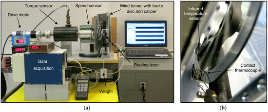
The disc braking dynamometer shown in Figure 1 has been constructed with a geared electrical motor which turns a bicycle disc through a torque sensor. A hydraulic brake caliper and pad assembly provides braking torque, and a miniature wind tunnel provides airflow over the disc and caliper assembly to represent bicycle speed V (m/s). The airflow’s convective cooling is crucial to properly approximate real bicycle riding and to realistically distribute the heat escape to various components. Rotational speed is measured via a 72-tooth slotted optical wheel speed sensor. The brake disc is made of 420 series stainless steel and measures 1.8 mm in thickness, with a 160 mm outer diameter and a 130 mm inner disc diameter for the braking surface. The disc has twelve radial spokes which connect the braking surface to the hub attachment area.

Figure 1.
Brake dynamometer experimental setup: (a) Overall setup and data collection equipment; (b) Photograph looking into the wind tunnel inlet with disc in motion, showing the temperature sensor locations.
Disc temperatures are measured by a sliding surface-contact, type K thermocouple, an Omega OS100E series infrared (IR) optical non-contact thermometer and a Mikron MikroScan 7515 IR camera with 320 × 240 pixel resolution. The contact thermocouple and IR thermometer provided continuous data, whereas the IR camera was used intermittently, since one of the wind tunnel walls needed to be removed to provide optical access to the disc.
Multiple data sets were obtained at 200 Hz via a computer data acquisition system for various freestream air speeds and braking input levels. Heating and cooling tests were performed where constant hydraulic braking pressure was generated by hanging a 0.5 kg mass on the vertical brake lever during testing. The disc rotational speed was set to be consistent with a 680 mm diameter bicycle wheel, with its center travelling at the chosen wind tunnel air velocity. Both the wind tunnel velocity and the disc rotational speed were maintained constant during the tests. Once the disc heated up, the braking force was released, thus allowing the disc to cool down. The focus of this work is on the thermal performance, although the dynamometer has proven the ability to generate several modes of brake induced vibration [4], yet another concern for bicycle brakes.
2.2. Numerical Model
A MATLAB, transient, numerical model was formulated where the disc braking surface mass was modeled as a lumped thermal capacitance with a heat input from the braking power, heat losses due to convection, conduction into the caliper/pad assembly, and conduction into the spokes (then cooled by convection). The transient energy model for the lumped thermal mass is:
where is the braking surface mass (kg), is the specific heat (460 J kg−1 K−1), T represents disc temperature and is time. The equation above is integrated numerically using finite difference time stepping in order to solve for the temperature change between time steps of 0.005 s. The net heat rate (W) is divided as follows:
Besides the braking power heat input , the brake disc model has six heat loss areas that are described in the sections below: the left surface, the right surface, the inner edge surface, the outer edge surface, the spokes connecting the disc to the hub, and the brake pad contact areas. A computational fluid dynamics model (CFD) was used to model the heat loss from the first four disc surfaces, a finite difference heat loss model was used to determine the spoke heat loss, and parameter tuning to experimental data provided values for the pad heat loss.
2.2.1. Braking Power ()
In the equation above (W) is the instantaneous braking power calculated from the experimentally measured torque (), and angular velocity ω (rad/s) given by ω.
2.2.2. Heat Rates (, , , )
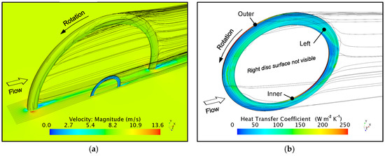
To model the heat loss from the left, right, outer and inner surfaces, a CFD model was set up in STAR-CCM+ where a disc (without spokes) was modeled adjacent to a bike wheel at freestream velocities of 4.47 m/s, 8.94 m/s, and 13.41 m/s (10, 20 and 30 MPH, respectively). The model included rigid body rotation of the disc and bike wheel, and a moving ground plane. (The dynamometer wind tunnel described above, however, only incorporated a rotating brake disc without a wheel or moving ground plane.) The disc surfaces were kept at a constant surface temperature relative to the freestream, and once converged, the CFD model provided surface convective coefficients for the four disc surfaces. Surface to freestream temperature differences of 50, 100, 150, and 200 K were used. In total 12 cases were run (10.14 million cells per case), each providing average heat transfer coefficients for the four disc surfaces mentioned above. Figure 2 shows representative results from one case showing the complex local flow field and surface convective values for the disc. Table 1 shows the corresponding total convective power transfer capability for the entire disc as a function of temperature difference and bike speed. Note that these values are strictly for the disc geometry shown in Figure 2b and exclude additional spoke and pad heat transfer. The decrease in convective coefficient with ∆T in the table is due to the thermal wake effects from the leading half of the brake disc that can be seen in Figure 2b.

Figure 2.
CFD heat transfer environment as viewed from the left side for a disc brake at 8.94 m/s (20 MPH), disc to ambient ∆T = 100 K, flow from left to right, and counterclockwise wheel and disc rotation showing: (a) Velocity field and streamlines; (b) Brake disc geometry with nearby streamlines and surface heat transfer coefficient contours for a constant disc surface temperature.

Table 1.
Disc convective cooling coefficients and cooling power for various and bike velocities. An 80 kg bicycle/rider descending an 8% grade at a steady 8.94 m/s requires a combined 559 W of energy dissipation from aerodynamic resistance, rolling resistance and wheel braking.
To provide an analytic convective heat transfer equation for the MATLAB code, each disc surface’s average heat transfer coefficient was curve fitted as a function of bike velocity and surface to freestream temperature difference . The fitting function used is:
where h is given as a function of (m/s) and . Table 2 shows the resulting fitting coefficients for each surface of the disc shown in Figure 2b. Comparing the left and right surfaces, the coefficient differences may seem large, but that is an artifact of the curve fits. In actuality for a given and the difference in actual power dissipation capability (W) between the left and right surfaces is always under 3.5%, and is due to the asymmetric disc location relative to the wheel center.

Table 2.
Curve fits for the average convective heat transfer coefficient of individual disc surfaces resulting from the CFD model, as a function of bike velocity (m/s) and temperature difference between the surface and freestream in degrees K.
A surface’s heat transfer rate (W) is related to the surface’s average convective coefficient h from Equation (3) by , where is the area. Additionally, there is a radiative loss term included in the model for each of the disc’s left, right, inner edge and outer edge surfaces, but the radiative term is negligible for the values here.
2.2.3. Heat Rate ()
A transient, multi-element, finite difference, numerical heat transfer method is used to model the heat loss from the variable cross-section of the disc spokes which connect the brake disc to the hub. The trapezoidal element shape was based on disc spoke measurements that start wide near the disc (14 mm), taper to a narrower waist at half length (5 mm), and then widen again near the hub (7 mm). The spoke thickness was 1.8 mm (disc thickness), while the spoke length was 40 mm. The governing transient heat equation for each element is similar to Equation (2) for the disc, except for the introduction of both convection and conduction terms in the heat rate term (where i denotes each element):
where is the convective surface area computed for the trapezoidal element, and is the spoke convection coefficient. The variable k is the thermal conductivity (24.9 W m−1 K−1), and denote the disc-side/hub-side cross section areas, and or denote the adjacent element temperatures. The model uses 40 nodes, with one node every 1 mm along the spoke length. The spoke tip was set to ambient temperature—an approximation to represent the heat transfer to the large thermal mass of the hub. The only tuning parameter in this model is the spoke convective coefficient which was determined experimentally during cooldown with no braking when .
2.2.4. Heat Rate ()
The heat loss through the pads is the least understood and most difficult parameter to model as the heat path from the pads to the air involves conduction through the pad backing plates, the hydraulic cylinders, the brake fluid, and the caliper housing. The pads tested here included fin arrangements as part of the pad backing plates, and hence for this work the disc heat loss term due to the brake pads ( was modeled as a convective heat loss term where the convective parameter was used to model the entirety of the heat loss through the pads, caliper, fluid, etc.; and was an empirically fitted parameter adjusted to minimize the disc temperature error between the experimental contact thermocouple and model transient tests. The area of the pads was set as the area corresponding to a 20° arc of the disc left and right surfaces.
3. Results
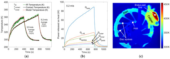
An experimental heat-up/cool-down test at a freestream speed of 4.0 m/s was used to tune the numerical model convective coefficients: and . The fitted value used in this work for the spokes is = 4.75 {W s m−3 K−1}·V, and the fitted value found for the pad heat transfer coefficient is = 25 {W s m−3 K−1}·V; where V is the freestream bike velocity in m/s. Figure 3a shows a comparison for two other heat-up/cool-down experiments for 3.5 m/s and 5.2 m/s velocities. The model parameters were not adjusted for these two experiments and are taken directly from the 4.0 m/s test, thus these results are indicative of the predictive capability of the model. Figure 3b shows the power release details for 5.2 m/s, while Figure 3c shows representative IR thermography results. The pad fins and caliper have an unknown emissivity and thus the IR temperatures in the figure for those surfaces are not accurate—the actual temperatures are likely lower.

Figure 3.
Numerical model and experimental results: (a) Comparison of model temperature prediction to experimental contact and IR non-contact thermometer temperatures for 3.5 and 5.2 m/s with total average errors between the model and contact temperatures indicated; (b) Model predicted heat release from each surface for 5.2 m/s; (c) Infrared thermography image during heating, with disc model temperature at 356 K and emissivity set to 0.19, i.e., the same emissivity applied to the IR non-contact thermometer data shown to the left.
4. Discussion
The 5.2 m/s simulation in Figure 3a shows excellent agreement with the experiment, whereas the 3.5 m/s simulation over predicts the transient heat-up rate, and under predicts the transient cooldown rate. In the future, fitting the and coefficients using multiple data sets may provide more holistic agreement, particularly as the velocity varies. An emissivity of 0.19 was found to successfully match the IR non-contact thermometer and IR camera temperatures to the contact thermocouple temperature. During the heating, brake pad clamping force, air velocity, and disc rotation rate were kept constant, but the dynamometer measured power dissipated by the brakes increased due to the larger friction associated with the increasing disc temperatures. For example, for the 5.2 m/s case the brake power increased from 37 W at the start of the test to 89 W at the peak temperatures. Figure 3b shows that initially the spokes absorb and expel most of the brake power, but then are surpassed by the combined left/right disc braking surfaces. Overall the model predicts that the cooling is primarily due to the disc surfaces (left/right, inner and outer), with the disc spokes being secondary contributors, and the pads/caliper being tertiary contributors, only 7.5% of the total when at peak temperature for the case shown. Although heating of the pad fins and caliper is clearly evident from IR image in Figure 3c, the proper measurement of pad fin and caliper temperatures via contact methods and IR thermography remains for future work. Future work will include modeling of peak temperatures from sustained “hill descents” at constant speed; this analysis is postponed here as a model is still needed for aerodynamic, rolling, and braking resistance fractions.
5. Conclusions
A transient, numerical, MATLAB thermal model based on the convective heat transfer coefficients obtained from CFD simulations has been successfully matched to the experimental temperatures measured on a brake dynamometer for a bicycle hydraulic disc brake. The authors provide and validate fitting functions for the convective coefficients for bicycle brake discs, for various bike speeds and disc to freestream temperature differences. The model successfully predicts the heating and cooling temperature curves for the dynamometer. Most of the cooling is attributed to convection from the disc left and right braking surfaces. Further work will include determination of friction coefficients, application of the model to bicycle braking data from actual outdoor courses, and additional infrared thermography comparison to component temperature measurements.
Acknowledgments
No external funding for research or publication has been received. The authors would like to acknowledge SRAM LLC for bicycle braking discussions and for loaning various brake components.
Conflicts of Interest
The authors declare no conflict of interest. The funding sponsors had no role in the design of the study; in the collection, analyses, or interpretation of data; in the writing of the manuscript, and in the decision to publish the results.
References
- Sheridan, D.; Kutchey, J.; Samie, F. Approaches to the Thermal Modeling of Disc Brakes; SAE Technical Paper 880256; SAE: Warrendale, PA, USA, 1988. [Google Scholar]
- Oertel, C.; Neuburger, H.; Sabo, A. Construction of a test bench for bicycle rim and disc brakes. Procedia Eng. 2010, 2, 2943–2948. [Google Scholar] [CrossRef][Green Version]
- Miller, M.C.; Fink, P.W.; Macdermid, P.W.; Perry, B.G.; Stannard, S.R. Validity of a device designed to measure braking power in bicycle disc brakes. Sports Biomech. 2017, 1–11. [Google Scholar] [CrossRef] [PubMed]
- Redfield, R. Bike braking vibration modelling and measurement. Procedia Eng. 2014, 72, 471–476. [Google Scholar] [CrossRef]
Publisher’s Note: MDPI stays neutral with regard to jurisdictional claims in published maps and institutional affiliations. |
© 2022 by the authors. Licensee MDPI, Basel, Switzerland. This article is an open access article distributed under the terms and conditions of the Creative Commons Attribution (CC BY) license (https://creativecommons.org/licenses/by/4.0/).