Abstract
This paper proposed a dead-time compensation method with fractional-order proportional integral (FOPI) error voltage control. The disturbance voltages caused by the power devices’ dead time and non-ideal switching characteristics are compensated for with the FOPI controller and fed to the reference voltage. In this paper, the actual error voltage is calculated based on the model and actual voltage of the permanent magnet synchronous motor. Considering the parameter error of the permanent magnet synchronous motor and the voltage error caused by the dead-time effect, a FOPI controller is used to calculate the compensation voltage. An improved particle swarm optimization (PSO) algorithm is utilized to design the parameters of the FOPI controller in order to eliminate the dead-time effect, and the optimal fitness function is designed. Compared with other optimization algorithms, the improved PSO algorithm can achieve faster convergence speed in the error voltage controller parameter design. The proposed dead-time compensation method can improve the performance of the current response and eliminate the dead-time effect. This method also eliminates all harmonic disturbances and has a good suppression effect on high-frequency harmonics. The simulation and experimental results show that the dead-time compensation method using optimal FOPI error voltage control makes the current ripple smaller and the response speed faster than that of the traditional optimal integer-order PI control, thus demonstrating the effectiveness and advantages of the proposed method.
1. Introduction
The pulse width modulation (PWM) voltage source inverter (VSI) has been extensively used in permanent magnet synchronous motor drive systems. The dead time should be inserted in switching signals to avoid any shoot-through in the inverter lags of the PWM-VSI system. Because of the dead time of the inverter, there is a voltage drop between the output voltage and the reference voltage. The voltage drop caused by the dead time brings serious problems, such as current distortion and torque pulsation. Especially when the current is nearly zero, the output voltage distortion is more severe. Hence, it is vital to reject the disturbance from the dead time and improve the performance of current trucking.
Practical approaches have been discussed to overcome this problem. These methods can be sorted into three categories: (1) methods based on the modification of the PWM signal; (2) methods based on current harmonics monitoring; (3) methods based on model observation.
In the methods based on the modification of the PWM signal, the pulse width error caused by dead time is compensated for by detecting the current polarity and adjusting the PWM pulse width. In [1], this voltage error is compensated during the next switching period by modification of a reference voltage, the proposed solution can be used to compensate for the voltage error in multilevel multiphase voltage source inverters, but [1] requires additional hardware, which increases the cost and complexity of the system. If the polarity information is not accurate enough, the performance will worsen after compensating. The modified PWM signals are obtained using an off-line calculation in [2], this method relies on the precise detection of current polarity. However, obtaining accurate current polarity at zero-crossing instants is difficult, so it is necessary to determine the current polarity with the help of a more complicated signal processing algorithm. In [3], polarity detection accuracy is improved by using feedback circuits to measure inverter output voltages and Kalman filters to reconstruct fundamental phase currents. These approaches require additional circuits, which increase the end-product cost and hardware complexity.
In the PWM VSI system, the dead-time effect produces sixth-order current harmonics in the synchronous reference frame. According to this theory, the methods based on current harmonic monitoring are proposed [4,5,6,7,8,9,10,11]. The scheme in [4,5,6,7,8,9,10,11] can directly reduce the dead-time current harmonics by generating compensation voltage references while the motor is operating under steady conditions. Although those methods can make the proposed scheme effective in both the steady and transient states, the algorithm converging speed could be improved by limiting computation efforts. In [12], those approaches to the motor design improved the sinusoidal degree of the back electromotive force (EMF) by optimizing the distribution of the stator windings and the structure of the stator slots. Although the approaches can attenuate the harmonics caused by the slot effect and the magnetic saturation, the harmonics generated with the nonlinear characteristics of the inverter still exist [12]. The method based on the proportional-resonant (PR) regulator was also presented. It can track the reference for the positive and negative sequence currents without errors simultaneously [13], although the methods are effective, the interference between the different frequencies needs to be eliminated, and the algorithms need to be simplified. In [4], a dead-time-related harmonic minimization method is proposed based on proportional-integral (PI) controller tuning and under the premise of keeping the same control strategy; however, this method cannot completely eliminate the dead-time effect, which still has a great impact on the control system. This method [4] is compared with the method proposed in this paper. The methods based on current harmonics monitoring cannot take into account the high-frequency harmonic disturbance caused by the dead-time effect; moreover, the algorithm implementation of this method is more complex and requires higher hardware processors.
The methods based on model observation use a disturbance observer to estimate error voltages [14,15,16], Furthermore, it not only reduces the sixth harmonic as in many other compensation methods but also deals with its multiples concurrently. In [15], this paper introduces a current harmonic elimination method based on a disturbance observer (DOB), Although the DOB was shown to be able to satisfactorily operate under a constant change in the rotational speed of the machine, this method has not been verified for the dynamic response performance during motor startup. In [17], the expression of the inverter input current was derived by considering the deadtime effect. However, these models are not suitable for closed-loop control systems such as VSI-fed field-oriented control (FOC) PMSM servo systems. The control scheme using two extended state observers (ESO) is proposed in [14], which provides a strong ability to suppress dead-time effects, but the effect of this method can be further improved. In the following, the method using ESO [14] is compared with the method proposed in this paper.
In recent years, the number of studies related to the application of fractional controllers has been increasing. Fractional order control achieves better performance than conventional integer-order control, which can provide an opportunity to adjust better the dynamical characteristics of the control system [18,19,20,21]. And fractional-order proportional integral (FOPI) control has been widely used for servo systems [20]. Therefore, the FOPI controller is applied in our proposed dead-time compensation method to pursue advanced robustness.
This paper proposes a dead-time compensation method for a PMSM servo system with an optimal FOPI error voltage control. The proposed method based on the model of PMSM can calculate the error between the reference and output voltages, and the FOPI controllers can make the error voltages of the d-axis and q-axis converge to zero quickly. The proposed control strategy uses the PSO algorithm to design the parameters of the FOPI controller, considering the nonlinearity of the dead-time effect. The proposed dead-time compensation strategy can reduce the current disturbance in the VSI system. A PMSM system is used to validate the proposed method. Simulation and experimental results are presented to demonstrate the effectiveness of the proposed method.
The main contributions of this paper are as follows. (1) This paper proposes a dead-time compensation method for PMSM servo systems with optimal FOPI error voltage control. The method proposed in this paper can not only eliminate low-frequency harmonic disturbances but also has a good suppression effect on high-frequency harmonics. A voltage model with dead-time effect and parameter error of permanent magnet synchronous motor is established. The actual error voltage is calculated based on the model and actual voltage of the permanent magnet synchronous motor. Considering the parameter error of the permanent magnet synchronous motor and the voltage error caused by the dead-time effect, the FOPI controller is used to calculate the compensation voltage. (2) An improved particle swarm optimization (PSO) algorithm is utilized to design the parameters of the FOPI controller, and in order to eliminate the dead-time effect, the optimal fitness function is designed. Compared with other optimization algorithms, the improved PSO algorithm can achieve a faster convergence speed in the error voltage controller parameter design. (3) Through theoretical and experimental analysis, it is proven that the method proposed in this paper can have good error voltage control performance and robustness in the case of motor parameter errors.
The rest of this article is organized as follows. The formula derivation process for the error voltage caused by the dead-time effect is presented in Section 2. In Section 3, a dead-time compensation method with optimal FOPI error voltage control is proposed, and the parameter tuning procedure of the FOPI controller is also presented. The simulation and experiments using the proposed dead-time compensation method are presented in Section 4 and Section 5, compared with the dead-time compensation method using optimal integer-order proportional integral (IOPI) control, the dead-time compensation method using ESO [14] and the dead-time-related harmonic minimization method [4]. Finally, the conclusion is given in Section 6.
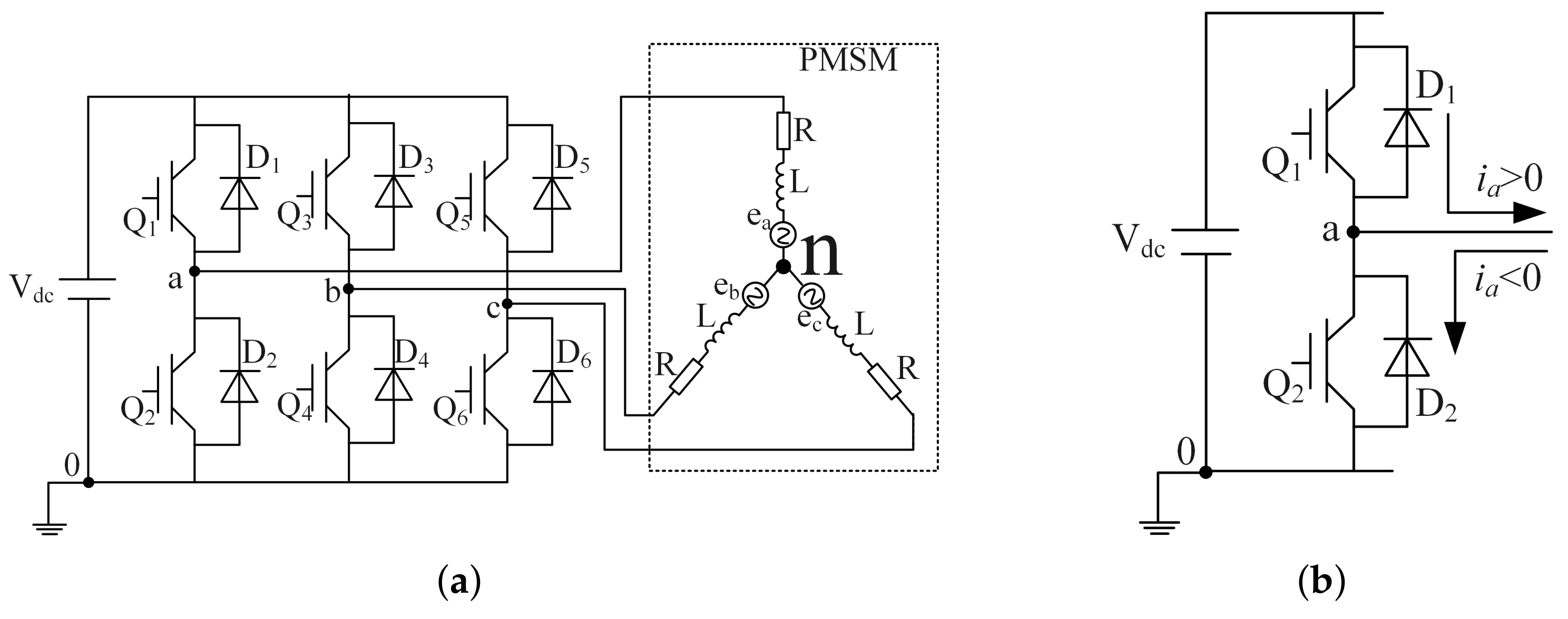
2. Analysis of Dead-Time Effect
The typical three-phase PWM inverter with PMSM load is illustrated in Figure 1.
Figure 1.
Model component. (a) Three-phase PWM drive system. (b) One phase leg of the PWM inverter.
In practice, a dead-time, , is inserted in the gating signals to guarantee the safety of the VSI system. The gating signals with the dead time added are shown in Figure 2b. During the dead-time period , the switches in Figure 1 are turned off, and the terminal voltage is determined by the direction of the a-phase current [22]. Figure 2c is the ideal terminal voltage. Considering the dead time and the turn ON/OFF delay, the terminal voltage is illustrated in Figure 2d,e. In this case, the a-phase average terminal voltage error over one PWM period can be given as
where is the a-phase average terminal voltage error over one PWM period, is the direction of the a-phase current, and represents the magnitude of the terminal voltage error, which is defined as
where is the dc-link voltage, is the dead time, is the PWM carrier period, is the turn-on time delay of the switching device, is the turn-off time delay of the switching device, and is the forward voltage drop of the switching device and of the diode.
Figure 2.
Switching pattern and terminal voltages: (a) Ideal gate signals. (b) Real gate signals with dead-time; (c) Ideal terminal voltage; (d) terminal voltage with dead-time and time delay when > 0; (e) Actual terminal voltage with dead-time and time delay when < 0.
In a similar way, the distorted voltage errors of other phases can be obtained. The error voltages in the three-phase stationary reference frame are obtained as
where , and are the three-phase terminal voltage errors of VSI and , , and are the phase voltage errors of the PMSM in the three-phase stationary reference frame.
The error voltages in the stationary frame can be transformed to the synchronous reference frame as
where and are the d-axis and q-axis error voltages of the PMSM in the synchronous reference frame caused by dead-time effect, is the Park’s transformation, and is Clark’s transformation, is the rotor electrical position.
The analysis mentioned above demonstrates that the dead-time error voltage can be influenced by current polarity, the turn ON/OFF delay, the voltage drop of the switching device, and the diode. It is inaccurate for detecting current polarity because of the clamping of current around the zero-crossing point. Due to the change in operating conditions, such as temperature, many parameters affecting dead-time compensation are difficult to measure. Thus, it takes work to compensate for the effect of dead time directly.
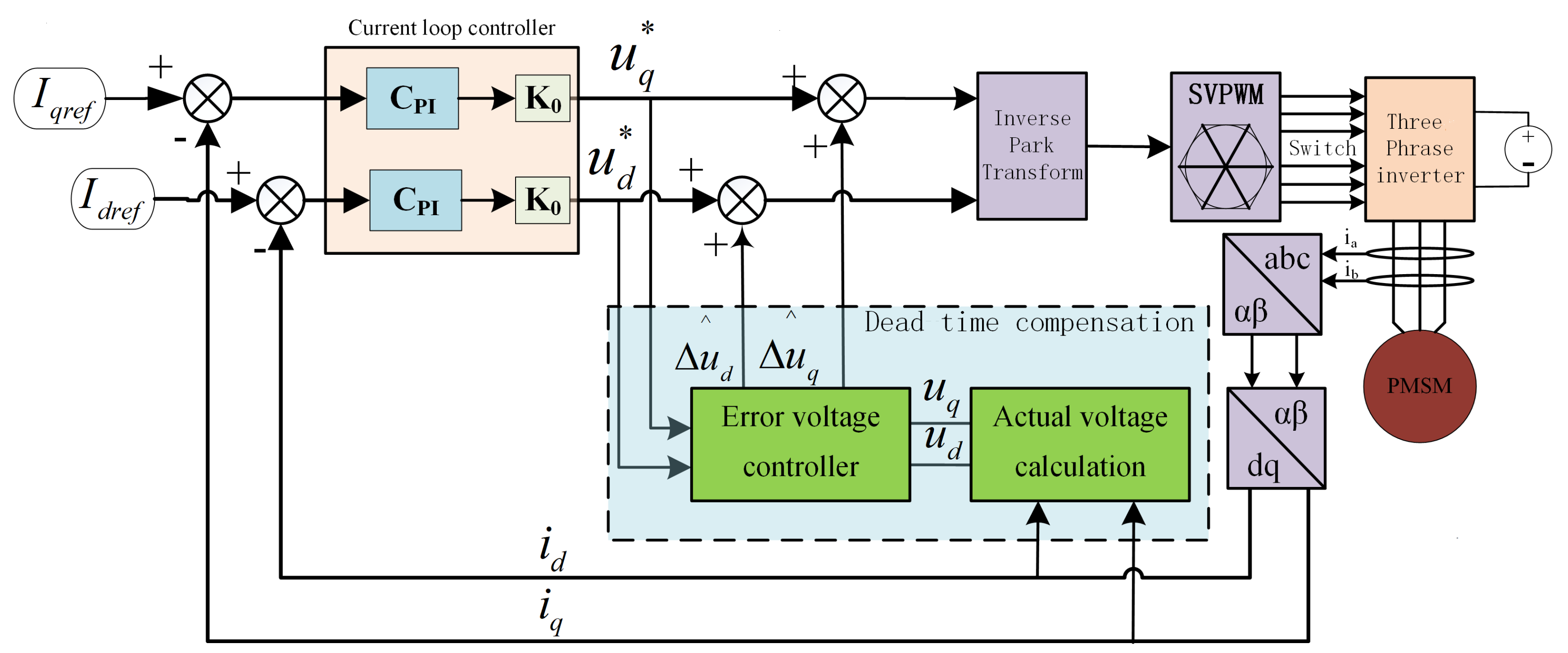
3. Proposed Dead-Time Compensation Strategy
3.1. Error Voltage Calculation Based on PMSM Model
The dynamic model of PMSM in the synchronous reference frame can be represented as (7).
where is the d-axis actual voltage, is the q-axis actual voltage, is the d-axis current, is the q-axis current, and , , , and represent the stator inductance, resistance, rotor electrical angular velocity, and rotor flux linkage.
Therefore, the dynamic model of PMSM in the discrete-time domain is represented as:
where k represents the kth PWM period, and are the d-axis current and q-axis current of the kth PWM period, and are the d-axis voltage and q-axis voltages of the PWM period, and is the sampling period.
Since proper motor parameters cannot be obtained in practice, the equivalent error voltage caused by the motor parameter error can be obtained through (9)
where and represent the nominal stator inductance, nominal resistance, and and represent the equivalent error voltage caused by the motor parameter error.
Affected by the dead-time effect of the inverter, there is an error between the reference voltage and the output voltage. According to (8), the dynamic model of PMSM, including the error voltage in the discrete-time domain, can be represented as:
where and represent the d-axis and q-axis reference voltage of the PWM period and and represent d-axis and q-axis error voltages caused by dead-time effect.
Based on (10), the total error voltage caused by the dead-time effect and motor parameter error in the synchronous reference frame can be calculated using (12).
where and represent the actual nominal voltages of the d-axis and q-axis calculated from the nominal motor parameters, and represent d-axis and q-axis error voltages.
Therefore, to control the error voltage caused by the dead-time effect and the uncertainty error voltage caused by motor parameter error, it is necessary to use a FOPI controller with high control performance.
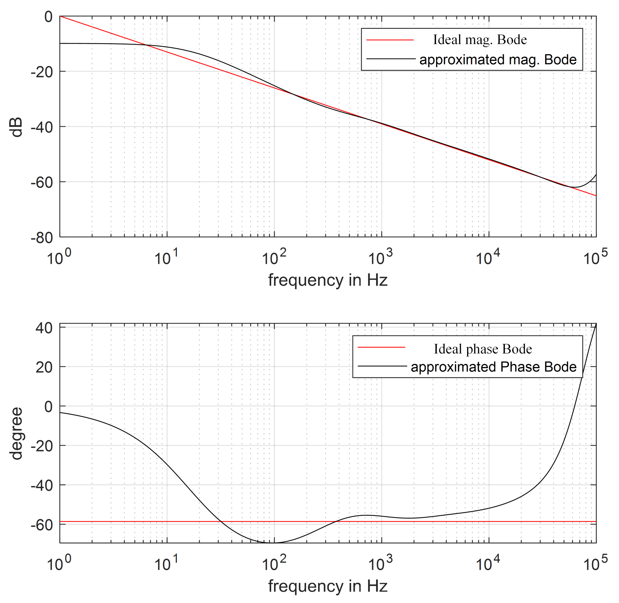
3.2. Compensation Method with Optimal FOPI Error Voltage Control
Figure 3 shows the system control block diagram. The actual voltage calculation module is shown in Figure 4, which can be represented by (12). When using the compensation method with optimal FOPI error voltage control, the system control block diagram is also shown in Figure 3. The compensation method with optimal FOPI error voltage control uses the FOPI controller as the error voltage controller. The control objective is to make the actual d-axis and q-axis voltages of the motor follow the reference voltages. The error voltage caused by the dead-time effect can be reduced as much as possible.
Figure 3.
Block diagram of the system control.
Figure 4.
The actual voltage calculation module.
is the transfer function of the FOPI controller, which is shown as (13).
where and are proportional and integral gains and is a fractional order. In this paper, we consider .
According to the impulse response invariance method [23], the higher the order, the higher the accuracy. However, a high approximation order results in more operating time for the microprocessor. Therefore, in practical applications, the approximation order is chosen based on control performance requirements and hardware constraints. The z-domain expression of the fractional operator can be obtained with
where and (i = 1…5) are the discretization coefficients of fractional-order operators.
When using the compensation method with optimal FOPI error voltage control, the error voltage controller is shown in Figure 5 and is the q-axis compensation voltage. The calculation is as in (17).
where and represent the proportional and fractional-order integral terms of the q-axis FOPI error voltage controller of the kth PWM period, as in (18) and (19).
Figure 5.
FOPI error voltage controller.
The is the d-axis compensation voltage. The calculation is as in (20).
where and represent the proportional and fractional-order integral terms of the d-axis FOPI error voltage controller of the kth PWM period, as in (21) and (22).
where and are the q-axis and d-axis compensation voltages of the kth PWM period, and are proportional and integral gains of d-axis FOPI error voltage controller, and and are proportional and integral gains of q-axis FOPI error voltage controller.
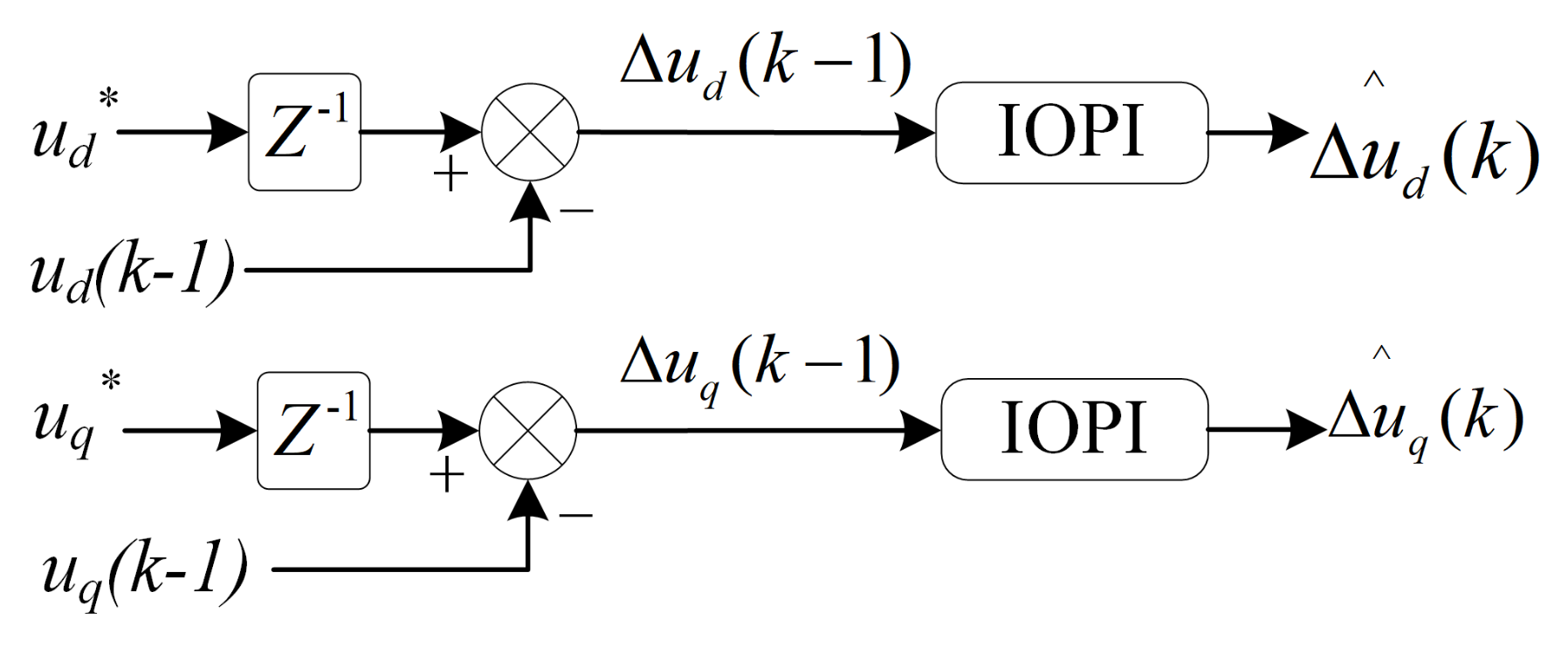
3.3. Compensation Method with Optimal IOPI Error Voltage Control
The FOPI controller can be superior to the IOPI in control performance and robustness. To prove the necessity and superiority of using the FOPI controller, the IOPI controller is used for error voltage control and compared with the FOPI controller. The compensation method with optimal integer order proportional integral (IOPI) error voltage control uses the IOPI controller as the error voltage controller.
is the transfer function of the IOPI controller, which is shown as in (23).
where and are proportional and integral gains.
When using the compensation method with optimal IOPI error voltage control, the error voltage controller is shown in Figure 6. The compensation voltages are the output of the IOPI controllers. The calculation is as in (24) and (25).
Figure 6.
IOPI error voltage controller.
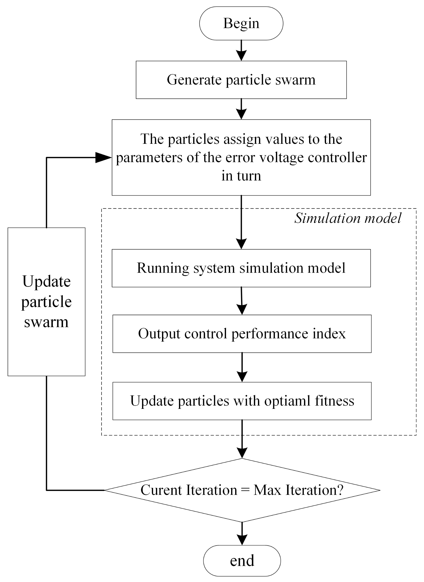
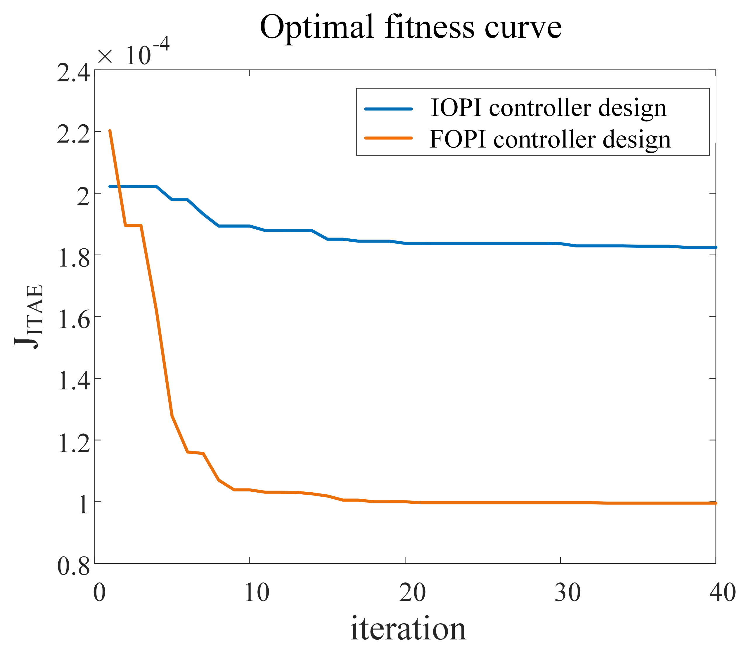
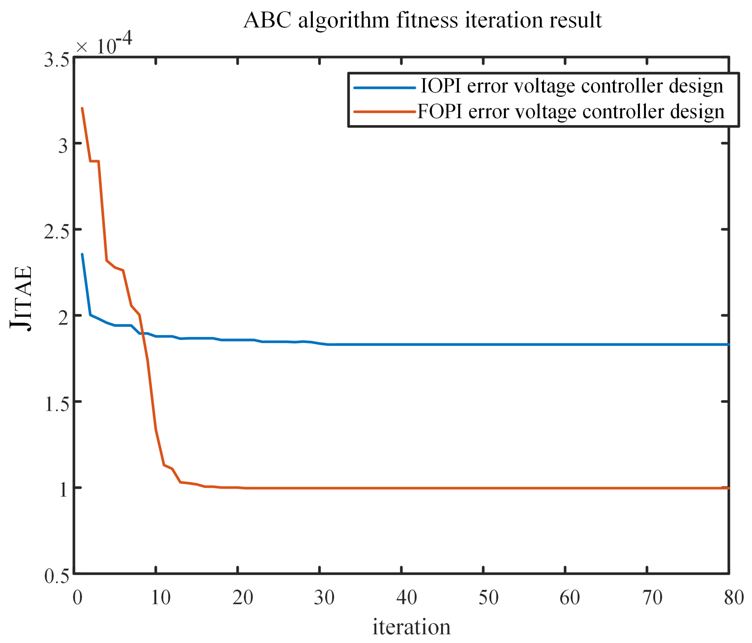
3.4. Parameter Design of Error Voltage Controller Based on Improved PSO Algorithm
Due to its simplicity and ease of implementation with only a few parameters, the particle swarm optimization (PSO) algorithm has shown desired optimization performance in continuous optimization problems, and discrete optimization problems [24,25,26]. Because of the non-linear characteristics of the dead-time effect, it is challenging to use frequency domain analysis to design the parameters of the error voltage controller. In this paper, the improved PSO algorithm is presented to develop the parameters of the error voltage controller, and the process is shown in Figure 7.
Figure 7.
The process of parameter design of error voltage controller.
In Figure 7, the position of the particle represents the parameters of the error voltage controller, and the fitness function represents the performance index of the compensation effect. When using the method with optimal IOPI error voltage control, the position of the particles corresponds to the parameters of the IOPI controllers. When using the method with optimal FOPI error voltage control, the position of the particles corresponds to the parameters of the FOPI controllers.
The following is the optimization procedure. First, a particle swarm is generated, and the positions of the particles are sequentially assigned to the parameters of the error voltage controller (IOPI controller or FOPI controller). Then the performance index corresponding to the set of parameters can be obtained by the simulation model of the control system. By evaluating the fitness function, the optimal fitness value and particle position can be obtained. Finally, it is judged whether the maximum number of iterations is reached. If not, the operation of updating the particle is performed. If the number of iterations equals the maximum number of iterations, the algorithm obtains the optimal position.
The update operation of particles mainly includes speed update and position update, which are calculated according to (26).
where is the particle’s position of the ith iteration, i is the number of iteration, is the particle’s velocity of the ith iteration, and are the position and velocity of the the iteration, and is the inertia weight at the ith iteration. and are the acceleration coefficients, and control the relative proportion of cognition and social interaction in the swarm. and are random numbers between [0,1], is the optimal position of a single particle until the ith iteration, and is the optimal position of the entire particle swarm until the ith iteration.
To dynamically adjust the inertia weight, we consider , and the inertia weight at the ith iteration is as in (27).
where and are constants, the is maximum number of iteration.
As in (28), the acceleration coefficient keeps decreasing over time, and the acceleration coefficient keeps increasing over time.
where , , , and are constants, which are the initial and final values of and , and the is the maximum number of iteration.
The purpose of the error voltage controller is to minimize the q-axis voltage error and the d-axis voltage error. The q-axis current ripple directly causes the torque ripple. It greatly influences the system’s control performance, so this paper pays more attention to the voltage error control effect of the q-axis. Referring to the evaluation index of ITAE, the fitness function is set to , as in (29).
where and represent the d-axis and q-axis error voltages of the kth PWM period. t is the running time of the system.
When using the compensation method with optimal IOPI error voltage control, the particle position is shown in (30).
where and are proportional and integral gains of the d-axis IOPI error voltage controller and and are proportional and integral gains of q-axis IOPI error voltage controller.
For designing the parameters of the IOPI controller, the configuration of the improved PSO algorithms is shown in Table 1.
Table 1.
The configuration of the improved PSO algorithm.
Based on the configuration in Table 1, the parameters of the IOPI controller are optimized by the PSO algorithm. The convergence curve of the optimal fitness function value with the number of iterations is shown in Figure 8.
Figure 8.
PSO algorithm Optimal fitness function value in FOPI/IOPI controller design.
The parameter iteration result of the IOPI controller based on the improved PSO algorithm is shown in Table 2.
Table 2.
The parameter iteration result.
When using the compensation method with optimal FOPI error voltage control, the particle position is shown in (31)
where and are proportional and integral gains of the d-axis FOPI error voltage controller, and are proportional and integral gains of q-axis FOPI error voltage controller, is the fractional order of the d-axis FOPI error voltage controller, and is fractional order of q-axis FOPI error voltage controller
For designing the parameters of the FOPI controller, the configuration of the improved PSO algorithms is shown in Table 1.
Based on the configuration in Table 1, the parameters of the FOPI controller are optimized using the PSO algorithm. The convergence curve of the optimal fitness function value with the number of iterations is shown in Figure 8.
The parameter iteration result of the FOPI controller is shown in Table 2.
The Artificial Bee Colony (ABC) Algorithm is an optimization algorithm based on intelligent behavior.
For the parameter design of the IOPI/FOPI controller, the parameter optimization curve of the ABC algorithm is shown in Figure 9 [27]. The comparison of the iterative optimization results of the ABC algorithm and the PSO algorithm is shown in Table 3, it can be seen that the optimal fitness values obtained by the two algorithms are approximately equal, which proves that the controller parameters obtained in Table 2 are the global optimal solution. Compared with the ABC algorithms, the improved PSO algorithm can achieve a faster convergence speed in the error voltage controller parameter design.
Figure 9.
ABC algorithm Optimal fitness function value in FOPI/IOPI controller design.
Table 3.
Comparison of optimal fitness function Values between ABC algorithm and PSO algorithm.
The is the fractional order of the d-axis FOPI error voltage controller. According to Table 2, = 0.651. The discrete implementation of can be obtained using the impulse response invariance method [23], and the comparison of discretization approximate bode graph and ideal bode graph is shown in Figure 10. The is the fractional order of the q-axis FOPI error voltage controller, and the comparison of discretization approximate bode graph and ideal bode graph of is shown in Figure 11.
Figure 10.
The comparison of discretization approximate bode graph and ideal bode graph of .
Figure 11.
The comparison of discretization approximate bode graph and ideal bode graph of .
3.5. Parameters Design of Current Loop Controller and Speed Loop Controller
The PMSM current can be controlled with two PI controllers. Without dead-time compensation, the simplified PMSM current control system is shown in Figure 12.
Figure 12.
The simplified PMSM current control system.
The current loop controller model is as in (32)
where and are proportional and integral coefficients. The open-loop transfer function of the current loop is as follows:
where and are constants. represents the voltage conversion coefficient, and represents the current conversion coefficient. and represent the stator inductance and resistance,
According to the existing system, = 179.561 and = 1/19.2. The current controller is designed by the cancellation method with relationship / = L/R [28]. The gain crossover frequency is set as = 2000 rad/s,
4. Simulation Results
The proposed method is compared with the method without compensation to demonstrate the effectiveness of the dead-time compensation method with optimal FOPI error voltage control. The proposed method is compared with the method using optimal IOPI error voltage control and the compensation with extended state observers (ESO) [14] to indicate higher performance using optimal FOPI control. In order to prove that the FOPI error voltage control method has a good ability to eliminate current harmonics, this dead-time-related harmonic minimization method [4] is compared with the proposed method. The simulation model is built using MATLAB/Simulink, which has the same control scheme and parameters as the drive system. The dead time in the gate of power switches is 2.1 s. The simulation control block diagram is shown in Figure 3, the is set to 1 A, and the is set to 0 A. According to (35) and (36), The parameters of the current loop controller can be calculated as = 1.4018 and = 121.8973. The parameters of the error voltage controller are shown in Table 2. Other specifications of the simulation drive system are given in Table 4.
Table 4.
Specification of experimental drive system.
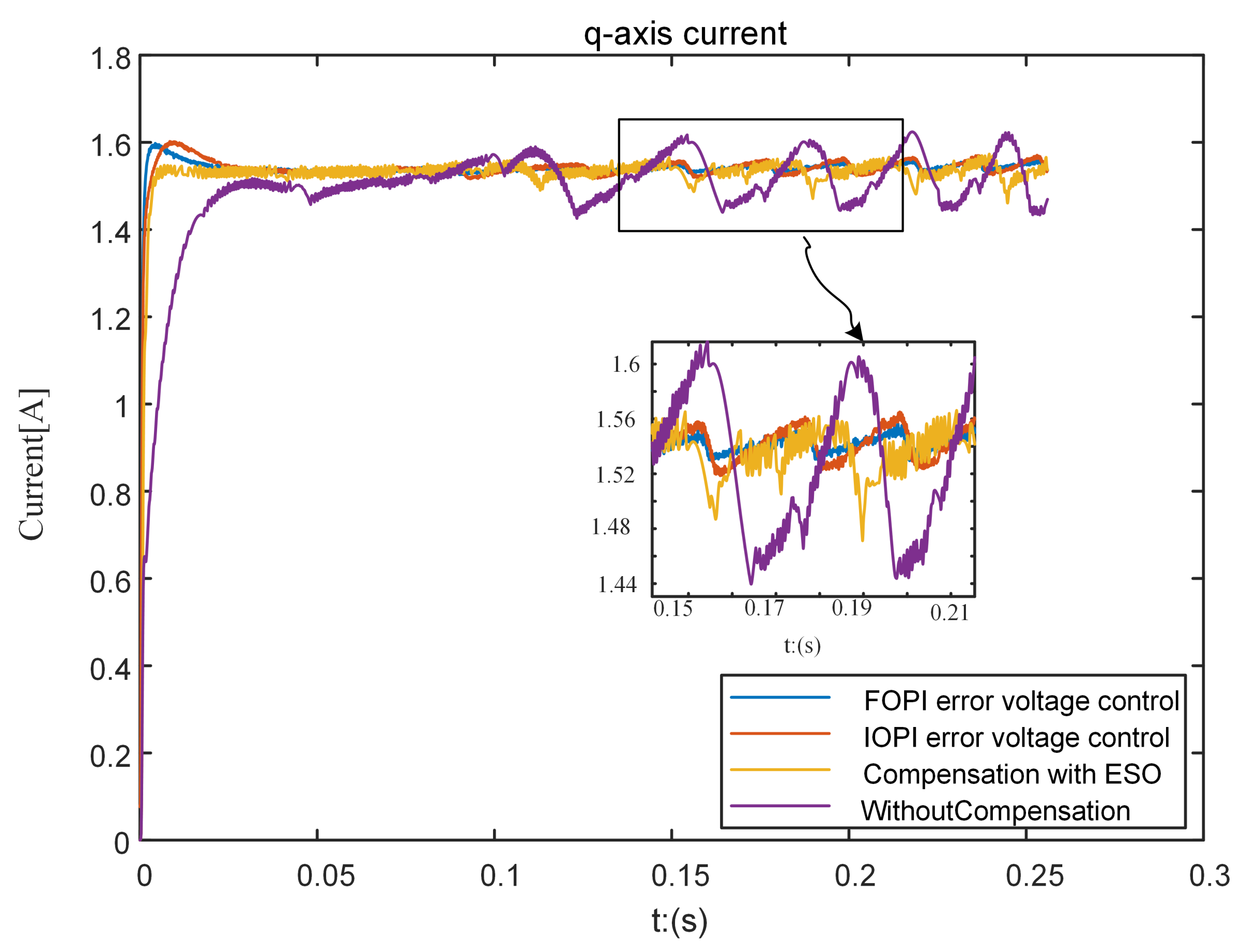
4.1. Current Closed-Loop Simulation
The simulation result of current is shown in Figure 13 and Table 5. As we can see, the current of the method without compensation is much distorted because of the dead-time effect, and the torque ripple in the steady state is very severe. When using the dead-time compensation method with optimal FOPI error voltage control, the current ripple can be significantly eliminated, and the tracking performance can be improved. Compared with the IOPI error voltage control and the compensation with ESO [14], it can be seen that the method with optimal FOPI error voltage control can further improve tracking performance and reduce the current ripple of the current. Compared with the compensation with ESO [14], the optimal FOPI error voltage control can effectively suppress high-frequency harmonic disturbance.
Figure 13.
The comparison of step current response of three control strategies.
Table 5.
The performance index comparison of step current response in the simulation.
In the simulation, the comparison of the current response under the three control strategies is shown in Figure 14 and Table 6. The dead-time compensation method with optimal FOPI error voltage control can significantly reduce the current disturbance caused by the dead-time effect, and the method with optimal FOPI error voltage control has a more vital ability to suppress the disturbance of the current than that using optimal IOPI error voltage control and the compensation method with ESO [14]. Figure 15 and Table 7 show the three-phase current response comparison results. The dead-time compensation method with optimal FOPI error voltage control can significantly eliminate the current distortion and reduce the current clamping around the zero-crossing point. The method’s performance with optimal FOPI error voltage control is better than that of IOPI error voltage control, which proves that the proposed method has a better dead-time compensation effect. Compared with the compensation with ESO [14], the optimal FOPI error voltage control can effectively suppress high-frequency harmonic disturbance.
Figure 14.
Comparison of current response of three control strategies.
Table 6.
The performance index comparison of step current response.
Figure 15.
Comparison of three-phase current response of three control strategies.
Table 7.
The performance index comparison of three-phrase current step current response.
The q-axis error voltage simulation results are shown in Figure 16. The q-axis error voltage varies nonlinearly with increasing speed when using the method without compensation. The dead-time compensation method with optimal FOPI error voltage control can quickly make the error voltage converge to 0. The convergence speed of the proposed method is faster than that of the method using optimal IOPI error voltage control. The method with optimal FOPI error voltage control makes the q-axis error voltage converge to 0 faster than the method with optimal IOPI error voltage control.
Figure 16.
Comparison of the error voltage of q-axis.
The d-axis voltage error simulation results are shown in Figure 17. It can be seen that the d-axis error voltage fluctuates significantly under the influence of the dead-time effect, and the dead-time compensation method with optimal FOPI error voltage control can substantially reduce the d-axis error voltage.
Figure 17.
Comparison of the error voltage of d-axis in the simulation.
4.2. Speed Closed-Loop Simulation
In the case of keeping the motor speed constant at 200 r/min, compare the method proposed in this paper with the typical current harmonic elimination method. Observe and compare the three-phase current and its frequency spectrum. In [4], a dead-time-related harmonic minimization method based on proportional-integral (PI) controller tuning is proposed under the premise of keeping the same control strategy. In order to prove that the FOPI error voltage control method has a good ability to eliminate current harmonics, this dead-time-related harmonic minimization method [4] is compared with the proposed method.
The three-phase current simulation results and their spectral analysis for the dead-time-related harmonic minimization method and the method [4] proposed in this paper are shown in Figure 18 and Figure 19. It can be seen from Figure 18 that the proposed method can more effectively eliminate the current clamping phenomenon caused by the dead-time effect. At the point where the current passes through 0, the current clamping time of the proposed method is shorter than the dead-time-related harmonic minimization method [4]. It can be seen from Figure 19 that the proposed method is better than the dead-time-related harmonic minimization method [4] in eliminating the dead-time effect harmonics.
Figure 18.
Comparison of three phase current response under 200 r/min speed conditions.
Figure 19.
Frequency domain simulation analysis of A phase current under 200 r/min speed conditions.
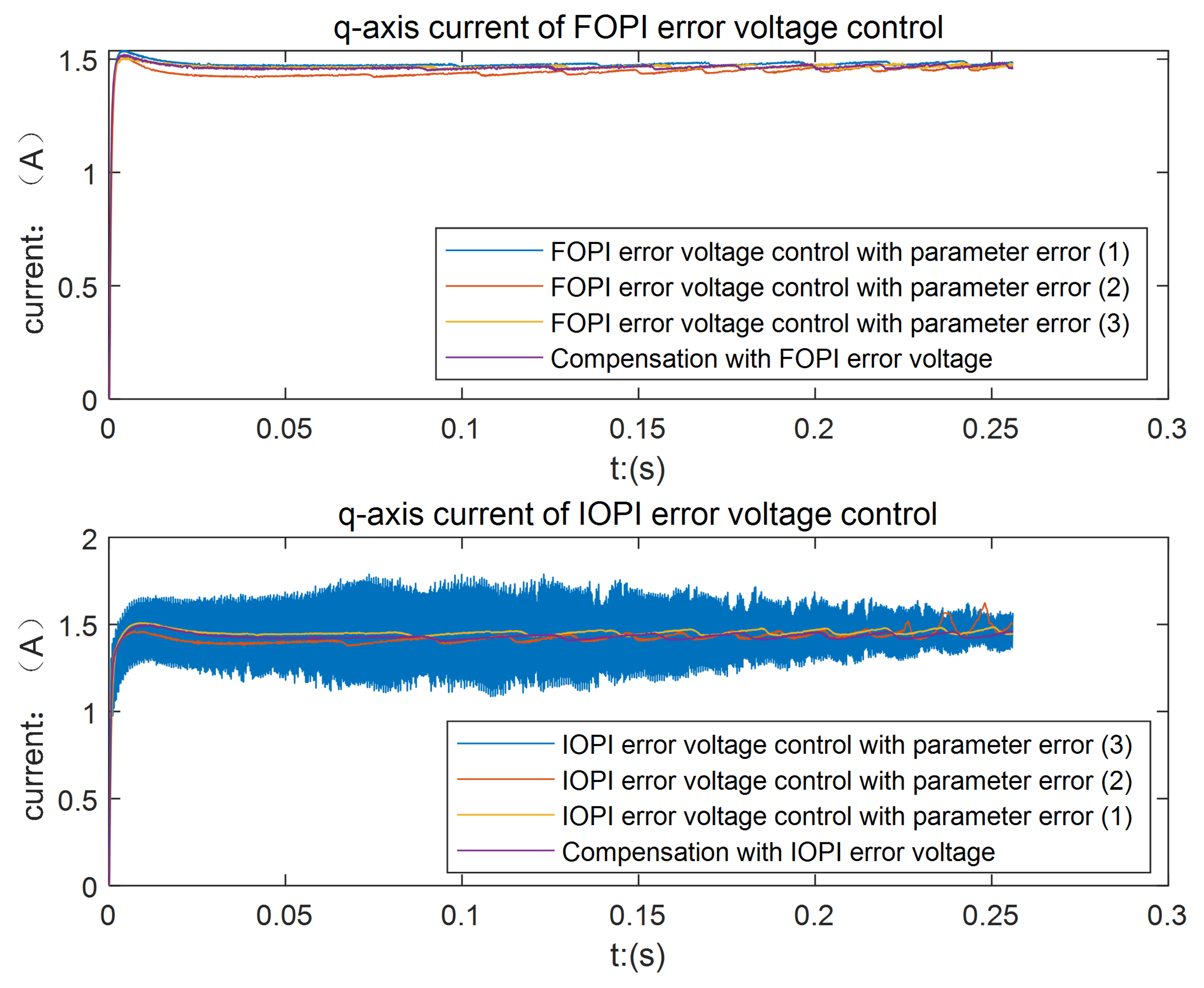
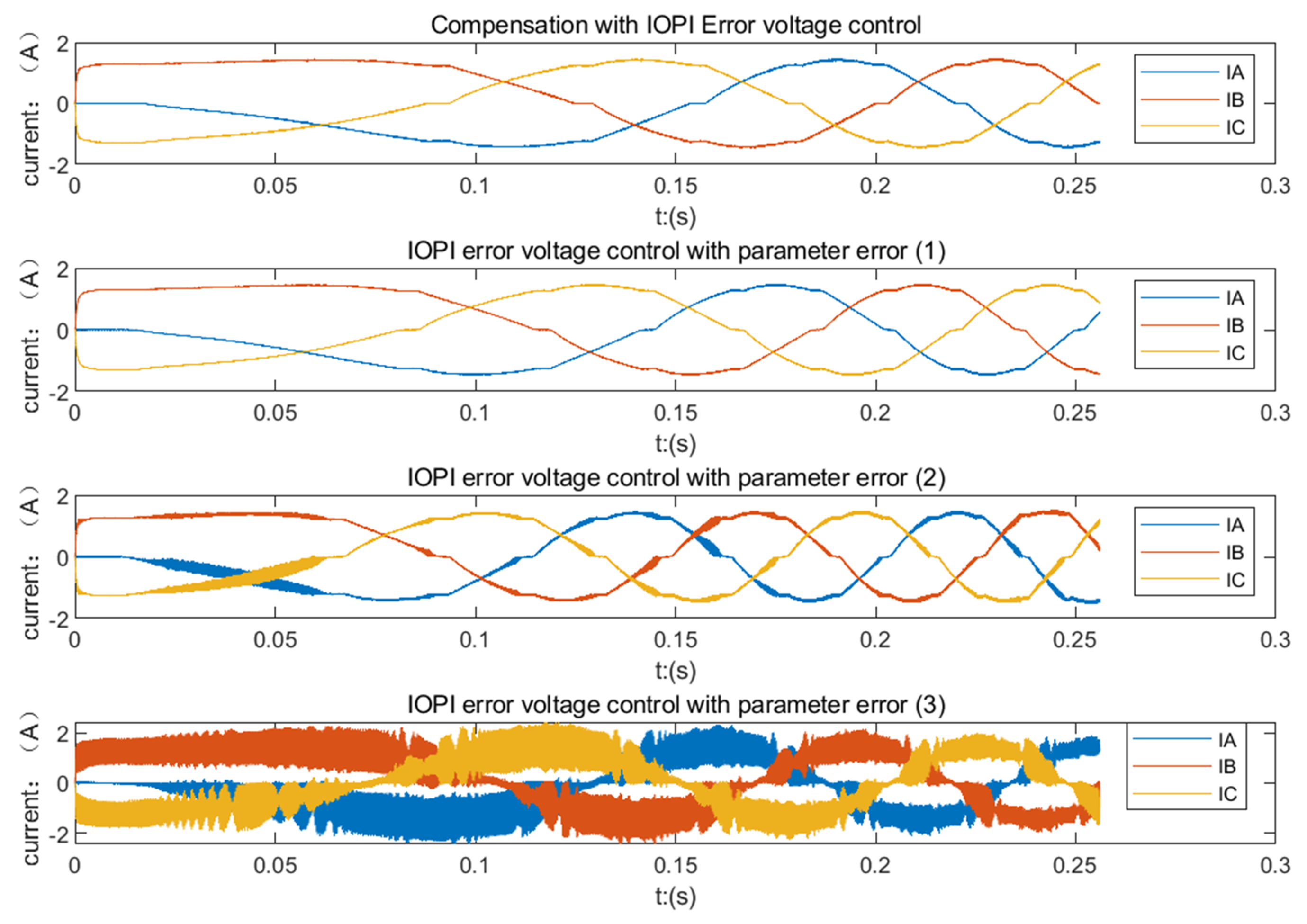
4.3. Robustness Comparison for Motor Parameter Error
Due to the influence of motor characteristics, motor inductance and other parameters are easy to change during the experiment, so the verification of motor parameter uncertainty is added to the simulation. Three groups of motor parameters are randomly given within a certain range for simulation, and the effectiveness and robustness of the compensation method are verified by comparing the optimal FOPI error voltage control method and the optimal IOPI error voltage control method. The error and nominal motor parameters used in the simulation are shown in Table 8.
Table 8.
Three groups of error motor parameters and motor actual parameters.
From Figure 20 and Figure 21, it can be seen that the FOPI error voltage control method still has a good control effect when the motor parameter error occurs. The FOPI error voltage control method can effectively suppress the high-frequency harmonic disturbance caused by the motor parameter error. The control effect of the IOPI controller is poor, and the high-frequency harmonic disturbance cannot be effectively suppressed.
Figure 20.
The comparison of step current response in the error motor parameters.
Figure 21.
The comparison of step current response in the error motor parameters.
It can be seen from Figure 22 and Figure 23 that in the case of errors in motor parameters, FOPI error voltage control still has good performance in eliminating the current clamping phenomenon and suppressing high-frequency harmonic disturbances. The control effect of FOPI error voltage control is better than that of IOPI error voltage control when there are errors in motor parameters, which proves the necessity of using the FOPI controller.
Figure 22.
The three-phase current response of the optimal IOPI error voltage control in the error motor parameters.
Figure 23.
The three-phase current response of the optimal FOPI error voltage control in the error motor parameters.
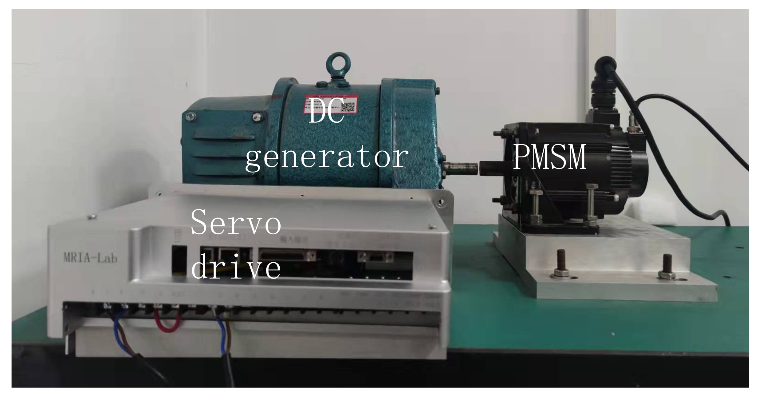
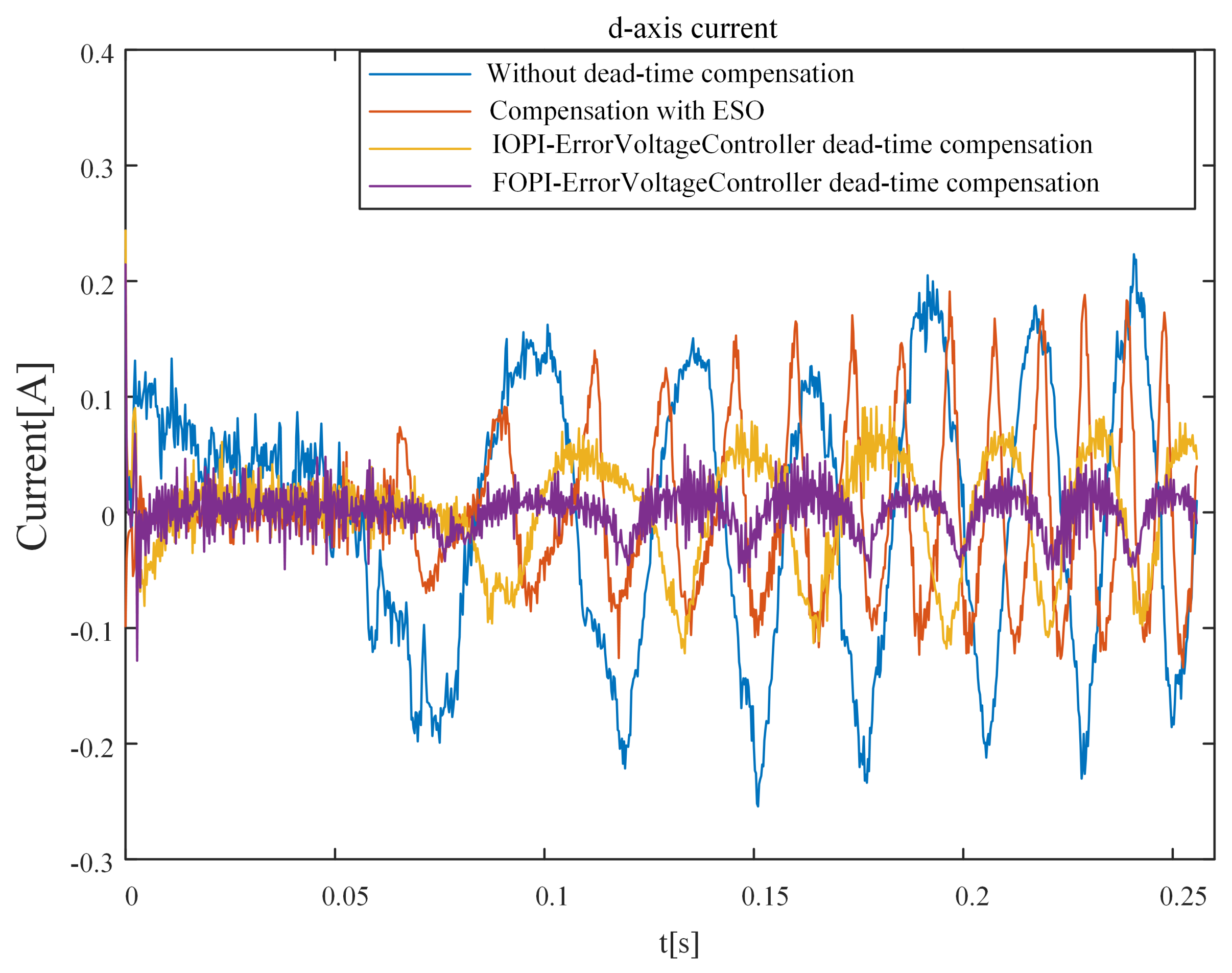
5. Experimental Results
Experiments are performed under the same operating conditions as the simulation to demonstrate the effectiveness and high performance of the method with optimal FOPI control. A laboratory permanent magnet synchronous motor (PMSM) speed servo platform is shown in Figure 24. The experiments’ dead-time setting, controller, and motor parameters are consistent with the simulation. The servo drive is based on the digital signal processor (DSP) TMS320F28335, which is used for AD conversion, encoder sampling, generation of insulated-gate bipolar transistor (IGBT) gate switching signals, and control algorithm implementation.
Figure 24.
Experimental platform.
The experimental comparison results of the current step response are shown in Figure 25 and Table 9. The current step response without compensation has the characteristics of a slow rise time and large ripple. Compared with the IOPI error voltage controller and the compensation with ESO [14], it can be seen that the method with optimal FOPI error voltage control can further improve the tracking performance and reduce the current ripple of the current. Compared with the compensation with ESO [14], the optimal FOPI error voltage control can effectively suppress high-frequency harmonic disturbance.
Figure 25.
Comparison of current response.
Table 9.
The performance index comparison of step current response in the experimental.
In the experimental results, the current response is compared under the three control strategies in Figure 26 and Table 10. Compared with the method without compensation, the dead-time compensation method with optimal IOPI error voltage control and the compensation method with ESO [14] can significantly reduce the current disturbance caused by the dead-time effect. The method with optimal FOPI error voltage control can further reduce the ripple of the current than the method with optimal IOPI error voltage control and the compensation method with ESO [14].
Figure 26.
Comparison of current response.
Table 10.
The performance index comparison of step current response.
The experimental results of the d-axis voltage error are shown in Figure 27. It can be seen that the d-axis error voltage fluctuates violently under the influence of the dead-time effect. Compared with the method without compensation and optimal IOPI error voltage control, the dead-time compensation method with optimal FOPI error voltage control can significantly reduce the d-axis error voltage.
Figure 27.
Comparison of the error voltage of d-axis.
The q-axis error voltage experimental results are shown in Figure 28. The experimental results of q-axis error voltage are consistent with the simulation results. Without compensation, the q-axis error voltage changes nonlinearly with the speed change. The error voltage can converge to 0 quickly when using the method with optimal FOPI error voltage control. The convergence speed of the method with optimal FOPI error voltage control is faster than that using optimal IOPI error voltage control.
Figure 28.
Comparison of the error voltage of q-axis.
The above experiment studies the dead-time effect compensation effect of the method proposed in this paper in the case of current closed-loop control. Add a speed closed-loop controller to the previous current closed-loop control system, and the output of the speed closed-loop controller is used as the reference input of the current controller. When the speed is 40 r/min and 200 r/min, the experimental results of the three-phase current of the permanent magnet synchronous motor are shown in Figure 29 and Figure 30.
Figure 29.
Comparison of Ia current response under 40 r/min speed conditions.
Figure 30.
Comparison of three-phase current response under 200 r/min speed conditions.
The comparison of A-phase current response experimental results under the 40 r/min speed conditions is shown in Figure 29 and Table 11. Compared with the method without compensation and optimal IOPI error voltage control, the dead-time compensation method with optimal FOPI error voltage control can significantly eliminate the current distortion and reduce the clamping of current around the zero-crossing point. The three-phase current clamping time of the method proposed in this paper is less than that of the compensation method using ESO.
Table 11.
The performance index comparison of current step current response under 40 r/min speed conditions.
The comparison of A-phase current response experimental results under 200 r/min speed conditions is shown in Figure 30 and Figure 31.
Figure 31.
Frequency domain analysis of A phase current under 200 r/min speed conditions (the proposed method, the method with optimal IOPI error voltage control and the method with ESO).
In the case of keeping the motor speed constant at 200 r/min, compare the method proposed in this paper with the typical current harmonic elimination method [4]. Further, observe and compare the three-phase current and its frequency spectrum. The three-phase current experiment results and their spectrum analysis of the dead-time-related harmonic minimization method and the method [4] proposed in this paper are shown in Figure 32 and Figure 33. It can be seen from Figure 18 that the proposed method can more effectively eliminate the current clamping phenomenon caused by the dead-time effect. At the point where the current passes through 0, the current clamping time of the proposed method is shorter than the dead-time-related harmonic minimization method [4]. It can be seen from Figure 19 that the proposed method is better than the dead-time-related harmonic minimization method [4] in eliminating the dead-time effect harmonics.
Figure 32.
Comparison of three phase current respons under 200 r/min speed conditions.
Figure 33.
Frequency domain analysis of A phase current under 200 r/min speed conditions (the method with optimal IOPI error voltage control and the minimization method of deadtime-related harmonic).
6. Conclusions
This paper presents a dead-time compensation method for PMSM Servo System with optimal FOPI error voltage control. In this method, the disturbance voltages caused by the power devices’ dead time and nonideal switching characteristics are compensated for by the FOPI controller and fed to the reference voltage. With the same parameter design method and parameter design index, the dead-time compensation method with optimal FOPI error voltage control is compared with the compensation method with ESO and the method with optimal IOPI error voltage control. In order to prove that the FOPI error voltage control method has a good ability to eliminate current harmonics, the dead-time-related harmonic minimization method using optimal PI parameters is compared with the proposed method. The simulation and experimental results demonstrate that the dead-time compensation method with optimal FOPI error voltage control can make the current ripple smaller and the response speed faster. Additionally, the proposed method significantly eliminates the current distortion and reduces current clamping around the zero crossing point. Through theoretical and experimental analysis, it is proven that the method proposed in this paper can have good error voltage control performance and robustness in the case of motor parameter errors. It is proven that the proposed dead-time compensation method can improve the performance of the current response by eliminating the dead-time effect.
Author Contributions
Ideas, software, validation, investigation, writing comments and editing: F.L. and Y.L. Review, commentary: X.L., P.C. and Y.C. All authors have read and agreed to the published version of the manuscript.
Funding
This work was supported by the National Natural Science Foundation of China [51975234].
Conflicts of Interest
The authors declare no conflict of interest.
References
- Lewicki, A. Dead-time effect compensation based on additional phase current measurements. IEEE Trans. Ind. Electron. 2015, 62, 4078–4085. [Google Scholar] [CrossRef]
- Mannen, T.; Fujita, H. Dead-Time Compensation Method Based on Current Ripple Estimation. IEEE Trans. Power Electron. 2015, 30, 4016–4024. [Google Scholar] [CrossRef]
- Dafang, W.; Bowen, Y.; Cheng, Z.; Chuanwei, Z.; Ji, Q. A Feedback-Type Phase Voltage Compensation Strategy Based on Phase Current Reconstruction for ACIM Drives. IEEE Trans. Power Electron. 2014, 29, 5031–5043. [Google Scholar] [CrossRef]
- Wu, Z.; Ding, K.; Yang, Z.; He, G. Analytical Prediction and Minimization of Deadtime-Related Harmonics in Permanent Magnet Synchronous Motor. IEEE Trans. Ind. Electron. 2020, 68, 7736–7746. [Google Scholar] [CrossRef]
- Tang, Z.; Akin, B. A new LMS algorithm based deadtime compensation method for PMSM FOC drives. IEEE Trans. Ind. Appl. 2018, 54, 6472–6484. [Google Scholar] [CrossRef]
- Qiu, T.; Wen, X.; Zhao, F. Adaptive-linear-neuron-based dead-time effects compensation scheme for PMSM drives. IEEE Trans. Power Electron. 2015, 31, 2530–2538. [Google Scholar] [CrossRef]
- Zhu, H.; Chen, Y.; Lei, H.; Chen, D.; Li, Z. A New Dead-time Compensation Method Based on LMS Algorithm for PMSM. J. Phys. Conf. Ser. 2021, 1754, 012203. [Google Scholar] [CrossRef]
- Liu, G.; Wang, D.; Jin, Y.; Wang, M.; Zhang, P. Current -Detection-Independent Dead-Time Compensation Method Based on Terminal Voltage A/D Conversion for PWM VSI. IEEE Trans. Ind. Electron. 2017, 64, 7689–7699. [Google Scholar] [CrossRef]
- Su, J.H.; Hsu, B.C. Application of small-gain theorem in the dead-time compensation of voltage-source-inverter drives. IEEE Trans. Ind. Electron. 2005, 52, 1456–1458. [Google Scholar] [CrossRef]
- Tang, N.; Brown, I.P. Framework and Solution Techniques for Suppressing Electric Machine Winding MMF Space Harmonics by Varying Slot Distribution and Coil Turns. IEEE Trans. Magn. 2018, 54, 1–12. [Google Scholar] [CrossRef]
- Lin, C.; Xing, J.; Zhuang, X. Dead-Time Correction Applied for Extended Flux-Based Sensorless Control of Assisted PMSMs in Electric Vehicles. Electronics 2021, 10, 220. [Google Scholar] [CrossRef]
- Miyama, Y.; Hazeyama, M.; Hanioka, S.; Watanabe, N.; Daikoku, A.; Inoue, M. PWM Carrier Harmonic Iron Loss Reduction Technique of Permanent-Magnet Motors for Electric Vehicles. IEEE Trans. Ind. Appl. 2016, 52, 2865–2871. [Google Scholar] [CrossRef]
- Herman, L.; Papic, I.; Blazic, B. A Proportional-Resonant Current Controller for Selective Harmonic Compensation in a Hybrid Active Power Filter. IEEE Trans. Power Deliv. 2014, 29, 2055–2065. [Google Scholar] [CrossRef]
- Shi, J.; Li, S. Analysis and compensation control of dead-time effect on space vector PWM. J. Power Electron. 2015, 15, 431–442. [Google Scholar] [CrossRef]
- Karttunen, J.; Kallio, S.; Peltoniemi, P.; Silventoinen, P. Current Harmonic Compensation in Dual Three-Phase PMSMs Using a Disturbance Observer. IEEE Trans. Ind. Electron. 2016, 63, 583–594. [Google Scholar] [CrossRef]
- Zhao, Y.; Qiao, W.; Wu, L. Dead-Time Effect Analysis and Compensation for a Sliding-Mode Position Observer-Based Sensorless IPMSM Control System. IEEE Trans. Ind. Appl. 2015, 51, 2528–2535. [Google Scholar] [CrossRef]
- Guha, A.; Narayanan, G. Impact of Dead Time on Inverter Input Current, DC-Link Dynamics, and Light-Load Instability in Rectifier-Inverter-Fed Induction Motor Drives. IEEE Trans. Ind. Appl. 2018, 54, 1414–1424. [Google Scholar] [CrossRef]
- Khurram, A.; Rehman, H.; Mukhopadhyay, S.; Ali, D. Comparative Analysis of Integer-order and Fractional-order Proportional Integral Speed Controllers for Induction Motor Drive Systems. J. Power Electron. 2018, 18, 723–735. [Google Scholar]
- Zheng, W.; Pi, Y. Study of the fractional order proportional integral controller for the permanent magnet synchronous motor based on the differential evolution algorithm. ISA Trans. 2016, 63, 387–393. [Google Scholar] [CrossRef] [PubMed]
- Luo, Y.; Chen, Y. Fractional order [proportional derivative] controller for a class of fractional order systems. Automatica 2009, 45, 2446–2450. [Google Scholar] [CrossRef]
- Luo, Y.; Chen, Y.Q.; Wang, C.Y.; Pi, Y.G. Tuning fractional order proportional integral controllers for fractional order systems. J. Process. Control. 2010, 20, 823–831. [Google Scholar] [CrossRef]
- Choi, J.W.; Sul, S.K. Inverter output voltage synthesis using novel dead time compensation. IEEE Trans. Power Electron. 1996, 11, 221–227. [Google Scholar] [CrossRef]
- Li, Y.; Sheng, H.; Chen, Y. Impulse response invariant discretization of a generalized commensurate fractional order filter. In Proceedings of the 2010 8th World Congress on Intelligent Control and Automation, Jinan, China, 7–9 July 2010; pp. 191–196. [Google Scholar]
- Poli, R. Analysis of the Publications on the Applications of Particle Swarm Optimisation. J. Artif. Evol. Appl. 2008, 2008, 1–10. [Google Scholar] [CrossRef]
- Gaing, Z.L. A particle swarm optimization approach for optimum design of PID controller in AVR system. IEEE Trans. Energy Convers. 2004, 19, 384–391. [Google Scholar] [CrossRef]
- Yoshida, H.; Kawata, K.; Fukuyama, Y.; Takayama, S.; Nakanishi, Y. A particle swarm optimization for reactive power and voltage control considering voltage security assessment. IEEE Trans. Power Syst. 2000, 15, 1232–1239. [Google Scholar] [CrossRef]
- Karaboga, D.; Basturk, B. A powerful and efficient algorithm for numerical function optimization: Artificial bee colony (ABC) algorithm. J. Glob. Optim. 2007, 39, 459–471. [Google Scholar] [CrossRef]
- Wang, B.; Wang, S.; Peng, Y.; Pi, Y.; Luo, Y. Design and High-Order Precision Numerical Implementation of Fractional-Order PI Controller for PMSM Speed System Based on FPGA. Fractal Fract. 2022, 6, 218. [Google Scholar] [CrossRef]
Disclaimer/Publisher’s Note: The statements, opinions and data contained in all publications are solely those of the individual author(s) and contributor(s) and not of MDPI and/or the editor(s). MDPI and/or the editor(s) disclaim responsibility for any injury to people or property resulting from any ideas, methods, instructions or products referred to in the content. |
© 2023 by the authors. Licensee MDPI, Basel, Switzerland. This article is an open access article distributed under the terms and conditions of the Creative Commons Attribution (CC BY) license (https://creativecommons.org/licenses/by/4.0/).