Abstract
Digital twins are applied in smart manufacturing towards a smarter cyber-physical manufacturing system for effective analysis, fault diagnosis, and system optimization of a physical system. In this paper, a framework applying a digital twin to industrial robots is proposed and realizes the real-time monitoring and performance optimization of industrial robots. This framework includes multi-domain modeling, behavioral matching, control optimization, and parameter updating. The properties of the industrial robot are first modeled in a digital environment to realize the strong interactive and all-around 3D visual monitoring. Then, behavioral matching is performed to map the virtual system to the physical system in real time. Furthermore, the control performance of the system is improved by using a fractional order controller based on the improved particle swarm optimization algorithm. This framework is applied to the experimental verification of real-time control optimization on an industrial robot. The time-domain performance is improved in the simulation and experimental results, where the overshoot is promoted at least 42%, the peak time is promoted at least 32%, and the settling time is promoted at least 33%. The simulation and experimental results demonstrate the effectiveness of the proposed framework for a digital twin combined with fractional order control (FOC).
1. Introduction
With the development and application of new information technologies, countries have proposed different manufacturing strategies [1], and smart manufacturing is a common way to improve the level of the manufacturing industry [2]. Smart manufacturing requires not only high quality standards but also enhanced robustness and autonomy to achieve production targets [3]. Most of the work is related to the physical system, and the content of the digital system only plays an auxiliary role most of the time in traditional manufacturing [4].
Compared with smart manufacturing, the innovation cycle of the traditional industrial field is much longer. Therefore, one of the key challenges is to achieve Cyber-Physical Systems (CPS) [5]. CPS realizes real-time interactions and close combinations of the network and the physical systems through computing, communication, and control [6]. To achieve this transformation, an emerging technology is urgently needed—namely, digital twins [7].
The digital twin concept was officially proposed in NASA’s technical report in Mid-2010 [8]. The key of a digital twin is to create a virtual model of the physical system in a digital way and then simulate, verify, control, and predict the whole life cycle process of the physical system with the help of the digital twin data, the virtual system, and the connection between physical and virtual systems [9]. With the development of smart manufacturing, the application of digital twins in the manufacturing industry has been widely studied [10].
Tao et al. constructed a general digital twin framework for complex equipment, which is used for prognostics and health management to improve accuracy and efficiency [11]. Rodolfo et al. presented a digital twin-based optimization procedure for an ultra-precision motion system [12]. Aivaliotis et al. presented a methodology to calculate the remaining useful life (RUL) of machinery equipment using physics-based simulation models based on the digital twin concept, and the RUL of industrial robots was predicted effectively [13].
Zhang et al. proposed an optimal state control framework based on digital twins, which helps the synchronized production operational system maintain an optimal state when uncertainties effect the system [14]. Viola et al. applied a digital twin to the framework of intelligent control engineering. The framework reproduced the system behavior through a multi-domain simulation and completed the real-time interface between physical and virtual systems by adjusting the behavioral matching technology to the digital twin [3].
Gallala et al. proposed a digital twin approach for human–robot interactions (HRIs) in hybrid teams; however, this approach lacked a description of performance optimization [15]. Lei et al. presented a web-based digital twin thermal power plant and discussed the architecture, modeling, control algorithm, rule model, and physical–digital twin control, which is beneficial to study the applications of digital twinning in other fields [16].
However, implementing digital twins to industrial motion systems still lacks a thorough understanding of the concept, framework, and development methods, which hinders the progress of real digital twin application in smart manufacturing [17]. There are two major research questions that need to be solved: (1) how to match the virtual model with the actual motion state in real time to ensure the accuracy of the model in the optimization process; and (2) how to further optimize the control performance of the physical system in the proposed digital twin framework.
The greatest challenge for the first question is how to construct real-time behavioral matching based on an optimal algorithm to ensure the accuracy of the virtual model. The real-time interaction is realized through the database. The digital twin data collected from the virtual and physical system, including static and dynamic model information of the physical system, information collected by sensors during physical system operation, and information collected by virtual sensors during virtual system operation, are all stored in the database.
Digital twin data can be read at any time as a database client. Then, the real-time interaction between the physical and the virtual systems can be realized, which lays a solid foundation for the accuracy and effectiveness of the virtual model optimization. In order to achieve intelligent optimal control, the methods of introducing artificial intelligence algorithms to optimize the performance of the control system can be divided into two categories.
One is to use artificial intelligence algorithms directly for control [18], thereby, replacing the traditional controllers. The other is to combine the approach with classical control theory and use artificial intelligence algorithms for parameter tuning [19]. As for the second question, the proposed methodology in this paper is fractional order control (FOC) optimization using artificial intelligence algorithms in a digital twin framework to achieve optimal control performance.
Fractional calculus is the quantitative analysis of functions using non-integer-order integration and differentiation [20], and this has attracted a great deal of interest in system modeling and control fields [21]. Fractional order controllers have been found to obtain more control options and flexibility compared with integer order controllers [22]. Among them, the fractional order PID was proposed by I. Podlubny [23]. Due to the fact that the fractional order PID controller achieves better tracking performance with less overshoot and faster response [24], the fractional order PID controller has been widely used in the control fields [22,25].
Therefore, the fractional order PID controller design and optimization method is proposed in the industrial robot motion system digital twin framework in this paper. There exist some tuning methods of fractional order controllers, which can be divided into two categories: the frequency-domain-design method and time-domain optimization algorithms.
The frequency-domain-design method generally refers to the numerical solution of the parameters of the controller by specifying the frequency specifications, combined with the robustness criterion [26]. According to the frequency-domain-design method, the parameters of the controller can be obtained through analytical calculation, which can realize effective control of the system [27]. Monje et al. proposed a design scheme of fractional order controller with given frequency-domain indexes, which is robust to equipment uncertainty, load disturbance and high-frequency noise [28].
Chen et al. used the frequency-domain-design scheme to design the parameters of FOPID-BICO, which ensures the robustness and anti-interference of the control system [29]. However, there exist some problems, including the parameter limitation for optimization, the complexity of the algorithm, and a large amount of calculation for the real-time optimization process. Time-domain-optimization algorithms have also been developed [30], which overcome the uncertainty and cumbersomeness of manually adjusting parameters by introducing intelligent optimization algorithms.
The major contributions of this paper are as follows: (1) we introduce a framework of a digital twin for industrial motion system, which realizes real-time monitoring and optimization of the running state with experimental verification of control optimization; (2) digital twin behavioral matching based on real-time data analysis and dynamic mapping between virtual system and physical systems; and (3) FOC optimization using the intelligent algorithm in the digital twin framework to achieve optimal motion system performance.
This paper is structured as follows. Section 2 presents the framework of a digital twin for industrial robots and introduces the four phases of implementation in detail. Section 3 shows the implementation of the proposed framework using related software. Section 4 describes the specific application example, which is how to implement the digital twin framework on an industrial robot control system. Section 5 presents the simulation and experimental results to demonstrate the effectiveness and advantages of the proposed digital twin framework combined with FOC optimization. Finally, our conclusions and future work are presented in Section 6.
2. Digital Twin Approach
The idea of a digital twin first appeared in the product lifecycle management course taught by Grieves around 2003. In 2014, he further elaborated on digital twins in a white paper and proposed a general standard system on digital twin, which is a three-dimensional structure [31]. This three-dimensional architecture consists of three main objects—namely, physical products in real space, virtual products in virtual space, and the connections of data and information that tie the virtual and physical products together.
In order to improve the accuracy and efficiency of prognostics and health management for complex systems, Tao proposed an extended five-dimension digital twin architecture, which adds digital twin data and services based on the Grieves’ architecture [11]. In addition, other digital twin architectures have been proposed by other researchers [32]. Referring to Tao’s five-dimensional model of digital twins, this paper presents a five-dimensional architecture of digital twins applied to industrial robots as shown in Figure 1.
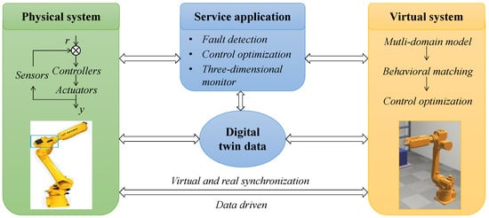
Figure 1.
A five-dimensional framework of digital twins: applications to industrial robots.
This framework also consists of five aspects—namely, the physical system, virtual system, digital twin data, service applications, and the connection between the above four aspects. The virtual system is built based on the physical system and digital twin data first, adjusted to realize real-time synchronization to the physical system, and then optimized according to the service applications proposed by physical systems, such as fault detection, control optimization, and three-dimensional monitoring. Finally, the monitoring and optimization of the physical system can be realized based on the digital twin data stored after the virtual system optimization.
In classical control theory, it is necessary to manually adjust the parameters based on the error signal through the control algorithm offline, which is a slow, tedious, and inefficient process. The framework in this paper focuses on the utilization of the digital twin concept to automatically adjust the controller parameters when the operating state of the robot changes. More specifically, a real-time optimization strategy for FOC is proposed in the framework, which can achieve optimal tracking control and robustness performance.
Based on the service application of three-dimensional monitoring and control optimization, the framework is composed of four steps: multi-domain modeling, behavioral matching, control optimization, and parameter updating.
2.1. Multi-Domain Modeling
The purpose of the first step is to establish a virtual system representing the behavior of the physical system. As a copy of the physical system, the virtual system needs to truly reflect the state of the physical system at every moment to realize monitoring of the physical system.
The modeling process includes two parts as depicted in Figure 2: the first part is to model the position, geometric size, material, and dependency of the physical system; and the second part is to model the kinematic and dynamic characteristics of the physical system, which is also the most important part of the modeling.
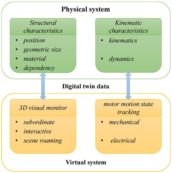
Figure 2.
A multi-domain model as a virtual system based on a physical system.
The first part of modeling is to represent the model of robot and its environment in 3D. The target is to realize the strong interactive and all-around 3D visual monitoring effect of the physical entities. The second part of modeling is to achieve motor motion state tracking. The complete model of each motor consists of a number of elements, which represent the dynamic behavior of each motor’s component based on the modeling of the mechanical, electrical, and other functions.
2.2. Behavioral Matching
The purpose of this step is to find the parameters of the virtual model so that the virtual model can adapt to its complete system dynamics and be consistent with the real state of the physical system. The parameters of the virtual model can be divided into two parts. The first part is all available data related to the physical system. It is worth mentioning that most of the modeled elements can use the parameters directly from collection.
The second part of the parameters will change continuously due to the operation of the machine and other external factors and cannot be defined directly using the collected data. These parameters need to be optimized online in real time by using the digital twin data to achieve the target of the behavior of the virtual system matching the behavior of the physical system. This process is called behavioral matching [3] as depicted in Figure 3.
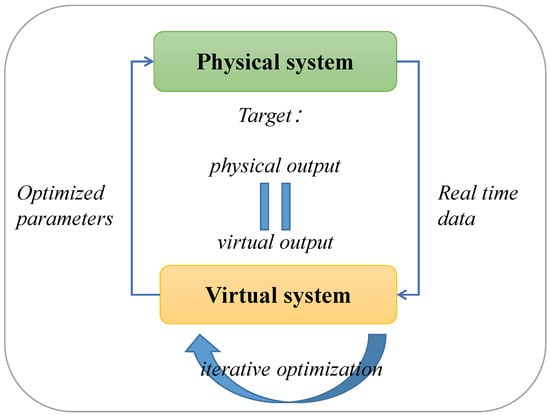
Figure 3.
Behavioral matching.
This process is set as an optimization cycle. Intelligent optimization algorithms are used to optimize the parameters. The cost function will be computed continuously until the input and output data streams of the system are consistent with a certain tolerance rate or after a fixed number of iterations.
2.3. Control Optimization
The purpose of this step is to optimize the control performance of the virtual model. After behavioral matching, the mapping and interactions between the physical system and virtual system are deployed. Therefore, the control performance optimization of the virtual model is of great significance to the optimization of physical system. In order to achieve better control performance, the fractional order controller is used to control and optimize based on the accurate virtual model.
There exist some tuning methods of fractional order controllers, which can be divided into two categories: frequency-domain-design method and time-domain-optimization algorithms. To overcome the uncertainty and cumbersomeness of manually adjusting parameters, the intelligent optimization algorithm is used in this paper. Using optimal control rules, we first calculating the error between the reference and feedback of the closed-loop system, and then using the optimization algorithms and tools to minimize the cost function value representing the dynamic performance index of the system, and search for the optimal parameters. The time-domain-optimization algorithm is applied in the proposed digital-twin-system framework with data collection from the physical system to the virtual system as shown in Figure 4.
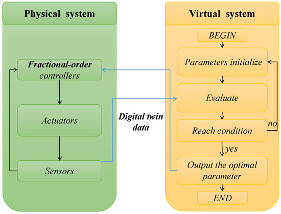
Figure 4.
Digital-twin-system framework control optimization.
2.4. Parameter Updating
The purpose of this step is to update the optimal parameters obtained by the virtual system to the physical system to achieve the predetermined control targets. The iteratively optimized parameters are stored in the virtual system and are updated in the physical system through the data communication channel between the virtual and physical systems. By optimizing the controller parameters in real time, the high performance index can be maintained when the running state of the physical system changes.
3. Digital Twin Deployment
The previous section describes a framework of digital twins for the industrial motion system. The implementation of multi-domain modeling with related software and behavioral matching of the framework are presented in this section. Multi-domain modeling is divided into two parts. The first part is to model the position, geometric size, material, and dependency of the physical system, which is performed in Unity3D [33]. The 3D platform used to build the model needs to follow three rules: 3D visualization requirement, key function requirement, and cross-platform operation requirement.
Furthermore, as a popular virtual system development engine, Unity3D is used to build 2D and 3D scenes, and add scripts, shaders, and physical features to scenes. Thus, Unity3D can be used to model the virtual 3D environment. There are two modeling methods of Unity3D. One is to build the components by users in Unity3D and build the components hierarchically according to the principle of behavioral consistency; the other is to import the model directly, which is actually the most general method [34].
Then, the correct subordinate relationship should be established in virtual model based on the hierarchical structure of the physical system according to the design principles of hierarchical consistency and behavioral consistency. Through the strong interaction and scene roaming function of Unity3D, the omni-directional real-time visual monitoring of the physical system can be realized.
The second part of multi-domain modeling is to model the kinematic and dynamic characteristics of the physical system in MATLAB Simulink, which is a well-known multi-domain simulation and model-based design tool and can provide the environment for modeling, simulation, and comprehensive analysis of dynamic systems as well as an interactive graphical environment and a customizable module library for design, simulation, execution, and testing.
Thus, the behavioral matching and control optimization process can be directly performed in MATLAB. After behavioral matching, the four parameters in the electromechanical model can be obtained to make the behavior of the virtual model closer to that of the physical system. After control optimization, the parameters of the controller will be obtained to optimize the control performance of the virtual system. These parameters are all stored as digital twin data.
As multi-domain modeling, behavioral matching, and control optimization are all supported by digital twin data, including sensor data, control state data in the physical system and simulation data in the virtual system. Therefore, a database structure needs to be built to store all digital twin data generated in real time. In this paper, Mysql as a C/S architecture [35] is applied to build the database. A server is used to store and manage the database, and the client is the program that issues the operation request.
Furthermore, Mysql can store data for each period of time during the running process. After completing the behavioral matching of the virtual system, optimizing the controller parameters based on the accurate model, and sending the optimized controller parameters back to the physical system for control, it is achievable by monitoring the digital twin data to verify whether the performance of the physical system has been improved.
4. A Case Study
A case study on the industrial robot has taken place to demonstrate the functionality of the proposed framework. In order to describe the above proposed framework in more detail, each stage is described in the case study.
4.1. Multi-Domain Modeling
The robot studied in this case study is the EFORT ER20C-C10 as a six-axes robot, which has six rotating joints, and each axis is driven by a permanent magnet synchronous motor (PMSM). One of the six axes on this industrial robot is focused on in this paper to build a digital twin model.
The first part is to model the position, geometric size, material, and dependency of the physical system. The second method is adopted in this paper to construct Unity3D model, which is to directly import the model. Furthermore, the correct subordinate relationship is established in the virtual model based on the hierarchical structure of the physical system. Then, the interactive functions and scene roaming functions are added to the virtual system scene. Furthermore, through the digital twin data collected by the data interface, the function of running state reproduction can be realized. The model established in Unity3D is shown in Figure 5.
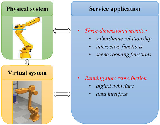
Figure 5.
Model of six-axes robot in Unity3D.
The second part is to model the kinematic and dynamic characteristics of the physical system. The PMSM model of the robot axis consists of an electromagnetic link model and mechanical link model; the former conforms to the voltage equation, and the latter conforms to the mechanical characteristic equation as follows:
where, in (1), u is the armature voltage, is the back EMF coefficient, n is the motor speed (the unit is rpm), R is the armature resistance, is the armature current, and L is the armature inductance; in (2), is the electromagnetic torque, is the equivalent torque of load, is the motor angular speed (the unit is rad/s), B is the damping coefficient, and J is the moment of inertia.
Figure 6 shows the speed servo system of PMSM, where the electromagnetic part is in the red dashed block, and the mechanical part is in the green dashed block. and n are the reference motor speed and actual motor speed, respectively; i and i are the reference q-axis current and actual q-axis current feedback, respectively; u is the q-axis voltage; and E is the back EMF. C(s) is the speed controller to be designed, and C(s) is the current controller to be designed. In order to optimize the control performance in the physical system, a fractional order controller is designed in this control system. In the simulation and experiment, the cascaded fractional order PI-PI controller and the cascaded integer order PI–PI controller are designed with controller optimization for a fair control performance comparison.
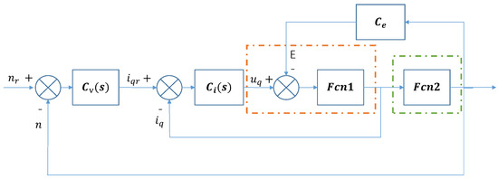
Figure 6.
The permanent magnet synchronous motor (PMSM) speed closed−loop control system.
4.2. Behavioral Matching
In order to meet the requirements of real-time mapping of the physical system to the virtual system, behavioral matching is performed based on the established model with real-time adjustment of parameters. In this case, the parameters of the electromechanical model are the most relevant for building the accurate virtual model. Therefore, the four parameters in the electromechanical model, including the moment of inertia, damping coefficient, resistance, and inductance—namely, J, B, R, and L are the parameters for behavioral matching. Then, we evaluate whether the identified four parameters can match the virtual system behavior with the physical system behavior.
Based on the parameter identification method in [36], the transfer function model of each part in Figure 6 can be obtained as
The data used for behavioral matching is derived from the digital twin system, including data collected by sensors in the physical system and also simulated statutes in the virtual system. The input data collected from the physical system sensor is taken as the input of the virtual system model. Then, the output data collected from the physical system sensor and the output data of the virtual model are compared as the cost function for parameter optimization,
where is the output of the physical system, is the output of the virtual system, and t is the time.
The optimization algorithm used in this case is an improved particle swarm optimization algorithm. The concept of the standard PSO algorithm is simple, and it has a short-term memory function, which makes particles slide in the local optimal or global optimal position. However, the population is prone to premature convergence, and improper setting of inertial weight will lead to a local optimal solution [37]. In order to overcome the tendency of falling into useless solutions and improve its convergence, some improved particle swarm optimization algorithms were proposed [38].
The inertia weight directly affects the search speed and accuracy of the algorithm [39]. When the inertia weight is large, the global search ability of the particle is enhanced. When the inertia weight is small, the local search ability of the particle is improved, which is conducive to improving the search accuracy of the particle. Therefore, it is expected that the inertia weight of the algorithm is large in the early stage but becomes smaller in the late stage. In this paper, the method of dynamically changing the inertia weight is proposed to improve the performance of the particle swarm optimization algorithm.
This optimization algorithm is used to perform iterative optimization of the parameters by minimizing the cost function. The optimization cycle ends when the cost function reaches the allowable error range or the number of iterations is reached. In this case, the number of iterations is set as 50. The convergence process of the cost function in behavioral matching is shown in Figure 7. After behavioral matching, the parameters can be updated in the virtual model as shown in (6) and (7) and stored in the database as digital twin data.
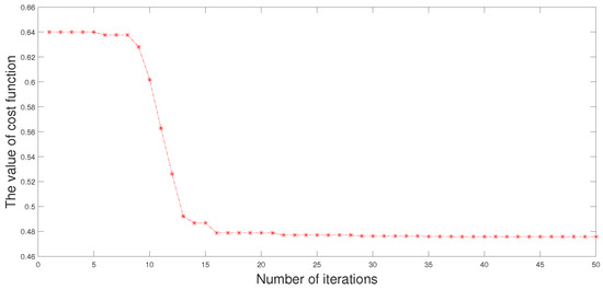
Figure 7.
The convergence process of behavioral matching applying the improved particle swarm optimization algorithm.
4.3. Control Optimization
After the behavioral matching phase is done, the virtual system is called the twin of the physical system. This step is based on the accurate virtual model to optimize the control performance. The parameters of the controllers are also optimized by the improved particle swarm optimization algorithm. The optimization procedures are as follows:
4.3.1. Define the Parameter Search Scope
The four parameters of the cascaded integer order PI–PI controller and the six parameters of the cascaded fractional order PI-PI controller are considered as the solution set. Then, we initialize the parameters of the particle swarm optimization algorithm by randomly initializing the position and initial velocity of the particle. The size of the particle swarm is set as 100, and the maximum number of iterations is set as 50. A linearly decreasing inertia weight is used, which starts with set as 0.9 and ends with set as 0.4. The learning factors and are set as 0.9.
4.3.2. Choose a Fitness Function
The commonly used comprehensive performance evaluation standards are mainly based on the relationship between the deviation of the system w.r.t the time t. Generally, the performance index functions of the control system can be the error absolute value integral (IAE), the error square integral (ISE), the integral of timed square error (ITSE) or the absolute value of the error multiplied by the time integral (ITAE). IAE and ISE are not restricted by time, which is easy to cause the contradiction of reducing the overshoot and reducing time.
Furthermore, ITSE focuses on the error that occurs in the later stage of the transient response but seldom considers the large initial error in the response. For fast, stable, and small overshoot systems, ITAE is one of the commonly used performance indicators. The fitness function chosen in this paper is ITAE. The initialization process of the algorithm is as follows: the fitness of each particle is calculated according to the fitness function, and then the optimal individual is found in the initialized particle swarm, which is initialized to the optimal population, and the optimal fitness of the particle itself to a single particle is initialized.
4.3.3. The Iterative Optimization
At the time , as shown in Figure 8, the inertia weight decreases linearly during the iteration, and the particle position is updated as follows:
where is the weight of the inertia at time t, which balances the global search and local search; K is the maximum number of iterations; r and r are random numbers in the interval (0,1); and are the velocity of the particle at time t and , respectively; and are the positions of the particle at time t and , respectively; is the personal best position at time t; and is the global best position at time t.
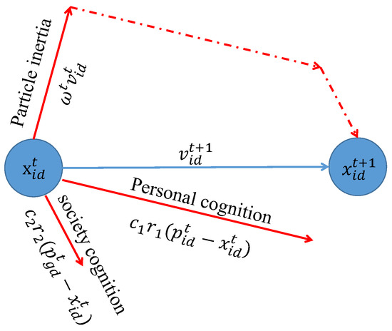
Figure 8.
Iterative graph of the particle swarm optimization.
Then, the updated particle fitness is calculated and compared. Furthermore, the particle’s own optimal fitness and the global optimal fitness are updated.
4.3.4. End Condition Judgment
Judge whether the maximum number of iterations is reached or the fitness function reaches the error tolerance range, if not, jump to (3), else, jump out of the loop. The convergence process of ITAE value in control optimization is shown in Figure 9.
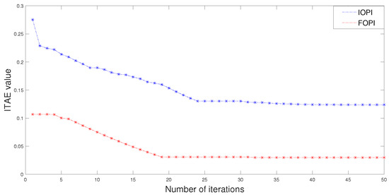
Figure 9.
The convergence process of controller parameter optimization applying the improved particle swarm optimization algorithm.
4.3.5. Output Optimized Parameters
The output global optimal particles are the four parameters of the cascaded integer order PI–PI controller or the six parameters of the cascaded fractional order PI-PI controller.
4.4. Parameter Updating
The data transmission flow chart of the process is shown in Figure 10. First, the operating data of the industrial robot is collected by sensors and stored in MySQL as digital twin data. Then, the virtual system is modeled and optimized based on the digital twin data. The controller parameters obtained by iterative optimization in the virtual system need to be updated in the physical system to realize the control optimization of the physical system. Thus, the optimized parameters are stored in the database as the Mysql client, and Unity3D reads the digital twin data stored in the Mysql server and transmits the parameters to the controller through Socket communication.
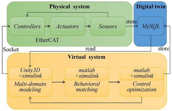
Figure 10.
The data transmission flow chart of parameter updating.
The controller uses EtherCAT to transmit data to the driver with a transmission frequency of 500 Hz and then updates the controller parameters. After the controller parameters are updated, the running state data of the physical system operation process is collected again to verify whether the parameters obtained through virtual model simulation optimization have an optimal effect on the behavior of the physical system.
4.5. Summary
According to the above case study, the whole six-axes industrial robot is modeled in unity3D, and then the PMSM of the single axis is modeled in Simulink to realize the virtual mapping of the fourth axis running state. It means that the running action of the robot can be clearly observed through unity3D, while the running state of the single axis can be well observed through Simulink. The real-time data obtained from the sensor of the physical system and the simulation of the virtual model are collected to identify the behavior of components and adjust their virtual model accordingly.
The four parameters with the greatest influence on the PMSM model (namely, J, B, R, and L) are evaluated. Based on the iterative algorithms and real-time digital twin data, the four parameters are adjusted in real time. The virtual model after behavioral matching can better match the real running state of the physical system compared with the initially identified model and can truly realize the real-time mapping between the physical system and the virtual system.
Then, the controller parameters can be optimized based on this accurate virtual model. The optimized parameters are transmitted back to the controllers of the physical system reliably in real time to achieve better performance. Finally, simulations and experiments are conducted in the next section to show the feasibility and effectiveness of the proposed framework.
5. Simulation and Experiment
The motor step-response operation reference value is 400 rpm. Figure 11 shows the results of behavioral matching, in which the blue line is the speed–output data curve collected during motor operation, the green line is the speed–output data curve obtained by simulation based on the identified model, and the red line is the speed–output data curve obtained by simulation based on the model after behavioral matching. In Figure 11a, both the physical system and the virtual system adopt the controller parameters originally set in the physical system.
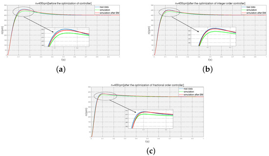
Figure 11.
Verify the effectiveness of behavioral matching before and after the controller parameter optimization. (a) Step response comparison with the initial integer order controller parameters of physical system. (b) Step response comparison with the optimized integer order controller parameters in the virtual system. (c) Step response comparison with the optimized fractional order controller parameters in the virtual system.
In Figure 11b, both the physical system and virtual system adopt the integer order controller parameters optimized based on the accurate model after behavioral matching. In Figure 11c, both the physical system and the virtual system adopt fractional order controller parameters optimized based on the accurate model after behavioral matching. The differences in Figure 11a–c are in the different controller parameters. The simulation results show that when the controller parameters and even the controller form change, behavioral matching still plays an important role, making the virtual model much closer to the behavior of the physical system.
Figure 12 shows the simulation results of the control parameter optimization based on the accurate model after behavioral matching, in which the blue line is the simulation curve using the cascaded integer order controller parameters in the initial physical system, the green line is the simulation curve using the cascaded integer order controller parameters after optimization, and the red line is the simulation curve using the cascaded fractional order controller parameters after optimization. From the comparison of simulation results, it can be seen that the controller optimization based on the accurate model after behavioral matching improved the performance of the system, including the rise time and overshoot. The fractional order controller performed better than the integer order controller.
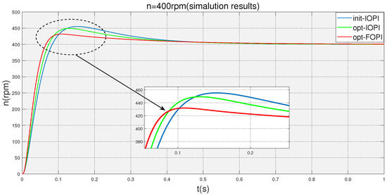
Figure 12.
Simulation result comparison between the optimized fractional order controller and optimized integer order controller based on the accurate model after behavioral matching.
Figure 13 shows the experimental results of control parameter optimization, in which the blue line is the experimental curve using the cascaded integer order controller parameters in the initial physical system, the green line is the experimental curve using the cascaded integer order controller parameters after optimization, and the red line is the experimental curve using the cascaded fractional order controller parameters after optimization.
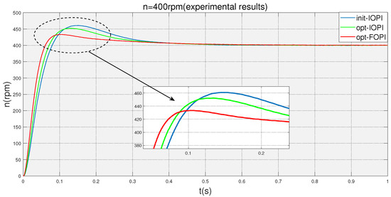
Figure 13.
Experimental result comparison between the optimized fractional order controller and optimized integer order controller based on the accurate model after behavioral matching.
From the comparison of experimental results in Table 1, we also see the effectiveness of real-time optimization based on the proposed digital twin framework for improving physical system performance, including the rise time and overshoot. This also demonstrates that the fractional order controller outperformed the integer order controller.

Table 1.
Step response performances of simulation and experimental results.
6. Conclusions and Future Work
In this paper, we proposed a framework of a digital twin applied to industrial robots and applied it to a specific case. This framework employs four phases: establishing the virtual model of the physical system to reflect the characteristics of the physical system, mapping the physical system behavior in real time by using behavioral matching, optimizing the behavior of the virtual model by using the time-domain-optimization algorithm and fractional order controller, and finishing with the optimized parameters being updated in the physical system.
Using this framework, the mapping and interaction between the virtual system and the physical system can be realized, and the real-time optimization of the physical system based on a digital twin can be achieved. Moreover, by introducing the concept of fractional order into the proposed framework to design the fractional order controller, the optimization effect of the physical system can be improved. The simulation and experimental results show the feasibility and effectiveness of the proposed digital twin framework applied to industrial robots.
As a future activity, further investigation will be conducted for overall virtual modeling and real-time control of the six-axes industrial robot based on a digital twin in order to integrate the proposed framework into more general aspects. Furthermore, the algorithm used in the behavioral matching process and the control optimization process will be optimized to achieve better results.
Author Contributions
Conceptualization, Y.L.; methodology, Y.L. and X.L.; validation, X.L. and H.G.; data curation, X.L. and H.G.; writing—original draft preparation, X.L.; writing—review and editing, Y.L., Y.C. and L.G. All authors have read and agreed to the published version of the manuscript.
Funding
This work was supported by the National Natural Science Foundation of China grant number 51975234.
Data Availability Statement
Not applicable.
Conflicts of Interest
The authors declare no conflict of interest.
References
- Tao, T.; Zhang, M. Digital Twin Shop-floor: A New Shop-floor Paradigm towards Smart Manufacturing. IEEE Access 2017, 5, 20418–20427. [Google Scholar] [CrossRef]
- Zhang, X.; Zhu, W. Application framework of digital twin-driven product smart manufacturing system: A case study of aeroengine blade manufacturing. Int. J. Adv. Robot. Syst. 2019, 16, 1100–1108. [Google Scholar] [CrossRef]
- Viola, J.; Chen, Y. Digital Twin Enabled Smart Control Engineering as an Industrial AI: A New Framework and Case Study. In Proceedings of the 2020 second International Conference on Industrial Artificial Intelligence (IAI), Shenyang, China, 23–25 October 2020; pp. 1–6. [Google Scholar]
- Zhou, J.; Zhou, Y.; Wang, B.; Zang, J. Human–cyber–physical systems (HCPSs) in the context of new-generation intelligent manufacturing. Engineering 2019, 5, 624–636. [Google Scholar] [CrossRef]
- Tao, F.; Cheng, J.; Qi, Q.; Zhang, M.; Zhang, H.; Sui, F. Digital twin-driven product design, manufacturing and service with big data. Int. J. Adv. Manuf. Tech. 2018, 94, 3563–3576. [Google Scholar] [CrossRef]
- Liu, Y.; Peng, Y.; Wang, B.; Yao, S.; Liu, Z. Review on Cyber-physical Systems. CAA J. Autom. Sin. 2017, 4, 27–40. [Google Scholar] [CrossRef]
- Kamel Boulos, M.N.; Zhang, P. Digital twins: From personalised medicine to precision public health. J. Pers. Med. 2021, 11, 745. [Google Scholar] [CrossRef]
- Tuegel, E.; Ingraffea, A.; Eason, T. Reengineering aircraft structural life prediction using a digital twin. Int. J. Aerosp. Eng. 2011, 2011, 1687–5966. [Google Scholar] [CrossRef]
- Qi, Q.; Tao, F. Digital Twin and Big Data Towards Smart Manufacturing and Industry 4.0: 360 Degree Comparison. IEEE Access 2018, 6, 3585–3593. [Google Scholar] [CrossRef]
- Kritzinger, W.; Karner, M.; Traar, G.; Henjes, J.; Sihn, W. Digital Twin in manufacturing: A categorical literature review and classification. IFAC-PapersOnLine 2018, 51, 1016–1022. [Google Scholar] [CrossRef]
- Tao, F.; Zhang, M.; Liu, Y.; Nee, A. Digital twin driven prognostics and health management for complex equipment. CIRP Ann. 2018, 67, 169–172. [Google Scholar] [CrossRef]
- Guerra, R.; Quiza, R.; Villalonga, A. Digital Twin-Based Optimization for Ultraprecision Motion Systems with Backlash and Friction. IEEE Access 2019, 7, 93462–93472. [Google Scholar] [CrossRef]
- Aivaliotis, P.; Georgoulias, K.; Chryssolouris, G. The use of Digital Twin for predictive maintenance in manufacturing. Int. J. Comput. Integr. Manuf. 2019, 32, 1067–1080. [Google Scholar] [CrossRef]
- Zhang, K.; Qu, T.; Zhou, D.; Jiang, H.; Lin, Y.; Li, P.; Huang, G. Digital twin-based opti-state control method for a synchronized production operation system. Robot. Comput.-Integr. Manuf. 2019, 63, 101892. [Google Scholar] [CrossRef]
- Gallala, A.; Kumar, A.; Hichri, B.; Plapper, P. Digital Twin for Human–Robot Interactions by Means of Industry 4.0 Enabling Technologies. Sensors 2022, 22, 4950. [Google Scholar] [CrossRef]
- Lei, Z.; Zhou, H.; Hu, W.; Liu, G.; Guan, S.; Feng, X. Toward a Web-Based Digital Twin Thermal Power Plant. IEEE Trans. Ind. Inform. 2022, 18, 1716–1725. [Google Scholar] [CrossRef]
- Aheleroff, S.; Mostashiri, N.; Xu, X.; Zhong, R. Mass Personalisation as a Service in Industry 4.0: A Resilient Response Case Study. Adv. Eng. Inform. 2021, 50, 101438. [Google Scholar] [CrossRef]
- Wang, Y. Robot algorithm based on neural network and intelligent predictive control. J. Amb. Intel. Hum. Comp. 2020, 11, 6155–6166. [Google Scholar] [CrossRef]
- Zhao, Z.; Liu, S.; Pan, J. A PID parameter tuning method based on the improved QUATRE algorithm. Algorithms 2021, 14, 173. [Google Scholar] [CrossRef]
- Niu, H.; Chen, Y.; West, B. Why do big data and machine learning entail the fractional dynamics. Entropy 2021, 23, 297. [Google Scholar] [CrossRef]
- Shi, L.; Yuan, Y.; Gao, J.; Mao, J. Compact fractional-order model of on-chip inductors with BCB on high resistivity silicon. IEEE Trans. Compon. Packag. Manuf. Technol. 2020, 10, 878–886. [Google Scholar] [CrossRef]
- Zheng, W.; Huang, R.; Luo, Y.; Chen, Y.; Wang, X. A Look-Up Table Based Fractional Order Composite Controller Synthesis Method for the PMSM Speed Servo System. Fractal Fract. 2022, 6, 47. [Google Scholar] [CrossRef]
- Podlubny, I. Fractional-order systems and PID controllers. IEEE Trans. Autom. Control. 1999, 44, 208–214. [Google Scholar] [CrossRef]
- Luo, Y.; Zhang, T.; Lee, B.; Kang, C.; Yang, C. Fractional-order proportional derivative controller synthesis and implementation for hard-disk-drive servo system. IEEE Trans. Autom. Control. 2013, 22, 281–289. [Google Scholar] [CrossRef]
- Shah, P.; Agashe, S. Review of fractional PID controller. Mechatronics 2016, 38, 29–41. [Google Scholar] [CrossRef]
- Chen, P.; Luo, Y. A Two-Degree-of-Freedom Controller Design Satisfying Separation Principle with Fractional Order PD and Generalized ESO. IEEE/ASME Trans. Mechatron. 2021, 27, 137–148. [Google Scholar] [CrossRef]
- Chen, P.; Luo, Y.; Peng, Y.; Chen, Y. Optimal robust fractional order PID controller synthesis for first order plus time delay systems. ISA Trans. 2021, 114, 136–149. [Google Scholar] [CrossRef]
- Monje, C.A.; Vinagre, B.M.; Feliu, V.; Chen, Y.Q. Tuning and auto-tuning of fractional order controllers for industry applications. Control. Eng. Pract. 2008, 16, 798–812. [Google Scholar] [CrossRef]
- Chen, P.; Luo, Y. Analytical Fractional Order PID Controller Design with Bodes Ideal Cut-Off Filter for PMSM Speed Servo System. IEEE Trans. Ind. Electron. 2022, 70, 1783–1793. [Google Scholar] [CrossRef]
- Petras, I. The fractional order controllers: Methods for their synthesis and application. J. Electr. Eng. 1999, 50, 284–288. [Google Scholar]
- Grieves, M. Digital Twin: Manufacturing Excellence through Virtual Factory Replication. White Pap. 2014, 1, 1–7. [Google Scholar]
- Aheleroff, S.; Xu, X.; Zhong, R.; Lu, Y. Digital Twin as a Service (DTaaS) in Industry 4.0: An Architecture Reference Model. Adv. Eng. Inform. 2021, 47, 101225. [Google Scholar] [CrossRef]
- Lu, G.; Xue, G.; Chen, Z. Design and implementation of virtual interactive scene based on unity 3D. In Advanced Materials Research; Trans Tech Publications Ltd.: Stafa-Zurich, Switzerland, 2011; Volume 317, pp. 2162–2167. [Google Scholar]
- Kuang, Y.; Bai, X. The Research of Virtual Reality Scene Modeling Based on Unity 3D. In Proceedings of the 2018 13th International Conference on Computer Science Education (ICCSE), Colombo, Sri Lanka, 8–11 August 2018; pp. 1–3. [Google Scholar]
- Korhonen, K.; Donadini, F.; Riisager, P.; Pesonen, L. GEOMAGIA50: An archeointensity database with PHP and MySQL. Geochem. Geophys. Geosystems 2008, 9, Q04029. [Google Scholar] [CrossRef]
- Zheng, W.; Luo, Y.; Chen, Y.; Pi, Y. Fractional-order modeling of permanent magnet synchronous motor speed servo system. J. Vib. Control 2016, 22, 2255–2280. [Google Scholar] [CrossRef]
- Shami, T.; El-Saleh, A.; Alswaitti, M.; Al-Tashi, Q.; Summakieh, M.; Mirjalili, S. Particle Swarm Optimization: A Comprehensive Survey. IEEE Access 2022, 10, 10031–10061. [Google Scholar] [CrossRef]
- Yiyang, L.; Xi, J.; Hongfei, B.; Zhining, W.; Liangliang, S. A General Robot Inverse Kinematics Solution Method Based on Improved PSO Algorithm. IEEE Access 2021, 9, 32341–32350. [Google Scholar] [CrossRef]
- Wang, F.; Li, J.; Li, Z.; Ke, D.; Du, J.; Garcia, C.; Rodriguez, J. Design of Model Predictive Control Weighting Factors for PMSM Using Gaussian Distribution-Based Particle Swarm Optimization. IEEE Trans. Ind. Electron. 2022, 69, 10935–10946. [Google Scholar] [CrossRef]
Disclaimer/Publisher’s Note: The statements, opinions and data contained in all publications are solely those of the individual author(s) and contributor(s) and not of MDPI and/or the editor(s). MDPI and/or the editor(s) disclaim responsibility for any injury to people or property resulting from any ideas, methods, instructions or products referred to in the content. |
© 2023 by the authors. Licensee MDPI, Basel, Switzerland. This article is an open access article distributed under the terms and conditions of the Creative Commons Attribution (CC BY) license (https://creativecommons.org/licenses/by/4.0/).