Abstract
Volutes downstream of radial compressor impellers and their respective diffusors have proven to be useful flow geometries, as they collect and deflect the swirling mass flow efficiently and feature a compact shape. Whilst a good preliminary design of a volute can be found by means of the conservation of mass and angular momentum at the diffusor outlet, the pursuit of ever-increasing efficiencies raises the question of which design methods are best suited to find these designs. The combination of automatized optimization and reliable computational fluid dynamics appears promising. Hence, three different optimization strategies are tested, their pros and cons discussed and their results compared. Two of the methods exploit the adjoint method to determine gradients. They both prove to be superior in terms of computational effort and design improvement. Both algorithms suggest a prominent design change that concerns the volute tongue. It is moved away from the impeller in a way that it homogenizes the static pressure at the diffusor vane inlets and leads to an overall reduction in pressure drop.
1. Introduction
Fuel consumption, transient responsiveness, as well as the emissions of internal combustion engines are characterized by the design and, in particular, the efficiency of its turbocharger system. Thus, design engineers are always searching for innovative and affordable methods to improve the aerodynamics of the turbomachinery. In this paper we summarize our efforts at minimizing the pressure losses within a volute downstream of a vaned centrifugal compressor by means of CFD and automatized optimization techniques. The studied baseline geometry is taken from a modern mtu turbocharger with a compressor wheel outlet diameter ranging around 250 mm, which is dedicated to stationary prime power piston engines that require pressure ratios above five.
Volute design for centrifugal compressors is typically based on a definition of the area-to-radius ratio in the circumferential direction. The relevant equations are derived from the conservation of mass and angular momentum at diffusor outlet; see, for example, [1].
The situation for vaned diffusors is, however, more complicated as the flow entering the volute exhibits more complex features. This calls for the question whether there are volute geometries that are better adapted to vane-induced wakes than the classical A/R-volutes.
Some authors have attempted to improve volutes by means of automatized optimization and computational fluid dynamics. Reference [2] attempts to simultaneously optimize the volute, diffusor vane and impeller of a centrifugal compressor. The author tackles the question under which circumstances such a simultaneous approach is beneficial and which efficiency definition serves best. A parameter-based, gradient-free optimization was applied. Hence, thousands of design variants had to be evaluated to gain significant improvements. Similarly, reference [3] use a parametrized volute using 12 variables and, by means of a genetic algorithm, evaluate 1500 individuals to arrive at an improved design with a 12% reduced pressure loss. Comparable optimization approaches are also very popular for impeller design; see [4] (radial turbine) or [5] (radial compressor). Reference [6] were the first to apply gradient-based methods to optimize a compressor volute. Their paper served as the inspiration for the design study at hand. The authors applied an optimization approach that is conceptually very similar to one of the three methods tested here; that is, they merged adjoint gradient information with design parameter sensitivities of 33 parameters to optimize their geometry. Reference [7] were the first to present a gradient-based freeform shape optimization of a radial turbine volute. Vertex Morphing is exploited to smooth the adjoint shape sensitivities that are used to update the geometry in each iteration. This method is used once more in the paper at hand and serves as one of three tested optimization algorithms. In a comparable fashion, reference [8] use adjoint methods to conduct a freeform optimization. They did not alter the volute, though. Instead, they optimized the diffusor guide vanes.
Reference [9] exploit CFD, yet avoid automatized optimization to improve a compressor volute. Carefully studying loss mechanisms, they manually alter the geometry to improve the efficiency of a volute. Both [10,11] mark recent publications where CFD has been applied to reassess and improve 1D loss prediction models of compressor volutes.
For the sake of this study, three different optimization techniques are applied in the search for an optimal volute geometry. Two of them are gradient-based; one is not. The two gradient-based approaches differ strongly in the way the geometry is parametrized. Whilst one is using the gradient information stemming from an adjoint calculation to morph the mesh, the second maps this same gradient information on a given parametrization for the volute. This parametrization also forms the basis for the gradient-free approach that then serves as a comparison in terms of computational effort for the optimization.
This paper, which is an extension of our conference paper [12], focuses on two topics: First, it is a study on three different optimization methods. Thus, we wish to better understand the pros and cons of these algorithms for the application at hand. Second, we discuss how a volute downstream of a vaned diffusor might be improved upon and what kind of design features might be relevant that might have been overlooked so far.
The paper is organized as follows: First, the three applied optimization techniques and the respective CFD setup used for optimization are introduced. Second, we compare the performance of both the optimization algorithms as well as the optimization results. Noteworthy design changes are discussed in detail. Finally, the best designs and the baseline design are compared in a second, more elaborate CFD simulation setup where impeller and map width enhancement are included in the simulation domain. Both steady and unsteady simulations have been conducted with this setup to validate the success of the optimization by comparing the total-to-total efficiency for the entire compressor.
2. Optimization
2.1. Geometry and CFD Setup
The volute to be optimized sits downstream of a vaned radial diffusor that, in turn, is located downstream of a centrifugal compressor. As one of the three optimization techniques requires many simulations, computational effort is saved by reducing the cell count. This is performed using a high-Reynolds mesh () with wall functions and by using a reduced simulation domain. Both are shown in Figure 1: the impeller is neglected entirely, and the individual diffusor vanes are modeled partially. The polyhedral mesh has approximately 1.1 million cells and uses prism layers at the wall. Turbulence is modeled utilizing the k-- model, see [13]. Due to the chosen simulation domain, there are as many inlets as there are vanes. At each inlet the same stagnation temperature and mass flow are prescribed as boundary conditions. This mtu compressor has been designed for pressure ratios above five and, thus, runs at a high rotation speed. Hence, for the optimizations, the boundary conditions correspond to the reduced circumferential speed . The mass flow at the domain inlet is set slightly below choke . Outlet pressure and inlet temperature are set in accordance with that operating point. Note that we make the assumption here that each channel receives the same mass flow. We will see, at the end of this paper, that the channels around the volute’s tongue deviate significantly from this assumption. The cost function to be minimized is the loss of total pressure from inlet to outlet. Meshing, primal and adjoint simulation as well as mesh morphing are performed within Siemens Simcenter Star-CCM+ (v24.06) [14].
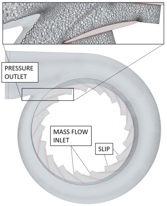
Figure 1.
Geometry domain, polyhedral mesh and boundary conditions used for optimization.
2.2. Optimization Algorithms
We compare the performance of three different approaches to optimize the volute downstream of a vaned diffusor. The two distinguishing features are whether a geometry parametrization is used (as in Opt1 and Opt3) and whether adjoint gradient information is exploited (as in Opt2 and Opt3). Note how we use gb and gf to abbreviate gradient-based and gradient-free, respectively. Similarly, pb and pf stands for parameter-based and parameter-free.
2.2.1. Opt1 gf-pb: Parameter-Based, Gradient-Free Optimization
The baseline geometry is used as the reference geometry for the parametrization: we take this geometry and distribute 26 points on the surface of the volute. Here, each of these points may be pushed and pulled in the x, y and z directions. This will morph the geometry on a CAD level such that the surrounding will be pulled along with the moving point. How this looks is visualized in Figure 2: First, we see how 26 points (brown dots) are placed on the surface of the model. Second, we see how pulling point 11 in an outward direction (red arrow) affects the volute. Note that the placement and number of these points affect both the design space and the best design within this design space. Apart from a designer’s experience, there is no way of knowing a priori which of the points will play an important role and which will not. However, adjoint gradients can help identify important parameters, as the next sections will demonstrate.
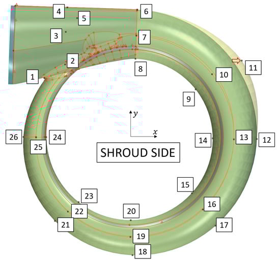
Figure 2.
Parametrization of volute geometry with 26 points or 78 degrees of freedom, respectively.
The optimization algorithm SHERPA (Simultaneous Hybrid Exploration that is Robust, Progressive and Adaptive) comes with the Siemens software package Simcenter HEEDS [15] as well as Simcenter Star-CCM+ DesignManager. Due to its commercial nature, the implementational details of the algorithm are hidden from the user and are, thus, a black box. According to the manual, SHERPA tests several local and global search strategies simultaneously as the design database grows, and it tunes the parameters of the search algorithm along the way to adjust to the nature of the design problem. The sole input the user gives is the number of designs that shall be evaluated, which is set to 500 in this study.
In terms of setting up the optimization, the following is the simplest of the three approaches: setting up the CFD model, defining the cost function and creating the parametrization are all that the user needs to start the process.
2.2.2. Opt2 gb-pf: Parameter-Free, Gradient-Based Optimization
For the second optimization algorithm, we test an algorithm that is gradient-based and works without an explicit parametrization of the volute. In contrast, the nodes of the mesh on the volute surface serve as parametrization. Nonetheless, we refer to this algorithm as parameter-free, as this parametrization is not something a designer defines explicitly. The algorithm is composed of four steps that are repeated iteratively:
Step 1: Calculate the primal solution;
Step 2: Calculate the adjoint solution and shape sensitivities;
Step 3: Apply Vertex Morphing to smooth shape sensitivities;
Step 4: Deform mesh by means of Steepest Descent.
Step 1: Primal CFD Simulation
First, the simulation needs to converge as close to machine precision as possible. This is an important prerequisite for the next step.
Step 2: Shape Sensitivities
Once again, we wish to minimize the pressure loss. Using the adjoint method we are able to calculate the sensitivity of this cost function with regard to each node of the mesh X. This is conducted using Star-CCM+, which uses a discrete adjoint approach to calculate mesh sensitivities. The most important aspects of this method are summarized here. For a more general introduction, the reader is referred to [16].
Three steps are necessary to evaluate the sensitivity :
- 1.
- The residuals of the primal problem have to be driven as close to machine precision as possible, i.e.,with representing the flow variables. Application of the chain rule to the state equation (Equation (1)) delivers
- 2.
- Second, the adjoint variables have to be evaluated, which are a counterpart to the state variables and defined as the solution of the linear systemwith being the sensitivity of the residual with regard to the flow field and representing the sensitivity of the cost function with regard to the flow. The total derivative of with regard to the mesh X is
- 3.
- Third, we wish to use the mesh sensitivity to determine how a change in the surface mesh affects the cost function ; that is, we want to find . Star-CCM+ provides a method for this purpose, which utilizes a spring analogy. The respective computation is cheap. For the studied volute, these surface sensitivities are visualized in Figure 3 for the baseline design. They tell us where we need to push and pull the volute geometry in order to minimize . These sensitivities serve as input for the Vertex Morphing algorithm, as described below.
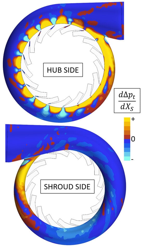 Figure 3. Surface sensitivity of cost function with regard to surface node position .
Step 3: Vertex Morphing
Vertex Morphing (VM) is introduced in [17]. VM uses control points . The discretization of the control field corresponds to the discretization of the design surface. Hence, no explicit parametrization is needed. Paramount to VM is that design updates are computed in a smooth control space. The relation between the control points in the control space and the nodes in the geometry space is defined as follows
where
with being the distance between and . M is the filter mapping and establishes a relation between neighboring nodes. R is the filter radius that defines the corresponding influence area and steers the length scale of the details of the design update. Applying this filter ensures that any control point update leads to a smooth update of the geometry.
The derivative of the geometry updates with regard to the control point updates is needed to drive the steepest descent algorithm:
Using this, the required design sensitivities of the cost function are computed as
Finally, the actual shape update is computed as
with being a scaling factor to control the step width of the steepest descent algorithm. Note that VM boils down to building the sparse matrix M and applying two matrix–vector multiplications. The procedure is implemented in Python (v3.9.7) using the SciPy library [18] (v1.7.3).
Using VM, no explicit parametrization must be introduced. Nevertheless, the design space is as large as possible for the given discretization, which maximizes the potential for improvements. The designer has to choose just one parameter, i.e., the filter radius R. For this study, R is about half of the diffusor vane length.
Step 4: Mesh Deformation
The calculated shape update is read back into Star-CCM+. The built-in mesh morphing functionality is applied to morph the mesh.
2.2.3. Opt3 gb-pb: Parameter-Based, Gradient-Based Optimization
Finally, the gradient- and parameter-based optimization approach is introduced. This algorithm exploits features from both Opt1 gf-pb and Opt2 gb-pf. The idea is to stick with the parametrization of Opt1 gf-pb and evaluate how each of these parameters affects the geometry. In other words, we wish to determine the sensitivity of the shape of our volute geometry with regard to the 26 points , i.e.,
One example of such a sensitivity is given. In Figure 2, we have already seen how a translation of point in the x-direction changes the geometry. The formalization of this as parameter sensitivity is visualized in Figure 4. This derivative is calculated by means of a second-order central differences approximation; that is, the geometry is varied by a small margin h, both in positive and negative directions, for each parameter . The difference between these two variations is then computed and divided by in order to approximate .
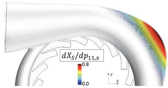
Figure 4.
Shape sensitivity with regard to x component of point 11.
By combining this information with the surface mesh sensitivity, as described in Equation (4),
we may, by means of the chain rule, determine the sensitivity of the cost function with respect to the parameter , i.e.,
This may seem like a complicated approach to determine , as this could also be performed easily by exploiting a finite differencing scheme. The great benefit lies in the simulation costs: Presume we would try to determine
using first-order finite differences; we would need to run at least 79 costly CFD simulations. On the other hand, exploiting Equation (12), we need one primal and one adjoint CFD simulation, as well as 78 parameter sensitivities, in which the latter operation is fairly cheap.
Apart from the previously cited study by [6], we are not aware of any further publications where this type of gradient calculation is used in conjunction with compressor volute optimization. However, in the context of multi- and single-disciplinary radial compressor and turbine wheel design, some more studies have since been published; see [19,20,21,22,23].
Finally, we need an algorithm that uses this gradient information to suggest the next design iteration. We apply a Sequential Quadratic Programming (SQP) algorithm provided by Siemens Simcenter. According to Siemens, the implementation follows that of [24]. The great benefit of SQP as compared to Steepest Descent is that SQP builds and continuously improves an approximation of the second derivative, i.e., the Hessian matrix, that is then exploited to steer the algorithm towards the optimum.
2.3. Optimization Results
The convergence is plotted in Figure 5. First, note that the x axis is logarithmic. This is performed to improve data presentation. Second, note that we only plot designs that are better than the previously best design. Hence, intermediate yet worse designs are omitted in this visualization.
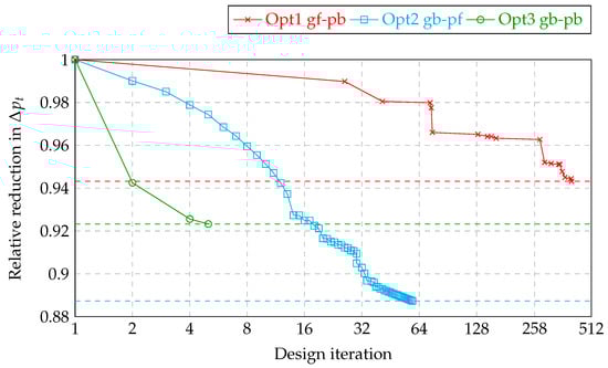
Figure 5.
Convergence plot of all three optimizations.
The parameter-based, gradient-free optimization (Opt1 gf-pb) is the slowest of the three. The 26th design is the first to actually reduce the pressure drop compared to the baseline. The 403rd design is the best that is found within the given limit of 500 evaluations. Design 403 reduces the pressure drop by 5.7%. As a matter of fact, this cannot be the global optimum within the given design space, as we will see later. Hence, granting the algorithm to do more evaluations might have led to further improvements.
The parameter-free, gradient-based algorithm (Opt2 gb-pf) proves to be the most successful in terms of pressure loss reduction as is reduced by a remarkable 11.3% for design 59. Closely studying Figure 5 reveals that design 30 is shown twice: the geometry has been remeshed after 30 iterations, and the optimization has been restarted from there. We stopped the algorithm at design 59, even though the algorithm clearly exhibits room for improvement. The problem lies in the applied steepest descent algorithm, which, at first, is very fast; however, it gets slower and slower from one step to the next. Hence, many additional design iterations need to be studied to improve the design by a small margin.
The parameter- and gradient-based approach (Opt3 gb-pb) is quite successful at first; however, it stalls after five iterations at a result that is still remarkably better than design 403 of Opt1 gf-pb, even though both algorithms share the same design space and parametrization, respectively. Why the algorithm stalls so soon is difficult to answer. We propose two hypotheses: (1) The algorithm may have hit a local or the global minimum. If this were true, however, one would expect , which is not the case, though. The derivative is reduced by only about one order of magnitude compared to the baseline design. (2) Hence, we deem it more likely that the derivative approximation is not precise enough for further improvements. This is not studied any further within this paper. Instead, we focus on the improvements the algorithms gained and aim to understand where they come from.
In Figure 6 the baseline as well as the three optimized volutes are shown side-by-side. In the next section particular attention is paid to Opt2 gb-pf and Opt3 gb-pb. In contrast, the result from Opt1 gf-pb is not discussed any further, as the results were too poor compared to the other two.
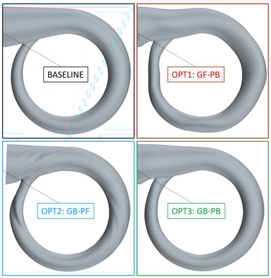
Figure 6.
All four volutes (side view).
Lastly, in Table 1, all three of the introduced optimization methods, their key features, as well as their results are summarized.

Table 1.
Overview of optimization schemes.
3. Effect on Compressor Performance
The focus lies on two interesting design changes in this section:
- Opt2 gb-pf introduces helical structures into the volute that follow the wake of the guide vanes.
- Both Opt2 gb-pf and Opt3 gb-pb substantially alter the tongue area, which greatly impacts the circumferential pressure distribution.
Before that we will discuss how the CFD setup has been enlarged to better understand the interaction between volute and guide vanes plus impeller.
3.1. Geometry and CFD Setup
For the sake of optimization, the CFD setup had been reduced to a bare minimum. When it comes to studying how Opt2 gb-pf and Opt3 gb-pb affect the flow, we intend to additionally look at this in a context where the entire guide vane, as well as the impeller, is modeled. The respective mesh is shown in Figure 7. The model has 6.9 million cells in total, and the boundary layer is resolved with . We use a stagnation inlet and mass flow outlet. An implicit mixing plane is used between the stationary and rotating reference frames.
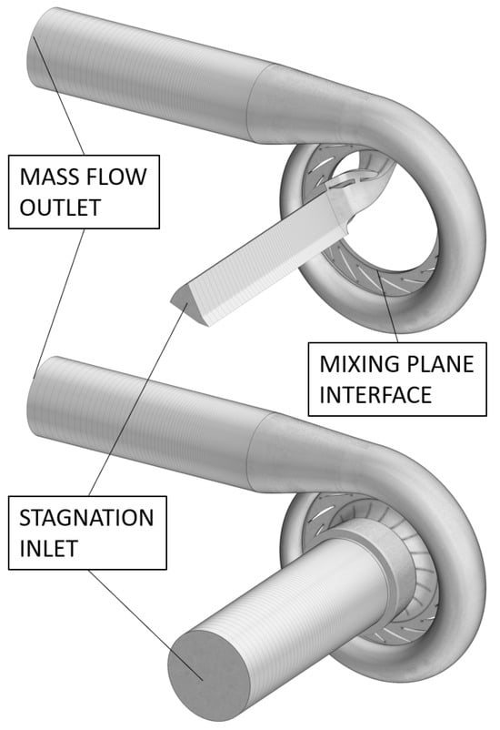
Figure 7.
Stationary CFD model including impeller segment, guide vanes and volute (top), as well as unsteady CFD model including full impeller, guide vanes and volute (bottom).
As the name suggests, mixing planes mix out flow quantities. To make sure that this mixing did not prevent us from drawing the right conclusions with regard to the volute geometries and their effect on the flow, we additionally ran transient simulations. The mesh settings are kept the same. However, the entire impeller is meshed, not just a segment. Thus, we have 12.8 million cells in this setup; see Figure 7. The impeller rotates 24 times with a coarse time step (40 steps per pitch) and a coarse mesh. Then, it rotates another 10 times with a finer time step (100 steps per pitch) on the final mesh. A second-order temporal discretization is applied.
In summary, three different CFD setups have been used for this study as presented here.
CFD-light has been used throughout the optimization process; see Figure 1. No impeller was modeled here.
CFD-steady is the steady-state setup shown in Figure 7 (top) using a mixing plane between the impeller and guide vanes.
CFD-unsteady is the very costly setup shown in Figure 7 (bottom) used to make sure that the mixing plane does not prevent the right conclusions.
Measurement data exist for the compressor with a baseline volute. At the studied operating point, CFD-steady underpredicts the pressure ratio by and the efficiency by . CFD-unsteady underpredicts the pressure ratio by and the efficiency by .
3.2. Helical Dents
One great aspect of the parameter-free approach Opt2 gb-pf is that its results are not limited to a parametrization imagined by a designer. Hence, it may create surprising results. In Figure 3 we have seen the surface sensitivity resulting from the adjoint calculation. This figure already hints at structures that are particular to vaned diffusors. And indeed, such structures are visible on the optimized volute. In the wake of most vanes, we find helical structures on the volute that make it look like a wrung towel. In Figure 8 some of these helical dents can be seen. It is difficult to visualize how these dents interact with the flow. We chose to use the wall shear stress. It shows where we have jet flow (red) and where we have wake flow (blue to green). As can be seen in Figure 8, the flow path is dented in the jet area. Hence, these dents presumably help redistribute the flow. Centrifugal force pushes the jet radially outward into the dent and then to the side into the wake area, thus making better use of the available cross sectional area.
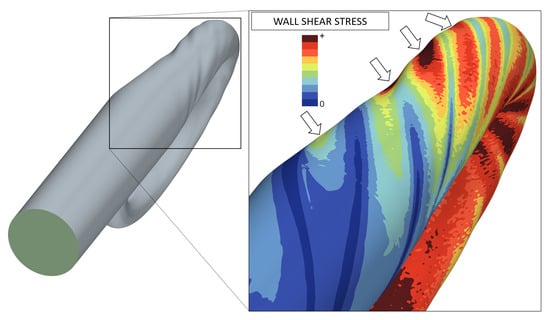
Figure 8.
Wall shear stress illustrating how geometry is adapted to guide vane wakes.
In case one were to avoid these small scale changes to the geometry and nevertheless were to use this gradient-based, parameter-free optimization approach, there is an easy fix: increasing the filter radius R used in the smoothing operation called Vertex Morphing from Equations (5)–(9) would eventually lead to large-scale shape updates.
3.3. Tongue
Noticeably, all optimizations resulted in geometries where the distance between the tongue and the radial vaned diffusor outlet has been increased compared to the baseline. Given as the ratio of the tongue diameter over the diffusor outlet diameter, i.e., , the baseline design has the ratio , whereas, after optimization, we find
- The ratio for Opt2 gb-pf;
- The ratio for Opt3 gb-pb.
Additionally, there is a slight circumferential shift of the tongue in a clockwise direction. This is indicated in Figure 6 by the dotted black line that shows the position of the tongue in the baseline design. Looking once more at the surface sensitivities visualized in Figure 3, we find that these large design changes around the tongue were expected, as this is the area where the sensitivities peaked. These design changes will affect the ratio at the respective cross sections. Hence, we study the cross section A, the radius (Note that the letter R is used twice in this paper. It is also used for the filter width of the Vertex Morphing algorithm). R of the center of gravity of this area, as well as the mass flow at several cuts. The positions of these evaluation planes are shown in Figure 9. Apart from the plane at , all planes are oriented radially. The plane at is oriented to better match the main flow direction, which also affects the calculation of R: The radius R is supposed to represent the perpendicular lever of flow with regard to the rotation axis. Thus, for the plane , it is not simply the distance between the center of gravity of A and the rotation axis.
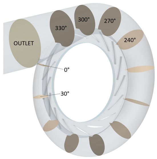
Figure 9.
Cross sections at which area , , radius and mass flow are evaluated.
For all 12 planes the area-to-radius ratio , the area , the radius and are shown in Figure 10. Note that we used the baseline’s area-to-radius ratio at , the outlet area , the perpendicular outlet radius and the outlet mass flow for normalization, which are equal and constant for all geometries and CFD setups. First we notice that the radii R are almost constant and hardly change throughout optimization. However, both optimizations drastically changed the cross sectional area A and, with that, the ratio: For the positions ranging from to , the area and were increased by both optimizers. For angles above the area and actually decreased. This becomes even more interesting in light of the mass flow distribution. First of all we notice that the mass flow passing through the plane at is about 20% higher than the actual exit mass flow , highlighting that a considerable amount of mass completes more than a full circle around the volute before actually leaving through the exit. Additionally, we find that the optimizers even increased this effect; that is, the mass that is doing an extra round is raised. In other words, as the cross section at was lowered and the mass was raised, the axial velocity increased.
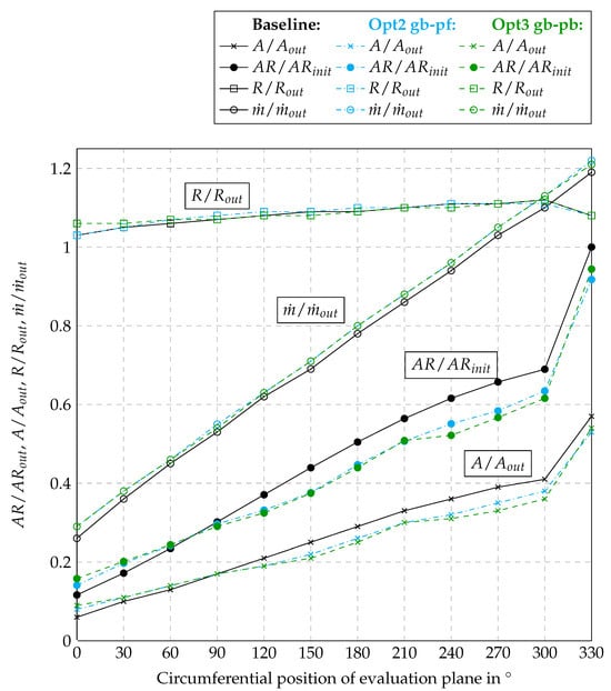
Figure 10.
Area-to-radius ratio , area , radius and mass flow versus circumferential position.
Interestingly, one may narrow down where the mass flow comes from that does not leave the volute right away; see the streamline plot in Figure 11. We have numbered the channels in between two guide vanes and spawned differently colored streamlines within channels 1, 10, 11 and 14. The figure shows the volute from Opt2 gb-pf with the simulation setup CFD-steady. We notice that it is mainly the channels that approximately oppose the tongue—10 (pink) and 11 (yellow)—whose streamlines do an extra round: The pink and yellow streamlines take approximately for their screw motion around the volute just to ‘miss’ the volute’s exit. This appears to be beneficial even though the longer flow path of these streamlines calls for higher pressure losses. Otherwise, the optimizers would not have strengthened this behavior by moving the tongue away from the guide vanes and increasing the cross sectional area, thus raising the question of why this may be advantageous.
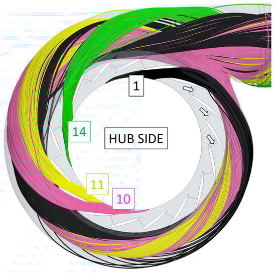
Figure 11.
Streamlines showing that the flow coming in through channels 10 (pink) and 11 (yellow) does not leave the volute on the shortest route.
We better understand this behavior by looking at the pressure distribution. For this purpose, we once more use the numbering of the channels from 1 to 17, which was previously introduced. Within each channel, we evaluate the static pressure before and after optimization at the cross sections highlighted by the white arrows in Figure 11. We do this evaluation for CFD-light and CFD-steady to highlight that these findings are not particular to a certain setup. We study both the mass flow through each channel as well as the static pressure. The data are summarized in Figure 12.
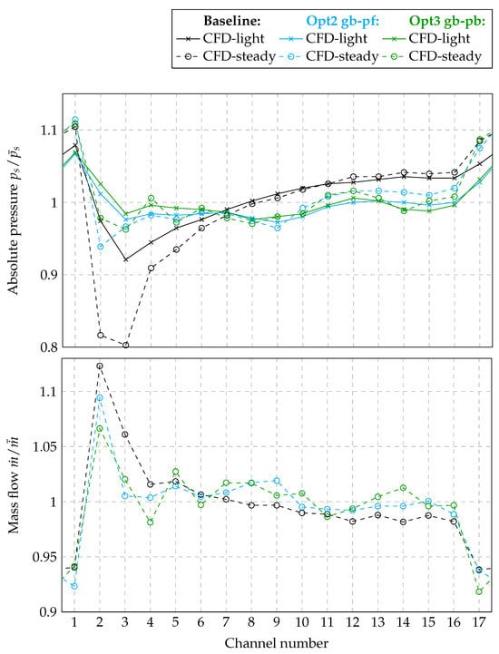
Figure 12.
and versus channel.
First, we notice that the mass flow per channel, normalized by the average mass flow , may not be considered constant. On the contrary, we find that channels 1 and 17 have the lowest mass flow, and channel 2 has the highest mass flow. This holds true for three different volutes. Hence, this contradicts a central assumption we made throughout the optimizations. It is noteworthy, however, that the optimized geometries reduce the variance significantly.
Second, we focus on the static pressure , normalized by the average of the presented data and visualized in the same figure. Here, we see, for the baseline volute, that the static pressure has its minimum around channels 2 and 3 and grows continuously to its maximum at channel 1. Shifting our focus to the volutes designed by the optimizers, we find that by trying to minimize pressure losses, both optimizers apparently succeed at equalizing the static pressure for all the channels. Presumably, this equalization is enabled by two changes: First, the tongue’s influence is reduced, as it was pushed away a little from the impeller, which appears to be raising the static pressure. Second, the reduction in the cross sections above and the corresponding velocity increase lead to a reduction in static pressure. These observations prove independent of whether we look at CFD-light or CFD-steady; however, the extent to which this finding is observed varies from setup to setup.
3.4. Volute Performance in Different CFD Setups
Lastly, we compare the volute and compressor performance in terms of pressure loss and efficiency, respectively. The results are summarized in Table 2. It has to be read as follows: The in the column CFD-light represents the reduction in pressure loss we achieved as compared to the baseline geometry. An evaluation of efficiency is not possible, as CFD-light did not include an impeller. The in the column CFD-steady and CFD-unsteady represents how much the pressure at the volute outlet has increased for the given operating point. For CFD-steady and CFD-unsteady we may also evaluate a change in total-to-total efficiency , which is given in the same table. For the unsteady simulation, stagnation temperatures and pressures have been time-averaged for the final rotation before the efficiency has been evaluated.
Table 2.
Volute performance in different setups.
First, we note that the optimizations bear fruit. Total pressure at the outlet and efficiency have increased. Peculiarly, the data show two ‘anomalies’.
- In CFD-steady, the volute Opt3: gb-pb performs best. Based on the optimization results, we expected Opt2: gb-pf to be the best. Our hypothesis is that this is a consequence of the two simulation setups (CFD-steady and CFD-light) being too different in terms of mesh resolution and mass flow distribution, which apparently prohibits the transferability of the results.
- In CFD-unsteady, the volute Opt3: gb-pb performs best in terms of total pressure at the outlet, and the volute Opt2: gb-pf performs best in terms of efficiency; that is, Opt2: gb-pf shows lower temperatures at the outlet . Hence, the impeller works more efficiently in the latter setup.
4. Summary
Three different optimization strategies have been tested with varying success on the same design problem; that is, a reduction in pressure loss within a volute downstream of a vaned diffusor.
The parameter-based, gradient-free optimization approach (Opt1: gf-pb) has proven slow compared to the other two approaches. Clearly, this is the curse of dimensionality; that is, the optimizer struggles with the size of the design space and, thus, needs many evaluations. In contrast, both gradient-based approaches yielded a relevant improvement with very little simulation time.
The optimization setup was cost optimized; that is, we tried to use few cells. Given the speed of gradient-based optimizers, we believe it is a worthwhile investment of simulation time to study the CFD-steady setup more rigorously throughout the optimization phase. Hence, we intend to enlarge the setup step by step—first in terms of a mesh refinement and second in the form of including an impeller and connecting it via a mixing plane.
The parameter-free optimization Opt2 gb-pf proved very useful in that it helps reveal where and how the geometry might be altered for improvement. The ‘wrung towel’ we found would not have been attained with classical parametrization. Unfortunately, Opt2 gb-pf has not been a clear outperformer in the simulation setups with the impeller. This does not negate its benefits, though. Instead it hints at the need for an improved optimization simulation setup.
The equalization of static pressure in the circumferential direction appears to be tightly linked with the effort of reducing pressure losses. This has happened through a tilt of higher ratios at lower angles and vice versa. In that process, the tongue has moved away from the impeller, allowing for more mass flow to complete an extra round before exiting the volute.
Next, we plan to study some more aspects:
- The gradient-based work flows are fast and, thus, well-suited to find the best clocking position of guide vanes compared to the tongue.
- The equalization of pressures might have an effect on low-engine-order blade excitation that one may study by means of harmonic balance simulations.
- The design space may be increased even further to incorporate the guide vanes’ shape, position and angle into the setup.
- Finally, a back-to-back measurement is necessary to fully confirm the success of our optimization efforts. Furthermore, it will reveal whether the design changes affect compressor stability and, with that, surge margin.
Author Contributions
Conceptualization, N.L.; methodology, N.L.; resources, T.M.; writing—original draft preparation, N.L.; writing—review and editing, N.L., F.F. and T.M.; visualization, N.L.; supervision, T.M. All authors have read and agreed to the published version of the manuscript.
Funding
This research received no external funding.
Data Availability Statement
Dataset available on request from the authors.
Acknowledgments
We thank Rolls-Royce Power Systems AG for the permission to publish this paper.
Conflicts of Interest
All authors were employed by the company Rolls-Royce Solutions GmbH, and the authors declare no conflict of interest.
Nomenclature
The following nomenclature is used in this manuscript:
| Acronyms: | |
| A/R | Area-to-radius ratio |
| CFD | Computational fluid dynamics |
| SHERPA | Simultaneous exploration that is robust, progressive, and adaptive |
| SQP | Sequential quadratic programming |
| VM | Vertex morphing |
| Subscripts: | |
| Inlet | |
| Outlet | |
| Reduced | |
| s | Static |
| t | Total |
| Latin: | |
| A | Area |
| Mass flow | |
| R | Radius, filter width |
| Residual | |
| 298 | |
| T | Temperature |
| u | Circumferential speed |
| X | Mesh |
| Surface mesh | |
| Dimensionless wall distance |
References
- Casey, M.; Robinson, C. Radial Flow Turbocompressors; Cambridge University Press: Cambridge, UK, 2021. [Google Scholar]
- Ratz, J. Simultane Optimierung von Impeller, Beschaufeltem Diffusor und Volute hinsichtlich des Wirkungsgrads und des Pumpgrenzabstands; Forschungsberichte aus dem Institut für Gasturbinen, Luft-und Raumfahrtantriebe; Shaker Verlag: Düren, Germany, 2024; Volume 22. [Google Scholar]
- Heinrich, M.; Schwarze, R. Genetic Algorithm Optimization of the Volute Shape of a Centrifugal Compressor. Int. J. Rotating Mach. 2016, 2016, 13. [Google Scholar] [CrossRef]
- Peter, J. Numerische Untersuchung und Optimierung des Laufrades einer Pkw-Abgasturboladerturbine. Ph.D. Dissertation, Leibniz Universität Hannover, Hannover, Germany, 2016. [Google Scholar]
- Arifin, M.; Fudholi, A.; Wahyudie, A.; Vogt, D.M. Surrogate-based optimization of multiple-splitters radial compressor for solar hybrid microturbine. Energy Convers. Manag. X 2022, 16, 100332. [Google Scholar] [CrossRef]
- Hottois, R.; Châtel, A.; Verstraete, T. Adjoint-Based Design Optimization of a Volute for a Radial Compressor. Int. J. Turbomach. Propuls. Power 2023, 8, 41. [Google Scholar] [CrossRef]
- Lachenmaier, N.; Baumgärtner, D.; Schiffer, H.P.; Kech, J. Gradient-based optimization of a radial turbine volute and a downstream bend using vertex morphing. In Proceedings of the Turbo Expo: Power for Land, Sea, and Air, Virtual, 21–25 September 2020. Number GT2020-14145. [Google Scholar]
- Del Rio, A.; Casartelli, E.; Fleischli, B.; Mangani, L. New Concept for Design in Turbomachinery Applications Using Full RANS Gradient Methodology. J. Turbomach. 2022, 145, 041009. [Google Scholar] [CrossRef]
- Ji, C.; Wang, Y.; Yao, L. Numerical Analysis and Optimization of the Volute in a Centrifugal Compressor. In Proceedings of the Challenges of Power Engineering and Environment; Cen, K., Chi, Y., Wang, F., Eds.; Springer: Berlin/Heidelberg, Germany, 2007; pp. 1352–1356. [Google Scholar]
- Hazby, H.; O’Donoghue, R.; Robinson, C. Design and Modelling of Circular Volutes for Centrifugal Compressors. In Proceedings of the 14th International Conference on Turbochargers and Turbocharging, London, UK, 11–12 May 2021; CRC Press: Boca Raton, FL, USA, 2020. [Google Scholar]
- Ceyrowsky, T.; Hildebrandt, A.; Heinrich, M.; Schwarze, R. Reassessment of the Conventional: Numerical Validation of a 1D Model for the Prediction of Volute Losses. In Proceedings of the ASME Turbo Expo 2024: Turbomachinery Technical Conference and Exposition, London, UK, 24–28 June 2024. [Google Scholar]
- Lachenmaier, N.; Fröehlig, F.; Männle, T. Optimization of a Volute downstream of a Vaned Radial Compressor. In Proceedings of the 16th European Conference on Turbomachinery Fluid dynamics & Thermodynamics, Hannover, Germany, 24–28 March 2025; paper n. ETC2025-331. Available online: https://www.euroturbo.eu/publications/conference-proceedings-repository/ (accessed on 30 August 2025).
- Menter, F.R. Two-equation eddy-viscosity turbulence models for engineering applications. AIAA J. 1994, 32, 8. [Google Scholar] [CrossRef]
- Simcenter Star-CCM+. Available online: https://www.plm.automation.siemens.com/global/de/products/simcenter/STAR-CCM.html (accessed on 1 September 2022).
- Simcenter HEEDS. Available online: https://plm.sw.siemens.com/de-DE/simcenter/integration-solutions/heeds/ (accessed on 23 August 2024).
- Peter, J.E.; Dwight, R.P. Numerical sensitivity analysis for aerodynamic optimization: A survey of approaches. Comput. Fluids 2010, 39, 373–391. [Google Scholar] [CrossRef]
- Bletzinger, K.U. A consistent frame for sensitivity filtering and the vertex assigned morphing of optimal shape. Struct. Multidiscip. Optim. 2014, 49, 873–895. [Google Scholar] [CrossRef]
- Jones, E.; Oliphant, T.; Peterson, P. SciPy: Open Source Scientific Tools for Python, 2001–2025. Available online: http://www.scipy.org/ (accessed on 30 August 2025).
- Lachenmaier, N. Multidisciplinary Gradient-Based Optimization of Radial Turbines; Forschungsberichte aus dem Institut für Gasturbinen, Luft- und Raumfahrtantriebe; Shaker Verlag: Düren, Germany, 2023; Volume 20. [Google Scholar]
- Schwalbach, M.; Verstraete, T.; Müller, L.; Gauger, N. CAD-based adjoint multidisciplinary optimization of a radial turbine under structural constraints. In Proceedings of the GPPS, Montreal, QB, Canada, 7–9 May 2018. [Google Scholar]
- Taniguchi, N.; Kanzake, T.; Verstraete, T. Parametric Optimization of Centrifugal Compressor using adjoint Method. In Proceedings of the Aufladetechnische Konferenz, Dresden, Germany, 26–27 September 2023. [Google Scholar]
- Lucian, H.; Fleischli, B.; Casartelli, E.; Mangani, L.; Lehr, A.; Weickgenannt, A. Adjoint Optimization of Real Gas Centrifugal Compressor. In Proceedings of the 15th European Conference on Turbomachinery Fluid dynamics & Thermodynamics, Budapest, Hungary, 24–28 April 2023. [Google Scholar] [CrossRef]
- Chatel, A.; Verstraete, T. Multidisciplinary optimization of the SRV2-O radial compressor using an adjoint-based approach. Struct. Multidiscip. Optim. 2023, 66, 112. [Google Scholar] [CrossRef]
- Schittkowski, K. NLPQLP: A Fortran Implementation of a Sequential Quadratic Programming Algorithm with Distributed and Non-Monotone Line Search—User’s Guide, Version 3.0. 2006. Available online: https://www.researchgate.net/publication/238690491_NLPQLP_A_Fortran_Implementation_of_a_Sequential_Quadratic_Programming_Algorithm_with_Distributed_and_Non-Monotone_Line_Search_-_User%27s_Guide_Version_30 (accessed on 30 August 2025).
Disclaimer/Publisher’s Note: The statements, opinions and data contained in all publications are solely those of the individual author(s) and contributor(s) and not of MDPI and/or the editor(s). MDPI and/or the editor(s) disclaim responsibility for any injury to people or property resulting from any ideas, methods, instructions or products referred to in the content. |
© 2025 by the authors. Published by MDPI on behalf of the EUROTURBO. Licensee MDPI, Basel, Switzerland. This article is an open access article distributed under the terms and conditions of the Creative Commons Attribution (CC BY-NC-ND) license (https://creativecommons.org/licenses/by-nc-nd/4.0/).