
Article

The Effect of the Purge–Mainstream Density Ratio on Rim Seal Fluid Mechanics †

Department of Mechanical Engineering, University of Bath, Bath BA2 6JY, UK
*
Author to whom correspondence should be addressed.
This manuscript is an extended version of the ETC16-210 paper published in the Proceedings of the 16th European Turbomachinery Conference, Hannover, Germany, 24–28 March 2025.
Int. J. Turbomach. Propuls. Power 2025, 10(4), 46; https://doi.org/10.3390/ijtpp10040046
Submission received: 20 June 2025 / Revised: 15 July 2025 / Accepted: 21 July 2025 / Published: 21 November 2025

Abstract

Significant density ratios arise in a gas turbine due to severe temperature gradients between the hot mainstream gases leaving the combustor and the superposed purge flow injected from the secondary air system. Engineers seek to minimise the ingestion of hot annulus gas through the rim seal at the periphery of the turbine wheel-space to maximise component life while continuing to increase the turbine entry temperature in pursuit of optimised thermodynamic cycle efficiency. The majority of experimental ingestion facilities assess sealing performance at a near-unity purge–mainstream density ratio which negates the impact of this significant contributor to ingestion. This study investigates the impact of the density ratio on the fluid mechanics across the rim seal of a single-stage turbine facility. The results demonstrate that the purge–mainstream density ratio is a crucial consideration when designing the rim seal architecture, particularly with the transition to alternative fuels which have the potential to augment the temperature gradient. A density-affected region at the intermediate superposed purge flows is identified where the non-unity density ratio has the greatest impact on outer cavity swirl and sealing effectiveness. Furthermore, unsteady pressure spectra in this region exhibit a suppression of the low-frequency spectral band as the density ratio is increased, highlighting a causal link between unsteadiness and ingress.

1. Introduction

Gas turbine cycle efficiency is dependent on turbine entry temperature (TET), a fact that is equally relevant to conventional, synthetic and alternate fuels. As technology advances and TETs rise in accordance, the life-limiting effect of hot gas ingestion, which penetrates turbine wheel-spaces and therefore demands an effective cooling system, poses an increasingly critical challenge for the engine designer. Superposed purge air is employed to seal the turbine wheel-space at the cost of aerodynamic and thermal efficiency; and rim seals are installed at a high radius to limit the cooling air required. The purge–mainstream density ratio arises due to the extreme temperature difference between the flow exiting the combustor and the cooling air, bled from the compressor. State-of-the-art gas turbines are subjected to a density ratio of D R 1.5 [1], which is expected to increase to D R = 2 or beyond with advancements in sustainable fuelling and improved combustion technologies [2].
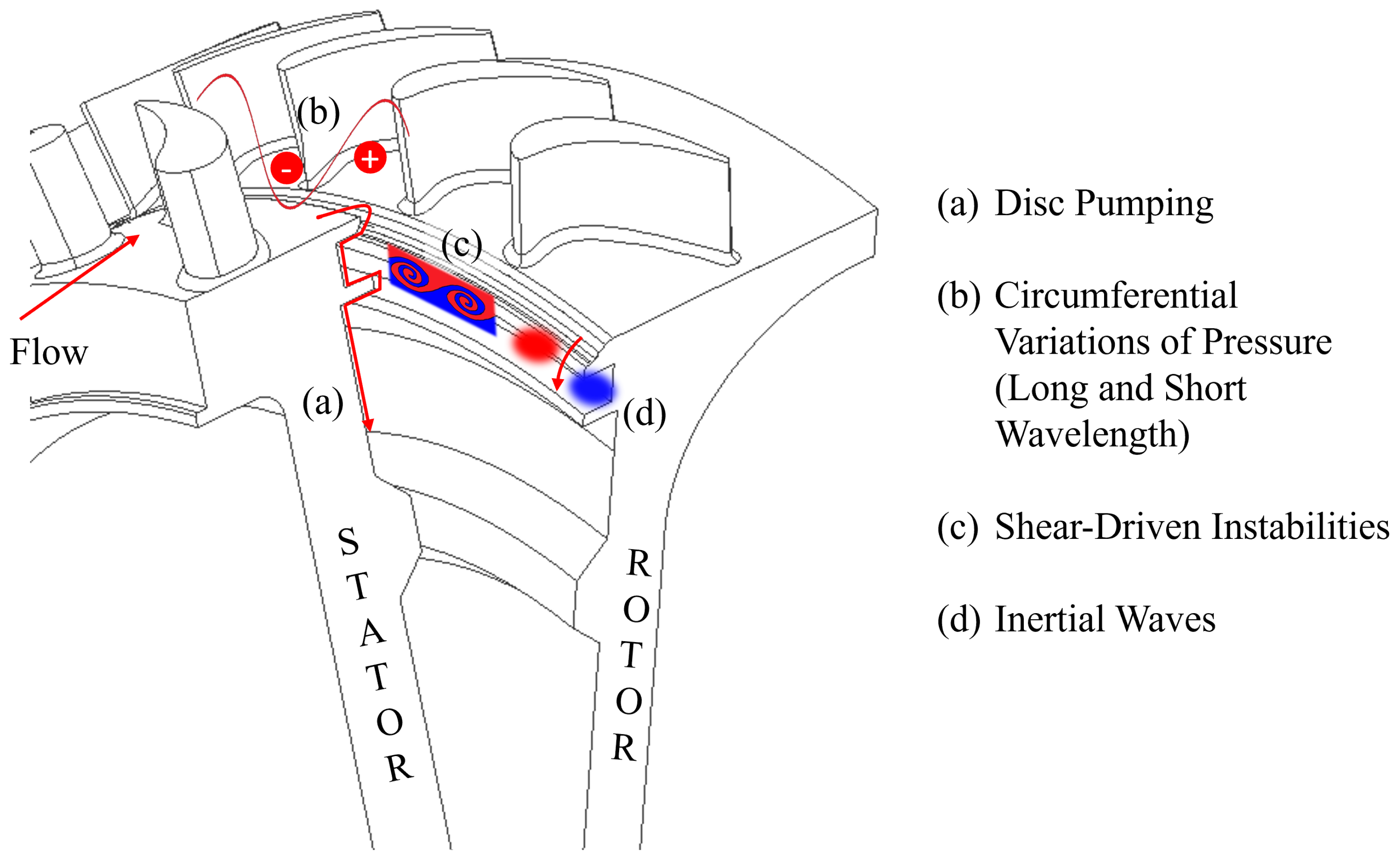
Figure 1 details the contributing mechanisms for ingress, highlighting the established drivers proposed in the literature. In the interest of brevity, the reader is referred to the work of Chew et al. [3] for a detailed discussion of the fluid dynamic mechanisms. Vella et al. [4] identify the principal driver as the purge–mainstream swirl gradient, denoted by (c) in Figure 1. The effect of the purge–mainstream density ratio on ingress (and its contributing drivers) is seldom considered in the literature, and the effect of the density ratio on the unsteadiness inherent in the ingestion phenomena is absent from the literature.
Ingress research typically employs a near-unity density ratio across the rim seal, arising from the injection of a tracer gas at isothermal conditions. Therefore, the impact of an engine-relevant purge–mainstream density ratio is neglected. Foreign gas injection can be introduced to simulate an enhanced density ratio while the test facility remains at ambient conditions. This practice is commonplace in film cooling, where different density ratios have a significant impact on the cooling performance [5]. If turbulent mixing and large-scale structures are expected to dominate in an incompressible flow regime, the governing momentum equation would be independent of gas species. Hence, engine-representative velocity and density boundary conditions can be simulated without artificially raising the flow temperature. However, the governing enthalpy equations will diverge with increasing amounts of foreign gas due to differences in specific heat; thus, parameters which are independent of the thermal boundary conditions should be the focus of foreign gas experiments [5].
This study considers the impact of the purge–mainstream density ratio on rim seal fluid mechanics. Measurements of time-averaged and time-resolved pressure, swirl and sealing effectiveness are acquired in a turbine rotor–stator wheel-space. The relative effect of the density ratio is characterised and a robust causal relationship between unsteadiness and ingestion is demonstrated over a range of density ratios. This paper is an extension of the work originally presented by [6] at the 16th European Turbomachinery Conference.

Studies of Ingress with Non-Unity Density Ratios

Johnson and Daniels [7] were the first to present measurements of sealing effectiveness with raised purge density. In their experiment, air and CO 2 were combined and injected as purge air, with sealing effectiveness determined from concentration measurements acquired on both the stator and rotor discs. The study concluded that the concentration of CO 2 on the rotor was near 100% across the radial extent of the rotor disc for conditions where the purge flow rate exceeded the boundary layer entrainment limit. The study also concluded that there is a strong link between the purge–mainstream density ratio and the distribution of the sealing flow in the wheel-space. A 50% increase in the density of the purge relative to the annulus led to a decrease in sealing effectiveness of 1 to 15% for both comparable mass and volume flow rates.
Orsini et al. [8] conducted an experimental campaign using nitrogen and CO 2 as alternate coolants which allowed the authors to employ a pressure-sensitive paint (PSP) technique to measure the effectiveness on both the stator and rotor discs. The data were presented in terms of a modified version of the Φ 0 parameter that included the density ratio, defined as follows:
Φ F i = Φ 0 · ρ 0 ρ a .
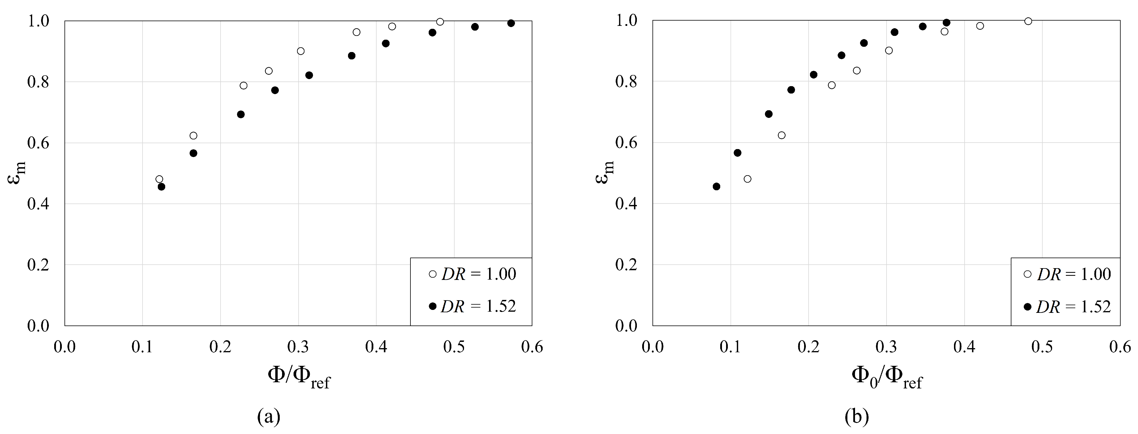
When considering this definition for Φ F i and a mass-based approach to sealing effectiveness, the plot in Figure 2a was obtained by Orsini et al. [8] at a flow coefficient of 0.32. When the data are subsequently converted to the original definition of Φ 0 by manipulation of Equation (1), the results can be re-plotted as in Figure 2b using the density ratio stated in the manuscript.
The apparent trend reversal in Figure 2b highlights the importance of a universal sealing parameter, which is a function of the purge density.
Tang et al. [9] established a theoretical framework for predicting the effect of a non-unity density ratio. It was demonstrated that, when buoyancy effects are negligible (demonstrated to be the case at engine operating conditions), the ingress mass flow rate is proportional to the square root of the product of the densities of the ingress and egress.

2. Methodology

2.1. Experimental Facility

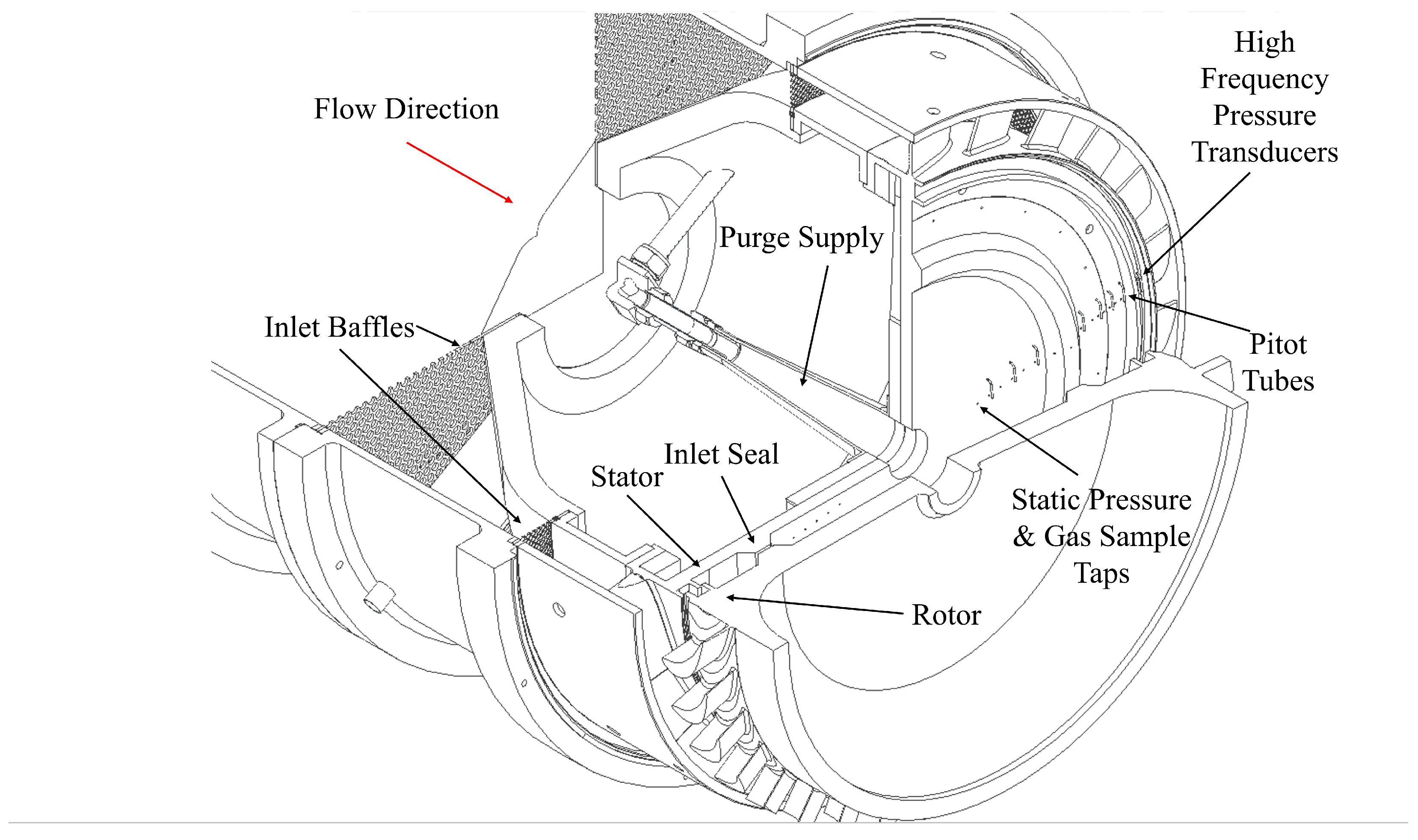
The experimental campaign employed the Large Annulus Rig at the University of Bath, a single-stage, high-pressure turbine with independent control of the superposed purge flow density. A detailed account of the facility’s design is presented in the work of Jones et al. [10] and therefore only a brief summary of the technical specification is included here. A section view of the facility is shown in Figure 3 illustrating the geometry of the wheel-space and salient instrumentation. The operating conditions used in this campaign are given in Table 1.
Purge flow was introduced through the bore of the stator as a mixture of air and CO 2 to achieve independently controlled density ratios (DR) relative to the annulus. Air was fed from an isolated buffer tank and CO 2 supplied from a cryogenic manifold; complete mixing takes place upstream of the inlet to the wheel-space, yielding an isotropic blend [10]. For this campaign, blends of 1%, 10%, 50% and 100% CO 2 by volume (corresponding to DR = 1.00, 1.05, 1.26 and 1.54) were used to investigate the effect of the purge–mainstream density ratio on the fluid mechanics of the rim seal flows.

2.2. Instrumentation

Measurements of static pressure and CO 2 concentration by volume were acquired from hypodermic ports on the stator wall. Further to these, Pitot tubes were installed at x/S = 0.19 and aligned with static taps on the wall to permit the calculation of the tangential component of velocity (or swirl ratio, β ) according to Equation (2):
β = U θ Ω r = 2 ( p T p ρ ) Ω r
Pressure in the turbine annulus and purge supply was measured using a Mouser 5PSI-D-PRIME-MV differential pressure transducer (Mouser, London, UK) and acquired through a SIERRA Instruments CADET V14 system. Pressure ports in the wheel-space were multiplexed through a rotary Scanivalve (Scanivalve, Andover, UK) and exposed to an Applied Measurements PR3202 series differential pressure transducer (Applied Measurements, Reading, UK). All pressures were measured relative to the local pressure at entry to the outer wheel-space, measured at the inlet seal at r/b = 0.661 (location highlighted in Figure 3). Measurements of concentration were acquired through a Signal Group 9120MG multi-gas analyser (Signal Group, Camberley, UK) and similarly multiplexed through a solenoid array connected to twenty ports on the stator wall. Measurements of unsteady pressure were sampled at 200 kHz per sensor, processed using a DEWESoft-43A data acquisition system (Dewesoft, Haynes, UK) and obtained using Kulite XCQ-062 absolute pressure transducers (Kulite, Basingstoke, UK) installed at r/b = 0.983 to capture the rim seal instabilities. The main flow was maintained at ~28 °C by a dual-line water-cooled heat exchanger. K-type thermocouples were used to measure the temperature of the annulus at the exit of the heat exchanger, and of the superposed flow just prior to the flow entering the rig. An uncertainty analysis of the equipment used is conducted in Appendix A.

2.3. Salient Parameters

The local density of the fluid in the cavity is assumed to be statistically isotropic when considering a unity purge–mainstream density ratio. However, when considering a non-isopycnic volume, it is imperative that the density be resolved locally for all cases when ε < 1 . This is particularly important when resolving local components of velocity; the non-unity purge–mainstream density ratio also demands a volumetric approach to assessment of local species concentration.
The volumetric concentrations of CO 2 and air are defined in Equations (3) and (4), respectively:
c C O 2 = V C O 2 V C O 2 + V a i r = c ,
c a i r = V a i r V C O 2 + V a i r = 1 c .
By considering the volumetric ratio of CO 2 and air, it can be reasoned that
c 1 c = V C O 2 V a i r = n C O 2 n a i r ,
where n is the number of moles of each gas. This can be realised because of Avogadro’s Law, which states that, for any gas at a given temperature and pressure, the volume occupied by the gas will be the same if the molar content is conserved.
The average molar mass of the mixture at a given sampling location is calculated using
M m i x = n C O 2 M C O 2 + n a i r M a i r n C O 2 + n a i r .
By considering a single mole of air, Equation (5) can be substituted into Equation (6) to give
M m i x = c 1 c M C O 2 + M a i r c 1 c + 1 .
Algebraic manipulation of Equation (7) then yields
M m i x = c M C O 2 + ( 1 c ) M a i r .
Assuming that the mixture then exhibits ideal gas behaviour, the density of the mixture is as follows:
ρ = p M m i x R u T .
The local density, ρ , is employed in the calculation of the swirl ratio (Equation (2)); however, parameters relating to the superposed purge flow utilise ρ 0 , the density based on the flow parameters in the purge stream, to ensure consistent reference conditions. The pressure coefficient, C p , and dimensionless purge flow rate, Φ 0 , are therefore defined as follows:
C p = p p r e f 1 2 ρ 0 Ω 2 b 2
Φ 0 = m ˙ 0 2 π s c ρ 0 Ω b 2 = U Ω b
where p r e f is the reference pressure at the inlet seal and p T is the corresponding total pressure.
The volume and mass-based sealing effectiveness are defined as follows:
ε c = c s c a c 0 c a
ε m = c s * c a * c 0 * c a *
where the measurement port is denoted by subscript s, the annulus by subscript a and the superposed flow by subscript 0. * denotes a mass-based concentration of CO 2 . It should be noted that the two definitions of effectiveness are mathematically interchangeable using the method presented in [10].

3. Effect of Density on Rim Seal Fluid Mechanics

In this section, measurements of steady and unsteady pressure, swirl and species concentration are analysed to ascertain the effect of density on hot gas ingestion.

3.1. Pressure and Swirl

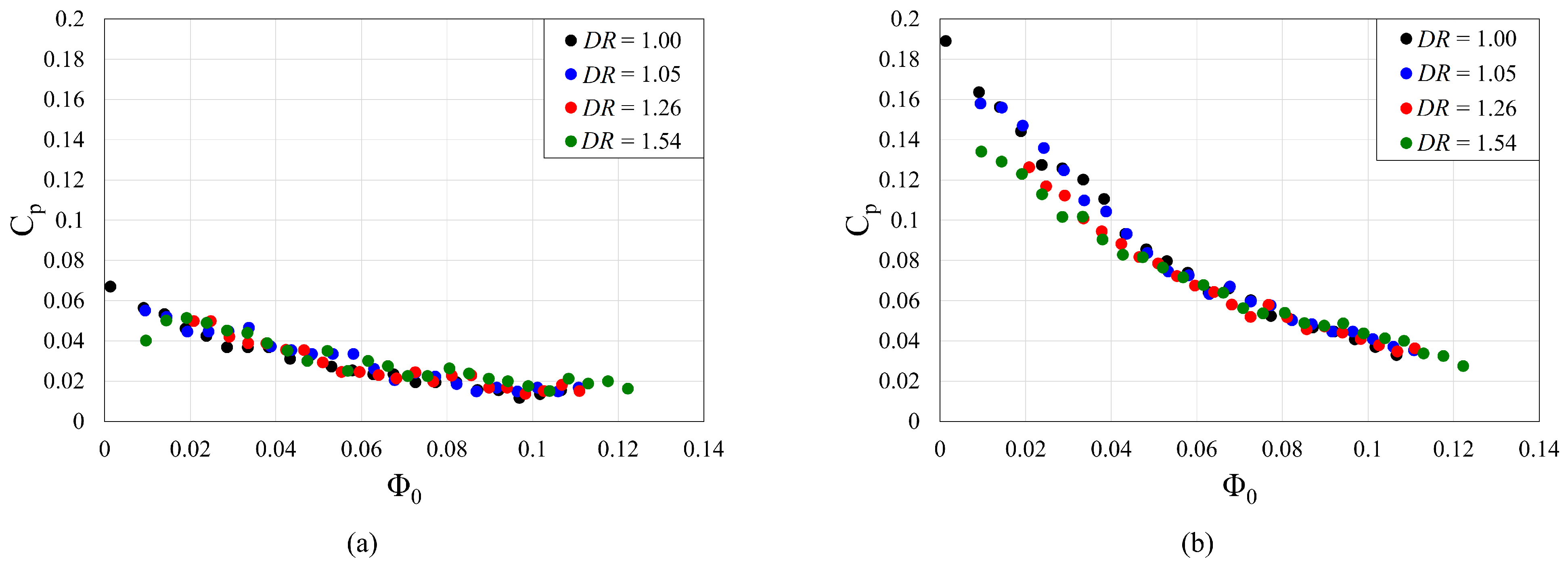
Firstly, the wheel-space flow structure is characterised through measurements of static pressure at two radial locations on the stator wall: one in the inner wheel-space and one in the outer wheel-space. The distribution of the pressure coefficient with Φ 0 at the two radial locations is presented in Figure 4 over a range of density ratios.
From Figure 4, it is apparent that increasing the sealing flow rate decreases the pressure coefficient in accordance with suppression of the rotating inviscid core, present in a Batchelor-type rotor–stator flow structure. Similar behaviour is observed at both radial locations, with a more severe reduction at r / b = 0.969, indicative of localised ingestion augmenting C p at low levels of Φ 0 . A negligible effect of density is observed when considering the distribution of C p with purge in either wheel-space.
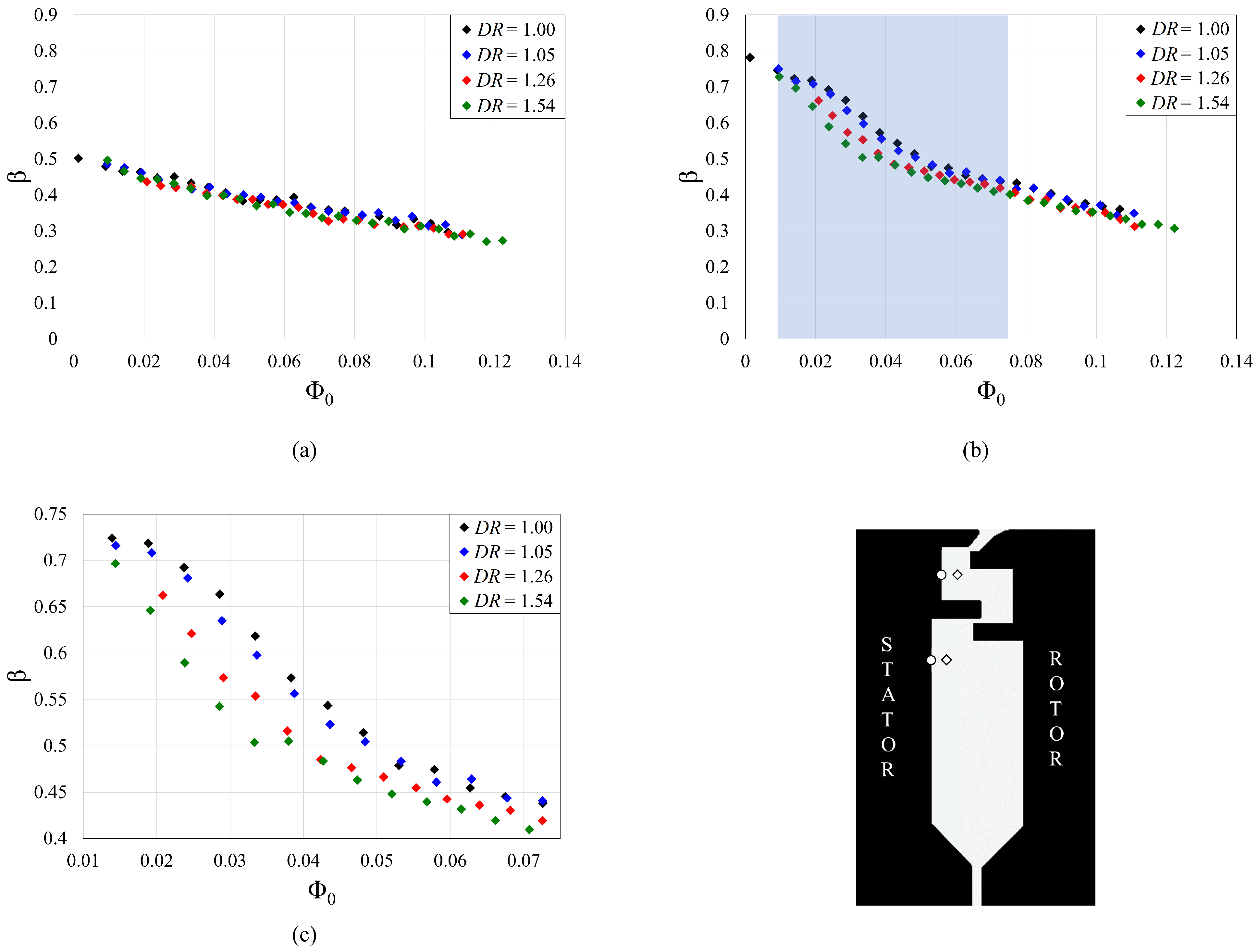
Corresponding measurements of total pressure are sampled with Pitot tubes to estimate the local tangential component of velocity, and hence the swirl ratio, as per Equation (2). The distribution of the swirl is presented in Figure 5 for a range of purge–mainstream density ratios and purge flow rates.
First, consider the distribution of the swirl ratio with the purge flow rate in the inner wheel-space. The suppression of swirl with purge is consistent with the pressure coefficient data seen in Figure 4 and in accordance with the theoretical predictions of Childs [11]. Again, an independence is seen with respect to the density ratio.
Second, consider the flow behaviour in the outer wheel-space. Figure 5b demonstrates a density-affected region (highlighted in blue) for intermediate levels of purge flow, where the the onset of core suppression occurs at lower levels of purge for higher purge–mainstream density ratios. The data are reproduced in Figure 5c to emphasise the effect of the density ratio. The swirl ratio is seen to be independent of the density ratio outside of this intermediate range of purge flow, consistent with that seen in the inner wheel-space. Graikos et al. [12] measured a similar inflexion in the distribution of the swirl with purge in the outer wheel-space when modifying the shear layer across the rim seal, albeit for data at a unity density ratio. This provides evidence that the purge–mainstream density ratio must modify the shear layer, as is often achieved by changing the annulus flow coefficient.

3.2. Species Concentration

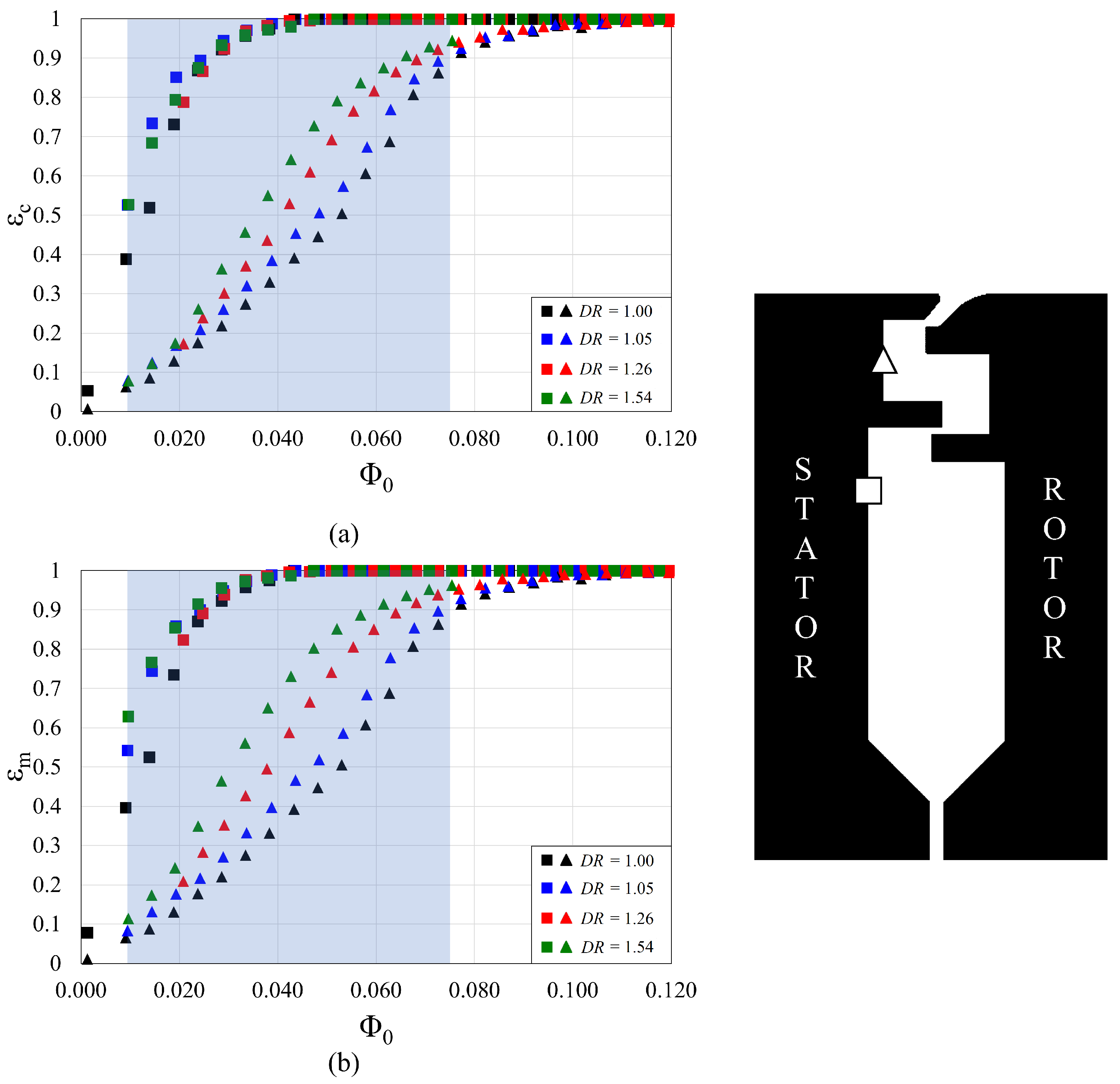
The distribution of sealing effectiveness with purge flow is presented in Figure 6a using the volume-based definition introduced in Equation (12). For comparison, the data are re-plotted in Figure 6b for the mass-based variant defined in Equation (13). In studies with a near-unity density ratio (as is typically employed by researchers to minimise the use of tracer gas), these plots would be near identical. Here, where the density ratio is significant, it is imperative to use the mass-based variant. The volume-based definition—although experimentally convenient—is unrepresentative of ingress, which fundamentally is a mass-based inertial phenomenon. Henceforth, our discussion refers solely to the mass-based data presented in Figure 6.
The sealing effectiveness in the inner cavity is unaffected by the density ratio, which is consistent with the observations in Section 3.1 concerning the swirl ratio. In the outer cavity, there is a clear effect of density on sealing effectiveness over an intermediate range of purge flows. When 0.01 Φ 0 0.075 , sealing effectiveness is improved with an increasing density ratio. This effect is corroborated by Orsini et al. [8] when considering mathematically consistent definitions of the purge flow parameter, as highlighted in Section 1.
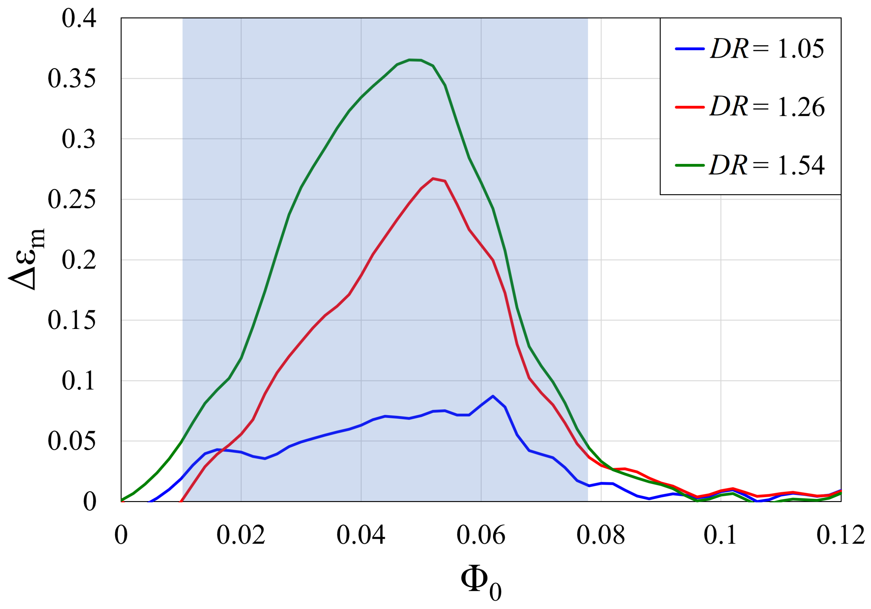
The relative effect of the density ratio (compared to the DR = 1.00 case) is characterised through Δ ε m , calculated through cubic interpolation between the datasets. The distribution of Δ ε m with Φ 0 is shown in Figure 7, with the density-affected region highlighted once again. The density-affected region was defined as existing for the range of Φ 0 where Δ ε m 0.05 for the D R = 1.54 case, chosen to highlight the region of greatest impact. The level of Δ ε m is increased as the density ratio is increased, with the maxima shifting to lower values of Φ 0 as the density ratio increases.
The effect of the density ratio on sealing effectiveness diminishes as Φ 0 > 0.08 . This can be also inferred from Figure 2, where, as the cavity of Orsini et al. approaches the sealed condition, the effect of density is seen to similarly weaken. The Ingress Wave Model derived by Tang et al. [9] suggests that the cavity should require a minimum sealing rate to seal the system which reduces with increasing density ratio. This hypothesis would result in the outer cavity in this study sealing at a lower Φ 0 for the D R = 1.54 case relative to the D R = 1.00 case.

3.3. Spectral Analysis

The ensemble-averaging methodology presented by Vella et al. [4] is utilised to compute the spectral distribution of the unsteady pressure within the rim seal. In this instance, the ensemble-averaging process, which occurs every 2.33 rotor revolutions, is applied to datasets spanning 140 full revolutions. The ensemble averaging is followed by a spatial average of the data acquired from multiple sensors positions across a vane pitch.
Tang et al. [9] describe the association between ingress and the presence of a circumferential gradient of pressure ( p / ϕ ), driven by shear across the rim seal. Consideration of the inviscid Navier–Stokes equations demonstrates the proportionality between local density and p / ϕ . Therefore, in a dimensional sense, ingress increases with an increased purge–mainstream density ratio, as demonstrated by Orsini et al. [8]. However, when considering the dimensionless inertial parameter Φ 0 1 / ρ 0 , an increase in the purge–mainstream density ratio has been seen to reduce the ingress of annulus gas (Figure 6).
The parameter ξ represents a non-dimensional power spectral density (PSD):
ξ = P S D ( 1 2 ρ 0 Ω 2 b 2 ) 2 · 10 5
where ρ 0 is measured at r / b = 0.969 in the outer wheel-space (in closest proximity to the radial position of the unsteady pressure sensors), and the PSD has units Pa2/Hz (calculated considering non-dimensional frequency f / f d ).
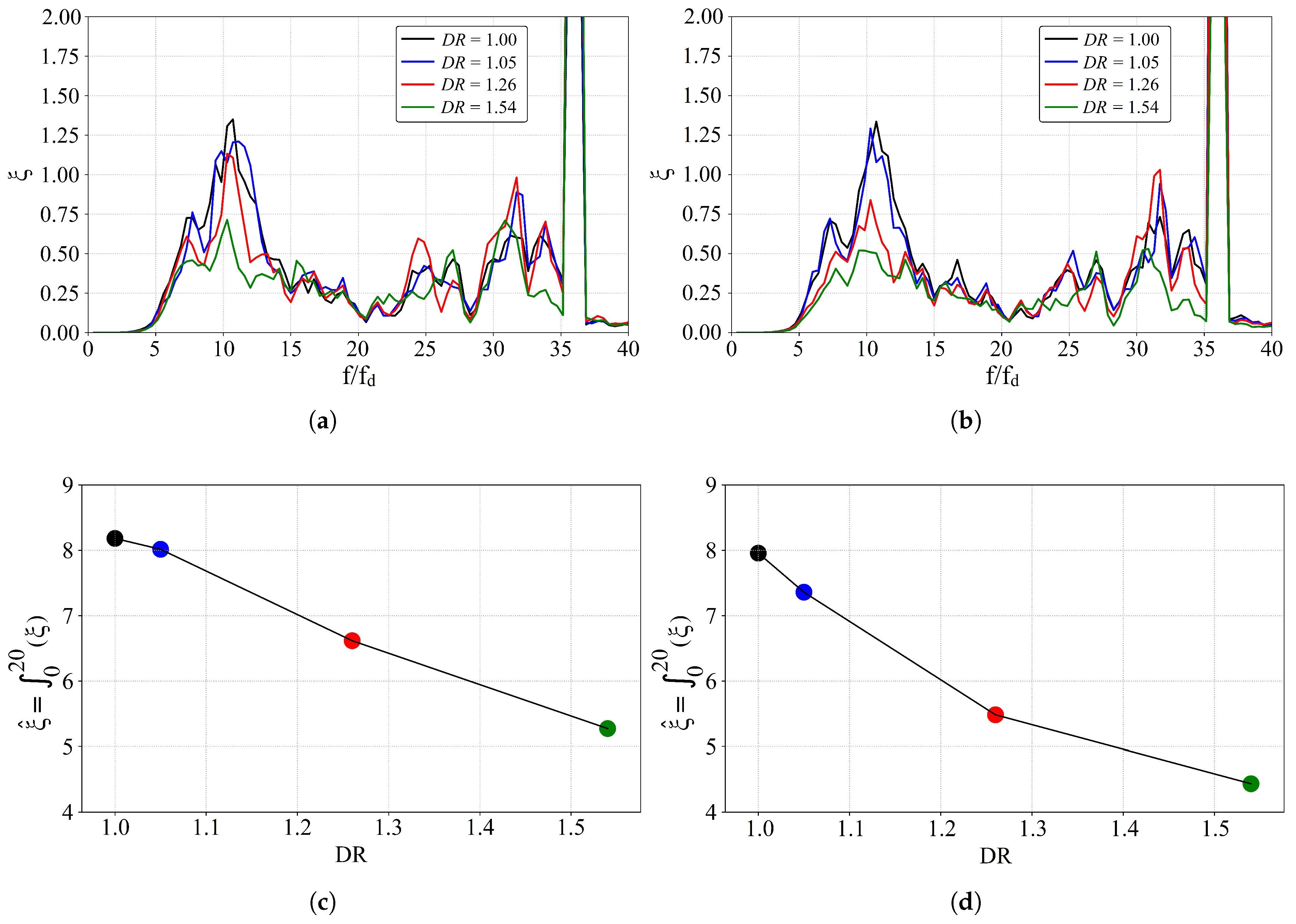
Figure 8 presents the variation of ξ with the density ratio at two Φ 0 conditions within the density-affected region. Persistent and distinct harmonic intervals are evident for all density ratios and Φ 0 conditions, in agreement with the experimental measurements of Vella et al. [4], who employed different operating conditions and an aero-engine-representative rim seal and investigated several radial seal clearances. The amplitude of the lower-frequency harmonic interval ( 5 f / f d 20 ) is a strong function of the density ratio, with the spectral content in this band decreasing as the density ratio is increased. However, the higher harmonic interval ( 20 f / f d 35 ) is largely influenced by the blade and its interaction with the wheel-space (computationally evidenced by Chilla et al. [13], amongst others), and, as a result, is broadly independent of the density ratio.
If Figure 8a,b is considered a representation of the energy cascade, the large scales associated with unsteady flow structures can be evaluated using the integral of ξ in the frequency domain:
ξ ^ = f / f d = 0 f / f d = 20 ξ d ( f / f d )
The definite integral has been approximated using Simpson’s rule in the range 0 f / f d 20 . Non-dimensional frequencies >20 have been omitted in order to minimise the impact of the blade, therefore isolating the effect of the density ratio.
For both Φ 0 conditions, the integral of non-dimensional unsteadiness ( ξ ^ ) decreases as density is increased; ergo, the circumferential gradient of pressure per unit density is reduced. The non-dimensional unsteadiness progressively reduces in line with the theoretical predictions of Tang et al. [9]. This trend is consistent with Figure 6, where the effectiveness is elevated with increasing density ratio at constant Φ 0 . The causal link between unsteadiness and ingress is maintained for all density ratios. Furthermore, the piece-wise gradients of the ξ ^ -DR curves are consistent with the relative magnitude of Δ ε m at corresponding levels of Φ 0 and DR (Figure 7).

4. Conclusions

Experimental measurements of pressure, swirl and species concentration were used to assess the effect of the purge–mainstream density ratio on hot gas ingress in a single-stage axial turbine test rig. The purge–mainstream density ratio was varied within the range 1.00 D R 1.54 . The main conclusions from this study are as follows:
  • In the outer wheel-space, increasing the density ratio promotes earlier suppression of the inviscid rotating core, and sealing effectiveness rises in accordance. In the inner wheel-space, the levels of swirl and effectiveness are largely independent of the density ratio.
  • The relative effect of density upon sealing effectiveness is amplified at intermediate levels of Φ 0 ( 0.01 Φ 0 0.075 ); this is most significant at lower values of Φ 0 as the magnitude of the density ratio increases.
  • The spectral distribution of non-dimensional unsteadiness, ξ , identified two distinct harmonic intervals: a low-frequency spectral band, which was suppressed as the density ratio was increased; and a high-frequency band associated with the blade. The former demonstrated a causal link between unsteadiness and ingress, which was maintained for all density ratios.
  • The integral of ξ —which represents the energy content at large scales ( ξ ^ )—decreased with the density ratio. This apparent reduction in unsteadiness is in accordance with the behaviour predicted by pre-published theoretical models.

Author Contributions

Conceptualisation, J.S.B., C.M.S. and J.A.S.; methodology, J.S.B., S.V., H.T. and C.M.S.; software, J.S.B. and S.V.; validation, J.S.B., S.V. and H.T.; formal analysis, J.S.B., S.V., C.M.S. and J.A.S.; investigation, J.S.B.; resources, C.M.S. and J.A.S.; data curation, J.S.B., S.V., C.M.S. and J.A.S.; writing—original draft preparation, J.S.B., S.V. and C.M.S.; writing—review and editing, J.S.B., S.V., C.M.S. and J.A.S.; visualisation, J.S.B. and S.V.; supervision, C.M.S., J.A.S. and G.D.L.; project administration, C.M.S.; funding acquisition, C.M.S. All authors have read and agreed to the published version of the manuscript.

Funding

The researchers would like to acknowledge the support received from the EPSRC Impact Acceleration Account institutional grant at the University of Bath, ref. EP/R51164X/1, and Siemens Energy Industrial Turbomachinery Ltd.

Data Availability Statement

Due to confidentiality agreements with research collaborators, supporting data can only be made available to bona fide researchers subject to a non-disclosure agreement. Details of how to request access are available at the University of Bath data archive website.

Acknowledgments

The authors would like to thank Andrew Langley for his ongoing support in maintaining the test facility and providing practical expertise throughout the campaign. Further thanks are given to Sam L’esteve for his expertise in maintaining the instrumentation and electrical systems in the test facility. Bjorn Cleton is acknowledged for his preliminary experiments which fuelled interest in the density ratio.

Conflicts of Interest

The authors declare no conflicts of interest. The funders had no role in the design of the study; in the collection, analyses or interpretation of data; in the writing of the manuscript; or in the decision to publish the results.

Appendix A. Uncertainty Analysis

An uncertainty analysis was initially conducted by Jones et al. [10] on the instrumentation of the LAR facility using the method presented by Moffat [14]. An extension to this uncertainty analysis is conducted here. For brevity, only the pressure coefficient is presented in full, with the estimated uncertainty and instrument specifications given in Table A1 and Table A2, respectively.
The definition of pressure coefficient, C p , is given as
C p = p p 0 1 2 ρ 0 Ω 2 b 2
The density of the purge flow is given by
ρ 0 = ( p 0 + p a t m ) M m i x R u T 0
where M m i x is defined as
M m i x = c 0 M C O 2 + ( 1 c 0 ) M a i r
The uncertainty can then be expressed as follows:
δ C p C p 2 = δ p 0 p 0 + p a t m 2 + δ p a t m p 0 + p a t m 2 + δ c 0 c 0 2 + δ T 0 T 0 2 + δ p p 2 + δ Ω Ω 2
where the error in b is considered negligible.
Table A1. Estimated measurement uncertainty.
δ Φ 0 / Φ 0 δ ρ 0 / ρ 0 ε c / ε c ε m / ε m δ C p / C p δ β / β δ ξ / ξ
± 4.4 % ± 0.43 % ± 3 % ± 3.1 % ± 4.7 % ± 6.7 % ± 4.7 %
Table A2. Precision and specifications of the instrumentation.
X i δ X i Scale Range (Units)Instrument
p 0.3 % Full Scale1 kPaPR3202V10-S0019-AB-00-00
p a , p 0 ±35 Pa35 kPa5 PSI-D-HGRADE-MV
p a t m ±50 Pa75 to 125 kPaPi642P-.75-1.25BARA-0.1
p u n s t e a d y ±0.1% Full Scale170 kPa absoluteXCQ-062-1G
T a , T 0 ±0.5 K3 to 1530 KK-type Thermocouple
Ω ±1 rpm6000 rpm34kW AC Dynamometer
m ˙ 0 , C O 2 ± 0.8 % Read, ± 0.2 % Full Scale3.0 kg/minMCR-1500SLPM-D
m ˙ 0 , a i r ± 0.3 % Read, ± 1 % Full Scale0.07164 kg/sF-206AI-ABD-00V
m ˙ a ± 1 % Read, ± 0.5 % Full Scale1.7 kg/s780-NAA-F9-EN2-P2-V3-DD-0
c s , c a , c 0 ± 0.1 % Full Scale100 % CO 2 by volume9120MG Multi Gas Analyser

References

  1. Cumpsty, N.; Heyes, A. Jet Propulsion; Cambridge University Press: Cambridge, UK, 2015. [Google Scholar]
  2. Bandini, A.; Bettini, C.; Peruzzi, L.; Carretta, M.; Canelli, C.; Marconcini, M.; Pinelli, L.; Arnone, A. Targeting Full-Hydrogen Operation on Industrial-Scale Gas Turbines: Impact of Unconventional Fuels on Turbine Module Performance and Aeromechanics. J. Turbomach. 2024, 147, 071008. [Google Scholar] [CrossRef]
  3. Chew, J.W.; Gao, F.; Palermo, D.M. Flow mechanisms in axial turbine rim sealing. Proc. Inst. Mech. Eng. Part C J. Mech. Eng. Sci. 2019, 233, 7637–7657. [Google Scholar] [CrossRef]
  4. Vella, S.; Tang, H.; Carnevale, M.; Scobie, J.A.; Lock, G.D.; Salvatori, F.; Sangan, C.M. On the Relationship Between Swirl and Unsteadiness Within Turbine Rim Seals. J. Eng. Gas Turbines Power 2024, 147, 041031. [Google Scholar] [CrossRef]
  5. Teekaram, A.J.H.; Forth, C.J.P.; Jones, T.V. The Use of Foreign Gas to Simulate the Effects of Density Ratios in Film Cooling. J. Turbomach. 1989, 111, 57–62. [Google Scholar] [CrossRef]
  6. Boldero, J.S.; Vella, S.; Tang, H.; Scobie, J.A.; Lock, G.D.; Sangan, C.M. The Effect of Purge-Mainstream Density Ratio on Rim Seal Fluid Mechanics. In Proceedings of the European Turbomachinery Conference, Hannover, Germany, 23–28 March 2025. ETC16-210. [Google Scholar]
  7. Johnson, B.V.; Daniels, W.A. Disk/Cavity Wall Cooling Effectiveness Experiments with Air and CO2 as Coolants. In Proceedings of the International Gas Turbine and Aeroengine Congress and Exposition, Birmingham, UK, 10–13 June 1994. 94-GT-68. [Google Scholar]
  8. Orsini, L.; Picchi, A.; Facchini, B.; Bonini, A.; Innocenti, L. Impact of the Purge Flow Density Ratio on the Rim Sealing Effectiveness in Hot Gas Ingestion Measurements. J. Turbomach. 2023, 146, 021002. [Google Scholar] [CrossRef]
  9. Tang, H.; Vella, S.; Sangan, C.M.; Scobie, J.A.; Lock, G.D. Ingress wave model with purge-mainstream density ratio. Int. J. Heat Mass Transf. 2025, 237, 126372. [Google Scholar] [CrossRef]
  10. Jones, R.R.; Pountney, O.J.; Cleton, B.L.; Wood, L.E.; Schreiner, B.; Carvalho Figueiredo, A.J.; Scobie, J.A.; Cleaver, D.J.; Lock, G.D.; Sangan, C.M. An Advanced Single-Stage Turbine Facility for Investigating Non-Axisymmetric Contoured Endwalls in the Presence of Purge Flow. In Proceedings of the ASME Turbo Expo 2019, Phoenix, AZ, USA, 17–21 June 2019. GT2019-90377. [Google Scholar]
  11. Childs, P.R.N. Chapter 7: Rotating cavities. In Rotating Flows; Elsevier: Amsterdam, The Netherlands, 2010. [Google Scholar]
  12. Graikos, D.; Carnevale, M.; Sangan, C.M.; Lock, G.D.; Scobie, J.A. Influence of Flow Coefficient on Ingress Through Turbine Rim Seals. J. Eng. Gas Turb. Power 2021, 143, 111010. [Google Scholar] [CrossRef]
  13. Chilla, M.; Hodson, H.; Newman, D. Unsteady Interaction Between Annulus and Turbine Rim Seal Flows. J. Turbomach. 2013, 135, 051024. [Google Scholar] [CrossRef]
  14. Moffat, R.J. Describing the uncertainties in experimental results. Exp. Therm. Fluid Sci. 1988, 1, 3–17. [Google Scholar] [CrossRef]
Figure 1. Contributing mechanisms for ingestion through turbine rim seals.
Ijtpp 10 00046 g001
Figure 2. The mass-based effectiveness adapted from Orsini et al. [8] when based on (a) the modified  Φ F i parameter and (b) the original definition of Φ 0 for C F = 0.32.
Ijtpp 10 00046 g002
Figure 3. A section view of the Large Annulus Rig (LAR) highlighting the wheel-space and instrumentation.
Ijtpp 10 00046 g003
Figure 4. Distribution of pressure coefficient with purge flow rate and density at (a) r / b = 0.866 and (b) r / b = 0.969.
Ijtpp 10 00046 g004
Figure 5. Distribution of swirl ratio with purge flow rate and density at (a) r / b = 0.866 and (b) r / b = 0.969. The density-affected region is highlighted in blue and subsequently reproduced in (c) in expanded form. The silhouette highlights the measurement locations of static pressure (circles) and total pressure (diamonds).
Ijtpp 10 00046 g005
Figure 6. Distribution of sealing effectiveness with purge flow rate, defined as (a) volumetric effectiveness and (b) mass-based effectiveness. The density-affected region is highlighted in blue.
Ijtpp 10 00046 g006
Figure 7. The relative effect of the density ratio as characterised by Δ ε m , compared to the near-unity case. The density-affected region is highlighted in blue.
Ijtpp 10 00046 g007
Figure 8. Spectral distribution of non-dimensional unsteadiness at (a) Φ 0 0.030 and (b) Φ 0 0.043 and the corresponding evaluations of ξ ^ at (c) Φ 0 0.030 and (d) Φ 0 0.043 for a range of density ratios.
Ijtpp 10 00046 g008
Table 1. Design operating conditions of the Large Annulus Rig.
ParametersValue
Disc Speed [rpm]900
Rotational Reynolds Number, R e ϕ 5.9 × 10 5
Axial Reynolds Number, R e w 2.2 × 10 5
Flow Coefficient, C F 0.38
Vane Exit Mach Number, Ma0.12
Non-Dimensional Sealing Flow Rate, Φ 0 0.00–0.13
Density Ratio, DR1.00–1.54
Disclaimer/Publisher’s Note: The statements, opinions and data contained in all publications are solely those of the individual author(s) and contributor(s) and not of MDPI and/or the editor(s). MDPI and/or the editor(s) disclaim responsibility for any injury to people or property resulting from any ideas, methods, instructions or products referred to in the content.