Abstract
In this article, deployable cylindrical vaults of reciprocal linkages with frustoconical ends are analysed. Deployable cylindrical vaults with quadrangular scissors modules have low stiffness in the longitudinal direction, which requires the use of stiffening bars after deployment. The truncated cone-shaped ends improve their stiffness but do not prevent bracing. However, if reciprocal knots are used, the mesh performance improves considerably. This article studies the design conditions of these vaults and their resistance to gravity, wind suction and wind loads in the transverse and longitudinal directions. We also study the different resistance behaviour of the mesh, depending on whether the roof is supported on the upper or lower joints. In all cases, model tests are carried out to check the validity of the proposed solutions. Both theoretical calculations and experimental tests demonstrate the viability and effectiveness of this type of structure.
1. Introduction
Transformable structures are defined as those that can modify their shape to adapt to different situations of use. They are highly interesting architectural solutions that can offer dynamic responses to current problems. They have traditionally been designed as transportable elements that can be deployed to create temporary spaces or fixed enclosures in response to climatic influences and change in use, in a society that is increasingly interested in sustainable design.
One particularly interesting type of transportable structures is the deployable bar structures. Various systems have been proposed, but the ones that have reached the highest level of development are the three-dimensional modules consisting of scissor-like-elements (hereafter SLEs). These are pairs of bars with a pivot joint at the central point and joints at the ends. By joining several of these modules together, it is possible to create structures that can be folded into a compact package and transported to the desired location. Once there, they can be deployed to form an enclosure capable of meeting different needs. Our team has studied numerous applications of these structures and has recently focused on emergency buildings for disaster situations [1].
After some historical precedents with little development, the first effective deployable structures were designed and built by the Spanish architect Emilio Pérez Piñero using bundle modules [2,3]. These are modules formed by sets of three or four bars, which are articulated around a central pivotal joint and linked together at the ends. With these modules, Pérez Piñero built the first modern folding structure in the pavilion for the XXV Years of Peace exhibition in 1964 [4].
In the 1980s, interest in this type of structure, which had almost come to a standstill after Pérez Piñero’s early death, was revived. Escrig and Pérez Valcárcel developed a large set of structural types based on SLEs that have great advantages over bundle modules. With triangular modules, very rigid structures can be achieved, but the joints are more complicated since they articulate six bars [5]. On the other hand, with square modules, very simple structures can be achieved with much cheaper knots because of the four bars [6]. This is a fundamental aspect, since the joints represent a high percentage of the final cost of the structure.
The main problem with square module deployable structures is their lack of transverse stiffness. Several solutions have been proposed to solve this problem. Gantes designed a system with square modules diagonalised by SLEs [7]. It is a very effective system, but the joints are more complicated and expensive and also increase the number of members and therefore the weight of the structure. Hernandez proposed another solution with the design of vaults with embouchures [8]. By breaking the longitudinal profile, the structure becomes more rigid in this sense, which is the most unfavourable. Studies by Escrig and Pérez-Valcárcel, as well as the construction of various prototypes such as the ESTRAN by Hernández and Zalewsky show that the textile roof provides sufficient bracing for small or medium spans [9], but for larger spans, it would be necessary to add external elements. This is a construction complication, as was seen in the two 30 m span domes of San Pablo in Seville built by Escrig, Sánchez and Pérez-Valcárcel, where it was necessary to install stiffeners, as the textile was not strong enough [6]. The geometrical conditions for the design of deployable structures of various shapes were studied by Sánchez-Cuenca, who proposed a method based on the tracing of ellipses that has proved to be particularly simple and effective [10,11]. Based on this method, Ponce and Sánchez-Sánchez studied the correct design of truncated conical meshes [12], and later García-Mora and Sánchez-Sánchez analysed the more general conditions for complex shapes based on continuous guidelines, using ellipsoids [13,14,15]. Freire et al. introduced the semi-regular SLEs that facilitate the solution of broken guidelines with polar SLEs [16].
Deployable structures with articulated linkages are mechanisms, so they can be opened without control until the external restraints are fixed. One option to limit deployment is the use of bistable modules. This is a line of research in which there has been a long series of very interesting contributions. Bistable structures are those that are geometrically compatible only in two positions, namely fully folded and deployed in a position that can be determined a priori. Moving from one position to the other involves providing energy to initiate the unfolding and overcome the incompatible positions. This energy is returned by the structure in the final stages, completing the unfolding itself and stabilising in its final position.
Gantes [7] first pointed out this phenomenon and recently there has been a great development in the study of bistable structures. The work of Gantes and Konitopoulou [17], García-Mora and Sánchez-Sánchez [13], Roovers and De Temmerman, Arnouts et al. [18,19] or Freire et al. [20,21,22] can be cited. It has also been the subject of several studies on triangular vaults or triangular module domes, incorporating the energy balance of the structure in the deployment process [23]. All these examples propose and analyse structures whose final shape is fixed after deployment.
Another way to stabilise the structure in a predetermined end position is the use of reciprocal linkages, which have been patented by the authors [24]. The idea is that the bars are supported at their ends by the other concurrent bars, limiting the opening to the desired point. In addition, the reciprocal joints make it possible to achieve stiffer structures and reduce the bending stresses in the bars [25]. Pérez-Valcárcel et al. analysed the design and resistance conditions of such linkages [26] and proved the effectiveness of this system in structures formed by SLEs [27], as well as by bundle modules [28]. An important advantage of the use of reciprocal linkages is that it allows the opening of the mesh to be limited without the use of bistable modules. The structure is stabilised in its final position when the reciprocal support of the bars occurs.
This article analyses the application of this system to cylindrical vaults with truncated cone-shaped ends (Figure 1). The solution of the ends is one of the problems of cylindrical vaults [27] and the use of this type of ends allows a more functional solution and improves the lateral stiffness of cylindrical vaults, which is much reduced in the case of deployable meshes with articulated linkages. In addition, the use of the reciprocal ones provides a very important lateral stiffness, which until now could not be precisely determined. This is especially important in the study of longitudinal wind action on these structures.
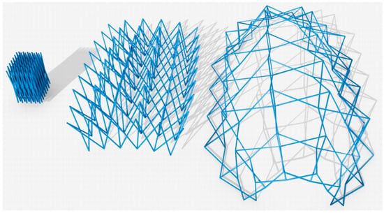
Figure 1.
Deployable cylindrical dome with truncated cone-shaped ends.
The proposed system uses a linkage formed by a hollow section to which the bars are connected laterally on pivots welded to the linkage. By extending the bar from the axis of the joint, it can be achieved that the bars that concur in the linkage rest on each other, forming a reciprocal support (Figure 2a), whereas without such an extension, the joint linkage is simply articulated (Figure 2b). The reciprocal linkage allows the structure to unfold to a final position that cannot be exceeded. At the same time, the structure in deployed position has greater stiffness, smaller displacements and lower bending stresses [25].
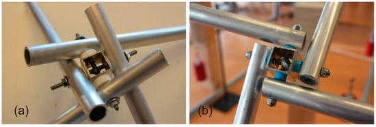
Figure 2.
Reciprocal (a) and articulated (b) linkages used in the model.
Depending on the linkage and member dimensions, embedment degrees between 85% and 96% can be achieved in structures with normal dimensions [27,28]. This works only in the direction of the reciprocal support on the adjacent member, while in the lateral direction, the member would only be constrained by the stiffness of the bolts in the joint. However, it will be seen in this paper that reciprocal meshes provide remarkable stiffness in this direction as well.
The behaviour of these structures under non-gravity loads in the upper and lower layers will also be addressed, since only gravity loads have been analysed so far [27]. The behaviour of a vault with truncated cone ends is now studied, which allows for greater stiffening and reduces the height of the spandrels, facilitating closure solutions. Since the roof can be fixed on the top or bottom layer of the mesh, gravity actions are studied assuming that the loaded joints are in each of these layers. Wind suction in both layers and the transverse and longitudinal wind action will also be analysed.
The aim of this paper is to analyse the behaviour, both theoretical and experimental, of deployable cylindrical meshes of reciprocal linkages with truncated cone-shaped ends, in order to gain an in-depth understanding of their structural response and strength advantages.
The originality of this article focuses on the following aspects.
- The study of the conditions for the design of cylindrical vaults with truncated cone-shaped ends, using reciprocal joints.
- The analysis of the influence of the placement of the cover on the upper or lower layer of the mesh on the general behaviour of the structure.
- The study of the effect of the inversion of forces caused by wind suction on the reciprocal support of the joints.
- The analysis of the effects of cross wind on the roof.
- The analysis of the wind on the extreme tympana in the unbraced reciprocal joint mesh and its response to a theoretically unstable situation.
This article first analyses the geometrical, constructive and resistant characteristics of the proposed solutions (Section 2). The materials and methods used in the experimental analysis are described (Section 3) and the results obtained (Section 4). In Section 5, these results are analysed by making a comparative study between the theoretical and experimental results and by comparing the results of the tests with loads applied on the top or bottom layer of the structure. Conclusions and prospects for future developments are presented in Section 6.
2. Description of Expandable Cylindrical Meshes with Reciprocating Linkages with Frustoconical Ends
In [27], different types of deployable cylindrical meshes have been analysed by our team. The performance of the different types of vaults was studied considering various span/height ratios.
Cylindrical meshes have the disadvantage that the tympana have to be closed with a flat element of the same dimensions as the cross-section. In many cases, this requires an auxiliary structure to be assembled after deployment, which causes a delay in execution (Figure 3). It is desirable to design solutions such as truncated conical ends both to achieve smaller tympana and to give more stability to the structure (Figure 4). They can also be used as entrances to the enclosure.
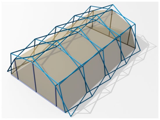
Figure 3.
Deployable cylindrical mesh with flat tympana.
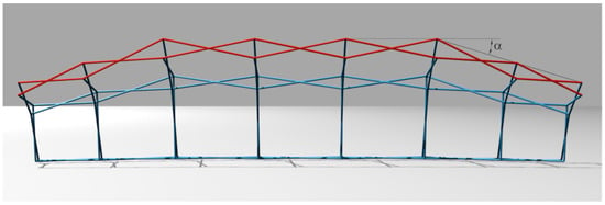
Figure 4.
Longitudinal section of one half of a cylindrical deployable mesh with frustoconical ends.
It is simple to design conical vaults that meet the conditions of foldability following the method of Ponce and Sánchez [12] and that conform to a cylindrical vault at its ends (Figure 5). The SLEs in the longitudinal direction are shown in red and the SLEs in the transverse direction are shown in blue. A vertex of the cone O is defined with the desired angle α (Figure 6). To adjust the lengths of the first SLE, draw an ellipse E1 with foci at points 1 and 2 and which passes through point 3’. This ellipse cuts the midline of the conic dome at point 3 and by prolonging the SLE sections, points 4 and 5 are defined. The ellipse E2 with foci at 4 and 5 and which passes through 3 allows the definition of point 6 and thus the next SLE. By continuing the process, any number of sections can be defined. The transverse arcs are proportional to the vertical distances 4–5 and 7–8, which makes it possible to calculate their lengths. This layout also makes it easy to define the angles formed by the SLEs with the joints, which is essential for the design of the reciprocal linkages.
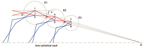
Figure 5.
Layout of conical meshes joined to a cylindrical one.
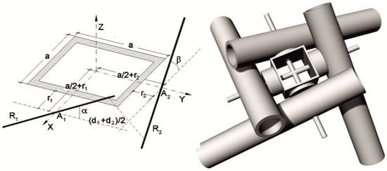
Figure 6.
Reciprocity condition for square meshes.
As in straight cylindrical vaults, linkages with eccentric bar axes are used to enable reciprocal support, and the conditions for reciprocal support depend on the angles between the bars of the adjacent SLEs. In the upper layer, the angles between the SLE bars are large, allowing the use of small diameter linkages. On the other hand, the bars of SLEs in the lower layer form small angles and in many cases even forming a reflex angle. The most reasonable solution is for the bottom layer linkages to be simply articulated [27]. Figure 2 shows the two types of linkages.
The change from cylindrical to conical vaulting makes the angle of the 1–3–5 bar considerably larger than the other SLEs that are connected to the linkage. This requires a specific treatment of this linkage, whose size would be smaller than that of the other linkages of the mesh. For this reason, an adjustment system has been used as detailed below.
2.1. Design of Reciprocal Linkages
The proposed reciprocal linkages are formed by four bars pivoting on horizontal axes that come out of the linkage, which can be formed by a cylinder or a prism, solid or hollow (Figure 2 and Figure 6). In order to achieve reciprocal support, the linkage must have an exact dimension that depends on the diameter of the bars and the desired opening angle. In cylindrical vaults, the opening angles of the bars are different: α, β. These meshes usually have higher stresses in the transverse direction than in the longitudinal one. Therefore, the diameters of the bars used are often different. In this case, washers of different thicknesses have been placed between the joint and the bar to achieve a gap larger than the radius of the bar and to be able to adjust the joint at different angles. For a more general formulation, a is considered to be the width of the linkage, r1 the distance from the edge of the knot to the axis of the bar in one direction, r2 the distance in the perpendicular direction and d1 and d2 the diameters of both bars. The value ri corresponds to the thickness of the washer plus the radius of the bar.
The effective size of the knot including washers in each direction is
To calculate the base value of joint a, the position of the axes of the two bars of diameters d1 and d2 is taken as shown in Figure 6. The straight lines R1 and R2, which correspond to the axes of the bars, pass through the points A1 and A2 and form angles α and β with the reference plane. Their unit vectors are
Its crossing points are
The distance between two intersecting lines is the mixed product, divided by the modulus of the vector product. This distance is the sum of the radii of the bars, considering that these bars touch at the point of contact.
This expression does not allow us to obtain the value of the size of the base joint a explicitly. On the other hand, it is very easy to calculate it iteratively with a simple computer programme, as has been performed in the design of the tested model.
2.2. Calculation of Meshes with Reciprocal Linkages
The most suitable calculation method for deployable bar structures is matrix structural analysis, which has been widely used by our team. A computer programme was developed that was subject to successive improvements including the non-linear effects due to the bending of the bars and the effect of the eccentricity of the bars on the joints [29]. Since version DESPLEG 19 has incorporated the effect of stiffening bars due to reciprocal support on others, which has been published in various articles [25,27].
The effect of reciprocal support implies a degree of embedding of the bar in the plane of the scissors that can reach up to 98%. It represents a very notable improvement in the performance of the deployed structure against gravitational loads and wind suction loads, as will be seen in Section 6. However, the matrix methods of articulated joints are not suitable for lateral loads on the tympana. A structure of square modules is a quasi-mechanism for these loads, so it needs bracing elements that can be cables, bars or the textile cover itself. If these bracings do not exist, the calculated lateral displacements are very strong, even taking into account in this case the favourable effect of the conical ends.
For this reason, a new calculation was performed for the wind over the tympana considering the hypothesis of linkages with different degrees of rigidity. For this, the RIGID programme version 3.1 [30] was used. It is a very powerful matrix calculation programme with variable degrees of embedment of the bars in the joints. The results have been very close to those measured, as will be seen.
2.3. Mesh Description
To carry out the tests, a model was built with plan dimensions of 4.83 × 3.65 m and a maximum height of 1.83 m. Figure 7 shows the built model and a diagram of it with dimensions.
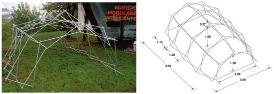
Figure 7.
Test model.
The model has its supports in the horizontal plane, which allows it to be fixed to the ground. For the tests, the lower joints were screwed to omega profiles, which in the case of the real structure allow the panels that form the floor of the building to be placed between them. For the intended use as an emergency enclosure, it is considered that the cover will be textile and in such a way that it can be folded with the assembly. The folding conditions of the textile cover have been widely analysed in previous publications [31]. It is also possible to provide a rigid cover that would be attached to the mesh once deployed.
2.4. Loading Hypotheses Analysed
The previous tests carried out by our team on reciprocal linkage structures referred to models loaded in these joints [26,27,28]. However, in several practically useful structures it may be convenient to place the cover on the lower layer with articulated joints without reciprocal support, as occurs in cylindrical vaults.
This article analyses the response of these structures to loads that may be applied to any of the layers of the structure. This allows us to compare the advantages of placing the cover in one position or another.
Seven load hypotheses have been analysed both theoretically and experimentally.
- Gravitational loads on the upper layer of the mesh;
- Gravitational loads on the bottom layer of the mesh;
- Wind suction on the top layer of the mesh;
- Wind suction on the bottom layer of the mesh;
- Transverse wind over the upper layer of the mesh;
- Transverse wind over the bottom layer of the mesh;
- Longitudinal wind on the tympanum.
In all of them, loads of 10 kgf (98.1 N) and 5 kgf (49.05 N) have been applied. These loads are similar to those of a real structure, considering the laws of physical similarity, but an exact transposition has not been attempted. The aim is to define load values that allow the theoretical results to be compared with the experimental ones.
3. Materials and Methods
3.1. Test Model
The model to be tested corresponds to a cylindrical mesh to which two truncated conical meshes are added at its ends. In each cross-section, all the SLEs are equal, while longitudinally, the central ones are straight and those at the ends are asymmetrical translational SLEs drawn with the system in Figure 5. The model has separation washers between bars at the inner joint to prevent lateral bending. It is an aspect already studied by our team that showed that small eccentricities in the intermediate joint do not hardly affect the performance of these structures [27].
The result is a model composed of eight square modules in the cylindrical area and another four at each end forming the two conical ends. The plan dimensions of the model are 3652 × 4834 mm, its maximum interior height is 1555 mm, and its exterior height is 1826 mm, which represents a 1:3 scale with respect to reality. In the cylindrical area, the distances between the axes of rotation are 606 and 718 mm in the transverse SLEs are 659 mm in both sections of the longitudinal SLEs. These dimensions are reduced in truncated conical ends.
The bars are articulated in the lower layer and with reciprocal linkages in the upper one. In these, the bars extend 30 mm from the axis of the extreme pivot. The inclinations of the bars on the joint are different in the cylindrical zone and in the truncated conical zone, so the proportion between the theoretical size of the joint and that of the bar (a + 2ri-d)/d is different in both zones. A 20 mm knot was used in all cases, and the distance was adjusted with washers.
The model was fixed on omega profiles onto which the starting joints of the inner and upper layers were screwed. These profiles allow horizontal forces to be balanced, so that only vertical loads are transmitted to the ground. In the gravity load tests, it was not necessary to fix the structure to the ground, while in the wind tests, the omega profiles were fixed with elements of sufficient weight to act as ballast.
In all cases, the possibility of the textile cover being located on the upper layer or on the lower layer was analysed. For this, tests were carried out placing the loads in each of the layers.
3.2. Materials
The bars of the test model are aluminium tubes type 6060 (aluminium-magnesium-silicon) state T5 of Ø16 mm and 1.5 mm-thick, with a specific weight of 2700 kN/m3, an elastic modulus of 69,500 N/mm2, elastic limit of 185 N/mm2 and breaking load of 220 N/mm2. Supplied by Extrugasa, Valga, Pontevedra, Spain.
The linkages are formed from sections of 20 × 20 × 20 mm and 1 mm-thick aluminium hollow tube (SHS) of the same quality. The pivots are formed with 4 mm threaded steel rods that are welded in the central part. The screws and threaded rods are made of quality 5.6 steel according to ISO 898-1 [32], with an elastic modulus of 200,000 N/mm2, elastic limit of 300 N/mm2 and breaking load of 500 N/mm2 with an elongation of 20%. To achieve reciprocal support of the linkages, plastic washers have been placed that allow the exact separation of the axis of the linkage to be set, as seen in Figure 2.
3.3. Testing Organisation
The tests were carried out in the structures laboratory of the ETS Architecture of A Coruña with a test bench of its own manufacture. Loads of 10 kgf (98.1 N) and 5 kgf (49.05 N) have been applied at the joints indicated in each test (Figure 8). The displacements have been measured with inductive displacement sensors Sm407.100.2.T from Schreiber Messtechnik GmbH, Oberhaching, Munich, Germany with linearity < 0.25% and deviation < 0.01%/°C. Data collection has been completed with NTK021 digital extensometers from Neoteck Technology LTD, Hong Kong, China with a precision of ±0.1 mm. The displacements have been measured at the most significant points of the mesh, carrying out loading–unloading cycles.
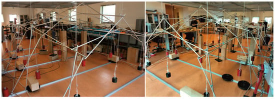
Figure 8.
Model used in tests.
In all tests, a previous loading step was carried out so that the linkages adjust, which is important in these models. Deployable structures are mechanisms, so the joints must have some tolerance that allows movement. With the initial load, the structure readjusts to a stable position, and in subsequent tests, it deforms depending on the applied load. This is essential if you want to validate the calculation methods with the experimental results. Adjustment shifts would distort the measured results and prevent effective contrast.
When carrying out the tests against lateral actions in a longitudinal direction, it was observed that the mesh had a much greater lateral rigidity than the theoretical calculations suggested. For this reason, a new test was carried out to determine if the lateral support at the joints could justify the fact that the lateral displacements are much smaller than those proposed in the calculation. A Mark-10 test bench, model EG100 (Interworld Highway, LLC, Long Branch, NJ, USA), was used with a precision of 0.1 N, and the deformation was measured with a NTK021 digital extensometer with a precision of ±0.1 mm. The results showed that although there is a certain degree of embedding, it is very small and in no way allows the observed discrepancies to be justified, as will be seen in Section 6.
4. Results
The main objective of the tests carried out is to analyse the differences in behaviour of the mesh with different types of loads applied successively to the upper or lower layers. It must be taken into account that the linkages of the upper layer are reciprocal and those of the lower layer are articulated.
The unfolding behaviour of the structures formed by SLEs shows that when gravity acts on the upper layer with supports on the lower one, the structure tends to open. At the end of this process, the reciprocal linkages support each other and the structure is more effective. On the contrary, with the loads applied to the lower layer, the structure tends to close, so the reciprocal linkages can lose effectiveness, at least in part. The results are quite different depending on which layer the charges act on, so it is necessary to study both situations separately.
4.1. Theoretical Model
The different tests carried out on the described model have been verified using the Despleg22.1 programme that uses matrix structural analysis. Table 1 indicates the geometric characteristics of the linkage in each case, which allow the determination of the thickness of the placed washers and the degree of embedment, which are entered as data in the programme. The lower joints are articulated so the degree of embedment is zero. The inner joints of the bars have a pivoting connection: the displacements of both points attached to the joint are equal, but the bars can rotate freely in the plane of the scissor.

Table 1.
Geometric characteristics of the linkage.
In reciprocal knots, the degree of embedment is the calculated one. When four bars occur in the linkage, it applies to all the bars. In this model, it only occurs in the interior joints of the upper layer. In edge and corner joints, it can only be applied to bars that mutually support each other. The bottom layer linkages and unsupported bar ends are hinged, with a degree of embedment of 0%.
Constraints are applied in order to consider the effect of the lower support bars. The loads are those of the real model and the results refer to the application points of the sensors. In each of the load hypotheses, the model has been calculated in two assumptions, considering all joints as articulated or with reciprocal joints. The results of both theoretical calculations are attached to each test.
4.2. Experimental Results
The following graphs indicate the application points of the loads and displacement sensors corresponding to each test. An entry into progressive loading was performed for about 15 s. The load was maintained for a period of time sufficient to fully stabilise the movements and then progressively unloaded for 10 s. For each of the cases, four tests were carried out. In all tests with vertical loads, loads of 10 kgf were placed at the interior points and 5 kgf at the tympana. The average values obtained are highlighted in bold.
4.2.1. Gravitational Loads on the Upper Layer of the Mesh
Figure 9 includes the graph of test 2 of the four carried out, with substantially the same results. The measured results are indicated in Table 2.
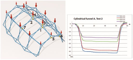
Figure 9.
Gravity load test on the upper layer of the mesh.

Table 2.
Vault test with frustoconical ends. Gravity load on upper layer.
4.2.2. Gravitational Loads on the Bottom Layer of the Mesh
In this case, the loads are placed in the linkages of the lower layer, which are articulated without reciprocal support (Figure 10). When loading, there is a faster descent in the ridge joints, which causes the lateral linkages to rise slightly at first. Subsequently, the structure is stabilised in its final position under load. When unloading, the same phenomenon is reproduced and then the structure stabilises with hardly any residual deformations.
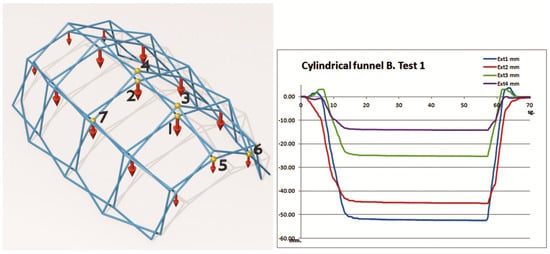
Figure 10.
Gravity load test on the lower layer of the mesh.
In this case, discrepancies occur in the results of joints 3 and 4, which correspond to the upper layer. When the load is applied to the joints of the lower layer, it is observed that some joints in the upper layer lose the contact that makes them reciprocal, so their deformations are closer to the hypothesis of articulated knots than reciprocal knots (Table 3). This is an effect that can be observed in other tests.

Table 3.
Vault test with frustoconical ends. Gravity load on lower layer.
4.2.3. Wind Suction on the Top Layer of the Mesh
In this test, the loads that simulate the action of wind are located in the upper layer in which the joints have reciprocal supports (Figure 11). The loads are placed vertically, since the width of the tested model exceeded the dimensions of the load bench. The aim was to analyse whether the suction situation could cause the reciprocal supports to stop functioning as such. The behaviour is almost linear under load with slight oscillations of very little significance and then they stabilise in their deformed position. The unloading is almost linear with small residual strains that tend asymptotically to zero.
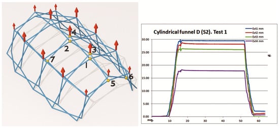
Figure 11.
Wind suction test on the upper layer of the mesh.
In this case, only the vertical components of the suction were analysed, for the indicated reason. However, the main interest of this trial was to validate the influence of effort investment on reciprocal support, which remains effective even when the direction of the loads changes. The results are quite adjusted to the theoretical model, although a greater discrepancy is observed in joint 4, where it was observed that some of the bars had lost contact in the reciprocal linkage (Table 4).

Table 4.
Vault test with frustoconical ends. Wind suction on upper layer.
4.2.4. Wind Suction on the Bottom Layer of the Mesh
In the suction test on the joints of the lower layer, the trends observed for the gravitational load are reproduced, with the same displacement inversion scheme (Figure 12). It is considered that this is due to the lack of rigidity of the knot when it is articulated, since these phenomena are more noticeable when the loads are located in the lower layer.
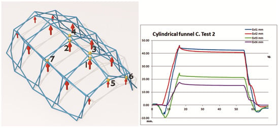
Figure 12.
Wind suction test on the lower layer of the mesh.
As in the previous case, the results are quite close to the theoretical model (Table 5). The most notable discrepancies occur in joints 3 and 4, also due to having lost contact of some bars in the reciprocal linkage.

Table 5.
Vault test with frustoconical ends. Wind suction on lower layer.
4.2.5. Transverse Wind over the Upper Layer of the Mesh
This test attempts to simulate the effect of the wind in a transverse direction to the mesh, which produces pressures to windward and suctions to leeward. The loads are applied to the joints of the upper layer in the manner indicated in Figure 13. The entry into load is less uniform than in previous tests, which causes a curious phenomenon of buckling in the mesh that especially affects the joint 3. Because of the occasional loss of reciprocal support, which has already been indicated, the applied loads cause different effects on the joint. The load applied to joint 1 causes joint 3 to rise. On the contrary, the load on joint 5 and its symmetry cause joint 3 to descend. A similar effect occurs on joint 4, although with less intensity. When loading at different times, there is an inversion of the displacements, which causes the values measured at linkages 3 and 4 to be much lower than those predicted in the theoretical calculations (Table 6).
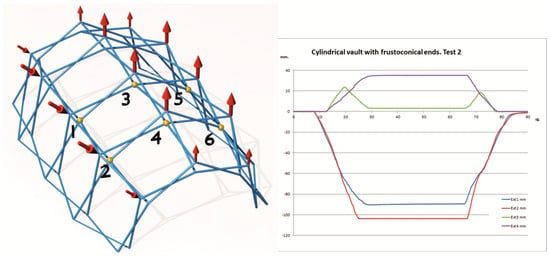
Figure 13.
Transverse wind test on the upper layer of the mesh.

Table 6.
Vault test with frustoconical ends. Lateral wind. Upper layer.
4.2.6. Transverse Wind over the Bottom Layer of the Mesh
This test was carried out in the same way as the previous one, but the loads were applied to the joints of the lower layer of the mesh (Figure 14). In this case, oscillations occurred in the loading and unloading sections, caused because the loads do not come into load simultaneously due to small errors in the model and since it is loaded at the lower joints, it is very sensitive to this effect. The displacements are greater than in the previous case, but no buckling phenomenon occurs.
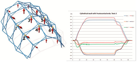
Figure 14.
Transverse wind test on the lower layer of the mesh.
In this case, the results fit very well with the theoretical model (Table 7).

Table 7.
Vault test with frustoconical ends. Lateral wind. Lower layer.
4.2.7. Longitudinal Wind on the Tympanum
This test is considered the most interesting and innovative of those carried out. In this case, the structure was fixed to the base by means of ballast elements and forces were applied to the tympanum that reproduce the action of wind in a longitudinal direction (Figure 15). The structure theoretically lacks lateral rigidity, since it does not have bracing, but when tested, relatively small displacements were observed, as seen in Table 8. The tests were carried out with a load of 10 kgf at the central point and two of 5 kgf on the sides. After an initial charge–discharge cycle, four tests were carried out, with very similar results.
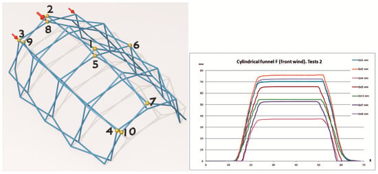
Figure 15.
Longitudinal wind test on the tympanum.

Table 8.
Vault test with frustoconical ends. Wind on the tympana.
This behaviour, better than expected, may be due to the rigidity of the linkage itself or the possible effect of reciprocal support in the horizontal direction. To determine this issue, a bending test was first carried out, applying a point load to an aluminium bar identical to those used in the model. It was first tested in simple bending and then fixed to two linkages like those used in the model that were rigidly attached to the base, in order to determine the possible stiffening effect.
Comparing the deformation measured in both tests, the results indicate that the degree of embedment achieved is very small, only 3%. Consequently, it is considered that the effect of the transverse stiffness of the joint is clearly insufficient and does not explain the discrepancy between the theoretical and experimental models (Figure 16).
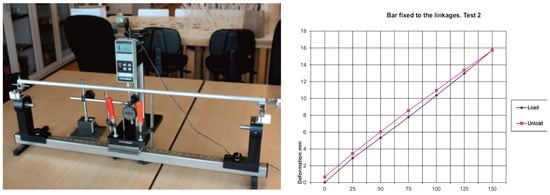
Figure 16.
Linkage stiffness test.
Since the intrinsic stiffness of the knot cannot explain the experimental results, it seems evident that the stiffness of the knot caused by the reciprocal support and the effect of the embouchure is much higher in the horizontal direction than was assumed. To verify this, new calculations were carried out using the Rigid programme [30], which considers that the knots have a degree of embedment both in the direction of the reciprocal knot and in the direction orthogonal to it. Different degrees of embedment were tested, obtaining the greatest agreement with the experimental results with a value of 80% (Figure 17).
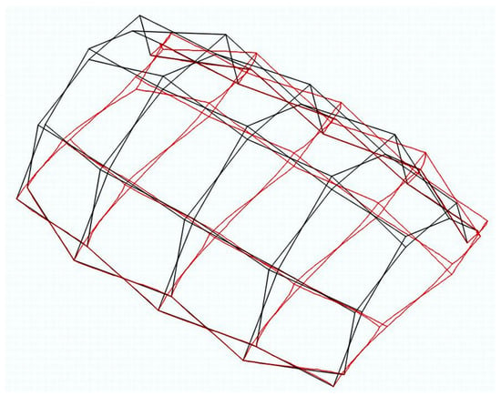
Figure 17.
Mesh deformation (×10).
5. Discussion
The effectiveness of reciprocal linkages has been demonstrated in the numerous tests carried out by our team. The objective of the current tests is to verify whether the loads on the articulated linkages in the lower layer of the structure and particularly the horizontal loads on the tympana represent an advantage that makes it advisable to build these structures with reciprocal linkages in their upper layer.
First, the small deviation of the results measured in the four tests carried out for each load hypothesis must be highlighted. Even in those cases in which the aforementioned buckling or oscillation phenomena are observed, they occur in the same way in all the tests.
In tests 1, 3 and 5, in which the loads are applied to the upper layer, the displacements are always smaller than in tests 2, 4 and 6 with loads applied to the lower layer. Considering the points of greatest displacement measured in each test, the loads in the lower layer increase the displacements between 33 and 54%, depending on the type of loads applied (Table 9).

Table 9.
Comparison of displacements according to the position of the loads.
However, comparing these results with those predicted in the theoretical models, it is observed that in all cases there is an improvement with respect to those of the structure with fully articulated joints. Calculations with reciprocal linkages involve displacements between 72% and 84% of those with articulated ones. If the experimental results are compared with the theoretical results of articulated joints, values between 75% and 82% are obtained.
The behavioural patterns regarding the opening and closing tendencies of the mesh depending on the situation and direction of the applied loads are maintained in all cases in the joints of the upper layer. In the joints of the lower layer, greater displacements are observed, caused because the load causes bending in the bars that are not restrained as their ends are articulated. The load on the upper reciprocating joints is always very favourable. On the contrary, the load in the lower layer causes high displacements that require larger sections. The results improve very considerably by having some additional bracing bars. At the moment, our team is studying this possibility with very promising results and we intend to present them in subsequent publications.
In all tests, oscillations are observed in the loading and unloading sections. They are small readjustment movements caused by the lack of rigidity of the linkages in the lower layer. However, once fully loaded, the structure stabilises quickly. In unloading, the structure initially retains a slight residual deformation, which asymptotically tends to zero quickly.
Particularly interesting are the results obtained in test 7, which corresponds to the action of horizontal loads in the longitudinal direction of the vault. If we consider that the bars are theoretically articulated at the linkages, this type of structure is a mechanism against horizontal actions, so the structure can be expected to collapse. In fact, the theoretical models considering this hypothesis, even taking into account the reciprocal support of the bars in the upper layer, foresee absolutely inadmissible displacements that exceed 2 m.
However, the experimental results do not agree with this approach. In fact, the measured results are quite compatible with those obtained in the calculation using the Rigid programme, which considers the structure with rigid joints with a degree of embedment that can be modified. The results of the theoretical model calculated through this programme with a degree of embedment of 80% are quite close to the experimental results. This suggests that the reciprocal support has a considerable capacity to stiffen the linkages even in the direction transverse to that of its movement. The conclusion is that these meshes have a structural behaviour for horizontal actions much higher than what could be deduced from theory, even without the need for auxiliary bracing elements.
It is important to highlight that the calculation models must take into account the necessary tolerance in the deployable structures to allow folding and unfolding movements. In the tested model, the diameter of the bolt is 4 mm, while the diameter of the bar hole is 4.2 mm, which determines a tolerance of 0.2 mm that is introduced as an initial displacement of the bars. Considering this effect, the displacements predicted in the calculation model show good agreement with those measured experimentally.
6. Conclusions
The results of the tests and theoretical calculations carried out show that, built with reciprocal linkages, these meshes improve their resistance performance in all cases, with respect to the same articulated linkage structures, whether the loads are applied in the lower layer or in the upper one.
In the case of loads applied to the lower layer, the displacements are always greater than when they are applied to the upper layer, since they act on articulated linkages. In all cases, the diagrams are practically linear in both loading and unloading, although some small oscillations already mentioned do occur. The residual deformation is always very low and is consistent with the readjustment of the structure considering the tolerance in the bar-linkage joints.
The results obtained confirm the validity of the calculation method used with regard to the central points of the vault, although they require caution with regard to certain edge points.
The degree of embedment caused by the reciprocal support is very high, exceeding 95%, both in the cylindrical section and in the conical ends. This reduces the deformations of the structure, although to a lesser extent than in the case of other meshes with reciprocal linkages in both layers, which have been analysed in previous publications.
Although only displacements can be measured on the test bench, it is confirmed that the behaviour of the structure is clearly linear in all cases. This allows the results to be compared with the theoretical models. Most of the maximum stresses calculated are between 20 and 30 MPa, with some specific cases of bars that can reach 142 MPa. In any case, these values are lower than the resistance capacity of the bars, which confirms that in this type of structure, the design limitations are imposed by the deformation and not by the stresses in the bars.
The case of the structure with horizontal loads in the longitudinal direction is especially notable, in which the measured displacements are much lower than those expected in a structure without bracing elements. The results of the theoretical calculation allow us to affirm that the reciprocal support allows a significant degree of embedment in the face of lateral loads, which can be estimated at 80%. The effectiveness of the reciprocal linkage against horizontal actions has been experimentally tested for this specific type of structure. The results have been better than expected, so in future research, we will try to analyse other types of deployable structures.
7. Patents
This study is part of the research project “Deployable and modular constructions for situations of humanitarian catastrophe”. The research carried out in this project has resulted in the patent cited in [24].
Author Contributions
Conceptualization: J.P.-V., M.M.-V., I.R.L.-C. and M.J.F.-T.; Methodology: J.P.-V., M.J.F.-T. and F.S.-R.; Software: J.P.-V., M.M.-V. and F.S.-R.; Formal analysis: J.P.-V., M.M.-V. and M.J.F.-T.; Construction of the model: J.P.-V., M.M.-V., I.R.L.-C. and M.J.F.-T.; Model testing: J.P.-V., M.M.-V., I.R.L.-C., M.J.F.-T. and F.S.-R.; Data processing: M.M.-V., M.J.F.-T. and F.S.-R.; Writing—review and editing: J.P.-V., M.M.-V., I.R.L.-C. and M.J.F.-T.; Supervision: J.P.-V., I.R.L.-C. and M.J.F.-T.; Project administration: J.P.-V.; Funding acquisitions: J.P.-V. All authors have read and agreed to the published version of the manuscript.
Funding
This study is part of the research project “Deployable and modular constructions for situations of humanitarian catastrophe”, funded by the Ministry of Economy and Competitiveness of the Kingdom of Spain with reference BIA2016-79459-R.
Data Availability Statement
Information on research project results can be downloaded at: https://www.codemosch.es/ (accessed on 13 May 2024).
Conflicts of Interest
The authors declare no conflicts of interest.
References
- Pérez-Valcárcel, J.; Muñoz-Vidal, M.; Freire-Tellado, M.; Gómez-Magide, D.; Casal-Rodríguez, A. Expandable bar structures for emergency situations. In Proceedings of the 4th International Conference on Structures & Architecture, Lisbon, Portugal, 24–26 July 2019; Structures and Architecture—Cruz (Ed.) © 2019. Taylor & Francis Group: London, UK, 2019; pp. 809–815. [Google Scholar]
- Pérez-Piñero, E. Estructura Reticular Estérea Plegable. Spanish Patent 26,6801, 15 September 1961. [Google Scholar]
- Pérez-Piñero, E. Estructures reticulées. L’Architecture D’aujourd’hui 1968, 141, 76–78. [Google Scholar]
- Pérez-Belda, E.; Pérez-Almagro, C. The deployable architecture commemorates the 25 years of peace. 50th Anniversary of Emilio Pérez Piñero’s Pavilion. EGA Expr.Gráfic. Arquit. 2016, 21, 146–155. [Google Scholar] [CrossRef][Green Version]
- Escrig, F.P.; Valcárcel, J.B. Estructuras espaciales desplegables curvas. Inf. Constr. 1988, 39, 53–71. [Google Scholar] [CrossRef]
- Escrig, F.; Pérez-Valcárcel, J. Deployable Cover on a Swimming Pool in Seville. Bull. Int. Assoc. Shell Spat. Struct. 1996, 37, 39–70. [Google Scholar]
- Gantes, C.J. Deployable Structures: Analysis and Design; WIT Press: Boston, MA, USA, 2001. [Google Scholar]
- Hernández, C.H. New Ideas on Deployable structures. In Mobile and Rapidly Assembling Structures II, Proceedings of the 2nd MARAS 1996, Seville, Spain, 17–20 June 1996; Brebbia, E., Ed.; Computational Mechanics Publications: Southampton, UK, 1996; pp. 63–72. [Google Scholar]
- Hernández, C.; Zalewski, W. Pabellón Itinerante de Exposiciones TaraTara; IDEC-FAU-UCV: Estado de Falcón, Venezuela, 2005. [Google Scholar]
- Sanchez-Cuenca, L. Stretch geometry for X-bar structures. Sci. Gerund. 1996, 22, 153–159. Available online: https://dialnet.unirioja.es/servlet/articulo?codigo=7396114 (accessed on 13 May 2024).
- Sánchez-Cuenca, L. Geometric models for expandable structures. Trans. Built. Environ. 1996, 21, 93–102. [Google Scholar] [CrossRef]
- Ponce, A.; Sánchez, J. Formal definition of the spatial deployable of rectangular module x-frames structures over frustoconical surfaces. In New Proposals for Transformable Architecture, Engineering and Design: In the Honor of Emilio Pérez Piñero, Proceedings of the First Conference Transformable 2013, Sevilla, Spain, 18 September 2013; Escrig, F., Sánchez, J., Eds.; Starbooks: Tokyo, Japan, 2013; pp. 59–61. [Google Scholar]
- García-Mora, C.J.; Sánchez-Sánchez, J. Geometric method to design bistable and non—Bistable deployable structures of straight scissors based on the convergence surface. Mech. Mach. Theory 2020, 146, 103720. [Google Scholar] [CrossRef]
- García-Mora, C.J.; Sánchez-Sánchez, J. Limitations in the design of deployable structures with straight scissors using identical elements. Int. J. Solids Struct. 2021, 230–231, 111171. [Google Scholar] [CrossRef]
- García-Mora, C.J.; Sánchez-Sánchez, J. Geometric strategies to design a bistable deployable structure with straight scissors using stiff and flexible rods. Int. J. Solids Struct. 2022, 238, 111381. [Google Scholar] [CrossRef]
- Freire Tellado, M.J.; Muñoz-Vidal, M.; Pérez-Valcárcel, J. Scissor-Hinged Deployable Structures Supported Perimetrally on Rectangular Bases. J. Int. Assoc. Shell Spat. Struct. 2020, 61, 158–172. [Google Scholar] [CrossRef]
- Gantes, C.; Konitopoulou, E. Geometric design of arbitrarily curved bi-stable deployable arches with discrete joint size. Int. J. Solids Struct. 2004, 41, 5517–5540. [Google Scholar] [CrossRef]
- Roovers, K.; De Temmerman, N. Deployable scissor grids consisting of translational units. Int. J. Solids Struct. 2017, 121, 45–61. [Google Scholar] [CrossRef]
- Arnouts, L.; Massart, T.; De Temmerman, N.; Berke, P. Computational design of bistable deployable scissor structures: Trends and challenges. J. Int. Assoc. Shell Spat. Struct. 2019, 60, 19–34. [Google Scholar] [CrossRef]
- Freire-Tellado, M.J.; Muñoz-Vidal, M.; Pérez-Valcárcel, J. Bias deployable grids with horizontal compound scissor-like elements: A geometric study of the folding/deployment process. Int. J. Space Struct. 2021, 37, 22–36. [Google Scholar] [CrossRef]
- Freire-Tellado, M.J.; Muñoz-Vidal, M.; Pérez-Valcárcel, J. Modified Bistable Modules for Bias Deployable Structures. Structures 2022, 36, 111–125. [Google Scholar] [CrossRef]
- Freire-Tellado, M.J.; Muñoz-Vidal, M.; Pérez-Valcárcel, J. Design of Diagonalised Square-Base Bistable Modules. Arab. J. Sci. Eng. 2023, 49, 5949–5971. [Google Scholar] [CrossRef]
- Pérez-Valcárcel, J.; Escrig, F.; Estévez, J.; Martín, E. Large Span Expandable Domes. In Proceedings of the International Conference on Large Span Structures, Toronto, ON, Canada, 13–17 July 1992; Volume 2, pp. 619–630. [Google Scholar]
- Pérez-Valcárcel, J.; Muñoz-Vidal, M.; Suárez-Riestra, F.; Freire-Tellado, M.; López-César, I.; Muñiz Gómez, S.; Aragón Fitera, J.; Mosquera Rey, E.; Hermo Sánchez, V. Deployable Structure, Building and Construction Method of a Building. Spanish Patent ES2757982B2, 7 July 2022. Available online: http://www.oepm.es/pdf/ES/0000/000/02/75/79/ES-2757982_B2.pdf (accessed on 13 May 2024).
- Pérez-Valcárcel, J.; Muñoz-Vidal, M.; López César, I.; Suárez-Riestra, F.; Freire-Tellado, M. A new system of deployable structures with reciprocal linkages for emergency buildings. J. Build. Eng. 2021, 33, 101609. [Google Scholar] [CrossRef]
- Pérez-Valcárcel, J.; Suárez-Riestra, F.; Muñoz-Vidal, M.; López-César, I.; Freire-Tellado, M.J. A new reciprocal linkage for expandable emergency structures. Structures 2020, 28, 2023–2033. [Google Scholar] [CrossRef]
- Pérez-Valcárcel, J.; Suárez-Riestra, F.; Muñoz-Vidal, M.; López-César, I.; Freire-Tellado, M.J. Deployable cylindrical vaults with reciprocal linkages for emergency buildings. Structures 2021, 33, 4461–4474. [Google Scholar] [CrossRef]
- Pérez-Valcárcel, J.; Muñoz-Vidal, M.; López César, I.; Suárez Riestra, F.; Freire Tellado, M. Deployable bundle modulus structures with reciprocal linkages for emergency buildings. Eng. Struct. 2021, 244, 112803. [Google Scholar] [CrossRef]
- Valcárcel, J.P.; Escrig, F.; Martín, E.; Domínguez, E.; Jaureguizar, F. Recent advances in analysis of expandable structures: An improved method. In Proceedings of the International Conference on Spatial Structures in New and Renovation Projects of Building and Construction IASS, Moscú, Russia, 22–26 June 1998; Volume 1, pp. 192–199. [Google Scholar]
- Muñoz-Vidal, M. RIGID 3.06 Program Structure Calculations for 3D Rigid and Semi-Rigid Joints; University of A Coruña: A Coruña, Spain, 2015. [Google Scholar] [CrossRef]
- Pérez-Valcárcel, J.; Muñoz-Vidal, M.; Freire Tellado, M.; López-César, I.; Suárez-Riestra, F. Expandable covers of skew modules for emergency buildings. Int. J. Innov. Eng. Sci. Res. 2020, 4, 38–52. Available online: https://www.ijiesr.com/e27.html (accessed on 13 May 2024).
- UNE-EN ISO 898-1:2000; Mechanical Properties of Fasteners Made of Carbon Steel and Alloy Steel. Part 1: Bolts, Screws and Studs (ISO 898-1:1999). UNE: Madrid, Spain, 2000.
Disclaimer/Publisher’s Note: The statements, opinions and data contained in all publications are solely those of the individual author(s) and contributor(s) and not of MDPI and/or the editor(s). MDPI and/or the editor(s) disclaim responsibility for any injury to people or property resulting from any ideas, methods, instructions or products referred to in the content. |
© 2024 by the authors. Licensee MDPI, Basel, Switzerland. This article is an open access article distributed under the terms and conditions of the Creative Commons Attribution (CC BY) license (https://creativecommons.org/licenses/by/4.0/).