Abstract
Internal combustion engines have been a major contributor to air pollution. Replacing these engines with electric propulsion systems presents significant challenges due to different countries’ needs and limitations. An active, purely mechanical solution to the problem of irregular torque production in an alternative internal combustion engine is proposed. This solution uses an actuator built on a camshaft and a spring, which stores and returns energy during the engine operating cycle, allowing torque production to be normalized, avoiding heavy flywheels. Designed for control throughout the engine’s duty cycle, this system incorporates a cam profile and a spring mechanism. The spring captures energy during the expansion stroke, which is then released to the engine during the intake and compression strokes. Simple, lightweight, and efficient, this system ensures smoother and more consistent engine operations. It presents a viable alternative to the heavy and problematic dual-mass flywheels that were introduced in the 1980s and are still in use. This innovative approach could significantly enhance the performance and reliability of alternative internal combustion engines without notable energy losses.
1. Introduction
1.1. Background
The internal combustion engine (ICE) exhibits inherent characteristics of torque fluctuations throughout its operational cycle. These fluctuations are a consequence of the engine’s mechanism, where the energy from fuel is converted into mechanical energy by discrete combustion events. Each combustion stroke generates a distinct torque impulse, contributing to an uneven torque output over the engine cycle. This phenomenon impacts the smoothness of engine operation and has broader implications for engine efficiency and longevity [1,2,3,4,5].
Historically, the engine industry has continually evolved to address these torque inconsistencies, driven by the pursuit of enhanced engine performance, smoothness, and efficiency. The traditional approach to mitigating torque variations has largely centered on passive mechanical solutions, such as the utilization of conventional flywheels and dual mass flywheels (DMF) [6]. However, while effective in smoothing out rotational speeds, the flywheel adds to the engine’s mass and is incapable of adjusting itself to the engine operation variations. On the other hand, the mechanism proposed in this study seeks to offer a relatively lightweight solution that harmonizes the produced torque without affecting the engine’s capability for acceleration or deceleration. This initiative is part of a broader research endeavor aimed at studying and developing a mechanism capable of functioning across all engine speed ranges and under various loads. Currently, the focus is on enhancing performance during idle and low-speed operations, where the demand for such systems is most critical [2,7].
Recent advancements employing mechanical, electromechanical, and control strategies have significantly improved torque harmonization and reduced engine vibrations and rotational speed variations. This serves as a clear indication of both the opportunity and the need for further advancements in this domain, emphasizing the shift away from traditional, bulkier, and less efficient solutions towards more accurate and responsive technologies. Moreover, this transition facilitates the integration of engines into hybrid vehicles, range extenders, and microcogeneration systems [8,9,10,11,12,13].
This study builds upon approaches introduced by Lin et al. [14] and Arakelian et al. [15]. Although the first study focuses on reducing torque variations in the camshaft and the second emphasizes inertia effects in slider-crank mechanisms, both studies commonly utilize a cam to control the mitigating mechanism and a spring to act as energy storage. Another approach, conducted by Cardoso and Fael [16], has demonstrated the feasibility of using switched reluctance machines to replace traditional flywheels, offering a method to correct engine output torque and speed variations, albeit at the cost of a complex system. Despite these advancements, a gap remains in seamlessly integrating these technologies into existing engine designs without complex control systems or significant modifications to the engine architecture. This research aims to fill this gap by developing a mechanically focused solution that maintains engine performance, particularly at low rotational speeds.
1.2. Problem Statement
A series of multifaceted challenges underscore the quest to enhance torque management in internal combustion engines. At the core of these challenges lies the inherent nature of alternative ICE operations, where the intermittent combustion process leads to nonuniform torque output. This irregularity manifests as torque ripple or fluctuations, which not only compromises the smoothness and responsiveness of the engine but also adversely affects overall efficiency and increases vibrations and noise [17,18].
One of the primary issues in contemporary torque management is the limitation of traditional mechanical solutions. While these methods, such as the utilization of flywheels, have been fundamental in maintaining engine operation at low speeds, they fall short of addressing the demands of modern engines. The added mass and inertia of traditional solutions often impede the engine’s dynamic response, failing to align with the growing emphasis on lightweight and compact engine designs. Moreover, these approaches do not actively adapt to varying operational conditions, thus limiting their effectiveness in dynamic and diverse operation scenarios [19,20,21].
Another critical aspect is the evolution of engine technology itself, with advancements in engine design, including the trend towards more compact, lightweight engine designs, different cylinder arrangements, unusual cylinder number engines (this can lead to extreme torque production irregularities), cylinder deactivation technologies, and the advent of hybrid and electric vehicles, highlighting the need for systems that offer greater precision and adaptability [22,23,24,25,26,27].
1.3. Objectives
Study of Torque Decomposition in a Slider Crank Engine: The objective pretends to study the decomposition of output torque in an alternative engine design. This involves analyzing how different torque types (such as driving torque, resistive torque, and mass inertia torque) contribute to the overall output torque in this kind of engine.
Development of a Camshaft: The main objective of this research is to design and develop a camshaft, which is the main component of the actuator implemented to smooth the torque output. The key challenge is in creating a cam profile that can precisely mimic the torque output profile and can act on the spring, compressing it to store mechanical energy during the expansion stroke and subsequently receiving energy from the spring to return it to the engine during strokes when the engine is not producing positive work.
Development of an Integrated Camshaft-Actuator System: With this objective, an integrated system controlled by the developed cam is intended to be designed and developed. In this process, some considerations must be taken, with some of the most important parts to study and develop being the spring stiffness and preload. The spring needs to be studied to store as much energy as possible without interfering with the engine’s natural movement and performance.
Evaluation and Demonstration of System Adaptability and Performance: Lastly, the evaluation of the performance of the developed system during idle operation is aimed at.
1.4. Study Contributions
The major contributions of this work are divided between the development of a mechanical mechanism and advancements in the field of internal combustion engines. The specific contributions of this study are outlined as follows:
Advanced Torque Decomposition Analysis: A comprehensive analysis of torque decomposition in alternative engines is provided. This approach enhances understanding of how different types of torque—driving, resistive, and mass inertia—interact and contribute to overall engine performance. This insight is useful for future work, for example, focusing on studying engine torque output smoothness and examining how geometric and construction parameters influence torque production.
Camshaft Development Methodology: This work includes the design and development of a camshaft that accurately replicates the engine’s torque output profile. The design process encounters challenges due to the irregularities of the engine’s torque output and the numerous parameters influencing the cam’s profile. This paper presents a methodology for cam development.
Development of a Torque Mitigating Mechanism: This study introduces the development of a fully mechanical torque mitigating mechanism. The mechanism is designed to absorb excess energy from the engine system during periods of high output and strategically release it during phases where additional energy is required. This cyclic absorption and redistribution are tailored to operate seamlessly across different periods of time and varying operational conditions.
Integration of a Camshaft-Actuator with a single-cylinder engine: Beyond individual components, this study focuses on integrating the developed mechanism, which includes a camshaft for control and a spring for energy storage, with a single-cylinder engine. This integration aims to enhance torque smoothness and ensure that speed variations during the engine cycle remain closely aligned with the engine’s average rotational speed.
2. Engine Torque Analysis
In considering the output torque at the crankshaft of ICEs, as illustrated in Figure 1, torque fluctuation arises mainly from three sources. Firstly, the driving torque generated mostly during the expansion stroke in ICEs leads to irregular driving actuation. This fluctuation is consistent across different crankshaft speeds, depending solely on crankshaft angle (φ) and pressure force (Fpressure). Secondly, fluctuation occurs due to the inertia force from the acceleration (α) of the imbalanced mass. This type of fluctuation is more pronounced at higher speeds as it is proportional to the square of the engine’s angular speed (). Lastly, fluctuating resistive loads, such as those in engine valve systems, impart irregular torque to the camshaft, independent of engine angular speed and related to crankshaft angle [14], [28,29].
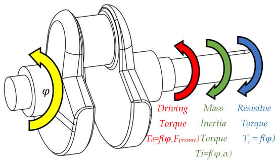
Figure 1.
Representation of how the three types of torque mentioned above act on the crankshaft.
To mitigate these fluctuations, passive and active techniques have been employed. Flywheels, as referred to previously, for example, can store and release kinetic energy to smooth out speed fluctuations but are less effective at low speeds due to their large inertia. This affects the engine performance and its capacity to change the rotational speed when solicited and the use of this represents an expressive mass increment. Torsional vibration dampers offer a solution across various speeds, but this involves dissipation of energy. Active control techniques, in contrast, counteract torque fluctuations by providing an opposing force, but at the cost of complex control techniques or input of external energy [30,31].
For a clearer understanding of the torque production cycle in internal combustion engines, the analysis is often conducted using a single-cylinder engine model. This approach effectively isolates three types of torque fluctuations, which are more difficult to discern in multicylinder engines due to the overlapping of multiple-stroke events.
These events significantly contribute to torque fluctuations and can be categorized into two groups: those that generate positive torque and those that produce negative torque. Only the expansion that represents a quarter (on Otto) of the strokes and is part of the first group is directly useful for the engine’s primary purpose. However, the magnitude of this useful stroke at engine full load is about fifteen times greater than the average of the other three strokes. However, despite their negative torque, strokes such as intake, compression, and exhaust are essential for the engine’s cycle.
The torque generated by an engine is a composite of the three types of torque previously described, as outlined in Equation (1). The capability of alternative engines to generate torque stems from the slider−crank mechanism, depicted in Figure 2. Through dynamic analysis of this mechanism, both the inertia torque and driving torque of the engine can be accurately determined.
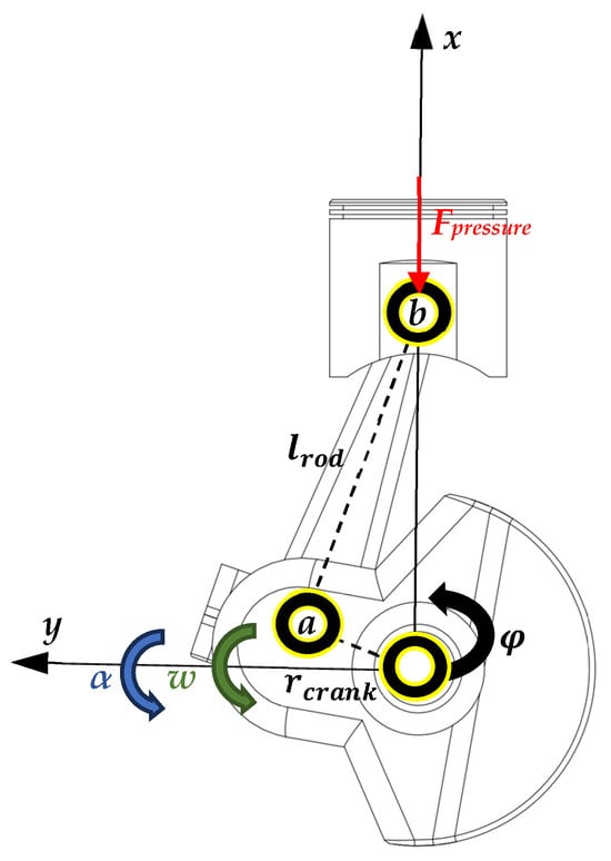
Figure 2.
Slider−crank mechanism from a single-cylinder engine.
2.1. Driving Torque
ICEs are volumetric machines designed to convert the chemical energy in fuel into mechanical energy, which is then transferred to the crankshaft. They utilize a slider−crank mechanism to convert pressure variations from fuel combustion in the combustion chamber into mechanical movement. This is due to the design of the alternative engine that only allows the gases in the cylinder to expand in the piston direction.
The force resulting from these pressure variations can be expressed as the product of the cylinder’s internal pressure by the piston area, as shown in Equation (2). This equation clearly illustrates the generation of driving force in ICEs due to pressure variation, calculated from Equation (3), determined using the first law of thermodynamics.
For a comparative analysis, Figure 3 demonstrates how the values of pressure exerted in the piston can act in the piston when the engine is running at idle, i.e., when the engine only produces the torque needed to keep it running and when the presence of the flywheel is most necessary to store energy from the expansion stroke for the rest of the strokes. In contrast, Figure 4, derived from an analysis based on Figure 2, culminating in Equation (4), depicts the generation of driving torque throughout a 720° crankshaft rotation in an Otto engine under identical operational conditions to those shown in Figure 3 [32].
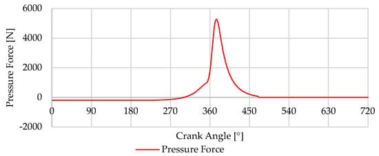
Figure 3.
in the piston from Otto strokes.
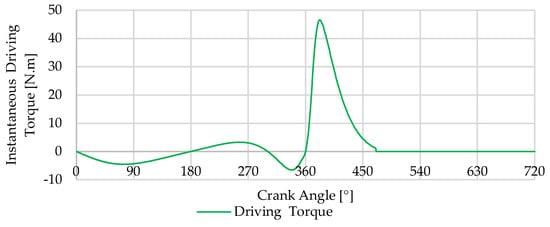
Figure 4.
Driving torque from the on the slider−crank mechanism.
2.2. Mass Inertia Torque
Mass inertia torque, hereinafter referred to as inertia torque, arises from the moving parts, particularly during changes in their speed. In the context of an ICE, this involves components like the crankshaft, connecting rods, pistons, and other moving parts. The inertia of these components plays a significant role in the engine’s responsiveness, vibrations, and overall performance. Inertia torque is influenced by several factors, including the mass and distribution of the engine’s moving parts and the speed. The faster the components rotate, the more significant the inertia torque becomes, as it takes more force to change the speed of these rapidly moving parts. This phenomenon is especially noticeable during rapid acceleration or deceleration, where the inertia torque can have a substantial impact on engine performance. The inertia forces can be broken down into components along the piston’s movement line (x-axis), which induce forces on the crankshaft and thereby contribute to its torque, presented in Equation (5), and forces acting perpendicularly to the former (y-axis), which do not directly affect the torque generated by the engine, presented in Equation (6). The mass responsible for inducing inertia forces includes the mass of the piston group and the connecting rod. For simplification purposes, this mass is divided between two distinct points: point a, located on the crankshaft pin (as shown in Figure 2), where, according to literature, we can consider as comprising 2/3 of the connecting rod mass, and point b, located on the piston pin, where the piston group mass and 1/3 of the connecting rod mass are assumed, as outlined in Equations (7) and (8) [33].
To calculate the torque induced by inertia forces on the crankshaft, as detailed in Equation (9), consideration is given only to the masses previously divided and located at point b. This approach is based on the premise that the crankshaft is properly balanced, factoring in the masses on the crankshaft pin and the equivalent connecting rod mass at the point a, ensuring that the rotational balance point of this mass aligns with the crankshaft’s center of rotation.
Figure 5 represents the forces that lead to the torque profile obtained in Figure 6. For clarity, green vertical lines indicate the top dead center and blue vertical lines denote the bottom dead center. Figure 6 illustrates the magnitude of the inertia torque produced by the movement of the internal components in a single-cylinder slider crank engine model at 800 RPM without charge, representing idling operation.
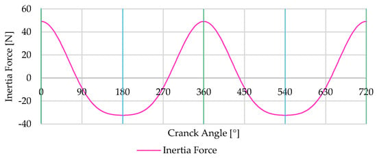
Figure 5.
Inertia forces on the crankshaft at 800 RPM from the piston group and connecting rod.
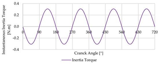
Figure 6.
Instantaneous inertia torque on the crankshaft from internal components in a single-cylinder slider−crank engine.
2.3. Resistive Torque
The resistive torque comes essentially from camshafts, oil pumps, or other engine auxiliary elements. This torque type is primarily due to resistive forces that the engine components must overcome during operation. For the purposes of this work, only the resistive torque from camshafts will be considered. In the context of camshafts, this type of torque fluctuates based on the engine cycle, particularly in the valve operation phase, where the opening and closing of valves require varying levels of force. In the camshaft context, the resistive torque is a consequence of the need to compress (negative torque) and then release (resulting in positive torque) the valve springs. The magnitude of this torque fluctuation can vary significantly based on the springs’ stiffness and the valve mechanism’s design. At lower to medium speeds, the resistive torque fluctuation tends to be more substantial than the inertia torque fluctuation. To quantitatively analyze resistive torque in ICEs, one must consider the spring stiffness, the preload force, the rocker mechanism, and the displacement of valves (see Figure 7 and Figure 8). The spring force from the valve mechanism can be expressed by Equation (10) [34].
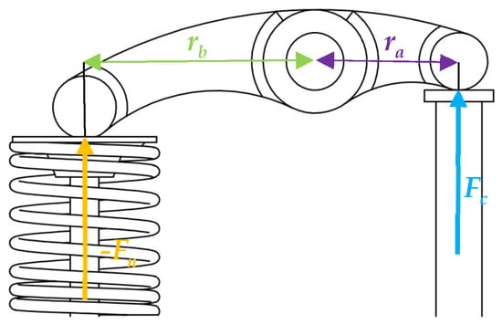
Figure 7.
Rocker arm diagram from the valve train.
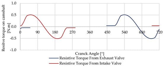
Figure 8.
Resistive torque from intake and exhaust valve mechanism.
3. Design of the Torque Correction Mechanism
3.1. Design Concept
To enhance the output torque’s smoothness, a specifically engineered mechanism is proposed to create a counteracting torque. This design pretends to minimize fluctuations in the engine’s output torque. Key components of this system include a spring for energy storage and a cam tailored to align with the engine’s output torque characteristics. A CAD model of this mechanism is shown in Figure 9. The mechanism is structured to generate a counteracting torque at any rotation angle θ, matching the output torque in magnitude but opposite in direction.
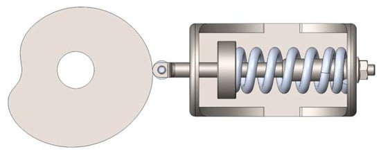
Figure 9.
CAD model from the mechanism, with the cam designed to mimic the profile torque desire, the roller follower, and the spring responsible for storing the energy.
To achieve the desired mechanism response, the specially designed cam must replicate the engine’s opposing torque. It can be installed on the camshaft or with a 2:1 transmission ratio, similar to the engine’s distribution system, which may increase friction and consequently, resistive torque, leading to a more complex system. This is due to the torque contributing events being dispersed over the 720° crankshaft rotation in a 4-stroke cycle. The direct integration of this mechanism into the crankshaft would simplify implementation but is impractical for addressing resistive and driving torque irregularities, though it would be effective for inertia torque, as shown in Figure 6 with its 360° periodicity. Figure 10, Figure 11 and Figure 12 illustrate a potential implementation in a single-cylinder engine using the existing distribution system and camshaft to simplify the system and minimize friction. This implementation assumes available space on the camshaft for the cam and that the camshaft shaft and transmission ratio can support the counteracting torque with these premises being valid for a demonstrative implementation in this specific engine construction.
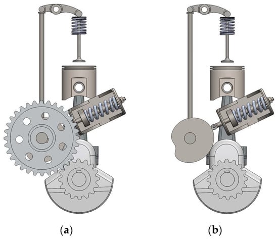
Figure 10.
Front views of the CAD model from the (a) mechanism integrated on the single-cylinder engine, on image (b) the camshaft gear was removed to show the positioning of the balancing cam.
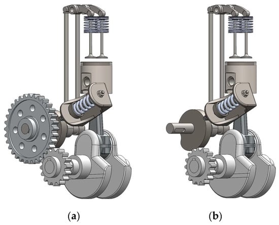
Figure 11.
Perspective views—left side—of the CAD model from the (a) mechanism integrated on the single-cylinder engine, in image (b), the camshaft gear was removed to show the positioning of the balancing cam.
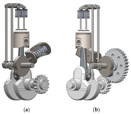
Figure 12.
Perspective views—right side—of the CAD model from the (a) mechanism integrated on the single-cylinder engine, in image (b), the camshaft gear was removed to show the positioning of the balancing cam.
3.2. Determination of the Balancing Cam Profile
The cam’s profile is essential for controlling the actuator in response to the engine’s needs. This cam was developed by considering the torque acting upon it, which is then transformed and stored in the spring. To design the cam profile, it is required to determine the cam radius in the function of the crankshaft rotation angle , for a previously defined torque profile. Figure 13 is a diagram of the forces acting on the cam [14,33,34].
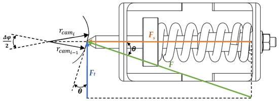
Figure 13.
Diagram of the mechanism used to deduce the equations that allow the balancing cam to be obtained that mimics the desired torque profile.
The torque on the mechanism camshaft as the product of the tangential force by cam radius:
From Figure 13 is the product from the by the as presented in Equation (14), and can be directly substituted into Equation (13), which gives the torque as a function of as presented in Equation (15), depends on the spring conditions and the displacement induced by the cam on the spring, as shown by Equation (16).
Based on the defined torque for the cam , can be determined using Equation (17). Then, following Equation (18), which arises from the analysis of the diagram in Figure 13, the radius of the cam can be calculated as a function of the crankshaft angle.
To convert the previously obtained polar coordinates into cartesian coordinates for better visualization and plotting of the cam, Equations (19) and (20) are used.
Finally, when integrating a roller follower, including the roller’s radius in the cam profile calculation is necessary. This is done using Equations (21) and (22), ensuring the cam profile meets all specified conditions for the roller follower. This crucial step guarantees that the cam design is effectively customized for the specific follower type in the engine mechanism.
4. Modelling of Torque Correction Mechanism
4.1. Engine Modelling and Simulation
The development of the engine simulation, performed using MATLAB® R2024a (MathWorks, Natick, MA, USA), is based on a modeling approach that analyzes the engine’s instantaneous torque for each degree of crankshaft rotation. It was specifically constructed to dissect engine torque into three distinct components.
The simulation inputs geometric parameters to model the slider−crank mechanism, iterating through one-degree increments of crankshaft rotation. It spans 720 degrees of rotation to simulate, among other things, torque values and speed variations at each degree, covering a full cycle of the 4-stroke engine under study.
As shown in Section 2 through various graphs, this modeling framework successfully segments engine torque into three main components: the inertia torque driven by mass acceleration, as specified in Equation (9); torque due to pressure differences within the engine cylinder, detailed in Equation (3); and the resistive torque produced by the valve mechanism, outlined in Equation (12).
The engine parameters are outlined in Table 1. The simulation framework is organized around valve timing, divided into four segments that correspond to each stroke of the Otto cycle, thereby covering all necessary conditions to derive operational parameters at each crankshaft angle, as will be analyzed in Section 4.3.

Table 1.
Engine parameters used to perform the simulation used to present the idle torque profile.
This simulation incorporates elements that yield instantaneous torque curves closely resembling those obtained through experimental means. Figure 14 showcases the results from prior experimental work conducted to validate the curves derived from the implemented methodology [3].
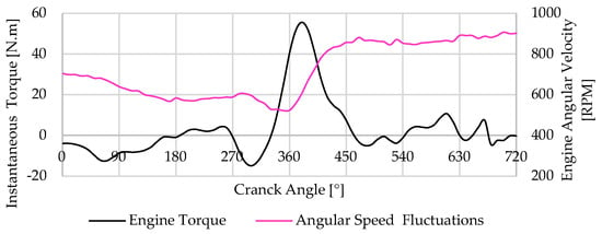
Figure 14.
Experimental output torque from the single-cylinder engine at idle, 800 RPM.
4.2. Balancing Cam Mechanism Modelling
For the torque correction mechanism’s development, a torque profile established from the process described earlier is used. The mechanism and cam, crafted based on equations detailed in Section 3.2, aim to correct the torque profile illustrated in Figure 15, which represents an engine idle at 800 RPM. In defining the cam profile, in addition to the torque profile, the input parameters are the spring’s stiffness , spring preload , initial cam radius and if the mechanism uses a roller follower like the one shown in the CAD representations of the mechanism ; These parameters are outlined in Table 2.
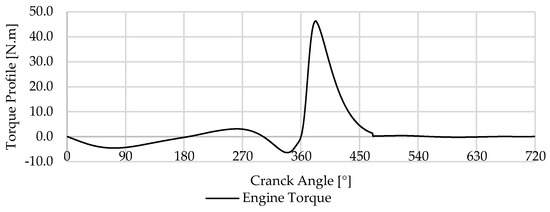
Figure 15.
Output torque from single-cylinder engine during idle at 800 RPM, used to design the cam profile.

Table 2.
Balancing mechanism parameters.
Based on the torque profile outlined, the cam shown in Figure 15 was developed through an iterative process involving the parameters in Table 2 and the torque profile in Figure 15, which shows two cam profiles, one for a follower with and one without a roller. The desired cam profile aimed to maintain a radius not exceeding 50 mm for integration purposes in the specified engine. In Figure 16, the cam analysis shows three distinct zones. Section 1, in the first quadrant, shows the beginning of a cam profile depression, signifying energy release from the spring to the crankshaft, countering the resistive torque during valve opening, and the driving torque of the air-fuel mixture intake. Section 2 highlights a marked decrease in cam radius, associated with compensating the compression process of the air−fuel mixture, with a sharp radius increase towards the end of compression and the start of the expansion. This radius increase continues during the third quadrant, storing energy in the spring from the expansion to utilize during the other strokes. Section 3, located in the fourth quadrant, mirrors the analysis of Section 1, about the exhaust process. Additionally, in Figure 16, a perfect circumference is depicted by a red dotted line, allowing for a comparison between the cam profile variations and a perfect circle profile.
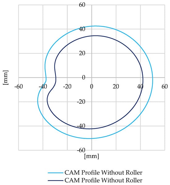
Figure 16.
Representation of the determined CAM profile if the follower is with roller or without, considering the torque profile presented previously.
Building upon the previously described cam and maintaining the parameters used for its design, the torque returned by the mechanism to the engine is illustrated in Figure 17. Figure 18 shows the torque delivered from the mechanism into the crankshaft.
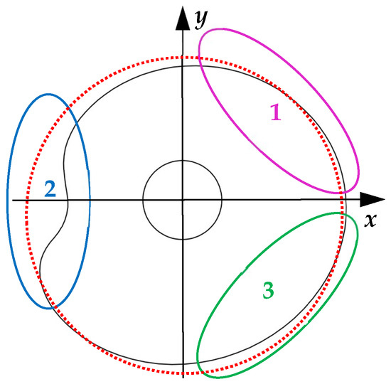
Figure 17.
Esquematization of the determined CAM profile, considering the torque profile presented previously.
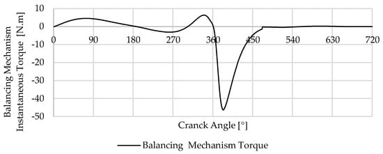
Figure 18.
Torque delivered from the mechanism into the crankshaft.
4.3. Balancing Cam Mechanism Integration with the Engine
The integration of the balancing cam mechanism with the engine simulation, as established in Section 4.1 and Section 4.2, is detailed in the processes outlined in Figure 19, the flowchart representing the simulation steps. The simulation begins by setting the engine’s geometric parameters, initial conditions, and the cam profile for the balancing cam mechanism. The flowchart in Figure 19 tracks the engine cycle through each crank angle from 0 to 720 degrees, covering one complete cycle of a four-stroke engine. This encompasses all phases of engine operation: intake, compression, combustion, expansion, and exhaust. During each phase, the simulation calculates various parameters, such as temperatures and pressures within each stroke. These values are crucial for determining the torque and angular speed in each phase. The torque and angular speed calculated by the simulation are then refined by the balancing cam mechanism. This mechanism uses a predefined cam profile and spring parameters to compute the output torque from the mechanism and adjust the engine’s simulated torque based on the established initial conditions.
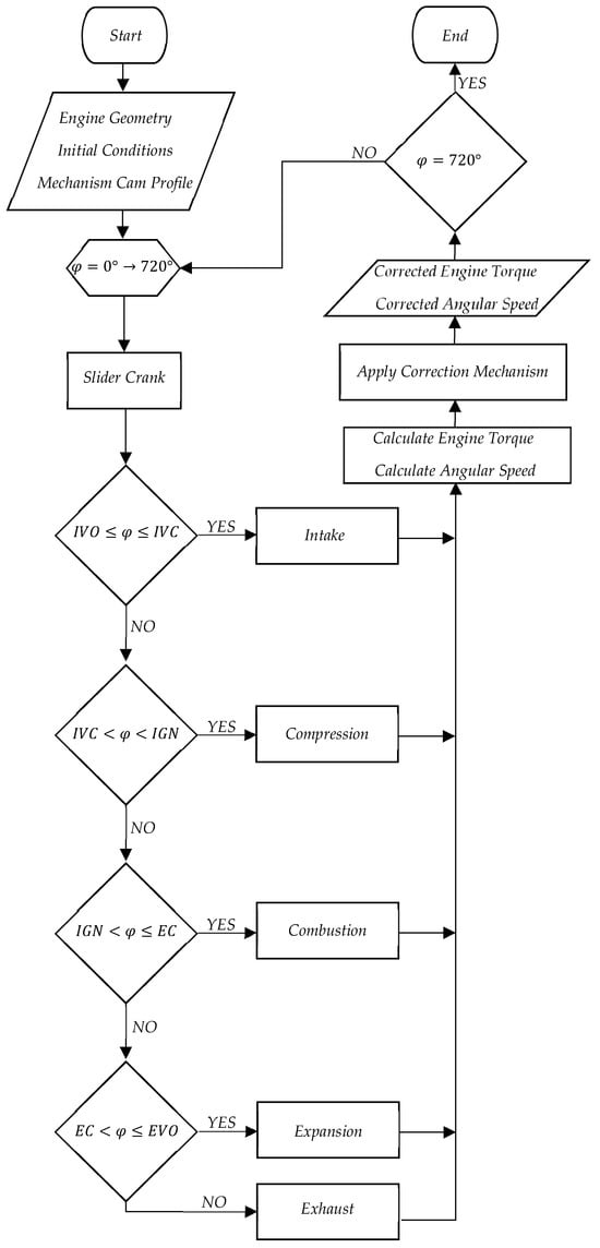
Figure 19.
Simulation Flowchart.
The corrections made to the engine torque and angular speed by this integration represent the outputs the simulation aims to achieve. The simulation cycle is documented until the crank angle reaches 720 degrees, marking the end of one full engine cycle.
4.4. Simulation Results
The simulations were performed to analyze and determine the distinct characteristics of driving torque, resistive torque, and inertia torque within an internal combustion engine. These types of torque, which have been previously discussed individually, are now collectively examined in Figure 20. This Figure illustrates the engine’s output torque profile under the simultaneous influence of driving, resistive, and inertia torque. This comprehensive analysis is crucial as it reveals how the combined effects of these different torques impact the overall performance of the engine. Particularly noteworthy in this idle scenario is that the three types, the torque resulting from the valve mechanism, the inertia of the engine’s internal components, and driving torque during intake and exhaust, contribute to the same magnitude for the final engine torque. The variations in engine torque in these conditions are observed during the moments when the piston reaches its extreme positions—the bottom dead center and the top dead center. At these junctures, the piston experiences significant accelerations and decelerations, which in turn influence the directional reversal of its motion. Other variations outcomes from the operation of opening and closing the intake valve approximability from 0 to 180° and the exhaust valve from 540 to 720°, the most pronounced fluctuations from to 180 540° come from the compression and expansion process.
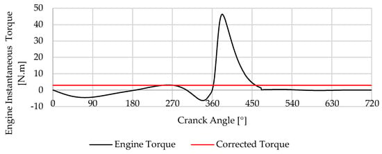
Figure 20.
Profile of the engine output torque with the mechanism in red and without the mechanism in black.
In Figure 20, it is possible to observe the overlay of two torque profiles—one from the engine and the other from the mechanism. The computational results assume a loss-free system, indicating that the torque resulting from the system implementation is a consistent profile. This supports the thesis presented, validating the effectiveness of the implemented system in maintaining a stable torque during idle operation.
Torque variations result in corresponding changes in engine speed, which are more noticeable in idle regimes due to the lack of load masking these variations. Figure 21 demonstrates the engine speed variations over a cycle, consistent with the previously analyzed torque variations. As the mechanism suppresses torque fluctuations, it directly impacts reducing speed variations, consequently decreasing vibrations and noise.
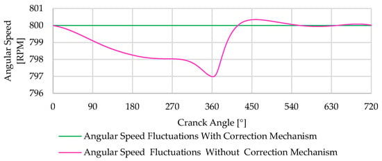
Figure 21.
Angular speed variation over the cycle.
4.5. Limitations and Future Work
The need for an energy storage system in ICEs, such as the traditionally used flywheel or the system presented in this work, is more pronounced during low-speed operations or idling. The system developed and designed in this research is specifically tailored to function when the engine is idling. However, as the load imposed on the engine or its rotational speed increases, the influence of this mechanism is lower. To address this limitation, ongoing research efforts are focused on designing a system that can adapt the mechanism to the engine by varying the spring preload based on the engine load and rotation. This adaptation aims to make the system more influential in smoothing the engine’s output torque. The development of this system faces several challenges. One significant challenge is that as the engine’s rotation speed or load increases, variations primarily occur in the driving torque and inertia torque; consequently, increasing the spring’s preload to accommodate these changes can inadvertently amplify the resistive torque correction component from the mechanism, which does not vary under the conditions. This increase in resistive torque, due to the higher preload of the spring, may introduce irregularities in the engine’s output torque. Future work will focus on overcoming these challenges by refining the developed cam and the mechanism to balance the varying torque components effectively.
5. Conclusions
This paper introduced a balancing mechanism designed to smooth the output torque of the engine. The torque model proposed for the engine revealed that output torque fluctuations result from a combination of multiple factors, each contributing differently to the final torque produced by the engine. By employing a balancing mechanism with a specifically designed cam profile, the engine operation can be smoothed during idle periods without relying on traditional and heavy flywheels.
The simulations conducted in Section 4 allowed us to study the influence of various factors on engine torque and their actual impact on engine torque. Variations in torque production reflect speed changes throughout the engine cycle, which are responsible for generating vibrations. By developing a system capable of addressing these vibrations, engine operation cannot only be stabilized but also reduce engine mass and the need for energy absorbing dampers.
Although this system does not significantly influence high-speed engine operation, it does not introduce irregularities in the engine’s normal functioning. It proves to be an effective solution for correcting engine operation during idling and opens opportunities for developing a system capable of adapting to different engine operating regimes.
Evaluating the performance of our novel mechanism alongside traditional systems like heavy flywheels, we observed notable differences. While flywheels serve well in specific conditions, they do not offer the necessary adaptability and tend to increase the overall weight of the engine system, and inclusively change the engine behavior. On the other hand, our mechanism has the potential to adjust dynamically to meet operational demands and efficiently smooth torque fluctuations with much less impact on engine weight and behavior.
The preliminary results obtained align with those presented in similar studies, albeit for different purposes, such as those by Lin et al. [14] and Arakelian et al. [15], which employ the use of cam-based mechanisms for torque correction. These findings reinforce the validity of our approach and highlight the versatility of cam mechanisms in various engineering applications beyond their traditional uses. By leveraging cam-based designs, we can achieve a consistent correction of torque fluctuations, which is critical for enhancing the operational stability and efficiency of internal combustion engines; this convergence of results across different studies underscores the potential of our proposed mechanism.
This study introduces a unique mechanism for torque harmonization that meets the current and emerging needs of modern engines, emphasizing efficiency and adaptability. Such advancements are instrumental in the development of new technologies, including range extenders, microcogeneration systems, and innovative engine configurations, representing a substantial progression in engine technology.
6. Patents
This and subsequent works resulted in a patent application submitted to the Portuguese Institute of Industrial Property (INPI) under application number 119346, with the title “Método Implementado por Computador para a Conceção de um Atuador de Equilíbrio para um Motor, Atuador de Equilíbrio, Programa de Computador e Meio de Leitura Associados”.
Author Contributions
Conceptualization, D.S.C. and P.O.F.; methodology, D.S.C. and P.O.F.; software, D.S.C. and P.O.F.; validation, P.O.F., P.D.G. and A.E.-S.; formal analysis, P.O.F., P.D.G. and A.E.-S.; investigation, D.S.C. and P.O.F.; data curation, P.O.F.; writing—original draft preparation, D.S.C.; writing—review and editing, D.S.C., P.O.F. and P.D.G.; supervision, P.O.F., P.D.G. and A.E.-S. All authors have read and agreed to the published version of the manuscript.
Funding
This research was funded in part by the Fundação para a Ciência e Tecnologia (FCT) and C-MAST (Centre for Mechanical and Aerospace Science and Technologies) for their support in the form of funding under the project UIDB/00151/2020 (https://doi.org/10.54499/UIDB/00151/2020; https://doi.org/10.54499/UIDP/00151/2020, accessed on 3 January 2024).
Data Availability Statement
Data are contained within the article.
Acknowledgments
We would like to express our gratitude to the Entrepreneurship, Careers, and Alumni Office (GESPA) at the University of Beira Interior for facilitating our collaboration with a company specializing in patent development. We are also thankful to Susana Rodrigues from Inventa, who expertly guided us through the process of writing the patent application.
Conflicts of Interest
The authors declare no conflicts of interest.
References
- Solmaz, H.; Karabulut, H. A mathematical model to investigate the effects of misfire and cyclic variations on crankshaft speed fluctuations in internal combustion engines. J. Mech. Sci. Technol. 2015, 29, 1493–1500. [Google Scholar] [CrossRef]
- Babagiray, M.; Solmaz, H.; İpci, D.; Aksoy, F. Modeling and validation of crankshaft speed fluctuations of a single-cylinder four-stroke diesel engine. Proc. Inst. Mech. Eng. Part D J. Automob. Eng. 2022, 236, 553–568. [Google Scholar] [CrossRef]
- Cardoso, D.S.; Fael, P.O.; Espírito-Santo, A. Instantaneous angular velocity and torque on Otto single-cylinder engine: A theoretical and experimental analysis. Energy Rep. 2020, 6, 43–48. [Google Scholar] [CrossRef]
- Filipi, Z.S.; Assanis, D.N. A nonlinear, transient, single-cylinder diesel engine simulation for predictions of instantaneous engine speed and torque. J. Eng. Gas Turbines Power 2001, 123, 951–959. [Google Scholar] [CrossRef]
- Antonopoulos, A.K.; Hountalas, D.T. Effect of instantaneous rotational speed on the analysis of measured diesel engine cylinder pressure data. Energy Convers. Manag. 2012, 60, 87–95. [Google Scholar] [CrossRef]
- Munde, K.H.; Mehtre, V.K.; Ware, D.S.; Kamble, D.P. Review on Performance of Dual Mass Flywheel over Conventional Flywheel. Math. Stat. Eng. Appl. 2022, 71, 496–505. [Google Scholar] [CrossRef]
- Dawange, S.V.; Kadlag, V.L. A Review Paper on Vibration Analysis of DI Engine. Int. J. Sci. Res. IJSR 2015, 4, 759–761. [Google Scholar]
- Cardoso, D.; Nunes, D.; Faria, J.; Fael, P.; Gaspar, P.D. Intelligent Micro-Cogeneration Systems for Residential Grids: A Sustainable Solution for Efficient Energy Management. Energies 2023, 16, 5215. [Google Scholar] [CrossRef]
- Mittal, V.; Shah, R.; Przyborowski, A. Analyzing the Usage of Wankel Engine Technology in Future Automotive Powertrains. SAE Int. J. Sustain. Transp. Energy Environ. Policy 2023, 5, 1–13. [Google Scholar] [CrossRef]
- Schaper, U.; Sawodny, O.; Mahl, T.; Blessing, U. Modeling and torque estimation of an automotive Dual Mass Flywheel. In Proceedings of the 2009 American Control Conference, St. Louis, MO, USA, 10–12 June 2009; pp. 1207–1212. [Google Scholar] [CrossRef]
- Ayana, E.; Plahn, P.; Wejrzanowski, K.; Mohan, N. Active torque cancellation for transmitted vibration reduction of low cylinder count engines. IEEE Trans. Veh. Technol. 2011, 60, 2971–2977. [Google Scholar] [CrossRef]
- Anjum, R.; Yar, A.; Ahmed, Q.; Bhatti, A. Model-Based Unified Framework for Detection and Mitigation of Cyclic Torque Imbalance in a Gasoline Engine. J. Eng. Gas Turbines Power 2021, 143, 071013. [Google Scholar] [CrossRef]
- Zhang, X.; Liu, H.; Zhan, Z.; Wu, Y.; Zhang, W.; Taha, M.; Yan, P. Modelling and Active Damping of Engine Torque Ripple in a Power-Split Hybrid Electric Vehicle. Control Eng. Pract. 2020, 104, 104634. [Google Scholar] [CrossRef]
- Lin, D.Y.; Hou, B.J.; Lan, C.C. A balancing cam mechanism for minimizing the torque fluctuation of engine camshafts. Mech. Mach. Theory 2017, 108, 160–175. [Google Scholar] [CrossRef]
- Arakelian, V.V.; Briot, S. Simultaneous inertia force/moment balancing and torque compensation of slider-crank mechanisms. Mech. Res. Commun. 2010, 37, 265–269. [Google Scholar] [CrossRef]
- Cardoso, D.S.; Fael, P.O. Simulation and analysis of a switched reluctance machine for flywheel replacement. In Lecture Notes in Engineering and Computer Science, Proceedings of the World Congress on Engineering 2018, London, UK, 4–6 July 2018; Springer: Singapore, 2019; pp. 819–823. [Google Scholar] [CrossRef]
- Kim, G.W.; Shin, S.C. Research on the torque transmissibility of the passive torsional vibration isolator in an automotive clutch damper. Proc. Inst. Mech. Eng. Part D J. Automob. Eng. 2015, 229, 1840–1847. [Google Scholar] [CrossRef]
- Vehicular Technology Society; Institute of Electrical and Electronics Engineers. Active Torque Ripple Damping in Direct Drive Range Extender Applications: A Comparison and an Original Proposal. In Proceedings of the 2015 IEEE Vehicle Power and Propulsion Conference (VPPC), Montreal, QC, Canada, 19–22 October 2015. [Google Scholar] [CrossRef]
- Jianguo, B.; Xudong, L.; Ming, Z.; Kaixiong, L. Design and Optimization for the Main Dimension of Flywheel Motor Based on Torque Density. In Proceedings of the 2018 IEEE 3rd Advanced Information Technology, Electronic and Automation Control Conference (IAEAC), Chongqing, China, 12–14 October 2018; IEEE: New York, NY, USA, 2018; pp. 2156–2162. [Google Scholar] [CrossRef]
- Galvagno, E.; Velardocchia, M.; Vigliani, A.; Tota, A. Experimental Analysis and Model Validation of a Dual Mass Flywheel for Passenger Cars. In Proceedings of the SAE 2015 World Congress & Exhibition, Detroit, MI, USA, 21–23 April 2015. [Google Scholar] [CrossRef]
- Zhang, Y.; Zhang, X.; Qian, T.; Hu, R. Modeling and simulation of a passive variable inertia flywheel for diesel generator. Energy Rep. 2020, 6, 58–68. [Google Scholar] [CrossRef]
- Fraser, N.; Blaxill, H.; Lumsden, G.; Bassett, M. Challenges for Increased Efficiency through Gasoline Engine Downsizing. SAE Int. J. Engines 2009, 2, 991–1008. [Google Scholar] [CrossRef]
- Hannan, M.A.; Azidin, F.A.; Mohamed, A. Hybrid electric vehicles and their challenges: A review. Renew. Sustain. Energy Rev. 2014, 29, 135–150. [Google Scholar] [CrossRef]
- Cardoso, D.S.; Fael, P.O.; Espírito-Santo, A. A review of micro and mild hybrid systems. Energy Rep. 2020, 6, 385–390. [Google Scholar] [CrossRef]
- Mastrangelo, G.; Micelli, D.; Sacco, D. Extreme Downsizing by the two-cylinder gasoline engine from Fiat. ATZautotechnology 2011, 11, 18–25. [Google Scholar] [CrossRef]
- Omanovic, A.; Zsiga, N.; Soltic, P.; Onder, C. Increased internal combustion engine efficiency with optimized valve timings in extended stroke operation. Energies 2021, 14, 2750. [Google Scholar] [CrossRef]
- Bech, A.; Shayler, P.J.; McGhee, M. The Effects of Cylinder Deactivation on the Thermal Behaviour and Performance of a Three Cylinder Spark Ignition Engine. SAE Int. J. Engines 2016, 9, 1999–2009. [Google Scholar] [CrossRef]
- Kim, C.J.; Kang, Y.J.; Lee, B.H.; Ahn, H.J. Determination of optimal position for both support bearing and unbalance mass of balance shaft. Mech. Mach. Theory 2012, 50, 150–158. [Google Scholar] [CrossRef]
- Guo, J.; Zhang, W.; Zou, D. Investigation of dynamic characteristics of a valve train system. Mech. Mach. Theory 2011, 46, 1950–1969. [Google Scholar] [CrossRef]
- Pfabe, M.; Woernle, C. Reducing torsional vibrations by means of a kinematically driven flywheel—Theory and experiment. Mech. Mach. Theory 2016, 102, 217–228. [Google Scholar] [CrossRef]
- Fan, H.; Jing, M.; Wang, R.; Liu, H.; Zhi, J. New electromagnetic ring balancer for active imbalance compensation of rotating machinery. J. Sound Vib. 2014, 333, 3837–3858. [Google Scholar] [CrossRef]
- Blair, G.P. Design and Simulation of Four-Stroke Engines; SAE International: Warrendale, PA, USA, 1999; ISBN 978-0-7680-0440-3. [Google Scholar]
- Uicker, J.J., Jr.; Pennock, G.R.; Shigley, J.E. Theory of Machines and Mechanisms, 5th ed.; Oxford University Press: New York, NY, USA, 2016; ISBN 9780190264482. [Google Scholar]
- Budynas, R.G.; Nisbett, K.J. Shigley’s Mechanical Engineering Design, 9th ed.; McGraw-Hill: New York, NY, USA, 2010; ISBN 978-0-07-352928-8. [Google Scholar]
Disclaimer/Publisher’s Note: The statements, opinions and data contained in all publications are solely those of the individual author(s) and contributor(s) and not of MDPI and/or the editor(s). MDPI and/or the editor(s) disclaim responsibility for any injury to people or property resulting from any ideas, methods, instructions or products referred to in the content. |
© 2024 by the authors. Licensee MDPI, Basel, Switzerland. This article is an open access article distributed under the terms and conditions of the Creative Commons Attribution (CC BY) license (https://creativecommons.org/licenses/by/4.0/).