Abstract
The study of new nanoscopic heterostructures composed of different materials follows the idea that the presence of boundary conditions, interfaces and combinations of materials will produce appropriate spectral properties or quantum states, resulting in new devices. Here, we present a detailed study of two kinds of nanowires formed using topological insulators. First, we consider cylindrical nanowires with a cylindrical core of constant radius along the wire, covered by a shell of uniform width. The core and the shell materials are different topological insulators. We thoroughly study the spectra of distinct wires, considering combinations of materials and sizes of the core and shell radii. We also study the expectation values of the spin operators. Then, we consider wires with only a cylindrical shell. For this case, we pay special attention to the limit when the width of the shell is approximately an order of magnitude smaller than the inner and outer radii of the shell. As we use a high-accuracy variational method to obtain the spectra and quantum states, we also study information-like quantities such as the fidelity and quantum entropy of the topological and normal states of the wires.
1. Introduction
Three-dimensional topological insulators (TIs) are promising materials which have been studied due to their potential for use in a range of applications. There is a host of materials with different topological properties, identified by their transport properties or other qualities, such as their Berry phase or winding number, among others [1,2,3].
The experimental manifestation of topological properties leads to the appearance of plateaus in resistivity measurements, phase transitions and other phenomena [4,5,6,7,8]. The properties that manifest from the topological character are robust under perturbations, which is one of the main reasons to study topological regimes. As the topological character can protect determined quantum states against the decoherence effect of the environment, such quantum states should be useful for transporting and storing quantum information.
Heterostructures involving topological insulators are of great interest [9,10,11,12,13], due to the possibility of modulating or altering electronic properties. Topological superconductors are heterostructures constructed using the proximity effect between a topological insulator and a superconductor, although this combination is not the only one that has been suggested for this purpose: both the combination of magnetic and topological materials and the doping of the topological materials with appropriate impurities are also under consideration [10].
In the case of topological superconductors, assessing a priori which materials could produce certain effects is so complicated that some authors have proposed numerical ab initio methods for predicting novel combinations of materials [14], substituting the effective, simpler models used traditionally.
Experimental investigations have confirmed the presence of a single Dirac cone on the surface of topological insulators such as , , , which enables the precise characterization of protected surface states, facilitates experimental validation of theoretical models and highlights this family of materials for their potential applications in spintronics devices [15].
To enable theoretical analysis and further exploration of the low-energy electronic properties of TIs, several effective Hamiltonian models have been developed. The four-band model stands out as a particularly effective framework, balancing computational tractability with the ability to capture the essential physics of surface states [16,17,18]. Recent research on TI nanostructures, including nanowires and nanotubes, has shown that they exhibit novel tunable properties due to the relationship between the topological character and system geometry [19,20]. For instance, cylindrical TI nanowires have been studied analytically using hard-wall boundary conditions and 1/R expansions to understand the effects of curvature and radius on surface states and optical responses [21].
Heterostructures combining distinct topological materials or integrating TIs with conventional semiconductors offer enhanced flexibility in tailoring electronic properties. The interfaces between these structures can induce novel topological phases as well as different surface states. Heterostructured nanodevices, in particular, exhibit complex geometries that introduce curvature and quantum confinement effects, profoundly influencing transport, spin characteristics or optical responses [22,23]. Previous studies have highlighted the critical role of curvature in shaping the electronic structure of cylindrical systems [20,21]. On the other hand, the behavior of confined and resonant states remains crucial for technological innovation [24], especially in systems where external fields or structural variations can induce transitions between localized and extended states [25]. Moreover, beyond topological protection, the electronic band structure itself can be exploited in applications such as photothermal conversion in core–shell heterostructures, as demonstrated in water dispersed quantum dots [26].
Additionally, multiple studies on TIs have used the entanglement entropy as a tool to identify non-trivial topological order [27]; for instance, bipartite von Neumann entropies [28,29] computed for cylindrical nanowires provide a complementary characterization of topological phases, revealing the roles of finite-size effects and geometry in the localization and structure of edge states [30]. This approach is particularly convenient in systems where conventional topological invariants are difficult to compute or interpret, and it complements energy spectrum analysis in identifying transitions and phase boundaries.
In this study, we perform a systematic analysis of cylindrical heterostructures comprising two TIs configured in a core and shell structure. We also study hollow nanowires made of a single TI. In both cases, we employ a low-energy approach based on the four-band model. Our methodology enables a detailed investigation of how confinement, curvature and material interfaces affect band structures, edge states and quantum spin properties. In particular, we study the appearance of more topological states on hollow nanowires compared to their whole counterparts, and their behavior in the limit where the width of the shell is small compared with the internal and external radii of the hollow nanowire. Our study uses some well-known quantities, such as the energy spectrum near the bulk gap, expectation values of spin operators, the energy gap between the topological states at the center of the band, localization color maps of the quantum states, the inverse participation ratio, the fidelity between quantum states, finite-size scaling analysis and quantum entropies.
The confinement of electrons in finite geometries, such as rings, disks, billiards, thin films and surfaces, profoundly alters their electronic and magnetic properties because of boundary-induced effects, even for non-topological materials. Confinement effects lead to a rich spectrum of phenomena, including the emergence of persistent currents which are sensitive to the electron density [31], geometry-dominated orbital magnetic responses [32], the formation of magnetic surface levels observable in impedance experiments [33] and the evolution of persistent currents from mesoscopic rings to macroscopic Corbino disks, where the interplay between curvature and edge states determines the total magnetic response [32,34,35].
We organized the remainder of this paper as follows. In Section 2, we present a model for core–shell nanowires and its corresponding Hamiltonian. This section also contains a brief description of the Rayleigh–Ritz method, which allows us to calculate accurate approximations of the spectrum and corresponding eigenstates. In Section 3.1, we present results for nanowires made of a single TI, which could be , or . Although the behavior of the spectrum and the appearance of topological states whose energies lie on the bulk gap is well-known, particularly for nanowires made of , we include the results in Section 3.1 for comparison purposes.
Section 3.2 presents results for core–shell nanowires made with different combinations of the three TIs mentioned in the paragraph above. We consider the spectra of nanowires with six combinations of materials and distinct core and shell radius values, while studying the number of localized states dwelling in the gap between the conduction and valence bands, as well as the expectation values of the spin operators. Section 4 presents the results obtained for hollow wires (or empty cores), enabling calculation of the inverse participation ratio and the fidelities between different quantum states and quantum entropies of normal and topological states to those quantities calculated in Section 3.2. Finally, we present our conclusions in Section 5. For completeness, we include some technical details in Appendix A, Appendix B, Appendix C and Appendix D.
2. Model and Hamiltonian
We consider cylindrical nanowires composed of strong three-dimensional topological insulators—specifically, , and —which are well known for hosting spin-momentum locked surface states. The nanowires are assumed to have a uniform cross-section with radius on the order of tens of nanometers, and to be infinitely extended along the axial (z) direction.
To describe the low-energy electronic properties of these nanowires, we adopt the effective Hamiltonian introduced by Liu et al. [16]. This model captures the essential features of both bulk and surface states near the point of the Brillouin zone, and has been proven to be accurate in reproducing the band structure of the material family. In Ref. [16], Liu and coworkers showed that the eigenvalues of the four-band Hamiltonian fit the band energy dispersions for small enough values of the wave vector modulus.
The Hamiltonian is a four-band model incorporating band inversion and strong spin–orbit coupling—two fundamental ingredients to describe topological insulating behaviors. It is constructed using symmetry arguments and perturbative theory, starting from an atomic basis formed by orbitals of the family of atoms [15,19,20,36,37,38]. The low-energy subspace is spanned by the following basis of spinor states:
where and refer to bonding and antibonding combinations of orbitals with even and odd parity, respectively.
The effective bulk Hamiltonian takes the form
where , , and the functions are defined as:
- ,
- ,
- ,
- .
The material-dependent parameters , , and are taken from Ref. [18] and are summarized in Table 1.

Table 1.
Parameters of the four-band Hamiltonian for the topological insulators considered, as reported in Ref. [18].
Notwithstanding our choice of parameter set, the parameter set that defines the Hamiltonian differs depending on the set of ab initio energies used to fit their values. The eigenvalues of the Hamiltonian must fit the band energies obtained from ab initio calculations, which are more accurate over larger portions of the Brillouin zone. Ref. [18] presented a detailed study of the different sets obtained by the authors and previous works, and showed that the relaxed set of parameters offers the best fit [18].
To obtain the band structure and the corresponding eigenvectors, we transform the Hamiltonian in Equation (2) to the coordinate representation by transforming the wave vector into a differential operator. This procedure has been described in numerous references [19,24,25,39]. We briefly present some details of this procedure in Appendix B. The coordinate representation of the Hamiltonian depends on the cylindrical coordinates , and z, where the z-axis direction coincides with the axis of the cylinder. Note that, due to the symmetry of the problem under consideration—that is, cylindrical nanowires with a finite radius and azimuthal symmetry—the band structure depends only on the wave vector in the z direction, .
Using the coordinate representation of the Hamiltonian, we compute approximate energy eigenvalues and eigenfunctions by means of the Rayleigh–Ritz variational method. This approach transforms the differential eigenvalue problem
into a finite-dimensional algebraic problem through calculation of the expectation value of in a suitable basis of trial wavefunctions. This method has been widely employed to compute approximate eigenvalues and eigenfunctions in nanostructured systems [24,25,40,41,42].
Due to the cylindrical symmetry of the system, the total angular momentum operator
commutes with the Hamiltonian: [21]. This implies that the eigenvalues of are good quantum numbers, which motivates the construction of spinor-like trial functions which are simultaneous eigenstates of and H. We use the following ansatz for the four-component trial functions:
where , , and are complex variational coefficients; labels the radial basis functions; and is the orbital angular momentum quantum number associated with the azimuthal dependence. The total angular momentum quantum number is given by , consistent with the spinor structure. The functions form an orthonormal basis satisfying the radial boundary conditions, while the longitudinal momentum is a good quantum number due to translational invariance along the wire axis. As we are looking for border states, we impose homogeneous boundary conditions on the radial functions ; for instance, for solid cylindrical nanowires composed of a single material with exterior radius , we impose .
The Rayleigh–Ritz variational method [43,44] provides an approximate solution to the eigenvalue problem by restricting the Hilbert space to a finite-dimensional subspace spanned by the chosen basis functions. In our case, the energy is approximated by minimizing the expectation value
with respect to the expansion coefficients defining the trial wavefunction . Here, is the coordinate representation of , which results from transforming in Equation (2) into differential operators. Appendix B provides further details about these transformations.
Minimization of the expectation value in Equation (6) results in a matricial eigenvalue problem [24,25,39,41,45,46,47]; see Appendix A for more details. By fixing the values of the quantum numbers L and in Equation (5), we get a matricial eigenvalue problem, where N denotes the number of radial functions used in the expansion. We solve the numerical eigenvalue problem using well-known numerical packages, obtaining an approximate spectrum . By changing the values of L and , we can obtain the band structure of a given nanowire.
According to the variational principle, this approximation satisfies
where E is the exact state energy of the full Hamiltonian H. The variational estimate thus serves as an upper bound to the true eigenvalue and, as the size of the basis set increases, this bound becomes progressively closer to the exact value. In practice, the procedure leads to a generalized matrix eigenvalue problem, whose solutions approximate the low-energy spectrum of the system within the chosen truncated basis.
This method is particularly effective for confined topological systems, for which it provides accurate approximations to both bulk-like and surface-localized states [25,30,39,45,46].
In this work, we study the band structure and the properties of particular sets of eigenstates. We calculate expectation values of pure states, quantum entropies of reduced density matrices and the fidelity between different pure quantum states. Thus, we do not study the effect of temperature or transport properties. As topological states are protected against small disturbances, to some extent, the expectation values and other quantities obtained for topological states should be robust under thermal perturbation [48,49].
There is a growing body of literature dealing with heterostructures composed of layers of materials with different topological properties. The band parameters of the heterostructure can, in principle, be quite different from those of the bulk materials. Different crystalline structures and the geometry of the heterostructure are two factors that can modify the properties observed in a given heterostructure. The theoretical description of the electronic properties of a heterostructure using the model Hamiltonian—or any other form for the Hamiltonian—requires several simplifications concerning the parameters determining the Hamiltonian.
The hard-wall mass approximation implies that ideal surfaces separate the different materials composing the heterostructure, and that the Hamiltonian parameters change their values step-wise at both sides of a given surface. In some works, the parameter values at the sides of the surfaces are the bulk values. In other studies, the values depend on the particular pair of materials separated by the surface, and the band parameter values differ from those of the bulk ones. Overall, in order to proceed with calculation of the band structure and states, it is necessary to know the whole set of parameters for all the materials in the heterostructure. For instance, Ref. [22] considered core–shell nanoparticles made of and , where the first compound was the topological insulator and the second acted as a non-topological insulator. The authors assumed that some of the parameters have the same value for both materials, and that the lattice parameter mismatch of both semiconductors was negligible enough to neglect the elastic strain in the nanostructure. The topological behavior of crystalline was studied in Ref. [50].
The absence of an appropriate set of parameters to properly determine the electron Hamiltonian on the whole nanostructure leads to the assumption of homogeneous boundary conditions for free-standing nanostructures, as in Ref. [51]. In any case, if there is an interface between a TI and a non-topological insulator, there are matching conditions for the wave function and its derivative in the perpendicular direction to the interface surface.
3. Results
3.1. Wires Made of a Core with a Single Topological Insulator Material
As a first step toward understanding the electronic properties of cylindrical core–shell nanostructures, we begin by analyzing systems composed entirely of a single topological insulator with a uniform cylindrical geometry. The image in Figure 1 depicts a nanowire with a core–shell structure. In this subsection, we consider a nanowire without an external shell; i.e., .
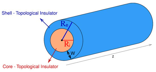
Figure 1.
Schematic representation of a concentric cylindrical structure composed of two topological insulators. The axial direction of the cylinder extends along the z-axis. The outer (shell) topological insulator is shown in blue, and the inner (core) topological insulator is shown in red. The external radius is indicated with a blue arrow, the internal radius with a red arrow, and the shell width with a black double arrow. The characteristic dimensions of and are on the order of tens of nanometers.
To implement the calculations required for the Rayleigh–Ritz method in the case of a single-material nanowire, we use the trial spinors given by
where N is the size of the chosen basis set; is the Bessel function with index L; is the n-th root of ; L is the quantum angular moment number; R is the radius of the cylinder; are the coefficients of the expansion (i.e., the linear variational parameters); and
is a normalization constant. Note that the spinor in Equation (8) satisfies the homogeneous boundary conditions, as .
We calculate the energy eigenvalues and eigenstates as functions of the longitudinal momentum using the Rayleigh–Ritz variational method. Figure 2 shows the energy spectra for cylinders of radius nm, computed with a basis size of and restricted to the angular momentum channel . The materials considered are (a) (blue, solid fill), (b) (red, striped) and (c) (green, dotted).

Figure 2.
Energy spectrum as a function of the z-component of the wavevector, , for cylindrical systems composed of a single topological insulator. The calculation was performed using a basis of functions. Only the energy for the angular momentum is shown. Each material is represented with a distinct color and fill pattern: (a) (blue, solid fill); (b) (red, striped); and (c) (green, dotted).
For all three materials, the energy gap appears to close at , consistent with the presence of gapless surface states. However, the curvature of the conduction and valence bands varies markedly between materials, reflecting differences in their effective masses and band dispersions. In all cases, two distinct surface states—one at high energy and one at low energy—are clearly distinguishable within a narrow momentum window around , approximately nm−1. This indicates that high-resolution momentum sampling is required to resolve surface features clearly. When considering more complex geometries, we will show that this accessible window becomes even narrower. These results will serve as a benchmark in Section 3.2, where we examine heterostructures formed by combining two different topological insulators.
Due to the finite radius of the cylinder, the gap at does not close completely, and a finite minigap persists between the surface states. For and , this minigap is approximately given by
where is the Fermi velocity in the azimuthal direction and R is the cylinder radius [19,52]. The Fermi velocity can be directly obtained from the parameters of the bulk Hamiltonian in Equation (2) through the relation [19]:
Using this expression, for a cylindrical nanowire of with external radius nm, the minigap takes the value meV.
Beyond the energy spectra, a crucial feature of topological insulators lies in the spin-momentum locking of their surface states. To characterize this property in cylindrical geometries, we compute the expectation values of the spin components in cylindrical coordinates. This provides insight into the orientation of spin currents and their relation to angular momentum and momentum along the z-axis. This information is especially relevant for identifying and characterizing topological surface states.
The spin components in cylindrical coordinates are given by:
where is the i-th component of the spinor .
We compute the expectation value for each spin component j, resolved by the angular momentum quantum number m. Figure 3 shows the expectation values of the spin components and as functions of the angular momentum L, evaluated for two representative longitudinal momenta: and nm−1.
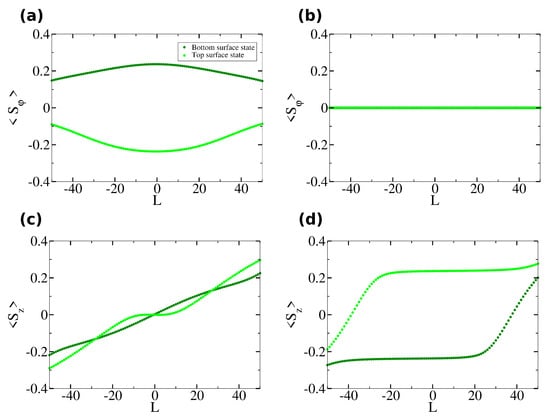
Figure 3.
Spin orientations as a function of angular momentum L for a solid cylinder made entirely of with radius . Panel (a) shows the expectation value of the azimuthal spin component at ; panel (b) shows at ; panel (c) shows the expectation value of the z-component at ; and panel (d) shows at . The lowest-energy surface state is shown in dark green, while the highest-energy surface state is shown in light green.
For , the axial spin component remains nearly constant at approximately in the low-angular-momentum regime (), forming a clear plateau that signals the presence of two topological surface states with opposite spin projections along the z-axis. At larger values, exhibits an approximately linear asymptotic behavior.
When nm−1, while a similar asymptotic trend is observed at large , the axial spin component becomes negligible near , suggesting that spin polarization along the cylinder axis is suppressed in this region.
The azimuthal spin component is identically zero for all L at whereas, for nm−1, it develops a peak (or dip) at that decays to zero as increases. The radial spin component vanishes identically for all L and is therefore not shown.
This spin current analysis confirms the topological nature of the low-energy states and provides a reference for identifying how these properties are modified in heterostructures or under external perturbations.
3.2. Wires with Core and Shell Made of Different Topological Insulator Materials
In this section, we consider a system composed of two topological insulators arranged in a cylindrical coaxial geometry, as illustrated in Figure 1. To model this kind of system, we use the hard-wall approximation; i.e., we assume that the parameters of the Hamiltonian in Equation (2), such as or , depend on the position. So, for a core–shell cylinder with a core made of and shell made of , we get that
To calculate the expectation values employed in the variational method, it is necessary to exercise some caution as the hard-wall approximation imposes a discontinuity on the parameters of the Hamiltonian. Since this discontinuity is in the radial coordinate, all terms in the Hamiltonian that depend on this coordinate should be analyzed. We present the mathematical details concerning the modifications introduced by a discontinuity in the Hamiltonian coefficients in Appendix B. Beyond these modifications, the numerical implementation proceeds along the lines described previously. The trial functions employed for the numerical calculations are the same as used in the previous subsection; see Equation (8).
The six panels of Figure 4 display the energy spectra corresponding to the six possible combinations of topological insulators forming the coaxial heterostructure. In all cases, a basis of functions was used, with an outer radius fixed at [nm], an inner radius set to , and calculations performed for the first ten angular momentum values: .
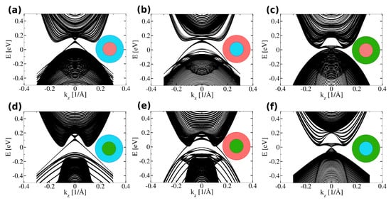
Figure 4.
Energy spectra as a function of the wavevector component along the cylinder axis, , for concentric cylindrical heterostructures composed of two topological insulators. In each panel we include eigenvalues calculated using the first ten angular momentum values . Each panel corresponds to a different core–shell material combination, with the core located at the center and the shell surrounding it. (a) core and shell; (b) core and shell; (c) core and shell; (d) core and shell; (e) core and shell; (f) core and shell. A transverse cross-section is shown in each case, with color coding used to distinguish the materials.
Figure 4 shows the conduction and valence band spectra of the core–shell systems comprising two topological insulators, which resemble superpositions of the energy spectra of the cylinders made from each constituent material individually. In contrast, the behavior of the in-gap topological states closely follows that of the outer material. This suggests the possibility of engineering nanowires in which the spectral features of the conduction and valence bands can be tuned via material composition, while the topological surface states can be selectively controlled through the choice of the outer topological insulator.
It is clear that combining materials whose conduction bands have different convexities considerably reduces the energy gap between the top of the valence band and the bottom of the conduction band, leaving less space to locate topological states. As a consequence, topological states exist in a reduced range of values; see, for instance, Figure 4a, where it is appreciable that there is a small cone “peeking out” from under the conduction band. The cone emerging from the conduction band is more noticeable. In this sense, the material of the shell dictates the characteristics of the cones containing the topological states; note the similarity to Figure 2a.
Another feature that it is necessary to analyze carefully is the bundles of eigenvalues that appear on the sides of the conduction or valence bands; see, for instance, Figure 4d,f. In the case of panel (d), the bundles appear at the sides of the valence band while, in the case of panel (f), they appear at the sides of the conduction band. For the case shown, the bundles are composed of exactly ten eigenvalues; that is, the number of different angular momenta used to obtain the spectra. So, in the limit , these bundles should form a single band. In the cases shown in panels (d) and (e), the valence and conduction bands would overlap, completely changing the behavior of the material. On the other hand, the patterns observed in the interior of the valence and conduction bands are the result of the presence of sub-bands with different symmetries.
Of course, the possibility of changing the ratio between the interior and exterior radii helps to select the spectra of interest. We focus now on the case shown in panel (f) of Figure 4, which seems adequate to display well-separated cones containing topological states. In particular, we explore what happens when the width of the shell changes.
In Figure 5, the inner radius is varied for a heterostructure composed of as the inner material and as the outer shell. As before, a basis of functions was used, and calculations were performed for the first ten values of the angular momentum L.
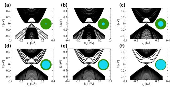
Figure 5.
Energy spectra as a function of the z-component of the wavevector, , for cylindrical core–shell structures composed of as the core and as the shell, with varying core radii. The spectra are shown for 10 different angular momentum values. Panels (a–f) correspond to increasing inner radii , given as a percentage of the outer radius : (a) ; (b) ; (c) ; (d) ; (e) ; (f) . The core–shell geometry for each configuration is illustrated with an inset image in each panel.
As the proportion of increases (i.e., as increases), the energy spectrum becomes increasingly populated in the region characteristic of , showing greater similarity with its bulk energy spectrum. This observation highlights the tunability of the spectral density through geometric design and material selection.
The group velocity of a particle is given by the expression:
Notably, for (see Figure 5d), topological states appear within the energy gap, while the conduction band exhibits a nearly flat dispersion with respect to . This implies that the group velocity of particles with energies near the conduction band minimum is significantly suppressed. Such flat-band behavior, which emerges from the appropriate combination of materials and geometry, is particularly appealing in contexts where reduced group velocity is advantageous—such as enhanced density of states or controlled localization.
To further clarify how the spectrum of a given heretostructure is built up when adding more and more eigenvalues corresponding to distinct values of the angular momentum, Figure 6 presents the eigenvalues calculated for (a) ; (b) and 4; (c) ; and (d) . It is easy to appreciate that the topological states correspond to those eigenvalues that accumulate near the highest and lowest eigenvalues (with ) for the valence and conduction band, respectively. It is also appreciable that the bundles of eigenvalues at the sides of the conduction band are not part of the topological states.
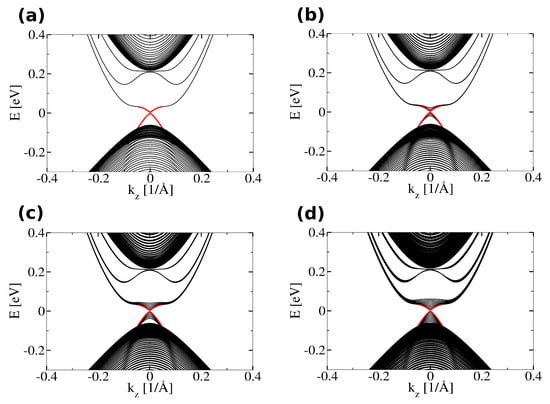
Figure 6.
Energy spectra obtained with increasing numbers of angular momentum states in a cylindrical core–shell structure composed of in the core and in the shell, with inner radius [nm] and outer radius [nm] (see Figure 5f). Panels (a–d) show the progressive inclusion of higher angular momentum components: (a) only; (b) to ; (c) to ; (d) to . The red curves correspond to the energy of the surface states with angular momentum number .
In Section 3.1, we used the expectation values of the spin operators and for different values of the angular momentum number L to provide evidence for the chiral character of the topological eigenstates, and to determine the relationship between angular momentum and the polarization in the z-direction; see Figure 3. In Figure 7, we plot the expectation values of the same spin operators as functions of the shell width, , for two different values of the wave vector . Interestingly, for small values of the width, nm, the expectation values are independent of the width, indicating that the properties of the topological states localized near the exterior border of the cylinder do not change too much unless the width is comparable to the localization length.

Figure 7.
Spin orientations as a function of shell width W for a concentric cylindrical heterostructure composed of in the core and in the shell, with outer radius and angular momentum . Panel (a) shows the expectation value of the z-component of the spin, , at ; panel (b) shows at ; and panel (c) shows the azimuthal component at . The lowest-energy edge state is shown in dark green and the highest-energy edge state is shown in light green.
Other quantities also contribute evidence that the topological states near the surface of the cylinder do not change considerably, despite the core–shell structure. In Figure 8, we plot the energy gap that separates the lowest and highest topological states on the conduction and valence bands, respectively. Along the solid black line—which corresponds to the gap between edge states of a cylinder with in the core and in the shell—letters show to which spectrum points on the plot correspond. Again, for a small range below nm, the energy gap is generally independent of W.
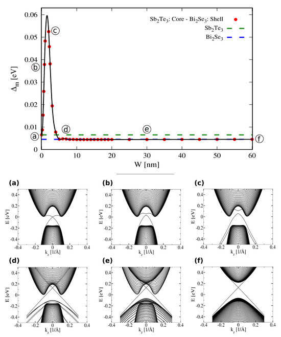
Figure 8.
Energy gap between edge states as a function of shell width W in a cylindrical core–shell structure with in the core and in the shell. Blue dots indicate the calculated gap values for each W, while the solid line corresponds to a polynomial fit. A truncated basis of functions was used, with fixed outer radius [nm], and . Panels (a–f) show selected configurations corresponding to representative values of W: (a) (fully ); (b) [nm]; (c) [nm]; (d) [nm]; (e) [nm]; (f) [nm] (fully ).
To further elucidate the role of the shell material in shaping the properties of the topological states, we analyzed the dependence of the minigap on the outer radius , while the core radius was set to . Figure 9 presents for different core–shell combinations, computed at and . As shown in the left panel, the curves cluster into three distinct sets, each corresponding to a specific shell material. Within each set, aligns closely with the value obtained for a homogeneous cylinder composed entirely of the respective shell material. This agreement indicates that the surface states, even in the presence of a different core, remain localized near the shell boundary and reflect its physical characteristics. To further contextualize these results, the right panel shows a rescaled version of the data, plotting , which corresponds to the effective azimuthal Fermi velocity via the relation
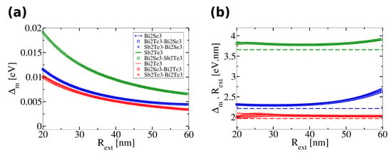
Figure 9.
(a) Energy gap as a function of the outer radius for cylindrical core–shell structures with different material combinations in the core and shell. Each of the three sets of curves is represented by a different color, corresponding to a specific pair of topological insulators. The gap is evaluated at , using a truncated basis of states and angular momentum . One material combination is omitted for clarity. (b) Scaled energy gaps as a function of . The dashed lines correspond to the analytical expression for the azimuthal Fermi velocity, (according to Ref. [19]), using the same color code as in panel (a) for each material combination. This comparison illustrates the asymptotic agreement between the numerically computed gaps and the effective surface-state velocity in the large-radius limit.
The variational method used here yields Fermi velocities that are systematically overestimated by up to for nm and for nm, compared to those obtained from effective Hamiltonian models. The curve corresponding to the – configuration is not shown as, for small , the surface states merge into the bulk bands and can no longer be resolved from the continuum.
4. Wires with an Empty Core
In this section, we consider a different kind of heterostructure than in the previous one. We aim to study the topological states that appear in a hollow wire, such as the one depicted in Figure 10. In other words, we aim to study the problem of a wire with homogeneous boundary conditions for the state vector at interior and exterior radii.
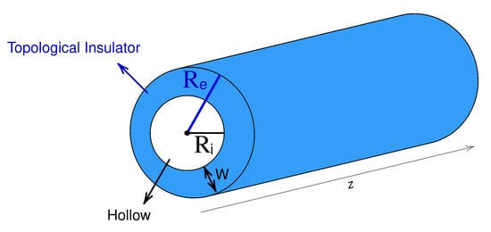
Figure 10.
Schematic representation of a concentric cylindrical structure composed of a topological insulator and an empty core. The axial direction of the cylinder extends along the z-axis. The topological insulator material is shown in blue. The external radius is indicated with a blue arrow, the internal radius with a black arrow, and the topological insulator width with a black double arrow. The characteristic dimensions of and are on the order of tens of nanometers.
To calculate the spectra of distinct cylinders, we employ the variational method again, although using a different basis set. The trial function now reads:
It is clear that the spinor in Equation (18) satisfies homogeneous boundary conditions when and , . The dependence on the quantum numbers L and is the same as that used to calculate approximate eigenvalues for nanowires made of a single or two materials. The trial function expectation values depend on integrals of sine functions, which have exact analytical expressions that are simpler to manage than those depending on Bessel functions. We provide some technical details in Appendix B.
Another interesting property of the trial function in Equation (18) is that it is not necessary to assume that there will be a topological state localized at each surface where there is a homogeneous boundary condition, as in Ref. [20]; and that, for small values of the width W, hybridization between the states localized at each surface will occur. Nevertheless, we aim to analyze the behaviors of several quantities to determine the physical changes produced when . Besides analyzing the localization, we study an adapted inverse participation ratio (IPR) [53,54,55,56], the expectation values of the spin operators and the fidelity between quantum states calculated for different widths.
When the width of the shell of the cylinder filled with material is large enough for each value of the quantum number L, there are two localized states—one on each surface. In this case, the localization length associated with each quantum state is smaller than the width of the material. Figure 11 shows the behavior of the energy of both topological states, each of which has a well-defined cone when plotted as a function of . In the following, we focus on hollow wires made of , as this material allows for a better appreciation of the phenomena associated with studying the limit .
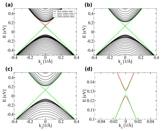
Figure 11.
Energy spectrum as a function of the z-component of the wavevector for different inner radii of a hollow cylinder made of . The outer radius is fixed at and the basis consists of functions. Panel (a) corresponds to an inner radius ; (b) to ; and (c) to . Panel (d) shows a zoom-in of the gap region in (c). Surface states located at the outer boundary are shown in green, inner surface states in red and bulk states in black.
Slightly changing the notation used in Equation (18) and writing the component of the k-th variational eigenfunction as
where
with and depending on or 4, we get that the probability density associated with the k-th eigenstate is expressed as
Figure 12 shows the probability densities for the border states for three different inner radii. In the leftmost column of panels, we plot the probability density for the state localized near the inner radius. In the rightmost column, we plot the probability density for the state localized near the exterior radius. The shell with a smaller width has nm. Although to the naked eye it seems that the probability density of both states in panels (e) and (f) do not overlap, we will see that, in order to assess the states localized at the borders of the shell, we need more nuanced quantities.
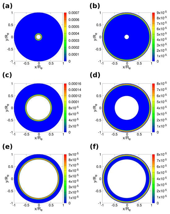
Figure 12.
Probability density for edge states in a hollow cylinder with outer radius . Both axes represent the normalized radial coordinate, . The calculations were performed using a truncated basis of functions, considering angular momentum and longitudinal wavevector . Panels (a,b) show the probability density for the inner and outer edge states, respectively, for a cylinder with inner radius ; panels (c,d) correspond to ; and panels (e,f) correspond to .
A hybridization regime for very thin films has been identified in Refs. [20,22,49,51,57]. In this regime, the helical states are not well-localized at the borders of the films. In the following, we study the behaviors of several quantities as functions of the shell width. For nanowires with an external radius nm and shell widths nm, the probability density function is appreciable over a region nm. In the hybrid regime, the probability density function is appreciable over the whole shell’s thickness; see Figure A1 in Appendix C.
In disordered systems—for instance, a finite disordered chain of spins—it is customary to define the inverse participation ratio [53,54,55,56]. Given a quantum state in the site basis, the inverse participation ratio of the state is calculated as
where the coefficients satisfy
and is the site basis set.
Of course, there is no obvious site basis set to use in a continuous problem. Therefore, instead of using a site basis, we study how some states spread over the function basis set.
To study the spatial localization of the eigenstates as a function of the inner radius of the cylinder and the width occupied by the material, we compute the inverse participation ratio (IPR) for each edge state k, defined as
where denotes the expansion coefficient of the k-th eigenstate in the variational basis, with labeling the spinor component and n labeling the radial mode index. The IPR serves as a measure of localization: larger values of indicate that the state is more spatially localized, while lower values correspond to more de-localized states.
Figure 13 shows the behaviors of two different quantities: the inverse participation ratio in Equation (24), and the coefficient of Ref. [20] (see Figure 3 of the reference). The solid points correspond to the values of , calculated for wires with different inner radius, as a function of the width occupied by the material. The color map corresponds to the coefficient . In Ref. [20], the authors derived an effective Hamiltonian for a hollow cylinder made of a topological insulator, starting from the Liu four-band Hamiltonian, Equation (2). In doing so, they introduced several width-dependent coefficients, including . It is appreciable that presents the same simple behavior for all the cases shown for those values of the width W where the coefficient changes appreciably.
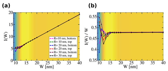
Figure 13.
Inverse Participation Ratio (IPR), denoted as , as a function of shell width W for a hollow cylinder at fixed longitudinal wavevector . Calculations were performed using basis functions and angular momentum . Results are shown for three different inner radii: , , and , as indicated in the legend. In panel (a), the background color map represents the variation of the parameter as defined in Ref. [20], allowing for a visual comparison between this quantity and the IPR. Panel (b) shows a rescaled version of the IPR as a function of W, in order to better highlight its variation relative to , emphasizing the correspondence between localization behavior and the features of the referenced parameter.
Although the changes shown by are not abrupt, this does not mean that physical quantities cannot exhibit noticeable changes. One of the advantages of using variational methods over an effective Hamiltonian is that we can calculate the expectation values of the spin operators and study the fidelity between quantum states.
Figure 14 shows the calculated expectation values of the spin operators and for cylinders whose shell width is in the range where the changes in the inverse participation ratio are appreciable. For , the changes in the expectation value of are barely noticeable; in contrast, for , the polarization in the z-direction grows noticeably at the expense of the helicity.

Figure 14.
Spin orientations as a function of shell width W for a hollow cylinder with outer radius and angular momentum . Panel (a) shows the expectation value of the z-component of the spin, , at ; panel (b) shows at ; and panel (c) shows the azimuthal component at . The lowest-energy inner edge state is shown in blue, the lowest-energy outer edge state in dark green, the highest-energy inner edge state in red and the highest-energy outer edge state in light green.
To further study the physical behaviors in the range , we employ the fidelity between pure quantum states. The fidelity and its derivatives, sometimes called fidelity susceptibility, allow for the detection of quantum phase transitions and crossovers [47,58,59,60].
In terms of quantum fidelities, a crossover can be identified as a smooth but rapid variation in the fidelity as the system transitions between different physical regimes. Given a control parameter , we define the quantum fidelity associated with the k-th eigenstate as
which quantifies the overlap between the same state computed at slightly different parameter values.
To enhance sensitivity to small deviations near , we introduce an auxiliary function defined as:
which diverges as , allowing for a sharper resolution of crossover behavior.
Figure 15b shows the behavior of computed for several values of . It can be observed that, for each choice of , the function differs only by a constant vertical shift. This suggests that can be decomposed as:
where is a function of the system parameter W (but constant in ), and is a constant with respect to W that depends only on the value of the fidelity increment .
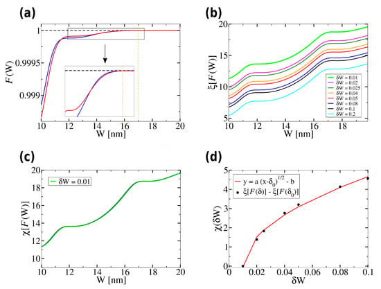
Figure 15.
Quantum fidelities as a function of shell width W for a hollow cylinder with fixed outer radius . Panel (a) shows the fidelity for a variation , where the lowest-energy inner surface state is shown in blue and the highest-energy inner surface state is shown in red. A zoom-in of the region near a fidelity transition (around the orange dashed line at ) is included. Panel (b) shows the auxiliary function for various values of , computed for the lowest-energy inner surface state. Panel (c) presents a data collapse of the curves, revealing a common scaling behavior. Panel (d) shows a quadratic-root fit of the scaling function for the highest-energy outer surface state. Black dots represent the numerical values of , and the red curve corresponds to a nonlinear fit of the form . The fitted parameters are and .
To obtain Figure 15c, the curve for was taken as a reference, and each of the remaining curves—corresponding to larger values of —were shifted by a constant offset. This procedure revealed that all curves collapse onto a single one.
To perform the alignment, the shift was computed as the difference between each curve and the reference curve at a fixed, arbitrarily chosen value of the parameter , according to the following equation:
This confirms that the dependence of on is purely additive, supporting the decomposition given in Equation (27).
The crossover behavior shown by the fidelity reveals the hybridization regime. Other quantities should also reveal this regime; in particular, the expectation values of the spin operator components. In Appendix D, we include Figure A2 showing the derivatives of two spin operator components
The derivatives of the expectation values also signal the presence of the hybridization regime, showing a markedly different behavior in the region , which is consistent with the range where the fidelity indicates a crossover behavior.
There are several quantum information quantities whose behavior separates topological from non-topological states, including the Kitaev–Preskill topological entropy [27], the entanglement spectrum [61] and the real-space quantum entropy [29]. Not all of these quantities are computable for every case, depending on symmetry factors, the availability of the many-particle quantum states and so on. In a previous paper, we used the fact that realistic border states in strong topological insulators have spinors with four components to calculate the Kitaev–Preskill entropy of border states in cylindrical nanowires composed of a single topological insulator. The topological entropy should be a constant for topological states, where the value of the constant depends on the topological properties.
To calculate the topological entropy , Kitaev and Preskill constructed a disk separated into three equal triangular sectors, where each one subtends an angle of . By labeling the sectors with the letters A, B and C and tracing out the spatial region outside a given sector, the topological entropy reads as
where S is the von Neumann entropy of the reduced quantum state given by
D is a spatial region taken from the set or , is the region of the space outside a sector D, and is the variational eigenstate that is an approximation for a topological or normal state; for more details, see Refs. [27,30].
Figure 16a shows the behavior of the topological entropy as a function of the wavevector for the inner and outer topological states, using the same color code as in Figure 14 and Figure 15a. Except for a dip at , it is clear that the topological entropy is for the outer states and for the inner states. The value of for the outer states is compatible with the result found in Ref. [30], while the value obtained for the inner states is not. We believe that this difference is due not to a difference in the topological properties of both sets of states but to the conditions required by the Kitaev–Preskill construction, which imposes that the spatial sectors and R must dwell outside the region where the topological state extends. For the outer states, it is a straightforward task to construct the triangular sectors fulfilling this condition. For the inner states, there is no way to do so—at least, if the triangular sectors have the same symmetry axis as the nanowire. Despite this fact, the topological entropy for the topological states is independent of , while for the non-topological states depends on ; see the corresponding black curves in Figure 16a.
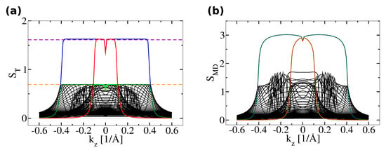
Figure 16.
Topological entropies as a function of the longitudinal wavevector component for a hollow cylinder with inner radius and outer radius . The calculation was performed using a truncated basis of functions, with angular momentum , and the entropy was evaluated within a disk of radius . The lowest-energy inner edge state is shown in blue, the lowest-energy outer edge state in dark green, the highest-energy inner edge state in red and the highest-energy outer edge state in light green. The dashed orange line indicates and the dashed violet line indicates . Panel (a) shows the Kitaev–Preskill quantum entropy, Equation (30). Panel (b) shows the mode-dependent quantum entropy, Equation (34).
The results shown in Figure 16b support the hypothesis that the inner and outer topological states share the same properties. In Ref. [30], we proposed a mode-dependent entropy, which distinguishes between topological and non-topological even better than the Kitaev–Preskill one as its value is far larger for topological states than for non-topological ones.
Following the notation of Ref. [30], we write the variational state as
and define the mode-dependent reduced density matrix , with matrix elements
where is a normalization constant such that , is the ring outside and is a matrix. The mode-dependent entropy is the von Neumann entropy of the mode-dependent reduced matrix,
Figure 16b shows the behavior of the mode-dependent entropy, , as a function of the wavevector . It is appreciable that the curves corresponding to the inner and outer states collapse into a single curve. The two colored curves now correspond to the upper and lower branches of the topological spectrum, which are distinguishable because they show abrupt decays at the values of where the energy of the topological states meets with the band of normal states; compare both panels of Figure 11 and Figure 16.
5. Discussion and Conclusions
In this work, we do not consider the inclusion of an external magnetic field for the sake of brevity. Nevertheless, the inclusion of a magnetic field will undoubtedly enrich the phenomenology observed in the band structure and the expectation values of spin operator components [19,38,48,49,62]. The addition of a uniform and time-independent magnetic field is straightforward through the Peierls substitution. Refs. [24,25,39,45] have discussed the procedure to include an magnetic field and its treatment using the Rayleigh–Ritz variational method. In the same sense, including electron–electron interactions is a different matter. The application of the Rayleigh–Ritz variational method to few-body problems is cumbersome, but doable; see, for instance, Refs. [63,64].
Our results reveal that the outer material in core–shell configurations predominantly governs the features of the low-energy edge states. In contrast, the bulk conduction and valence bands reflect a more intricate interplay between core and shell materials. The topological surface states retain their localization near the outer interface and display spin-momentum locking consistent with the underlying topology, even in the presence of radial discontinuities in material parameters.
Other core–shell structures can also be considered, such as a heterostructure composed of a topological insulator and a non–topological insulator. This would modify the boundary condition at the interface, as well as the specific values of the minigap and the expectation values of the spin operator components. The topological states are expected to remain robust against changes in boundary conditions: they would continue to localize near the interface, decaying strongly into the non–topological region. The situation in which the states and their expectation values are least affected likely appears when the core is made of a non–topological material and the shell is made of a topological one. It is expected that the topological states belonging to the Dirac cone will be only weakly affected; although additional surface states may emerge, as discussed in Ref. [57].
If the modulation of the spectral properties of a given TI is the purpose of constructing core–shell nanowires, our results draw a mixed scenario. It is clear that the effective azimuthal Fermi velocity, , is determined by the shell material. Of course, this is only a quantity related to what happens to the spectrum near . Nevertheless, wires with appropriate material combinations and inner and outer radii show remarkably flat portions on their spectra, as can be seen in Figure 6c. On the other hand, constructing core–shell nanowires using materials whose spectra have different concavities near could alter the global properties of the spectra, resulting in overlapping conduction and valence bands.
The presented numerical evidence indicates that energy gaps between topological states are weakly dependent on shell thickness beyond a threshold width, confirming the robustness of surface states against moderate geometric perturbations. Additionally, we showed that the inverse participation ratios, spin expectation values and quantum fidelity measures track and quantify the emergence and stability of edge-localized states in hollow TI cylinders. These tools allow for the identification of crossover regimes between hybridized and uncoupled surface modes as the shell width decreases. For uncoupled surface modes, we understand the usual picture employed to derive effective Hamiltonians; i.e., a surface state that decays exponentially away from the surface to which it is attached. For hybridized modes, we understand that the probability density at points near the middle of the shell width is comparable with that close to the borders of the shell, and is not negligible.
The understanding of the hybrid regime is still an open question from both theoretical and experimental points of view. Ref. [49] claimed that the hybrid regime would allow for measurement of the Quantum Spin Hall effect in scalable and controllable platforms. The authors found that the minigap energy presents an oscillating behavior as a function of the thickness of doped and thin films. In any case, interference and other phenomena appear when a magnetic field is applied and in the transport regime [48], both of which are beyond the scope of the present work. Although we did not explore the behavior of the minigap for hollow core wires, the comparison with the behavior observed on films would not be direct.
The variational approach implemented here proved to be flexible and accurate in capturing features of topological states under complex boundary and interface conditions. Unlike effective surface models, our method naturally incorporates bulk–boundary interplay, allowing for the direct computation of observables such as spin currents and entanglement measures. In particular, our results show that the spin current components depend on the shell width, opening the possibility of exploiting this dependence to tune the spin orientation of surface states. For example, in the region , one can selectively enhance either the azimuthal component or the axial component at a fixed momentum by adjusting the shell geometry.
The conversion between spin and charge currents in topological insulators has been identified as the key mechanism enabling their use in spintronic applications [65]. It is likely that favoring over modifies the spin–charge conversion process, due to changes in the probability density function of the edge states in the hybridized regime. Experimental evidence indicates that, in a thin film composed of a topological insulator, the torque per unit charge is larger than that associated with other studied mechanisms [62]. To analyze this possibility quantitatively, it is necessary to investigate the non–equilibrium regime and explicitly consider the interface between the topological insulator and a conductor, as discussed in Ref. [65].
The scaling behavior revealed by the fidelity is remarkable in its own way. Other quantities also indicate the hybridization regime responsible for the crossover behavior, as shown by the first derivatives of the expectation values of the spin operator components. At present, we lack the physical insight to formulate a quantitative relationship between the scaling behavior revealed by the fidelity and expectation values of physical quantities.
The topological states in hollow nanowires should have the same topological properties. Remarkably, the confirmation of this fact comes from results obtained for the mode-dependent entropy, which is independent of the basis set employed in the variational calculations; see Ref. [30]. Moreover, the mode-dependent entropy is more flexible to implement than the Kitaev–Preskill entropy in finite domains with topological states distributed on different regions of the domain.
Author Contributions
Conceptualization, N.L. and O.O.; methodology, N.L. and O.O.; software, N.L.; validation, N.L. and O.O.; formal analysis, N.L. and O.O.; investigation, N.L. and O.O.; resources, N.L. and O.O.; data curation, N.L. and O.O.; writing—original draft preparation, N.L. and O.O.; writing—review and editing, N.L. and O.O.; visualization, N.L. and O.O.; supervision, O.O.; project administration, O.O.; funding acquisition, O.O. All authors have read and agreed to the published version of the manuscript.
Funding
This research was funded by SECYT—Universidad Nacional de Córdoba, grant number 33620230100363CB; and CONICET, grant number 11220210100787CO.
Institutional Review Board Statement
Not applicable.
Informed Consent Statement
Not applicable.
Data Availability Statement
Available on request.
Acknowledgments
The authors acknowledge the fruitful and extended discussions with Federico Pont, Hernán Calvo and Karina Chattah (Universidad Nacional de Córdoba and CONICET), which provided important insights and contributed to the development of this work.
Conflicts of Interest
The authors declare no conflicts of interest.
Abbreviations
The following abbreviations are used in this manuscript:
| TIs | Topological Insulators |
| IPR | Inverse participation ratio |
Appendix A. The Rayleigh–Ritz Variational Method Eigenvalue Problem
The simpler Rayleigh–Ritz variational method requires a set of appropriate basis functions, which we denote as . The expectation value of the Hamiltonian
is obtained using a test function given by
and the minimization is performed over the values of the coefficients . This procedure results in an algebraic problem
where is an matrix whose entries are given by
is a vector that contains the c coefficients and the are the variational eigenvalues. N is the number of functions in the basis set, and the algebraic problem has N eigenvalues and their corresponding eigenvectors.
Appendix B. Coordinate Representation of the k · p Hamiltonian and Matching Conditions at the Interfaces Between Different Materials
In this Appendix, we discuss technical aspects regarding the implementation of the Rayleigh–Ritz variational method to the effective bulk Hamiltonian given in Equation (2). Particular care must be taken in the construction of variational bases that both preserve the spinorial nature of the wavefunctions and account for the boundary or interface conditions imposed by the nanowire geometry and material composition. Explicit forms of the trial functions employed for the concentric core–shell heterostructure and for the hollow cylindrical nanowire are given in Equations (8) and (18), respectively.
It is worth emphasizing that, given a four-component spinor wavefunction and N radial basis functions—see Equations (5), (8) and (18)—the projection of the Hamiltonian onto this basis leads to an algebraic problem with dimension , yielding eigenvalues together with their corresponding eigenvectors.
From a symmetry standpoint, the cylindrical nanowire retains translational invariance only along its axial direction (z axis); see Figure 1 and Figure 10. In contrast, in the transverse directions (x and y), the system is finite with characteristic lengths on the nanometer scale and, therefore, translational symmetry is lost. As a consequence, and must be represented as differential operators, while remains a good quantum number:
These definitions naturally lead to the operators and appearing in Equation (2), which are required to compute the Hamiltonian matrix elements once a variational basis is specified. For this purpose, it is convenient to rewrite the Cartesian derivatives in cylindrical coordinates, yielding
In the following subsections, we present the differential form of each operator in the Hamiltonian, as required for their application to the variational basis of the two systems under study, highlighting the specific technical aspects that arise in the core–shell heterostructure and in the hollow cylindrical nanowire.
Appendix B.1. Core–Shell Heterostructure
For a core–shell heterostructure composed of two distinct topological insulators, such as that illustrated in Figure 1, the basis functions must account for discontinuities in the material parameters at the radial interface. Therefore, each parameter in the Hamiltonian becomes a piecewise function of the radial coordinate , as the material composition changes at the core–shell interface:
where is an arbitrary parameter of the Hamiltonian, is the parameter corresponding to the core material, is the parameter associated with the shell material and is the Heaviside step function centered on .
When acting on functions that depend on the radial coordinate —such as the material parameters —the ordering of operators becomes important. To address this, we write
which ensures symmetric ordering of the momentum operators around the position-dependent coefficient [25]. This prescription is crucial in systems with spatially varying parameters, as it properly accounts for the radial derivatives acting on both the wavefunction and the coefficient functions.
Explicitly, the expression for becomes
where the second term of Equation (A14) introduces radial derivative couplings that effectively encode the matching conditions at the material interface.
Appendix B.2. Hollow Nanowire
In contrast to the core–shell heterostructure, no matching conditions are required in this case as the material is assumed to be homogeneous throughout the annular region. The differential operators acting on the wavefunctions must be expressed in cylindrical coordinates to properly act on the spinor components. The relevant momentum operators are given by
In this case, the kinetic terms in the Hamiltonian act only on the variational functions and not on spatially varying material parameters, simplifying the computation of the matrix elements in the variational procedure.
Appendix C. Probability Density Function for the Hybrid and Non-Hybrid Regimes
The probability density function allows for a better appreciation of the spatial extent of the helical states whose energy lies on the bulk gap. Figure A1 illustrates how the probability density of the topological states behaves within the shell region. As expected, the probability density vanishes at the cylinder boundaries and , consistent with the imposed homogeneous boundary conditions.
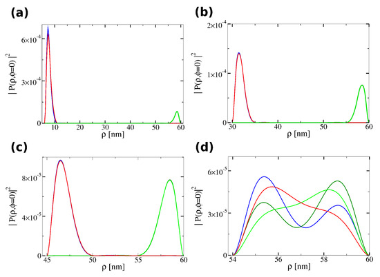
Figure A1.
Probability density of inner and outer edge states as a function of the radial coordinate for a hollow cylinder with outer radius . Due to the symmetry of the probability density along the azimuthal angle (see Figure 12), the plots are shown for . Panel (a) corresponds to an inner radius ; (b) to ; (c) to ; and (d) to . The color code used to distinguish the lowest- and highest-energy inner and outer edge states is the same as in previous figures. The calculations were performed with basis functions and angular momentum .
As discussed in the main text, outside the hybridization regime the helical states remain well localized near both the inner and outer interfaces, with the probability density appreciable only within a region of thickness . In contrast, within the hybridization regime, the probability density extends throughout the entire shell.
Appendix D. Derivatives for the Spin Component Expectation Values
In this Appendix, we present the first derivatives of the spin expectation values with respect to the shell width. Figure A2 shows the derivatives of the spin components for a hollow cylinder with outer radius . Although the absolute magnitude of the variation is small one can clearly see that, in the hybridization regime, the derivatives fluctuate and show an oscillatory behavior.

Figure A2.
Derivative of the spin orientation expectation values with respect to the shell width W for a hollow cylinder with outer radius . Panel (a) shows at ; panel (b) shows at ; and panel (c) shows at . The color code used to distinguish the different inner and outer edge states is the same as in previous figures. The calculations were performed with basis functions and angular momentum .
References
- Yu, R.; Qi, X.L.; Bernevig, A.; Fang, Z.; Dai, X. Equivalent expression of topological invariant for band insulators using the non-Abelian Berry connection. Phys. Rev. B 2011, 84, 075119. [Google Scholar] [CrossRef]
- de Lisle, J.; De, S.; Alba, E.; Bullivant, A.; Garcia-Ripoll, J.J.; Lahtinen, V.; Pachos, J.K. Detection of Chern numbers and entanglement in topological two-species systems through subsystem winding numbers. New J. Phys. 2014, 16, 083022. [Google Scholar] [CrossRef]
- Schnyder, A.P.; Ryu, S.; Furusaki, A.; Ludwig, A.W.W. Classification of topological insulators and superconductors in three spatial dimensions. Phys. Rev. B 2008, 78, 195125. [Google Scholar] [CrossRef]
- Klitzing, K.v.; Dorda, G.; Pepper, M. New Method for High-Accuracy Determination of the Fine-Structure Constant Based on Quantized Hall Resistance. Phys. Rev. Lett. 1980, 45, 494–497. [Google Scholar] [CrossRef]
- Laughlin, R.B. Anomalous Quantum Hall Effect: An Incompressible Quantum Fluid with Fractionally Charged Excitations. Phys. Rev. Lett. 1983, 50, 1395–1398. [Google Scholar] [CrossRef]
- Kane, C.L.; Mele, E.J. Quantum Spin Hall Effect in Graphene. Phys. Rev. Lett. 2005, 95, 226801. [Google Scholar] [CrossRef] [PubMed]
- Fidkowski, L. Entanglement Spectrum of Topological Insulators and Superconductors. Phys. Rev. Lett. 2010, 104, 130502. [Google Scholar] [CrossRef] [PubMed]
- Scharf, B.; Matos-Abiague, A.; Fabian, J. Magnetic properties of HgTe quantum wells. Phys. Rev. B 2012, 86, 075418. [Google Scholar] [CrossRef]
- Liu, J.; Hesjedal, T. Magnetic Topological Insulator Heterostructures: A Review. Adv. Mater. 2023, 35, 2102427. [Google Scholar] [CrossRef]
- Hasan, M.Z.; Kane, C.L. Colloquium: Topological insulators. Rev. Mod. Phys. 2010, 82, 3045–3067. [Google Scholar] [CrossRef]
- Liu, C.; Zhang, H.; Sun, Z.; Ding, K.; Mao, J.; Shao, Z.; Jie, J. Topological insulator Bi2Se3 nanowire/Si heterostructure photodetectors with ultrahigh responsivity and broadband response. J. Mater. Chem. C 2016, 4, 5648–5655. [Google Scholar] [CrossRef]
- Sharma, A.; Senguttuvan, T.D.; Ojha, V.N.; Husale, S. Novel synthesis of topological insulator based nanostructures (Bi2Te3) demonstrating high performance photodetection. Sci. Rep. 2019, 9, 3804. [Google Scholar] [CrossRef]
- Legg, H.F.; Loss, D.; Klinovaja, J. Metallization and proximity superconductivity in topological insulator nanowires. Phys. Rev. B 2022, 105, 155413. [Google Scholar] [CrossRef]
- Hu, J.; Luo, A.; Wang, Z.; Zou, J.; Wu, Q.; Xu, G. A numerical method for designing topological superconductivity induced by s-wave pairing. npj Comput. Mater. 2025, 11, 133. [Google Scholar] [CrossRef]
- Zhang, H.; Liu, C.X.; Qi, X.L.; Dai, X.; Fang, Z.; Zhang, S.C. Topological insulators in Bi2Se3, Bi2Te3 and Sb2Te3 with a single Dirac cone on the surface. Nat. Phys. 2009, 5, 438–442. [Google Scholar] [CrossRef]
- Liu, C.X.; Qi, X.L.; Zhang, H.; Dai, X.; Fang, Z.; Zhang, S.C. Model Hamiltonian for topological insulators. Phys. Rev. B—Condens. Matter Mater. Phys. 2010, 82, 045122. [Google Scholar] [CrossRef]
- Lu, H.Z.; Shan, W.Y.; Yao, W.; Niu, Q.; Shen, S.Q. Massive Dirac fermions and spin physics in an ultrathin film of topological insulator. Phys. Rev. B—Condens. Matter Mater. Phys. 2010, 81, 115407. [Google Scholar] [CrossRef]
- Nechaev, I.; Krasovskii, E. Relativistic k· p Hamiltonians for centrosymmetric topological insulators from ab initio wave functions. Phys. Rev. B 2016, 94, 201410. [Google Scholar] [CrossRef]
- Lou, W.K.; Cheng, F.; Li, J. The persistent charge and spin currents in topological insulator Bi2Se3 nanowires. J. Appl. Phys. 2011, 110, 093714. [Google Scholar] [CrossRef]
- Siu, Z.B.; Tan, S.G.; Jalil, M.B. Effective Hamiltonian for surface states of topological insulator nanotubes. Sci. Rep. 2017, 7, 45350. [Google Scholar] [CrossRef]
- Governale, M.; Bhandari, B.; Taddei, F.; Imura, K.I.; Zülicke, U. Finite-size effects in cylindrical topological insulators. New J. Phys. 2020, 22, 063042. [Google Scholar] [CrossRef]
- Martínez-Strasser, C.; Baba, Y.; Díaz-Fernández, Á.; Domínguez-Adame, F. Tailoring topological states of core–shell nanoparticles. Phys. E Low-Dimens. Syst. Nanostruct. 2022, 136, 115000. [Google Scholar] [CrossRef]
- Gao, D.; Ye, H.; Gao, L. Topology-tuned light scattering around Fano resonances by a core-shell cylinder. Opt. Express 2022, 30, 8399–8408. [Google Scholar] [CrossRef]
- Giovenale, N.; Osenda, O. Characterization of helical states in semiconductor quantum wells using quantum information quantities. Phys. E Low-Dimens. Syst. Nanostruct. 2022, 144, 115406. [Google Scholar] [CrossRef]
- Giovenale, N.; Osenda, O. Study of the transition from resonance to bound states in quantum dots embedded on a nanowire using the k · p method. Phys. B Condens. Matter 2022, 627, 413564. [Google Scholar] [CrossRef]
- Jia, G.Z.; Lou, W.K.; Cheng, F.; Wang, X.L.; Yao, J.H.; Dai, N.; Lin, H.Q.; Chang, K. Excellent photothermal conversion of core/shell CdSe/Bi2Se3 quantum dots. Nano Res. 2015, 8, 1443–1453. [Google Scholar] [CrossRef]
- Kitaev, A.; Preskill, J. Topological entanglement entropy. Phys. Rev. Lett. 2006, 96, 110404. [Google Scholar] [CrossRef]
- Giovenale, N.; Pont, F.M.; Serra, P.; Osenda, O. Convexity properties of superpositions of degenerate bipartite eigenstates. Phys. Rev. A 2019, 99, 052340. [Google Scholar] [CrossRef]
- Sterdyniak, A.; Chandran, A.; Regnault, N.; Bernevig, B.A.; Bonderson, P. Real-space entanglement spectrum of quantum Hall states. Phys. Rev. B—Condens. Matter Mater. Phys. 2012, 85, 125308. [Google Scholar] [CrossRef]
- Legnazzi, N.; Osenda, O. Quantum entropies of realistic states of a topological insulator. Phys. E Low-Dimens. Syst. Nanostruct. 2024, 159, 115922. [Google Scholar] [CrossRef]
- Avishai, Y.; Hatsugai, Y.; Kohmoto, M. Persistent currents and edge states in a magnetic field. Phys. Rev. B 1993, 47, 9501. [Google Scholar] [CrossRef]
- Richter, K.; Ullmo, D.; Jalabert, R.A. Orbital magnetism in the ballistic regime: Geometrical effects. Phys. Rep. 1996, 276, 1–83. [Google Scholar] [CrossRef]
- Prange, R. Three geometrical modifications of the surface-impedance experiment in low magnetic fields. Phys. Rev. 1968, 171, 737. [Google Scholar] [CrossRef]
- Heuser, M.; Hajdu, J. On diamagnetism and non-dissipative transport. Z. Phys. 1974, 270, 289–293. [Google Scholar] [CrossRef]
- Yerin, Y.; Gusynin, V.; Sharapov, S.; Varlamov, A. Genesis and fading away of persistent currents in a Corbino disk geometry. Phys. Rev. B 2021, 104, 075415. [Google Scholar] [CrossRef]
- Maisel Licerán, L.; Koerhuis, S.; Vanmaekelbergh, D.; Stoof, H. Topology of Bi2Se3 nanosheets. Phys. Rev. B 2024, 109, 195407. [Google Scholar] [CrossRef]
- Shan, W.Y.; Lu, H.Z.; Shen, S.Q. Effective continuous model for surface states and thin films of three-dimensional topological insulators. New J. Phys. 2010, 12, 043048. [Google Scholar] [CrossRef]
- Qi, X.L.; Zhang, S.C. Topological insulators and superconductors. Rev. Mod. Phys. 2011, 83, 1057–1110. [Google Scholar] [CrossRef]
- Ravi Kishore, V.V.; Partoens, B.; Peeters, F.M. Electronic and optical properties of core–shell nanowires in a magnetic field. J. Phys. Condens. Matter 2014, 26, 095501. [Google Scholar] [CrossRef]
- Bogolubov, N., Jr.; Soldatov, A.; Kruchinin, S. The theory of quantum dots in external magnetic field. Quantum Matter 2015, 4, 352–357. [Google Scholar] [CrossRef]
- Garagiola, M.; Osenda, O. Excitonic states in spherical layered quantum dots. Phys. E Low-Dimens. Syst. Nanostruct. 2020, 116, 113755. [Google Scholar] [CrossRef]
- Fernández, F.M. On the Rayleigh-Ritz variational method. arXiv 2022, arXiv:2206.05122. [Google Scholar]
- Blanchard, P.; Brüning, E. The Variational Approach to Linear Boundary and Eigenvalue Problems. In Variational Methods in Mathematical Physics: A Unified Approach; Springer: Berlin/Heidelberg, Germany, 1992; pp. 142–170. [Google Scholar] [CrossRef]
- Nesbet, R.K. Variational Principles and Methods in Theoretical Physics and Chemistry; Cambridge University Press: Cambridge, UK, 2002. [Google Scholar]
- Krishtopenko, S.S.; Knap, W.; Teppe, F. Phase transitions in two tunnel-coupled HgTe quantum wells: Bilayer graphene analogy and beyond. Sci. Rep. 2016, 6, 30755. [Google Scholar] [CrossRef]
- Krishtopenko, S.S.; Teppe, F. Realistic picture of helical edge states in HgTe quantum wells. Phys. Rev. B 2018, 97, 165408. [Google Scholar] [CrossRef]
- Garagiola, M.; Cuestas, E.; Pont, F.M.; Serra, P.; Osenda, O. Detecting dimensional crossover and finite Hilbert space through entanglement entropies. Phys. Rev. A 2016, 94, 042115. [Google Scholar] [CrossRef]
- Behner, G.; Jalil, A.R.; Heffels, D.; Kölzer, J.; Moors, K.; Mertens, J.; Zimmermann, E.; Mussler, G.; Schüffelgen, P.; Lüth, H.; et al. Aharonov-Bohm interference and phase-coherent surface-state transport in topological insulator rings. Nano Lett. 2023, 23, 6347–6353. [Google Scholar] [CrossRef]
- van Veen, F.; Kölling, S.; de Wit, S.R.; Metsch, R.; Rosenbach, D.; Li, C.; Brinkman, A. Observation of the surface hybridization gap in the electrical transport properties of the ultrathin topological insulator (Bi1−xSbx)2Te3. Phys. Rev. B 2025, 112, 045425. [Google Scholar] [CrossRef]
- Dziawa, P.; Kowalski, B.; Dybko, K.; Buczko, R.; Szczerbakow, A.; Szot, M.; Łusakowska, E.; Balasubramanian, T.; Wojek, B.M.; Berntsen, M.; et al. Topological crystalline insulator states in Pb1−xSnxSe. Nat. Mater. 2012, 11, 1023–1027. [Google Scholar] [CrossRef] [PubMed]
- Gioia, L.; Christie, M.; Zülicke, U.; Governale, M.; Sneyd, A. Spherical topological insulator nanoparticles: Quantum size effects and optical transitions. Phys. Rev. B 2019, 100, 205417. [Google Scholar] [CrossRef]
- Zhang, Y.; Ran, Y.; Vishwanath, A. Topological insulators in three dimensions from spontaneous symmetry breaking. Phys. Rev. B—Condens. Matter Mater. Phys. 2009, 79, 245331. [Google Scholar] [CrossRef]
- Viola, L.; Brown, W.G. Generalized entanglement as a framework for complex quantum systems: Purity versus delocalization measures. J. Phys. A Math. Theor. 2007, 40, 8109. [Google Scholar] [CrossRef]
- Giraud, O.; Martin, J.; Georgeot, B. Entanglement of localized states. Phys. Rev. A 2007, 76, 042333. [Google Scholar] [CrossRef][Green Version]
- Haake, F. Quantum Signatures of Chaos. In Quantum Coherence in Mesoscopic Systems; Springer: Boston, MA, USA, 1991; pp. 583–595. [Google Scholar] [CrossRef]
- Zwick, A.; Osenda, O. Quantum state transfer in a XX chain with impurities. J. Phys. A Math. Theor. 2011, 44, 105302. [Google Scholar] [CrossRef]
- Tchoumakov, S.; Jouffrey, V.; Inhofer, A.; Bocquillon, E.; Plaçais, B.; Carpentier, D.; Goerbig, M. Volkov-Pankratov states in topological heterojunctions. Phys. Rev. B 2017, 96, 201302. [Google Scholar] [CrossRef]
- You, W.L.; Li, Y.W.; Gu, S.J. Fidelity, dynamic structure factor, and susceptibility in critical phenomena. Phys. Rev. E 2007, 76, 022101. [Google Scholar] [CrossRef]
- Huang, L.; Wang, Y.; Wang, L.; Werner, P. Detecting phase transitions and crossovers in Hubbard models using the fidelity susceptibility. Phys. Rev. B 2016, 94, 235110. [Google Scholar] [CrossRef]
- Falcão, P.R.N.; Aramthottil, A.S.; Sierant, P.; Zakrzewski, J. Many-body localization crossover is sharper in a quasiperiodic potential. Phys. Rev. B 2024, 110, 184209. [Google Scholar] [CrossRef]
- Li, H.; Haldane, F.D.M. Entanglement Spectrum as a Generalization of Entanglement Entropy: Identification of Topological Order in Non-Abelian Fractional Quantum Hall Effect States. Phys. Rev. Lett. 2008, 101, 010504. [Google Scholar] [CrossRef]
- Mellnik, A.R.; Lee, J.; Richardella, A.; Grab, J.L.; Mintun, P.J.; Fischer, M.H.; Vaezi, A.; Manchon, A.; Kim, E.A.; Samarth, N.; et al. Spin-transfer torque generated by a topological insulator. Nature 2014, 511, 449–451. [Google Scholar] [CrossRef]
- Osenda, O.; Serra, P. Scaling of the von Neumann entropy in a two-electron system near the ionization threshold. Phys. Rev. A—At. Mol. Opt. Phys. 2007, 75, 042331. [Google Scholar] [CrossRef]
- Serra, P.; Neirotti, J.P.; Kais, S. Electronic structure critical parameters for the lithium isoelectronic series. Phys. Rev. Lett. 1998, 80, 5293. [Google Scholar] [CrossRef]
- Zhang, S.; Fert, A. Conversion between spin and charge currents with topological insulators. Phys. Rev. B 2016, 94, 184423. [Google Scholar] [CrossRef]
Disclaimer/Publisher’s Note: The statements, opinions and data contained in all publications are solely those of the individual author(s) and contributor(s) and not of MDPI and/or the editor(s). MDPI and/or the editor(s) disclaim responsibility for any injury to people or property resulting from any ideas, methods, instructions or products referred to in the content. |
© 2025 by the authors. Licensee MDPI, Basel, Switzerland. This article is an open access article distributed under the terms and conditions of the Creative Commons Attribution (CC BY) license (https://creativecommons.org/licenses/by/4.0/).