Abstract
Froth flotation is a widely used method for the selective separation of particulates from aqueous dispersions or slurries. This technology is based on the attachment of sufficiently hydrophobic particles to the air–water interface of gas bubbles. However, when the target particles are strongly hydrophilic, the requirement of hydrophobicity limits the effectiveness of conventional froth flotation. A prominent example is the deinking step in paper recycling, where modern hydrophilic inkjet inks are difficult to remove by flotation. In this study, we evaluated oil-coated bubble flotation as an alternative to conventional air flotation for removing inkjet ink from pulped newsprint. We examined the effects of oil type, salt type and concentration, and pH on deinking efficiency. Compared with traditional air flotation, oil-coated bubble flotation produced substantial improvements in standard performance metrics, including ISO brightness, effective residual ink concentration (ERIC), and the fiber retention of recycled paper pads.
1. Introduction
Froth flotation is a highly efficient process used to separate hydrophobic particles from aqueous suspensions [1]. For more than a century, it has been applied in many different areas, including mining operations [2,3], wastewater treatment [4,5], oil recovery [6,7], and paper recycling [8,9], to name but a few. The basic mechanism is that a gas bubble rising through an aqueous medium can collect sufficiently hydrophobic particles due to particle affinity for the bubble’s air–water interface. The rising particle-laden bubbles eventually reach the top surface of the suspension and create a layer of froth that can be skimmed off easily. Effective particle removal requires that the collected particles remain firmly attached to the air–water interface of the rising bubbles and the froth. An adsorbed particle’s attachment strength is sensitive to its penetration into the interface upon adsorption [10]. Hydrophilic particles, which expose very little of their surface to the gas side of the interface, can attach only weakly. As a result, they may require only small levels of agitation to escape the interface and re-disperse in the liquid bulk. Given the hydrophilic nature of many water-dispersible particles, conventional froth flotation for aqueous suspensions is typically selective for the most hydrophobic particles in the suspension. Indeed, in coal-ore and metal-ore flotation, undesired hydrophobic particles are treated with depressants (e.g., by chemical modification [11] or adsorption with polysaccharides [12]) to make them more hydrophilic and promote their retention in the aqueous phase.
In the paper recycling industry, froth flotation is used in deinking [8,9]. Gas bubbles are injected into the pulp suspension, where they lift dispersed ink particles to the top surface. Traditional offset printing uses hydrophobic ink particles that adsorb strongly at an air–water interface and are therefore easily removed from aqueous dispersions by froth flotation. A trend in high-volume print applications has been to replace offset printing with inkjet printing, which is considered more environmentally benign [13]. However, the small hydrophilic pigments in aqueous inkjet inks do not have the same affinity for air bubbles as traditional hydrophobic inks. As a result, they cannot be removed as effectively by air flotation as hydrophobic inks, which limits their recyclability [14]. A straightforward approach to this problem is to render the particles more hydrophobic. Reagents called collectors can selectively adsorb onto the particle surface and tune their hydrophobicity [15,16]. As early as the 1920s, various oils (such as coal tar derivatives, crude petroleum, wood tar, and pine oil) were used as collectors for sulfide mineral flotation [1]. Many other substances including fatty acids and surfactants have also been used, but interactions among collectors and other additives such as dispersants, activators, or depressants can have undesired side effects [1,17].
An alternative strategy uses oils to tune the surface properties of gas bubbles instead of particles. By coating the bubbles with a thin film of oil, the bubble surface can be adjusted to be less hydrophobic (compared to an uncoated bubble). The oil-coated bubbles can thus promote the adsorption of more hydrophilic particles at the oil–water interface. The oily bubble coat can also be used as a vehicle for small amounts of oil-soluble amphiphiles that further optimize particle wetting at the oil–water interface [17,18]. This strategy, known as “reactive oily bubble flotation”, has been explored for the selective recovery of minerals and low-rank (hydrophilic) coals [19,20]. Oil-coated bubbles have also been applied to the separation of bitumen [21,22]. Chen et al. [15] and Tarkan et al. [23,24] developed a process known as compressed air-assisted solvent extraction, which uses micron-sized solvent-coated air bubbles for bitumen recovery and metal extraction. In the context of deinking, Pelton and coworkers reported the use of a silicone oil aerosol in flotation deinking. They concluded that the presence of a thin oil coat surrounding the bubbles can enhance deinking performance [25,26]. However, the mechanism underlying the improvement and influence of individual system parameters has not been fully investigated. Furthermore, the use of oil-coated bubbles to remove the more hydrophilic particles found in inkjet inks has not been reported.
In our prior work, we investigated the rise dynamics of oil-coated bubbles through aqueous media, which is closely related to flotation performance [27]. We demonstrated that oil-coated bubbles display a more spherical and stable shape and straighter trajectory yet rise slower than uncoated bubbles of comparable size. This indicates two hydrodynamic benefits of oil-coated bubble flotation. On one hand, oil-coated bubbles have a longer residence time in the slurry and thus more time to interact with and collect the targeted particulates. On the other hand, the collected cargo is better protected against detachment from the rising bubbles, whose hydrodynamic perturbations are reduced by the oil coat.
Conversely, the presence of an oily bubble coat may decrease the induction time required for the rupture of the aqueous film initially separating particles from a contacting bubble. This is a kinetic effect related to the fact that the London dispersion force between a particle and an oily bubble coat is attractive, whereas the corresponding force between a particle and a bare bubble is repulsive [28]. This kinetic advantage of oil-coated bubbles combines synergistically with the hydrodynamic advantage mentioned above, with the thermodynamic benefit of more favorable wetting and thus stronger particle attachment. The confluence of these effects explains why oil-coated bubbles can outperform uncoated bubbles in the flotation separation of hydrophilic particles.
The objective of this study is to evaluate the application of oil-coated bubbles to remove hydrophilic ink and to better understand the effects of system parameters on recovery efficiency. We have investigated the impact of oil type, salt type, salt concentration, and pH using a miniaturized deinking test on a model of water-dispersed ink. We have also carried out deinking performance tests on a lab-scale flotation deinking column by analyzing paper pads from recycled newsprint. Oil-coated bubble deinking was compared to uncoated bubble deinking by measuring the ISO brightness and the effective residual ink concentration (ERIC) of the paper pads. According to both metrics, the oil-coated bubbles exhibit significant benefits in the removal of hydrophilic inks compared with traditional uncoated bubbles. At the same time, the introduction of a bubble coat is seen to improve the retention of cellulose fibers during deinking.
2. Results and Discussion
2.1. Miniaturized Deinking Evaluation
There are several important system parameters involved in oil-coated bubble deinking, such as oil type, salt type, salt concentration, and pH. To evaluate the impact of each individual parameter efficiently, we designed a miniaturized deinking test performed by mechanically frothing a mixture of particles, water, and oil in a small vial (Figure 1). Our recent studies suggest that air bubbles are introduced into the bulk aqueous phase during homogenization [28,29,30]. The small amount of oil supplied can spread at the air–water interface of the bubbles to form a thin oil coating. These oil-coated bubbles can either be partially coated or completely coated, depending on the spreading coefficient of the oil [28,29,30]. The miniaturized deinking test serves as a convenient and efficient method to screen various parameters for the creation of air–water or oil–water interfaces that allow for particle adsorption. We acknowledge that in addition to oil-coated bubbles, frothing in a small vial can also produce oil droplets. We do not know what fraction of the oil is present in the form of droplets versus oily bubble coats. Either form presents the particles with an oil–water interface for attachment and removal. For the purpose of a quick screening, we accept the uncertainty regarding the oil distribution, which is more thoroughly investigated in follow-up experiments.
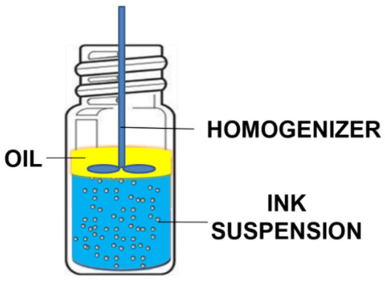
Figure 1.
Simplified diagram of the miniaturized deinking test.
The effect of oil type on the ink particle removal efficiency is shown in Figure 2. In the presence of a small amount of oil, the ink separation efficiency is significantly enhanced. It is interesting that there is a noticeable difference in using different types of oils, arguably resulting from the variance of interactions between the oil and the hydrophilic ink particles. Such interactions are expected to depend on oil polarity. We observed that 1-octanol, the most polar of the tested oils (as indicated by the literature value of relative permittivity (εr) shown in Table 1), gave the highest ink removal efficiency of 96.1% ± 1.9%. The other four types of oil share similarly low permittivity (polarity) values, but they still displayed lower ink particle removal efficiencies than 1-octanol. These effects can be understood in terms of polarity’s influence on the London dispersion interaction, which is usually the dominant contribution to the van der Waals (VDW) force. These interactions are repulsive for two dissimilar bodies interacting across a medium if (and only if) that medium has a refractive index (n = εr1/2) intermediate between that of the two bodies [31]. Water (our medium) has a lower refractive index than just about any oil and any particle but a higher one than air; thus, a water-dispersed particle is attracted to oil but repelled from air. The connection with the polarity is that the refractive index and hence the dielectric constant is determined by the polarizability at optical and UV frequencies. For the qualitative effect of oil polarity (attraction vs. repulsion), all that matters is that the oils have a higher refractive index than water, whereas air does not. The attractive potential confers a thermodynamic advantage upon adsorption for nearly all oils. However, oils with higher polarity bind particles more strongly in their oil–water interface because of a more favorable oil–particle–water contact angle that results from the VDW forces. Additionally, the absence of a VDW contribution to the particle–oil potential confers a kinetic advantage during particle adsorption as well. This is because the repulsive VDW contribution to the particle–air potential adds to the energy barrier that must be overcome for adsorption to occur during a collision.
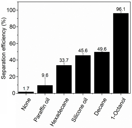
Figure 2.
Simplified diagram of the miniaturized deinking test. NaCl concentration is 50 mM and pH is 7.
However, these trends in separation efficiency varied over a wider range than expected based solely on their similarly low dielectric constants from 2.0 to 2.8. We posit that the different viscosities of the three alkanes (Table 1), may play a role in determining separation efficiency by controlling the rate at which oil spreading on bubbles occurs. Paraffin oil has a viscosity >100× that of decane, hexadecane’s viscosity is ~10× more than decane, and these oils show a separation efficiency that is inversely proportional to viscosity. Through its influence on the oil spreading rate, higher viscosity is expected to limit the rate of formation of oil-coated bubbles in the screening experiments, thereby limiting the available oil-coated bubble surface area for particle attachment. Viscosity is known to play a dominant role in controlling the rate of surface tension-driven spreading of oil at air–water interfaces [32]. We expect that both LaPlace (surface tension) and Marangoni (surface tension gradient) forces drive spreading in our system. This is because inks often contain amphiphilic components that will adsorb at the water–air or water–oil interface and lead to Marangoni forces in addition to LaPlace forces. In LaPlace spreading, the rate is proportional to μ−1, where μ = dynamic viscosity. In Marangoni spreading, the rate is ~μ1/3. On the other hand, silicone oil and octanol, despite having viscosities of the same magnitude as hexadecane, have better separation performance. This indicates that the viscosity effect may be tempered by their higher dielectric constants, which promotes stronger ink particle adsorption to the oil-coated bubbles, as discussed above.

Table 1.
Relative permittivity (dielectric constant) and viscosity at 25 °C of oils used in the miniaturized deinking test.
Table 1.
Relative permittivity (dielectric constant) and viscosity at 25 °C of oils used in the miniaturized deinking test.
| Oil | Paraffin Oil | Hexadecane | Silicone Oil | Decane | 1-Octanol |
|---|---|---|---|---|---|
| Relative permittivity | 2.2 [33] | 2.0 [34] | 2.2–2.8 [33] | 2.0 [35] | 10.3 [35] |
| Viscosity mPa s | 120 a | 3.0 [36] | 10 a | 0.9 [13] | 7.7 [37] |
a Reported by manufacturer.
2.1.1. Effect of Salt Concentration and Type
As is well understood in flotation, we expect that both the ink particles and bubble surfaces will carry an electrostatic charge that will give rise to some level of particle–bubble repulsion [1]. This repulsion can present a barrier to particle attachment, which can be screened by adding salt. Furthermore, we expect added salt to also aid the separation through salt-induced particle aggregation. In systems with sheared fluid, e.g., due to stirring or rising bubbles, the collision rate increases strongly as a function of the particle size. The rate of shear-induced “orthokinetic” collisions (as distinguished from perikinetic collisions due to Brownian motion) scales with the cube of the particle size [38,39].
The impact of salt concentration on ink particle zeta potential is shown in Figure 3 (note: numerical data for this and other plots is provided in the Supplementary Materials). As expected, the salts decrease the magnitude of the zeta potential (they become less negative), indicative of charge screening. The effect is strongest for the divalent salts, which yield a higher ionic strength for a given salt concentration than the monovalent salts, which all show a similar, weaker screening effect. This feature was also observed in a study of conventional froth flotation of graphite [40]. Figure 4 shows the effect of NaCl concentration on ink particle removal efficiency with and without decane. Decane is used as the oil here because it exhibited intermediate ink removal performance compared with other oils (as shown in Figure 2) and may better reveal the influence of salt on deinking. In the absence of decane, although removal efficiency is low, increasing salt concentration does afford small improvements in efficiency, arguably by screening the electrostatic repulsion experienced by ink particles. However, even screened hydrophilic ink particles do not have strong affinity for the air–water interface and will largely remain in the aqueous phase. In the presence of decane, as discussed in the introduction, the ink particles have better thermodynamic affinity and a reduced kinetic adsorption barrier compared to an air–water interface. The presence of salt clearly further improves the separation efficiency, through it increases charge screening and lowers the electrostatic repulsive adsorption barriers.
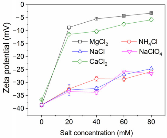
Figure 3.
Ink particle zeta potential versus salt concentration at neutral pH.
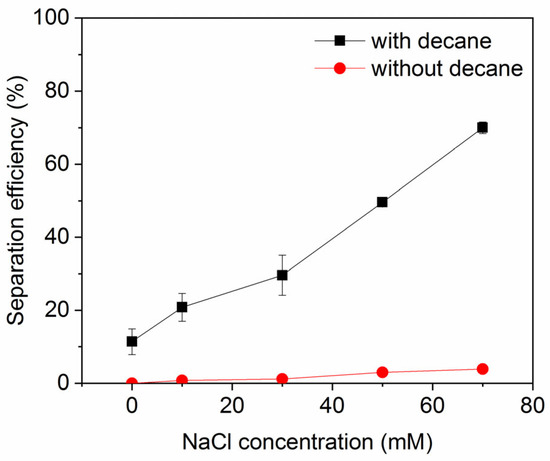
Figure 4.
Ink particle separation efficiency as a function of NaCl concentration at neutral pH. Error bars smaller than the symbol size are not visible.
The impact of salt type on the ink particle removal efficiency at constant ionic strength in the presence and absence of decane is shown in Figure 5. Even at the same ionic strength, there is significant variation between different salts. In all cases, the decane produces a dramatic enhancement in the removal efficiency. The divalent salts alone already boost the removal efficiency to over 60%, most likely because the divalent cations, in addition to screening the electrostatic repulsion between the particles and bubbles, can also adsorb specifically to hydrophobic bubble surfaces [41,42]. The additional presence of decane further raises ink removal efficiency to 94% in the divalent salt solutions. In the monovalent electrolyte, removal efficiencies are generally lower, as one might expect, but we still see a significant boost in the presence of decane. We also observe a rather striking variation between the different monovalent electrolytes, with removal efficiency in the order of NaClO4 (lowest efficiency), NaCl, and NH4Cl (higher efficiency). This strong variation is challenging to rationalize, but we point to a qualitative correlation with the ordering of ions in the well-known Hofmeister series. Perchlorate is a more chaotropic anion than chloride and would be expected to have a stronger tendency to adsorb at a hydrophobic bubble surface than chloride [43]. Perchlorate would thus increase the negative bubble charge and the particle–bubble repulsion to the detriment of the particle removal efficiency. Conversely, the ammonium ion is more chaotropic than the sodium ion and more likely to adsorb to a negatively charged hydrophobic surface [44] and thus reduce the bubble charge and particle–bubble repulsion to the benefit of removal efficiency.
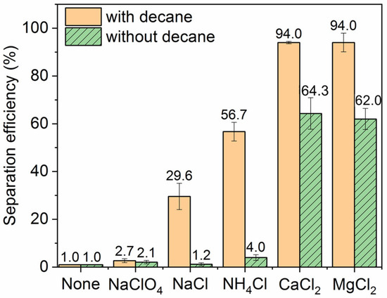
Figure 5.
Effect of salt type on the ink particle removal efficiency. Ionic strength is 30 mM when salt is added and pH is neutral. For the “None” control with no salt or oil added, the separation efficiency is merely 1.0%.
Figure 6 shows the change in particle size over time in the presence of different salts. It is worth noting that dynamic light scattering (DLS) determination is known to be less accurate for particles larger than 1 μm, but it still offers valuable insights that CaCl2 and MgCl2 enhance the aggregation and agglomeration of the ink particles more than the monovalent salts, therefore promoting the removal of ink particles by rising gas bubbles. These observations are consistent with the well-known Schulze–Hardy rule: multivalent counter ions destabilize colloidal suspensions much more effectively than monovalent counter ions [45,46]. The significance of particle aggregation is that the ensuing increase in particle size strongly increases the rate of (orthokinetic) particle collisions with the bubbles, as mentioned before.
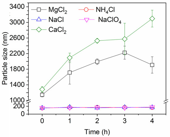
Figure 6.
Ink particle size over time in the presence of different salts. Ionic strength is 30 mM and pH is neutral.
2.1.2. Effect of pH
Figure 7 shows the impact of pH on the ink particle removal efficiency both in the absence and presence of decane. A lower pH enhances the removal of ink particles from water, regardless of the presence of oil. This is consistent with the particle zeta potential and particle size results shown in Figure 8 and Figure 9. Less surface charge at a lower pH means a lower energy barrier to particle adsorption; therefore, ink particles adsorb more readily at the air–water or oil–water interface associated with bubbles. The hydrophilic ink used has an isoelectric point around pH 3. With increasing negative charge developed above this pH (Figure 8), the repulsive particle adsorption barrier near the oil–water or air–water interface is increased. If particles can aggregate, as noted above, the hydrodynamics of larger particles enhance their ability to overcome the adsorption barrier. However, as the pH increases beyond 4, the ink particles are unable to form these beneficial large aggregates and the ink removal efficiency is lower.
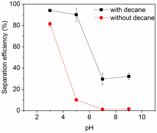
Figure 7.
Ink particle separation efficiency as a function of pH in the presence of 30 mM NaCl. Error bars smaller than the symbol size are not visible.
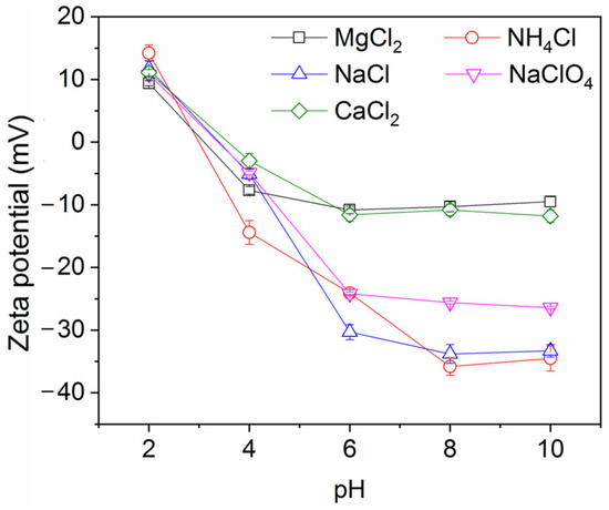
Figure 8.
Ink particle zeta potential versus pH. Ionic strength is 30 mM.
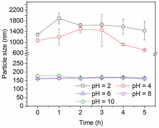
Figure 9.
Ink particle size over time at different pH values in the presence of 30 mM NaCl.
2.2. Lab-Scale Deinking Test
Based on the above results from the miniaturized deinking tests, conducted to evaluate the impact of individual system parameters, we performed deinking tests on ink–water mixtures, similar to those above, by using a lab-scale frothing apparatus. Figure 10 shows a qualitative visual comparison between conventional flotation deinking and decane-assisted flotation deinking. When the gas flow containing decane mist was fed, the deinking performance was significantly improved compared to the gas flow not containing oil. This is indicated by visual clarification of the aqueous suspension in Figure 10, which is consistent with the previous results from the miniaturized deinking tests.
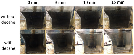
Figure 10.
Comparison of lab-scale deinking using conventional flotation and decane-assisted flotation. Images show side view of flotation chamber as a function of time after gas flow is started, with and without decane. There is 10 mM MgCl2 in both cases and pH is neutral.
Next, we extended the frothing experiments to demonstrate deinking from newsprint bearing print patterns that used the same ink as above. We followed a standard INGEDE protocol to print test patterns with the hydrophilic ink onto recycled newsprint, which was then pulped and deinked with the lab flotation apparatus. As a reference, the pulping step (without frothing) improved the ISO brightness of the pads from 54.3% ± 3.0% to 57.5% ± 0.8% (tested using unprinted papers).
Figure 11 shows a comparison of brightness improvement and ERIC of paper pads following different deinking protocols. Deinking scenarios B, C, and D all display significant improvement in paper brightness compared to the paper pad made from pulp that was not deinked (scenario A), approaching the brightness of the original recycled paper. Data for scenario B indicates that froth flotation with air bubbles (no octanol) and without added salt results in a significant increase in brightness recovery (91% versus 69%) and decrease in ERIC, providing a baseline for understanding the effect of introducing oil. In scenario C, 10 mM MgCl2 was added to the air bubble flotation case (without added oil), which we expect to promote the aggregation of ink particles (as shown in the miniaturized deinking tests). However, since there is no oil involved, the uncoated bubbles alone cannot collect the aggregated ink particles; therefore, the ERIC value is even higher than that on the paper pad made from the pulp deinked by uncoated bubbles in the absence of salt (scenario B). The last scenario D involves the addition of both salt and oil. This procedure is expected to promote ink particle aggregation (via salt) and efficient removal (via the oil coating); here, we indeed observe the lowest ERIC value and highest brightness among all four scenarios. In scenario D, both brightness and ERIC show significant improvement compared to scenario C, with flotation at moderate ionic strength with added salt. Scenario D produces a noticeable improvement compared to scenario B that represents the control of flotation deinking with no salt or oil. However, the error bars prevent us from concluding that the effect is highly significant between B and D.
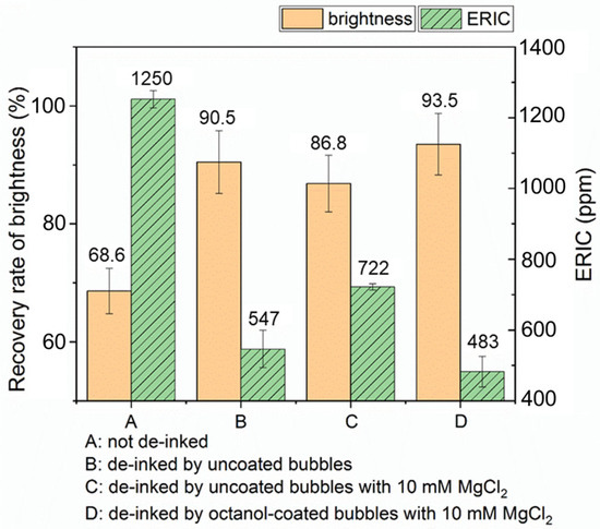
Figure 11.
Comparison of paper brightness and ERIC of paper pads that underwent different deinking methods. Recovery rate of brightness is with respect to ISO brightness of unprinted paper.
There can be concerns about product yield and fiber loss in flotation deinking, especially when one introduces oils such as 1-octanol that may have higher affinity for both the hydrophilic ink particles and the paper’s hydrophilic cellulose fibers compared to alkanes. Better paper brightness and lower ERIC value are desirable yet not at the cost of additional fiber loss. To assess this, we measured the amount of fiber lost in scenarios B and D. In the absence of 1-octanol (groups B1 through B3 in Table 2), a large amount of foam was created, leading to a significant amount of overflow that entrapped paper fibers physically and caused high fiber loss. In the presence of 1-octanol (groups D1 through D3 in Table 2), however, it is observed that the foamability of the system is slightly suppressed (yet still good enough to maintain a reasonable amount of the froth layer that can be skimmed off); therefore, less fiber material is rejected along with the froth. The suppression of aqueous foams by 1-octanol has been observed in the literature [47,48].
Table 2.
Comparison of conventional deinking and oil-assisted deinking. Groups B and D have the same condition as in Figure 11, and they are run in triplicate.
It is worth noting that the actual deinking process in the paper recycling industry is much more complicated than the simplified experiments we have presented here. For example, conventional flotation deinking, particularly with reuse of process water, may operate at a higher ionic strength than in our control scenario B due to the presence of salts, soaps, and acids or bases. Thus, scenario C above, containing added salt, may better mimic these ionic conditions than scenario B and serve as a useful comparison case. The significant improvement in scenario C with oil added (scenario D) suggests there is value in the use of oil-coated bubbles in situations where ionic strength is moderate (~10−2). The detachment of ink particles from paper fibers into water is another essential step but is outside the scope of our present investigation. Additionally, so that oil can be reused in the process, it needs to be separated from the ink and any other adsorbed or solubilized components. This will first require a more comprehensive understanding of the composition of the froth and an evaluation of separation processes including membranes, extraction, precipitation, or distillation. Other aspects of practical paper recycling include understanding the effects of pulp consistency, other contaminants (e.g., fillers and coatings), and mixed ink colors and types. We acknowledge that this initial exploration focusing on several parameters with one type of ink and one type of paper leaves an incomplete picture of how the proposed technology could be implemented in practice. Still, to the best of our knowledge, this is the first systematic study to evaluate the impact of system parameters in flotation deinking using both uncoated and oil-coated bubbles. More work will be necessary to help us understand the process more thoroughly in order to apply this method in manufacturing.
3. Materials and Methods
3.1. Materials
A hydrophilic inkjet ink (HPI-4060D) purchased from InkTec Co., Ltd. (Ansan-Si, Gyeonggi-do, Republic of Korea) was used in the deinking studies. InkTec HPI-4060D is a black, pigment-based ink. While the manufacturer has not specified the exact chemistry of the pigment, such inks are known to use carbon black as the pigment [49]. The product MSDS lists the pigment concentration as 0.1 to 5 wt.% [50]. Water-dispersible carbon black inks have been modified to possess surface carboxylate or sulfate species in their salt form. This is usually accomplished by chemical surface oxidation of the carbon black [51] or by use of physically adsorbed polymeric amphiphiles [52]. In addition to water, the MSDS available from InkTec also reports the presence of several humectants, such as glycerol (11 to 18 wt.%), ethoxylated glycerol (1 to 6 wt.%), and poly(ethylene oxide) (1 to 7 wt.%).
We selected a small set of oils that would spread at an air–water interface and had varying structure, polarity, and viscosity. Silicone oil (viscosity 10 cSt at 25 °C), decane (≥99%), hexadecane (≥99%), and paraffin oil (100–145 mPa s at 20 °C) were purchased from Sigma-Aldrich (St. Louis, MO, USA). 1-octanol was purchased from Tokyo Chemical Industry Co., Ltd. (Tokyo, Japan). Three alkanes with similarly low polarity but with viscosity that varied over two orders of magnitude allowed for an exploration of the influence of the oil spreading rate at the air–water interface. Silicone oil has a different chemical structure compared to the alkanes but has a similarly low dielectric constant. Finally, the use of 1-octanol allowed for an investigation of the effect of substituting a single polar hydroxyl group on an alkane, yielding a higher dielectric constant and viscosity than the alkane.
NaClO4 (98%) and NH4Cl (99.5–100.5%) were purchased from Sigma-Aldrich. NaCl and CaCl2 were purchased from Honeywell Fluka (Muskegon, MI, USA). MgCl2·6H2O, HCl, and NaOH were purchased from EMD Chemicals Inc. (Gibbstown, NJ, USA). Oleic acid was purchased from ICN Biomedicals Inc. (Costa Mesa, CA, USA). H2O2 was purchased from BDH Chemicals (Dubai, United Arab Emirates). Na2SiO3·5H2O was purchased from Fisher Scientific (Hampton, NH, USA). All chemicals were used as received. The water used was ultrapure DI water with a resistivity of 18.2 MΩ·cm (Barnstead). Recycled newsprint paper with an ISO brightness of 54.3% ± 3.0% was obtained from the Renewable Bioproducts Institute, Atlanta, GA, USA.
3.2. Miniaturized Deinking Test
For a quick and convenient first assay indicative of the deinking performance under different conditions, we used a miniaturized deinking test, as depicted in Figure 1. A diluted ink suspension was first prepared by adding 6 μL concentrated ink suspension into 10 mL DI water in a 20 mL glass vial. Then, the ionic strength and pH were adjusted using one of the above-mentioned salts and optionally HCl or NaOH. A small amount (0.5 mL) of one of the immiscible oils (silicone, decane, hexadecane, paraffin, or octanol) was subsequently added into the vial. Finally, the mixture was mechanically frothed using a rotor–stator homogenizer (IKA Ultra-Turrax T10, stator diameter of 8 mm and rotor diameter of 6.1 mm, IKA-Werke GmbH & Co. KG, Staufen im Breisgau, Germany) at 30,000 rpm for a total of 3 min (with a 20 s pause between three consecutive 1-minute intervals). The treated sample was then analyzed using a UV-vis spectrophotometer (Shimadzu UV-1800, Shimadzu, Kyoto, Japan) to determine the residual ink concentration in the unfoamed, liquid bottom part of the mixture. The absorbance at a 300 nm wavelength was related to the ink concentration based on the Beer–Lambert law. The ink particle removal efficiency was calculated as
Measurements were performed in triplicate and error bars were based on the standard deviation. Ink particle size and zeta potential were determined as a function of salt addition and pH by using diluted ink suspensions (~0.0025 vol.% solids) and a Malvern Zetasizer Nano ZS90 (Westborough, MA, USA). The z-average intensity-weighed mean diameter of particles was determined from three measurements.
3.3. Lab-Scale Deinking Test
Figure 12 shows the diagram of the lab-scale deinking flotation apparatus, which is similar to the experimental set up designed by Chen et al. [20]. It consists of a nebulizer (Shenzhen Fitconn Technology Co., Ltd., Shenzhen, China), a gas flow meter (Cole-Parmer Instrument Company, LLC., Vernon Hills, IL, USA), and a Denver D12 Laboratory Flotation Machine (Metso Co. Inc., Espoo, Finland). Oil is added into the nebulizer and is transformed into oil mist. The pressure of the compressed air was used to ensure a gas flow of ~15 L/min both in the presence and absence of oil mist. For oil-coated bubbles, the nebulizer power setting was adjusted to supply just enough oil to coat bubbles without also creating observable oil droplets in the water.
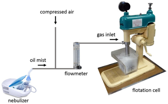
Figure 12.
Diagram of lab-scale deinking setup that includes a nebulizer to generate oil mist into which compressed air is introduced. After passing through a flowmeter, the oil-laden air is introduced into the flotation cell that contains the printed paper pulp to be deinked.
The lab-scale deinking test was performed following a standard procedure (Method 11: Assessment of Print Product Recyclability—Deinkability Test) from the International Association of the Deinking Industry (INGEDE) [53], as shown in Figure 3. The INGEDE standard printing pattern for deinking testing was first printed on newsprint paper by using the hydrophilic inkjet ink and a HP DESKJET 100 printer (HP, Palo Alto, CA, USA). Then, the paper was shredded into small pieces and oven-dried. A total of 200.0 g of the dried paper (200.0 g) was mixed with 400.0 g deinking solution (containing 1.20 g NaOH, 1.60 g oleic acid, and 6.26 g Na2SiO3·5H2O) and 630.0 g hard water (containing 0.30 g CaCl2·2H2O). The mixture was pulped using a food mixer (KitchenAid Artisan KSM150PSER 5, KitchenAid, Joseph, MI, USA) in a 45 °C water bath for 2 min, followed by the addition of 100.0 g deionized water and 1.40 g H2O2 and another 18 min of pulping. After pulping, the mixture was conditioned: 302.7 g pulp mixed with 600 mL hard water (containing 0.28 g CaCl2·2H2O) was conditioned in a 45 °C hot water bath for 60 min. Subsequently, the conditioned pulp was mixed with 4.5 L hard water (containing 2.12 g CaCl2·2H2O), resulting in a mixture with ~45 g solids and ~5360 g liquid. Finally, flotation was performed in the flotation machine for 15 min per sample. Oil-coated bubble flotation was performed in a similar fashion to conventional air bubble flotation, except that the oil mist was introduced into the system. Froth scraping was performed manually, approximately once per minute. After flotation, paper pads were created by filtering the deinked pulp, and these were air-dried for at least 24 h. The ISO paper brightness and ERIC were measured using a ColorTouch 2 instrument (Technidyne Co. Inc., New Albany, IN, USA). Measurements were performed in triplicate, and error bars were based on the standard deviation.
4. Conclusions
Managing the deinking of paper printed with hydrophilic inks commonly used in inkjet printing continues to be a challenge faced during paper recycling that relies on traditional air-bubble flotation. In this study, flotation deinking of paper using both uncoated and oil-coated bubbles was performed with miniaturized homogenized samples and lab-scale flotation deinking testing. Parameters including oil type, salt type, salt concentration, and pH were systematically varied. We found that oil-coated bubble flotation often dramatically outperforms standard flotation with uncoated bubbles; the highest ink removal efficiency was observed in systems containing multivalent salts at a low pH when using bubbles coated with 1-octanol. This study provides an initial exploration of the effects of several parameters impacting the recovery of hydrophilic ink particles from paper by using oil-coated bubble flotation, and the results are expected to trigger additional studies of this approach within paper recycling and other separations. With the new understanding of system parameter effects, future studies can be designed to develop and test mechanistic hypotheses.
Supplementary Materials
The following supporting information can be downloaded at: https://www.mdpi.com/article/10.3390/recycling11010012/s1; numerical data used to generate plots.
Author Contributions
Conceptualization, S.W., J.C.M. and S.H.B.; methodology, S.W., J.C.M. and S.H.B.; formal analysis, S.W., X.Z., X.D., J.C.M. and S.H.B.; investigation, S.W., X.Z., X.D., J.C.M. and S.H.B.; resources, J.C.M. and S.H.B.; data curation, S.W.; writing—original draft preparation, S.W.; writing—review and editing, S.W., J.C.M. and S.H.B.; visualization, S.W.; supervision, J.C.M. and S.H.B.; project administration, J.C.M. and S.H.B.; funding acquisition, J.C.M. and S.H.B. All authors have read and agreed to the published version of the manuscript.
Funding
This research was funded by a Graduate Fellowship from the Renewable Bioproducts Institute at the Georgia Institute of Technology and from the National Science Foundation (CBET-1706475).
Data Availability Statement
The original contributions presented in this study are included in the Supplementary Material. Further inquiries can be directed to the corresponding author.
Conflicts of Interest
The authors declare no conflicts of interest.
Abbreviations
The following abbreviations are used in this manuscript:
| ERIC | effective residual ink concentration |
| INGEDE | International Association of the Deinking Industry |
| ISO | International Standards Organization |
References
- Fuerstenau, M.C.; Jameson, G.J.; Yoon, R.-H. (Eds.) Froth Flotation: A Century of Innovation; SME: Littleton, CO, USA, 2007. [Google Scholar]
- Houot, R. Beneficiation of iron-ore by flotation—Review of industrial and potential applications. Int. J. Miner. Process. 1983, 10, 183–204. [Google Scholar] [CrossRef]
- Feng, D.; Aldrich, C. Effect of particle size on flotation performance of complex sulphide ores. Miner. Eng. 1999, 12, 721–731. [Google Scholar] [CrossRef]
- Rubio, J.; Souza, M.L.; Smith, R.W. Overview of flotation as a wastewater treatment technique. Miner. Eng. 2002, 15, 139–155. [Google Scholar] [CrossRef]
- Polat, H.; Erdogan, D. Heavy metal removal from waste waters by ion flotation. J. Hazard. Mater. 2007, 148, 267–273. [Google Scholar] [CrossRef] [PubMed]
- Ramaswamy, B.; Kar, D.D.; De, S. A study on recovery of oil from sludge containing oil using froth flotation. J. Environ. Manag. 2007, 85, 150–154. [Google Scholar] [CrossRef]
- Pal, R.; Masliyah, J. Oil-recovery from oil in water emulsions using a flotation column. Can. J. Chem. Eng. 1990, 68, 959–967. [Google Scholar] [CrossRef]
- Hernandez, H.; Gomez, C.O.; Finch, J.A. Gas dispersion and de-inking in a flotation column. Miner. Eng. 2003, 16, 739–744. [Google Scholar] [CrossRef]
- Kemper, M. State-of-the-art and new technologies in flotation deinking. Int. J. Miner. Process. 1999, 56, 317–333. [Google Scholar] [CrossRef]
- Hunter, T.N.; Pugh, R.J.; Franks, G.V.; Jameson, G.J. The role of particles in stabilising foams and emulsions. Adv. Colloid Interface Sci. 2008, 137, 57–81. [Google Scholar] [CrossRef]
- Cheng, G.; Peng, Y.; Duan, P.; Li, E.; Lv, C.; Wang, X.; Cheng, F. Sustainable Desulfurization of Fine High-Sulfur Coal via Flotation-Electrochemical Method. Miner. Eng. 2025, 233, 109571. [Google Scholar] [CrossRef]
- Asimi Neisiani, A.; Saneie, R.; Mohammadzadeh, A.; Wonyen, D.G.; Chehreh Chelgani, S. Polysaccharides-based pyrite depressants for green flotation separation: An overview. Int. J. Min. Sci. Technol. 2023, 33, 1229–1241. [Google Scholar] [CrossRef]
- Liu, Y.; DiFoggio, R.; Sanderlin, K.; Perez, L.; Zhao, J. Measurement of density and viscosity of dodecane and decane with a piezoelectric tuning fork over 298–448K and 0.1–137.9MPa. Sens. Actuators A Phys. 2011, 167, 347–353. [Google Scholar] [CrossRef]
- Ben, Y.X.; Dorris, G. Is deinkability of inkjet prints an issue? TAPPI J. 2011, 10, 17–27. [Google Scholar] [CrossRef]
- Chen, F.; Finch, J.A.; Distin, P.A.; Gomez, C.O. Air assisted solvent extraction. Can. Metall. Quart. 2003, 42, 277–280. [Google Scholar] [CrossRef]
- Erol, M.; Colduroglu, C.; Aktas, Z. The effect of reagents and reagent mixtures on froth flotation of coal fines. Int. J. Miner. Process. 2003, 71, 131–145. [Google Scholar] [CrossRef]
- Liu, J.; Mak, T.; Zhou, Z.; Xu, Z. Fundamental study of reactive oily-bubble flotation. Miner. Eng. 2002, 15, 667–676. [Google Scholar] [CrossRef]
- Zhou, F.; Wang, L.; Xu, Z.; Liu, Q.; Chi, R. Reactive oily bubble technology for flotation of apatite, dolomite and quartz. Int. J. Miner. Process. 2015, 134, 74–81. [Google Scholar] [CrossRef]
- Wang, S.W.; Tao, X.X. Comparison of flotation performances of low rank coal in air and oily bubble processes. Powder Technol. 2017, 320, 37–42. [Google Scholar] [CrossRef]
- Chen, S.; Tang, L.; Tao, X.; He, H.; Yang, Z.; Chen, L. Exploration on the mechanism of oily-bubble flotation of long-flame coal. Fuel 2018, 216, 427–435. [Google Scholar] [CrossRef]
- Wallwork, V.; Xu, Z.H.; Masliyah, J. Bitumen recovery with oily air bubbles. Can. J. Chem. Eng. 2003, 81, 993–997. [Google Scholar] [CrossRef]
- Su, L.; Xu, Z.; Masliyah, J. Role of oily bubbles in enhancing bitumen flotation. Miner. Eng. 2006, 19, 641–650. [Google Scholar] [CrossRef]
- Tarkan, H.M.; Finch, J.A. Air-assisted solvent extraction: Towards a novel extraction process. Miner. Eng. 2005, 18, 83–88. [Google Scholar] [CrossRef]
- Tarkan, H.M.; Gelinas, S.; Finch, J.A. Measurement of thickness and composition of a solvent film on a bubble. J. Colloid Interface Sci. 2006, 297, 732–737. [Google Scholar] [CrossRef] [PubMed]
- Maiolo, J.; Pelton, R. Aerosol-enhanced flotation—A possible approach to improved flotation deinking. J. Pulp Pap. Sci. 1998, 24, 324–328. [Google Scholar]
- Gomez, C.O.; Acuna, C.; Finch, J.A.; Pelton, R. Aerosol-enhanced flotation deinking of recycled paper—Silicone oil offers an effective way of forming a layer on the bubble surface. Pulp Pap.-Can. 2001, 102, 28–30. [Google Scholar]
- Wang, S.C.; Zhang, Y.; Meredith, J.C.; Behrens, S.H.; Tripathi, M.K.; Sahu, K.C. The dynamics of rising oil-coated bubbles: Experiments and simulations. Soft Matter 2018, 14, 2724–2734. [Google Scholar] [CrossRef]
- Zhang, Y.; Wu, J.; Wang, H.; Meredith, J.C.; Behrens, S.H. Stabilization of liquid foams through the synergistic action of particles and an immiscible liquid. Angew. Chem. Int. Ed. Engl. 2014, 53, 13603–13607. [Google Scholar] [CrossRef]
- Zhang, Y.; Allen, M.C.; Zhao, R.Y.; Deheyn, D.D.; Behrens, S.H.; Meredith, J.C. Capillary foams: Stabilization and functionalization of porous liquids and solids. Langmuir 2015, 31, 2669–2676. [Google Scholar] [CrossRef]
- Zhang, Y.; Wang, S.C.; Zhou, J.R.; Benz, G.; Tcheimou, S.; Zhao, R.Y.; Behrens, S.H.; Meredith, J.C. Capillary foams: Formation stages and effects of system parameters. Ind. Eng. Chem. Res. 2017, 56, 9533–9540. [Google Scholar] [CrossRef]
- Israelachvili, J.N. Intermolecular and Surface Forces, 3rd ed.; Elsevier Science & Technology: Amsterdam, The Netherlands, 2011; Chapter 6.7. [Google Scholar]
- Deodhar, S.; Thampi, S.P.; Basavaraj, M.G. Drops spreading on fluid surfaces: Transition from Laplace to Marangoni regime. Phys. Rev. Fluids 2021, 6, L112001. [Google Scholar] [CrossRef]
- Engineering ToolBox. Available online: https://www.engineeringtoolbox.com (accessed on 1 April 2020).
- Dortmund Data Bank. Available online: http://www.ddbst.com (accessed on 1 July 2025).
- Maryott, A.A.; Smith, E.R. Table of Dielectric Constants of Pure Liquids; National Bureau of Standards: Washington, DC, USA, 1951; Volume NBS Circular 514.
- Hardy, R.C. Viscosity of n-hexadecane. J. Res. Natl. Bur. Stand. 1958, 61, 433–436. [Google Scholar] [CrossRef]
- Hoffmann, M.M.; Gonzalez, A.A.; Huynh, M.T.; Miller, K.K.; Gutmann, T.; Buntkowsky, G. Densities, Viscosities, and Self-Diffusion Coefficients of Octan-1-ol and Related Ether-Alcohols. J. Chem. Eng. Data 2024, 69, 2688–2699. [Google Scholar] [CrossRef]
- Gregory, J. Monitoring particle aggregation processes. Adv. Colloid Interface Sci. 2009, 147, 109–123. [Google Scholar] [CrossRef]
- Elimelech, M.; Gregory, J.; Jia, X.; Williams, R.A. Particle Deposition & Aggregation: Measurement, Modelling and Simulation; Butterworth-Heinemann: Oxford, UK, 1995; Chapter 6.2. [Google Scholar]
- An, Y.; Sun, K.; Qiu, Y.; Zhang, L. Specific Cation Effect on the Flotation of Graphite. Minerals 2022, 12, 1070. [Google Scholar] [CrossRef]
- Choi, J.; Choi, S.Q.; Park, K.; Han, Y.; Kim, H. Flotation behaviour of malachite in mono- and di-valent salt solutions using sodium oleate as a collector. Int. J. Miner. Process. 2016, 146, 38–45. [Google Scholar] [CrossRef]
- Han, M.Y.; Ahn, H.J.; Shin, M.S.; Kim, S.R. The effect of divalent metal ions on the zeta potential of bubbles. Water Sci. Technol. 2004, 50, 49–56. [Google Scholar] [CrossRef] [PubMed]
- dos Santos, A.P.; Diehl, A.; Levin, Y. Surface Tensions, Surface Potentials, and the Hofmeister Series of Electrolyte Solutions. Langmuir 2010, 26, 10778–10783. [Google Scholar] [CrossRef]
- López-León, T.; Santander-Ortega, M.J.; Ortega-Vinuesa, J.L.; Bastos-González, D. Hofmeister Effects in Colloidal Systems: Influence of the Surface Nature. J. Phys. Chem. C 2008, 112, 16060–16069. [Google Scholar] [CrossRef]
- Schulze, H. Schwefelarsen in wässriger Lösung. J. Prakt. Chem. 1882, 25, 431–452. [Google Scholar] [CrossRef]
- Hardy, W.B. A preliminary investigation of the conditions which determine the stability of irreversible hydrosols. Proc. R. Soc. Lond. 1900, 66, 110–125. [Google Scholar] [CrossRef]
- Liu, Y.; Zhu, Z. Alkyl Alcohols as Defoamers to Remove Foam Generated by Partially Alcoholyzed Polyvinyl Alcohol for Warp Sizing. AATCC J. Res. 2019, 6, 15–21. [Google Scholar] [CrossRef]
- Pugh, R.J. Foaming, foam films, antifoaming and defoaming. Adv. Colloid Interface Sci. 1996, 64, 67–142. [Google Scholar] [CrossRef]
- Shakhnovich, A.; Belmont, J. Pigments for inkjet applications. In The Chemistry of Inkjet Inks; Magdassi, S., Ed.; World Scientific: Singapore, 2010; pp. 101–122. [Google Scholar]
- HPI-4060D Material Safety Data Sheet; Inktec: Ansan, Republic of Korea, 2014.
- Nakata, H.; Horii, T. Aqueous Carbon Black Dispersion and Process for Producing the Same. No. EP1967560B1, 2 February 2011. [Google Scholar]
- Yoon, C.; Choi, J.-H. Synthesising polymeric dispersants to apply to carbon black pigmented mill bases for use in ink-jet inks. Color. Technol. 2020, 136, 60–74. [Google Scholar] [CrossRef]
- INGEDE Method 11. Available online: https://www.ingede.com/ingindxe/methods/ingede-method-11-2018.pdf (accessed on 1 May 2020).


Disclaimer/Publisher’s Note: The statements, opinions and data contained in all publications are solely those of the individual author(s) and contributor(s) and not of MDPI and/or the editor(s). MDPI and/or the editor(s) disclaim responsibility for any injury to people or property resulting from any ideas, methods, instructions or products referred to in the content. |
© 2026 by the authors. Licensee MDPI, Basel, Switzerland. This article is an open access article distributed under the terms and conditions of the Creative Commons Attribution (CC BY) license.