Article

A Polyacrylonitrile Shutdown Film for Prevention of Thermal Runaway in Lithium-Ion Cells

by
Jonathan Peter Charles Allen
,
Marcin Mierzwa
,
Denis Kramer
,
Nuria Garcia-Araez
and
Andrew L. Hector
*
School of Chemistry, University of Southampton, Highfield, Southampton SO17 1BJ, UK
*
Author to whom correspondence should be addressed.
Batteries 2023, 9(5), 282; https://doi.org/10.3390/batteries9050282
Submission received: 6 March 2023 / Revised: 12 May 2023 / Accepted: 13 May 2023 / Published: 21 May 2023
(This article belongs to the Special Issue Thermal Management System for Lithium-Ion Batteries)

Abstract

:
The electrodeposition of a polymer (polyacrylonitrile, PAN) is used to reduce the risk of thermal runaway in lithium-ion batteries, which is the most important cause of battery accidents and fires. PAN was electrodeposited on a graphite battery electrode, using cyclic voltammetry or chronoamperometry, in a solution with acrylonitrile as the solvent. The electrodeposited PAN film was characterised by Raman spectroscopy, microscopy, energy dispersive X-ray analysis, and thermogravimetric analysis, and it was found that the film thickness could be controlled by the amount of charge passed in the electrochemical experiments. The PAN-coated graphite battery electrode was then tested in lithium half-cells, obtaining capacities close to the uncoated graphite sample (ca. 360 mA h g−1) for thin (<10 µm) polymer coatings at 25 °C. Interestingly, for thicker polymer coatings (>20 µm) it was found that the capacity decreased drastically as the temperature increased beyond 80 °C. Such suppression in capacity has applications for thermal runaway protection since the electrochemical reactions of degradation of the electrolyte in contact with the electrode are the root cause of the thermal runaway process. Further work should look into alternative polymer and liquid electrolyte formulations to achieve the desired suppression of electrochemical capacity at high temperatures while retaining high capacities at the operational temperature range.

1. Introduction

Lithium-ion batteries are the battery of choice in many devices, such as electric vehicles and portable electronics, so methods to increase their safety are extremely important. Thermal runaway is, by far, the greatest cause of accidents in battery packs [1,2]. The process of thermal runaway occurs when the rate of heat generation, triggered by mechanical/thermal/electrical abuse, is greater than the heat dissipation. Increasing heat generation within a battery leads to higher rates of exothermic reaction, resulting in even greater amounts of heat generation [3]. As a result, battery temperature increases uncontrollably, accelerating battery degradation, which can lead to a fire or explosion. Effective thermal management can be pursued using systems external to a battery pack; however, as heat flux occurs due to battery charge-discharge reaction, thermal management can also be pursued within the materials of a lithium-ion cell [3].
Battery electrode materials are constantly being developed to improve their safety and overall performance [4,5]. One method of safety improvement is via the implementation of functional materials in addition to the battery electrodes, of which a variety have been studied to improve the safety of lithium-ion batteries [6,7,8,9,10]. Particularly effective has been the development of thermal shut-down separators [11,12,13], whose porosity closes as the temperature of the battery increases, permanently stopping ion transport; ions are unable to reach the electrode-electrolyte interface, halting the battery electrochemistry. This removes one potential source of heat generation. Unfortunately, further heating may still occur which could trigger thermal runaway. This can come internally in the form of gas pressure build-up from the products of thermal degradation or chemical side-reactions with these products. However, external causes can also pose a problem, such as excessive currents or heat sources [3]. Consequently, it is widely agreed that securing battery safety requires the combination of several safety approaches so that if one approach fails the battery would still be protected by other approaches. For instance, venting of flammable gases to reduce pressures alongside a thermal fuse to cut-off the external current to at-risk cells.
Materials with resistance that drastically increases with temperature (positive temperature coefficient of resistivity, or PTCR, materials) have been developed to improve battery safety, including ceramic materials [14] and thermoresponsive polymers [15,16,17,18,19,20,21,22,23]. An alternative approach using thermoresponsive polymer microspheres that melt as the battery heats, stopping the ion flow and shutting down the battery, has also been reported [24,25,26]. These materials, in essence, have similar operations to thermal fuses acting to reduce the current to the electrochemical system as temperature increases. However, these materials are present at the source of the electrochemical reaction within the cell allowing for rapid response to increases in temperature.
In this work, we report for the first time the application of electrodeposited polymers to achieve battery shutdown. The working principle is similar to thermal shutdown separators with the exception that the polymer is directly coated onto one of the electrodes. As a result, the thickness and morphology of the polymer coating can be controlled by tuning the electrochemical conditions for the electrodeposition. We also demonstrate that, upon heating the battery, the polymer coating induces the battery shutdown (as seen by a drastic decrease in capacity). Sister batteries run under the same conditions but without polymer coating and still deliver a high capacity; this is undesirable as the high electrochemical activity of the battery at high temperatures could promote a thermal runaway event.

2. Experimental

2.1. Materials

The full list of materials used is given below in Table 1. Information on the usage of each material and the component they formed is also provide along with information on suppliers and their locations.

2.2. Graphite Battery Electrode Preparation

The substrates used for the electrodeposition of PAN were graphite battery electrodes and they were prepared using an ink-casting method. For the ink preparation, 10% by weight PVDF was first dissolved in NMP. Graphite, carbon black, and the PVDF solution were then weighed to produce a mixture of mass ratio of 94:3:3 based on the solid components. Additional NMP was added to reduce viscosity until the mixture contained 60% by weight of NMP. A Thinky planetary mixer was used to blend the ink mixture for 15 min at 2000 rpm to produce the composite ink. A coating of the ink was applied to a copper foil, which had been polished using alumina powder of increasing fineness (from 1 to 0.3, and finally 0.05 µm). A TQC Sheen doctor blade was used to perform the coating, the thickness of the coating was set to 0.25 mm and the ink was spread at a speed of 200 mm s−1. The ink was dried at 80 °C for 2 to 3 h in a vacuum oven. Electrodes were sized to 20 × 20 mm and pressed with a manual hydraulic press at 10 tonnes.

2.3. PAN Electrodeposition

Distillation of acrylonitrile was performed at 90 to 100 °C with a nitrogen environment using a drying agent of CaH2 with a reflux of 8 h before collection. Tetrabutylammonium perchlorate ([Bu4N][ClO4]) was vacuum dried at ambient temperature for 24 h. A 0.05 mol dm−3 [Bu4N][ClO4] in acrylonitrile solution was prepared under nitrogen.
A three-electrode arrangement was used for electrodeposition studies. A graphite battery electrode formed the working electrode, platinum gauze the counter, and a silver wire was used as a pseudo reference. This was set up within a Teflon deposition cell with a 14 mm diameter deposition window a Teflon O-ring over the working electrode surface. A volume of 10 mL of electrolyte was added to the Teflon cell which was then saturated with oxygen by bubbling through a sparger for 15 min. The reference and counter electrodes were then placed into the electrolyte and electrodepositions were performed with a Biologics SP-150 potentiostat, employing EC-Lab software. This Teflon cell arrangement was used in a previous electrodeposition study of PAN, which discussed the practicality of the Teflon cell for such depositions and included a preliminary discussion of a cyclic voltammogram and optical microscopy [27]. However, no data were presented on Raman or SEM-EDS to verify PAN deposition nor were TGA studies performed on the electrodeposit. Further studies to tailor film thicknesses or test electrodes in a lithium half-cell were also absent. Work within this article provides all this additional information as proof of concept for PAN electrodepositions onto practical graphite battery electrodes within lithium half-cells.
Two techniques were used for the electrodeposition of PAN: cyclic voltammetry and chronoamperometry. Cyclic voltammetry scans were performed to understand the electrochemistry behind the depositions, using a scan rate of 50 mV s−1 in the potential window from 0.0 to −3.0 V vs. Ag. Chronoamperometry studies were utilised to accurately modify the film thickness of the electrodeposits; several different potentials were used to identify the electrochemical behaviour over a potential range, then timescales were varied to achieve the required film thicknesses. Firstly, potential values applied were varied between −0.7 and −3.0 V vs. Ag, with an electrodeposition time of 100 s. Then, different time values were subsequently studied using an applied potential of −3.0 V vs. Ag.
Electrode samples were air-dried following electrodepositions for 24 h. They were then washed in ethanol for 10 min to remove the remaining electrolyte and oligomers, followed by further air drying for 24 h. The mass of electrodes was recorded before and after deposition, and film thicknesses were measured using a digital micrometer.

2.4. Lithium Half-Cell Assembly and Electrochemical Testing

Electrodes of 11 mm diameter were punched from the 14 mm diameter electrodeposited PAN of the graphite electrode substrates with a precision punch (EL-CELL, EL-Cut). The battery graphite electrode (either uncoated or coated with electrodeposited PAN) was used as the working electrode in Swagelok cells. The working electrodes were positioned against counter-reference electrodes of lithium metal foil of 11 mm diameter in a half-cell arrangement. Two 12 mm diameter glass fibre separators were sandwiched between the working and counter-reference electrodes and wetted with 200 μL of LP57 electrolyte. Copper plungers were used for both electrodes as current collectors in the Swagelok cell. Room temperature studies were performed with Swagelok cells with PFA bodies. For elevated temperature studies, Swagelok cells of polymer materials can expand at temperature, and this may affect the seal of the ferrules within the cell and ingress of air. Hence, Swagelok cells of aluminium were used at higher temperatures. Aluminium Swageloks were lined with 125 μm thick FEP film to insulate the inner cell body and prevent a short-circuit between the electrodes.
The Swagelok cells were assembled under the argon environment of a Belle Technology Ltd. glovebox. A Buchi glass oven B-585 was used to dry electrode and separator materials at 120 °C under vacuum for 24 h. These materials were then transported to the glovebox. The same Buchi ovens were used to dry graphite battery composite electrodes with PAN films at ambient temperature under vacuum for an extended time of 72 h; this was done at ambient temperature to avoid any annealing or thermal deformation of the PAN films.
Constant current cycling of the Swagelok cells was performed using either a BCS-805 battery cycler with BT-Lab software or an SP-150 potentiostat (Biologics, Grenoble, France) with EC-Lab software. Current values were kept to a C-rate of C/10. Room temperature studies were repeated for 10 cycles and the potential window was kept within 0.005 and 1.5 V vs. Li/Li+ in half-cells. The temperature was maintained at 25 °C by making use of an environmental chamber (Memmert, Schwabach, Germany, IPP 55 Plus), and the cells were placed inside the chamber as cycling was performed.
Elevated temperatures were achieved by employing a Genlab Classic oven (Agar Scientific, Stansted, UK, MINO/6), allowing for the cycling of cells at set temperatures. To prevent interference with the electric signal due to the high temperatures and equipment, a coaxial cable insulated with FEP polymer was employed for reliable elevated temperature performance up to 200 °C. Two constant current charge-discharge cycles were performed at each temperature interval at a current C-rate of C/10. The intervals of temperature employed were: 25, 60, 80, 100, and 120 °C. A K-type thermocouple was used to monitor the temperature of the cycling chamber.

2.5. Characterisation

A Philips XL30 ESEM was used to take scanning electron micrographs (SEM images) of the electrodeposited PAN with energy-dispersive X-ray spectroscopy (EDX) from a Thermo Fisher Scientific (Waltham, MA, USA) Ultra Dry 10 mm2 detector. Samples were mounted onto stubs and secured with double-backed sticky conductive carbon tape and then transferred to the microscope chamber. Secondary electron imaging captured sample topography and EDX measurements were used to identify ratios of carbon and nitrogen within the polymer films.
A 785 nm Renishaw inVia confocal Raman microscope was employed to take the Raman spectra of the polymer films and measurements were taken between 3500 and 150 cm−1 where characteristic PAN peaks are identifiable [28,29]. Laser power was set to 1% and data was gathered over a total of three accumulations. Polymer films that had been electrodeposited onto graphite battery electrode substrates were placed under the Raman laser source.
A Netzsch TG 209 F1 Libra was used for thermogravimetric analysis (TGA) studies. Samples were powdered and placed within alumina crucibles that would then be transferred to the TGA chamber. A flow of argon gas at 20 mL min−1 maintained an inert atmosphere within the TGA chamber. A temperature gradient of 2 °C min−1 was applied from 25 to 250 °C. TGA studies were performed for the materials of the graphite-composite electrode inks: graphite powder active material, carbon black powder conductive additive, and PVDF binder. TGA was performed with a commercially available PAN powder and compared with PAN electrodeposited onto a copper substrate. Samples of the PAN electrodeposit were scratched from the substrate surface for transfer to the TGA alumina crucibles.

3. Results and Discussion

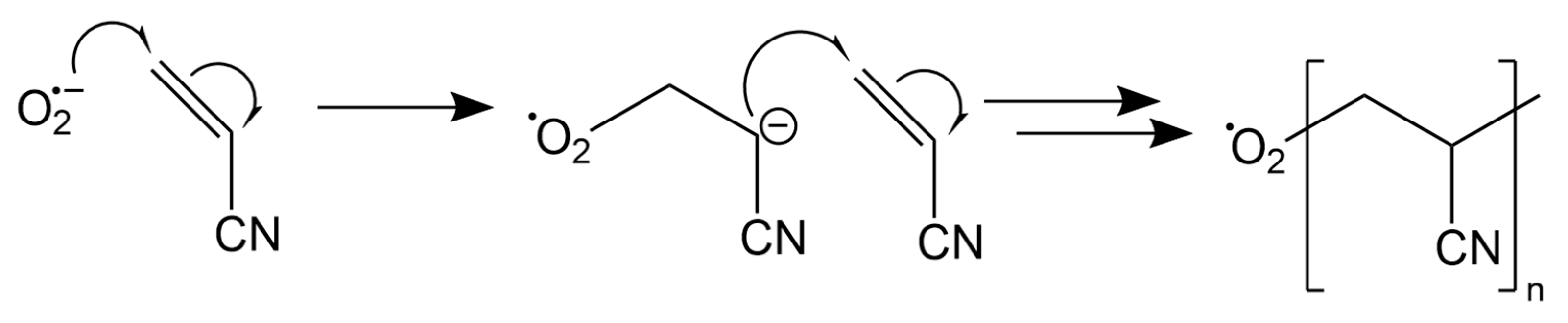
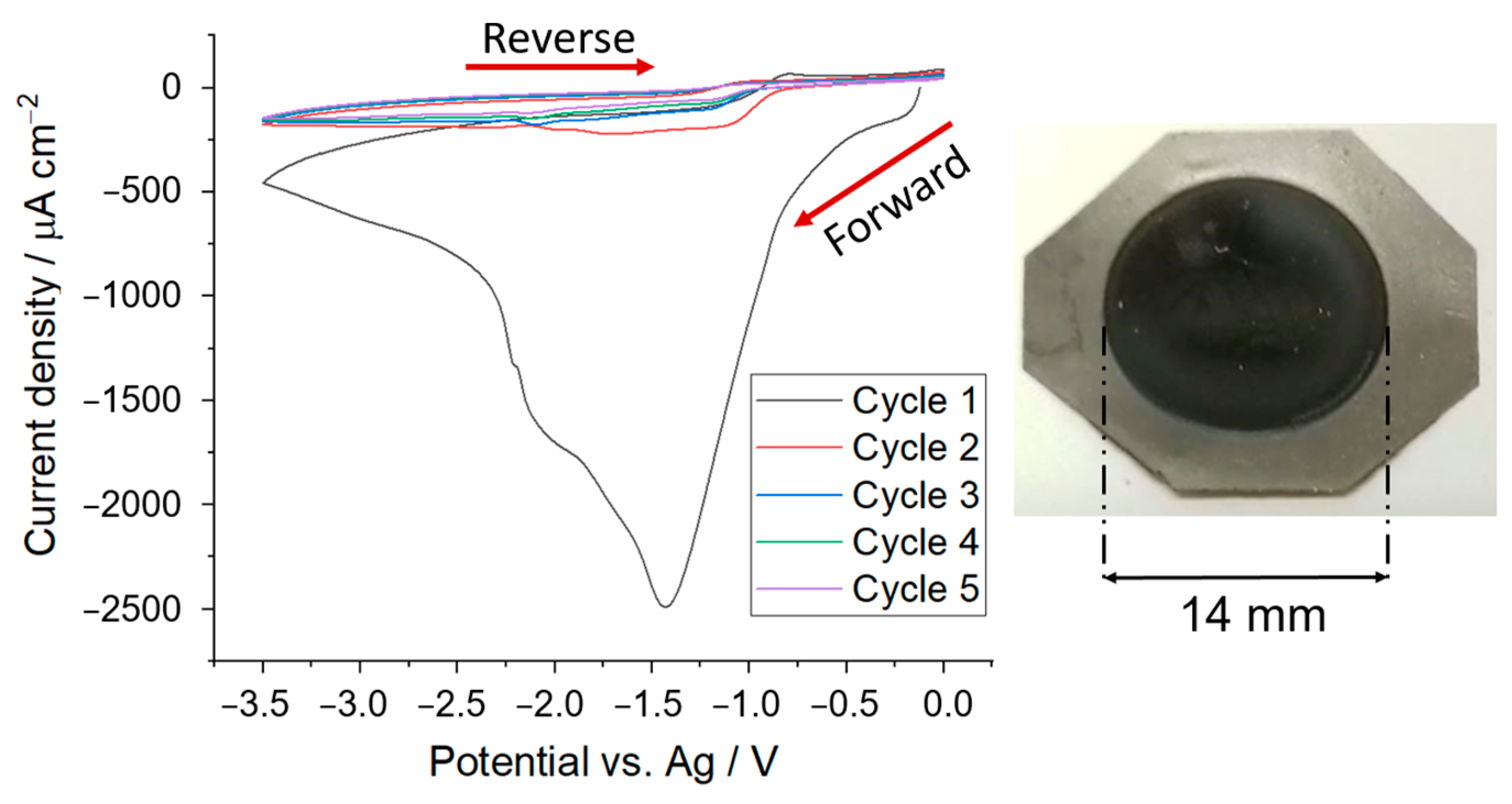
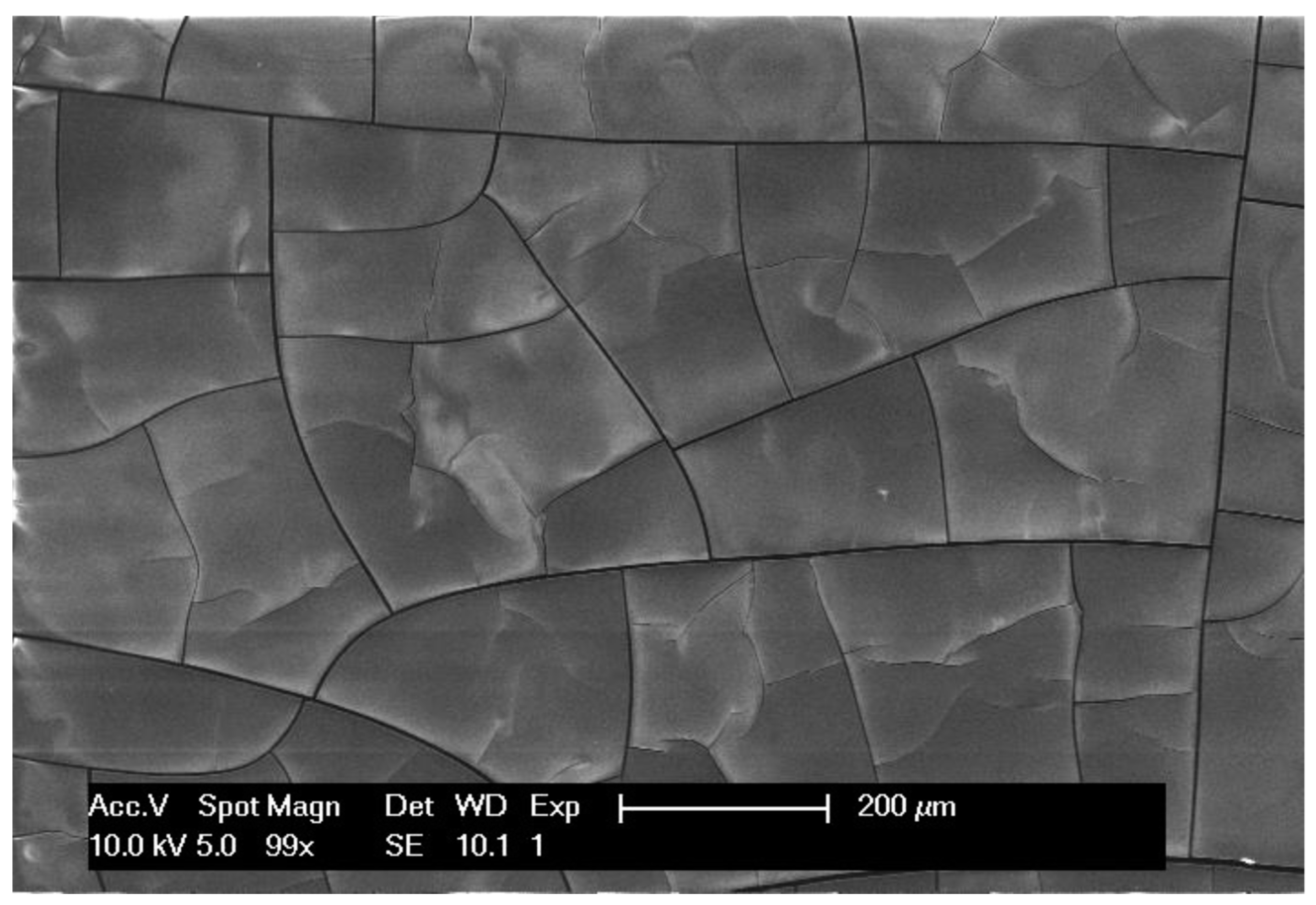
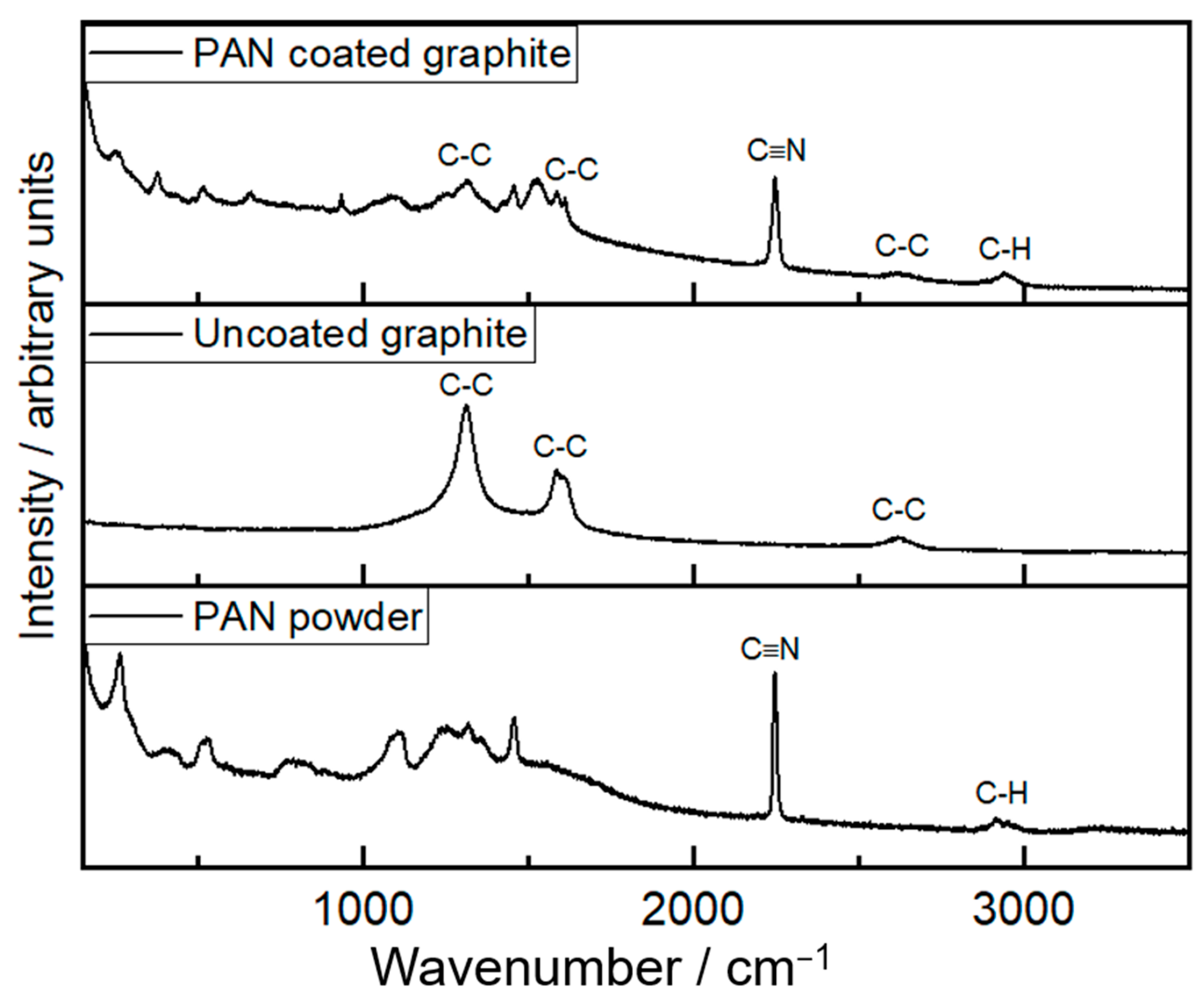
3.1. Formation of Polymer Coating on Graphite Battery Electrode by Electrodeposition

To demonstrate the concept of employing an electrodeposited polymer coating with thermal shutdown properties to improve battery safety, we selected the electrodeposition of polyacrylonitrile (PAN). PAN electrodeposition onto a variety of electrode materials was demonstrated in the 1980s by Lécayon and co-workers [30,31,32], with electrodeposition being possible on surfaces provided they were electronically conductive. It was, therefore, a reasonable assumption that PAN electrodeposition would be possible onto a range of anode and cathode materials provided the material itself is conductive or part of a conductive composite. More recently, Lacey and co-workers demonstrated the application of the electrodeposition of PAN as a method to form the separator in thin-film batteries [28] and in 3D batteries [29]. It was shown that the electrodeposition enabled the fast formation of uniform polymer thin films and that the amount of polymer deposited could be controlled by the charge involved in the electrodeposition process. It was also shown that the electrodeposition was facilitated by the presence of O2, the importance of which was attributed to the formation of superoxide species from the reduction of O2; these superoxide species then initiated the polymerisation of acrylonitrile [29]. Superoxide anions are nucleophiles that react with Michael acceptors that are sufficiently active (in acrylonitrile this is provided by the electron-withdrawing vinyl group). The polymerisation of acrylonitrile via the electronically reduced superoxide species is shown in Figure 1.
In our work, we employ the conditions reported by Lacey and co-workers for the electrodeposition of PAN in the presence of O2 [29]. Following their work, we employ acrylonitrile as the solvent as well as the monomer for the formation of PAN, since this facilitates the rapid deposition of the polymer. However, in our work, we employ a graphite battery electrode as the substrate for the electrodeposition rather than glassy carbon or gold disc electrode materials. Moreover, we employ an Ag pseudo-reference electrode instead of an Ag/Ag+ electrode, to avoid possible Ag+ contamination.
Figure 2 shows the cyclic voltammogram obtained with the graphite battery electrode in an O2-saturated acrylonitrile solution. The graphite battery electrode was made by tape casting a viscous ink containing graphite powder, carbon conductive additive, and PVDF binder in a 94:3:3 mass ratio. The voltammogram in Figure 2 shows a peak current at potentials close to −1.5 V vs. Ag, in agreement with the previous work by Lacey and co-workers [29]. The current then decreases markedly and remains low in the following cycles as expected for a passivated electrode surface, again in agreement with previous work [29]. The electrodeposited PAN is an insulator, but when impregnated with electrolyte, as in the present case, PAN becomes a gel-polymer electrolyte [33,34,35,36,37]. The decay in current with time (that is, with each cycle) in the cyclic voltammetry experiments is thus due to the increased ionic resistance that is built upon by the formation of the polymer coating on the electrode. A photo of the electrode after the deposition is included in Figure 2, showing that the polymer coating is transparent. The mass of the PAN electrodeposit in this experiment was 9.3 mg cm−2.
The polymer coating on the graphite battery electrode was further characterised by SEM, EDX, and Raman measurements. The SEM image in Figure 3 shows that the polymer film exhibits distinct cracks, which are likely to be formed in the drying process prior to the introduction of the electrode in the SEM (after it has been extracted from the electrochemical cell). The carbon-to-nitrogen ratio measured by EDX (70 wt.% and 30 wt.%, respectively) is close to what is expected for polyacrylonitrile (68 wt.% and 26 wt.%).
The Raman spectra of the polymer coating on the graphite battery electrode further confirm that the polymer formed is PAN, as shown in Figure 4. The characteristic signals from Raman for the C≡N group at 2250 cm−1 and C-H alkyl groups at 3000 cm−1 in PAN [38] are clearly observed. In addition, the characteristic Raman signals of graphite at 1600 cm−1 and 1350 cm−1 [39] are weaker for the PAN-coated graphite electrode, compared to the uncoated one, as expected for the lower penetration of the Raman laser to the graphite substrate in the presence of the polymer coating. The Raman spectra for electrodeposited PAN on graphite also show additional features at lower wavenumber that are likely due to impurities, as previously found [29].
Finally, the TGA of the PAN electrodeposit was performed to evaluate its thermal stability. For that purpose, a PAN electrodeposition was performed on a copper substrate to avoid contamination by the graphite battery electrode materials, after which the PAN electrodeposit was scratched off and then characterised by TGA. As shown in Figure 5, the loss of mass from the PAN electrodeposit was larger than that of a commercial PAN powder, and also larger than the variation observed for any of the components that make a graphite battery electrode (graphite, conductive carbon additive, and PVDF binder). No substantial chemical impurities were identified in the PAN electrodeposit with the Raman in Figure 4 and so it was likely that the loss of mass was from materials of similar chemical composition. This is likely to be shorter chain oligomers with boiling points closer to the 77 °C boiling point of the acrylonitrile monomers from which the PAN was electrodeposited; this results in the greater mass loss observed past 120 °C. However, mass loss for the electrodeposited PAN up to 120 °C was only 0.49% of the initial mass, and even at 150 °C the change was only 1.1%. It was thus concluded that the thermal stability of the electrodeposited PAN was sufficient up to 120 °C and in all subsequent experiments the temperature was kept ≤120 °C to avoid complications in the interpretation of the results due to PAN decomposition.

3.2. Controlling the Thickness of the Polymer Coating by Chronoamperometry

After the characterisation of the electrodeposits of PAN on graphite battery electrodes, from which it was confirmed that the electrodeposits were made of PAN, the next step in the development of the method was to optimise electrochemical conditions to control the thickness of the PAN electrodeposits. First, the effects of electrodeposition potential were investigated for a constant deposition time of 100 s; Figure 6 shows the masses of PAN electrodeposits obtained in these experiments (masses were estimated from the mass difference of the dry graphite battery electrode before and after the electrodeposition). It was observed that the electrodeposited mass was very small for potentials higher than −1.0 V vs. Ag. At lower potentials, the mass increases significantly reaching a roughly constant value, within the reproducibility of the measurements, for potentials lower than −1.3 V vs. Ag.
After the study of the effects of the electrodeposition potential, the next experiments were performed by varying the electrodeposition time while keeping the electrodeposition potential constant and equal to −3.0 V vs. Ag. The variation of the mass of the PAN electrodeposits as a function of the charge passed during the experiments is shown in Figure 7. Fitting the experimental data to a straight line with zero intercepts gives a slope of ΔmQ = 0.049 ± 0.002 mg mC−1. From this value of the slope, it is possible to calculate the number of moles of acrylonitrile monomer units deposited per mole of electrons passed using the following equation:
n = m Q F M r
where Mr is the molar mass of the acrylonitrile (CH2=CH-CN) monomer (Mr = 53.06 g mol−1) and F is Faraday’s constant (F = 96,485 C mol−1). In present studies, n = 86 ± 6; this is similar to previous work by Lacey and co-workers that reported values between 70 and 80 [29]. Since the electrochemical polymerisation is initiated by a one-electron process (forming an acrylonitrile radical that polymerises upon reaction with additional acrylonitrile molecules) the value of n calculated above represents an estimation of the degree of polymerization or the average number of acrylonitrile monomer units present in the PAN polymer chain: -(CH2=CH-CN)n-. The average molecular weight of the electrodeposited PAN is estimated to be close to 5000 g mol−1, which is lower than that of typical PAN polymers [40,41]. This may explain the larger mass loss observed for the electrodeposited PAN by TGA in Figure 5.
The thickness of the PAN electrodeposit on the graphite electrode was estimated by measuring the thickness of the dry electrode before and after the electrodeposition. The results are shown in Figure 8 as a function of the PAN mass deposit. The fit to the experimental data with a straight line with zero intercepts gives a value of the slope of 8.9 ± 0.5 µm mg−1 cm2 or 0.89 ± 0.05 cm3 g−1. The inverse of the value of the slope is, thus, the density of the dry electrodeposit; in this case: 1.12 ± 0.05 g cm−3. This value is slightly lower than the typical value of 1.2 g cm−3 reported for PAN polymers [41], thus suggesting that the electrodeposited PAN has some porosity, as intended to enable good impregnation with the liquid electrolyte and enable fast ion transport.
For the practical purposes of tailoring PAN electrodeposit thickness onto the graphite electrodes gradients were calculated without the dependence on area by multiplying by the value 154 mm2, the area of the 14 mm diameter depositions. By converting the previously stated relations between thickness, mass, and charge, the gradient of film thickness against charge was found to increase by 0.28 ± 3 μm mC−1. This uncertainty is attributed in part to the surface roughness of the films but is also impacted by the instrumental errors of ±1 μm for the micrometer employed. The film thickness was, therefore, more accurate for thicker films.

3.3. Application of PAN-Coated Graphite Electrodes for Thermal Runaway Prevention

First, the electrochemical performance of the PAN-coated graphite battery electrodes was tested in lithium half-cells at 25 °C and the results were compared to the uncoated graphite battery electrode in Figure 9. It is seen that the capacity of the graphite electrode decreases substantially in the presence of the electrodeposited PAN coating. The uncoated electrode reached delithiation capacities of 366–361 mA h g−1 in the first two cycles, whereas in the presence of the electrodeposited PAN coating, the delithiation capacity was 193–223 mA h g−1 in the first two cycles. The drop in capacity from the uncoated to the PAN-coated samples is likely due to an increase in internal ionic resistance introduced by the PAN coating. The experiments in Figure 9 show the results with a PAN coating of 32 µm, but it will be shown below (Figure 10) that the decrease in capacity, with respect to the uncoated electrode, is lower with thinner coatings. Figure 9 also shows that, for the PAN-coated battery electrode, the capacity increases in cycle 2, with respect to cycle 1. This could be due to the time required for the impregnation/swelling of the electrolyte in the PAN deposit, which could be complete in cycle 2 but only partial in cycle 1.
A systematic investigation of the effect of the thickness of the PAN electrodeposit on graphite was then undertaken. Figure 10 shows the variation of the delithiation capacity measured in lithium half-cells for uncoated and PAN-coated graphite battery electrodes, with PAN coatings of different thicknesses, as indicated. Consistent with the results in Figure 9, the PAN-coated electrodes experience an increase in capacity when the cycle number increases from 1 to 2, and then the capacity remains roughly constant in subsequent cycles. It is also seen that, as the thickness of the PAN deposit decreases, the capacity approaches that of the uncoated graphite electrode.
Figure 10 also includes the results obtained with uncoated and PAN-coated electrodes that were annealed, prior to the introduction of the electrodes in the cell, at 120 °C for 144 h under an argon environment. It is observed that the annealing does not affect the capacity of the uncoated graphite electrode, whereas it decreases dramatically the capacity of the PAN-coated graphite electrode. The former results indicate that an elevated temperature environment has little effect on the uncoated graphite itself and so any change in capacity would be due to the presence of the PAN coating. The latter results indicate that the PAN coating can effectively suppress the electrochemical activity of the graphite electrode at high temperatures, as is required to suppress the electrochemical degradation reactions that sustain or exacerbate the thermal runaway process. The TGA data in Figure 5 show that the electrodeposited PAN was thermally stable until 120 °C and changes in capacity are therefore unlikely to be a result of PAN thermal degradation. The capacity was below 5% of the theoretical capacity for the PAN annealed sample and this could not have been caused by the thermal degradation of other cell materials since cycling was performed at room temperature and annealing of the PAN coating occurred prior to cell assembly. As such, it was concluded that the capacity loss was due to the rearrangement of polymer chains during annealing and not due to thermal degradation. PAN has a glass-transition temperature of around 95 °C, allowing the rearrangement of polymer chains at the annealing temperatures of 120 °C. The annealing time used in these experiments is too long to be relevant to prevent a thermal runaway event, but below we show that the suppression of the electrochemical activity by the PAN electrodeposit, as the cell heats, is also observed with short heating times and more moderate temperatures.
Figure 11 shows the evolution of the delithiation capacities of uncoated and PAN-coated graphite battery electrodes as cell temperature is systematically increased from 25 to 60, 80, 100, and, finally, 120 °C. The electrochemical measurements were carried out, as in Figure 9 and Figure 10, at a C-rate of C/10 and the measurements at each temperature started as soon as the temperature inside the oven and the cells reached the target temperature (which took around 5 min). It is seen that for the uncoated graphite electrode, the delithiation capacity remains high at all studied temperatures, this means that the graphite electrode would remain active in a thermal runaway event, which is undesirable. On the other hand, for the PAN-coated samples, it is seen that the capacities increase when the temperature is increased from 25 to 60 °C, likely a result of faster lithium-ion conduction through the PAN film with increased temperature. PAN-coated sample capacities then markedly decrease when the temperature is increased further. The latter suppression of the graphite electrochemical activity is tentatively ascribed to the thermal expansion and rearrangement of the PAN polymer chains in an annealing process as the temperature increases; this would then decrease the porosity of the PAN film and, thus, also decrease the lithium-ion conductivity, similarly to the operation mechanism of thermal shut-down separators. This suppression of electrochemical activity is more marked for the thicker PAN coatings, where a coating of 24 µm is seen to completely suppress the capacity at 100 °C. Unfortunately, such thick PAN coating compromises the capacity at room temperature, which is only around 49% of the capacity that is seen with the uncoated graphite electrodes.
Clearly, further optimisation of the ion-conduction properties of the PAN electrodeposit on graphite battery electrodes is necessary in order to make this thermal protection approach advantageous for commercial applications, which require high capacities. For example, increasing the lithium-ion concentration and tuning the solvent of the electrolyte to produce a good plasticiser effect to form a high conductivity PAN-based gel electrolyte appears a promising avenue that could be explored in further work; other types of electrodeposited polymers could be studied as well. The present study demonstrates proof of the principle of using an electrodeposited polymer to effectively suppress the electrochemical activity of a battery electrode, which could be employed to reinforce other protection measures against thermal runaway.
Competitive technologies presented in other literature share similar difficulties. For instance, a 4 μm coating of polyethylene microspheres onto graphite reported by Baginska and co-workers [24] resulted in capacity reduction of more than 98% at 110 °C. Ji and co-workers [18] investigated the application of poly(3-cotylthiophene) as a coating for lithium cobalt oxide cathodes. These materials were promising in their shutdown response, dropping the capacity at 90 °C. Comparatively, commercial Celgard shutdown separators see shutdown from 110 to 130 °C. All these materials share the same working principle of experiencing a phase transition that results in irreversible structural changes to the polymer; ionically conductive pores then seal resulting in the shutdown.
The temperature of the shutdown for the electrodeposited PAN films was promising and competitive with other technologies, occurring in the range from 80 to 100 °C. The simple one-step electrodeposition that requires only a dry room to operate also allows for simplified manufacturing routes, especially compared to other stated technologies such as the poly(3-cotylthiophene) coatings and polyethylene microspheres that require several stages of mixing and extraction or Celgard that requires forming and calendaring several laminated layers. Future work is required to improve the ionic conductivity of the thicker PAN coatings to alleviate the significant capacity loss experienced. Shutdown to negligible capacities at 100 °C was experienced for 24 μm samples, but at ambient conditions, capacities of only around 182 mA h g−1 were found. An alternative avenue to improve shutdown for thinner films is therefore also advisable. To this end, it is suggested that future work pursue a deeper understanding of the PAN pore microstructure and the interplay with liquid electrolytes. For example, Yaya Wang and co-workers [42] described a surface treatment strategy for current collectors to etch them and provide a porous electrode with improved current density whilst maintaining the lithium-ion concentration over the surface of the electrode. Tao Wang and co-workers [43] showed that 3D-holey PAN-graphene composite improved lithium-ion conduction by shortening the ion transport path. This was highlighted to be particularly useful when improving ionic conduction through thicker films.

4. Conclusions

PAN was electrodeposited onto a graphite battery electrode, producing a transparent polymer coating that could be identified as PAN based on the characteristic Raman signatures and on the chemical composition estimated by EDS. TGA measurements showed that the polymer coating expressed good thermal stability up to a temperature of 120 °C. Using chronoamperometry, it was discovered that the polymer film thickness could be controlled by the amount of charge passed and was quantifiable at 0.28 ± 3 μm mC−1. The selected method of electrodeposition was carried out in the presence of O2, and thus, it could be easily translated to a large-scale process with open-air cells to be carried out in a dry room. The simple one-step manufacturing route to produce a uniform electrodeposited layer is highly promising, especially compared to other multi-step commercial alternatives. Differing two-dimensional deposition areas are also possible by altering the channel of the deposition cell.
The PAN-coated graphite electrode was characterised by lithium half-cells. It was observed that increasing the thickness of the PAN coating decreased the lithium insertion/extraction capacities. To overcome this problem, further formulations of polymer and liquid electrolytes could be studied. On the other hand, increasing thickness produced an increasing suppression of the capacity at high temperatures resulting in a shutdown effect. This effectively prevents the transport of ions between electrodes removing a source of heat generation from exothermic charge/discharge reactions, similar in performance to commercially available shutdown separators. This suppression of the electrochemical activity would also stop the interfacial degradation reactions that trigger the process of thermal runaway, and thus, the use of an electrodeposited polymer coating is identified as a promising approach to enhance battery safety.
Suppression of capacity was found to be linked to the annealing of the PAN coating around its glass-transition of 95 °C, with shutdown occurring between 80 and 100 °C, likely due to rearrangements of the polymer microstructure preventing infiltration of lithium-ions. The competitiveness of the PAN coatings with current technology is significant, with shutdown responses occurring below 100 °C and a demonstrable complete shutdown. As such, enhancement of the pore structure is an area of improvement that could yield significant results producing greater shutdown responses for thinner polymer films that have inherent greater capacity. Improvements to capacity whilst maintaining the high shutdown response for thicker films would also allow for possible application in the industry.
An alternative application of the same PAN coatings could be to improve the energy density of the cells by substituting the need for a separator within the system, in essence, the electrodeposited PAN would act as the separator between the two electrodes. The tailorable mass and thickness of the PAN would also be of benefit, potentially providing a protective coating of lower mass and thickness than a conventional separator, which would further improve the energy density. Automated shutdown may also be achievable for thinner films with lesser shutdown effects via external battery management systems to measure internal resistance during cell operation. Fluctuations in resistance could be detected allowing the cells to be isolated.

Author Contributions

Conceptualization, J.P.C.A., N.G.-A., A.L.H. and D.K.; methodology, J.P.C.A. and M.M.; manuscript writing, J.P.C.A.; review and editing, J.P.C.A., N.G.-A. and A.L.H. All authors have read and agreed to the published version of the manuscript.

Funding

The work was supported by EPSRC through an Industrial Strategy Challenge Fund grant (EP/R021295/1) and an early career Fellowship to NGA (EP/N024303/1).

Institutional Review Board Statement

Not applicable.

Informed Consent Statement

Not applicable.

Data Availability Statement

Raw data used to produce the figures in this manuscript are freely available at https://doi.org/10.5258/SOTON/D2617.

Conflicts of Interest

The authors declare no conflict of interest.

References

  1. Feng, X.; Ouyang, M.; Liu, X.; Lu, L.; Xia, Y.; He, X. Thermal runaway mechanism of lithium ion battery for electric vehicles: A review. Energy Storage Mater. 2018, 10, 246–247. [Google Scholar] [CrossRef]
  2. Sun, P.; Bisschop, R.; Niu, H.; Huang, X. A Review of Battery Fires in Electric Vehicles. Fire Technol. 2020, 56, 1361–1410. [Google Scholar] [CrossRef]
  3. Börger, A.; Mertens, J.; Wenzl, H. Thermal runaway and thermal runaway propagation in batteries: What do we talk about? J. Energy Storag. 2019, 24, 100649. [Google Scholar] [CrossRef]
  4. Liu, Q.; Hu, Y.; Yu, X.; Qin, Y.; Meng, T.; Hu, X. The pursuit of commercial silicon-based microparticle anodes for advanced lithium-ion batteries: A review. Nano Res. Energy 2022, 1, e9120037. [Google Scholar] [CrossRef]
  5. Sui, Y.; Guan, J.; Li, K.; Feng, Y.; Peng, S.; Maximov, M.; Liu, Q.; Yang, J.; Geng, H. Synergy of oxygen defects and structural modulation on titanium niobium oxide with a constructed conductive network for high-rate lithium-ion half/full batteries. Inorg. Chem. Front. 2023, 10, 2304–2313. [Google Scholar] [CrossRef]
  6. Liu, K.; Liu, Y.; Lin, D.; Pei, A.; Cui, Y. Materials for lithium-ion battery safety. Sci. Adv. 2018, 4, eaas9820. [Google Scholar] [CrossRef]
  7. Kong, L.; Li, C.; Jiang, J.; Pecht, M. Li-Ion Battery Fire Hazards and Safety Strategies. Energies 2018, 11, 2191. [Google Scholar] [CrossRef]
  8. Chombo, P.; Laoonual, Y. A review of safety strategies of a Li-ion battery. J. Power Sources 2020, 478, 228649. [Google Scholar] [CrossRef]
  9. Zhang, L.; Li, X.; Yang, M.; Chen, W. High-safety separators for lithium-ion batteries and sodium-ion batteries: Advances and perspective. Energy Storag. Mater. 2021, 41, 522–545. [Google Scholar] [CrossRef]
  10. Feng, X.; Ren, D.; He, X.; Ouyang, M. Mitigating Thermal Runaway of Lithium-Ion Batteries. Joule 2020, 4, 743–770. [Google Scholar] [CrossRef]
  11. Arora, P.; Zhang, Z. Battery separators. Chem. Rev. 2004, 104, 4419–4462. [Google Scholar] [CrossRef] [PubMed]
  12. Huang, X. Separator technologies for lithium-ion batteries. J. Solid State Electrochem. 2011, 15, 649–662. [Google Scholar] [CrossRef]
  13. Orendorff, C. The Role of Separators in Lithium-Ion Cell Safety. Electrochem. Soc. Interface 2012, 21, 61. [Google Scholar] [CrossRef]
  14. Zhang, M.; Fop, S.; Kramer, D.; Garcia-Araez, N.; Hector, A. A La and Nb co-doped BaTiO3 film with positive-temperature-coefficient of resistance for thermal protection of batteries. J. Mater. Chem. A 2022, 10, 11587–11599. [Google Scholar] [CrossRef]
  15. Xia, L.; Li, S.; Ai, X.; Yang, H.; Cao, Y. Temperature-sensitive cathode materials for safer lithium-ion batteries. Energy Environ. Sci. 2011, 4, 2845–2848. [Google Scholar] [CrossRef]
  16. Zhong, H.; Kong, C.; Zhan, H.; Zhan, C.; Zhou, Y. Safe positive temperature coefficient composite cathode for lithium ion battery. J. Power Sources 2012, 216, 273–280. [Google Scholar] [CrossRef]
  17. Xia, L.; Zhu, L.; Zhang, H.; Ai, X. A positive-temperature-coefficient electrode with thermal protection mechanism for rechargeable lithium batteries. Chin. Sci. Bull. 2012, 57, 4205–4209. [Google Scholar] [CrossRef]
  18. Ji, W.; Wang, F.; Liu, D.; Qian, J.; Cao, Y.; Chen, Z.; Yang, H.; Ai, X. Building thermally stable Li-ion batteries using a temperature-responsive cathode. J. Mater. Chem. A 2016, 4, 11239–11246. [Google Scholar] [CrossRef]
  19. Li, H.; Wang, F.; Zhang, C.; Ji, W.; Qian, J.; Cao, Y.; Yang, H.; Ai, X. A temperature-sensitive poly(3-octylpyrrole)/carbon composite as a conductive matrix of cathodes for building safer Li-ion batteries. Energy Storag. Mater. 2019, 17, 275–283. [Google Scholar] [CrossRef]
  20. Zhang, H.; Pang, J.; Ai, X.; Cao, Y.; Yang, H.; Lu, S. Poly(3-butylthiophene)-based positive-temperature-coefficient electrodes for safer lithium-ion batteries. Electrochim. Acta 2016, 187, 173–178. [Google Scholar] [CrossRef]
  21. Chen, Z.; Hsu, P.; Lopez, J.; Li, Y.; To, J.; Liu, N.; Wang, C.; Andrews, S.; Liu, J.; Cui, Y.; et al. Fast and reversible thermoresponsive polymer switching materials for safer batteries. Nat. Energy 2016, 1, 15009. [Google Scholar] [CrossRef]
  22. Li, H.; Zhang, X.; Zhang, C.; Cao, Y.; Yang, H.; Ai, X.; Zhong, F. Building a Thermal Shutdown Cathode for Li-Ion Batteries Using Temperature-Responsive Poly(3-Dodecylthiophene. Energy Technol. 2020, 8, 7. [Google Scholar] [CrossRef]
  23. Li, M.; Shi, Y.; Gao, H.; Chen, Z. Bio-Inspired Nanospiky Metal Particles Enable Thin, Flexible, and Thermo-Responsive Polymer Nanocomposites for Thermal Regulation. Adv. Funct. Mater. 2020, 30, 23. [Google Scholar] [CrossRef]
  24. Baginska, M.; Blaiszik, B.; Merriman, R.; Sottos, N.; Moore, J.; White, S. Autonomic shutdown of lithium-ion batteries using thermoresponsive microspheres. Adv. Energy Mater. 2012, 2, 583–590. [Google Scholar] [CrossRef]
  25. Baginska, M.; Blaiszik, B.; Rajh, T.; Sottos, N.; White, S. Enhanced autonomic shutdown of Li-ion batteries by polydopamine coated polyethylene microspheres. J. Power Sources 2014, 269, 735–739. [Google Scholar] [CrossRef]
  26. Zhang, C.; Li, H.; Wang, S.; Cao, Y.; Yang, H.; Ai, X.; Zhong, F. A polyethylene microsphere-coated separator with rapid thermal shutdown function for lithium-ion batteries. J. Energy Chem. 2020, 44, 33–40. [Google Scholar] [CrossRef]
  27. Allen, J.; Hector, A.; Garcia-Araez, N. Cell design for the electrodeposition of polyacrylonitrile onto graphite composite electrodes for use in lithium-ion cells. Energy Rep. 2021, 7, 15–19. [Google Scholar] [CrossRef]
  28. El-Enany, G.; Lacey, M.; Johns, P.; Owen, J. In situ growth of polymer electrolytes on lithium ion electrode surfaces. Electrochem. Commun. 2009, 11, 2320–2323. [Google Scholar] [CrossRef]
  29. Lacey, M.; Sosna, M.; Owen, J. An electrochemical quartz crystal microbalance study of poly(acrylonitrile) deposition initiated by electrogenerated superoxide. Electrochim. Acta 2013, 29, 23–26. [Google Scholar] [CrossRef]
  30. Lécayon, G.; Bouizem, Y.; Le Gressus, C.; Reynaud, C.; Boiziau, C.; Juret, C. Grafting and growing mechanisms of polymerised organic films onto metallic surfaces. Chem. Phys. Lett. 1982, 91, 506–510. [Google Scholar] [CrossRef]
  31. Boiziau, C.; Lécayon, G. Adhesion of polymers to metals: A review of the results obtained studying a model system. Surf. Interface Anal. 1988, 12, 475–485. [Google Scholar] [CrossRef]
  32. Boiziau, C.; Leroy, S.; Reynaud, C.; Lécayon, G.; Le Gressus, C.; Viel, P. Elementary Mechanisms in the Interaction of Organic Molecules with Mineral Surfaces. J. Adhes. 1987, 23, 21–44. [Google Scholar] [CrossRef]
  33. Abraham, K.; Alamgir, M. Li+-Conductive Solid Polymer Electrolytes with Liquid-Like Conductivity. J. Electrochem. Soc. 1990, 137, 1657. [Google Scholar] [CrossRef]
  34. Huang, B.; Wnag, Z.; Li, G.; Huang, H.; Xue, R.; Chen, L.; Wang, F. Lithium ion conduction in polymer electrolytes based on PAN. Solid State Ion. 1996, 85, 79–84. [Google Scholar] [CrossRef]
  35. Abraham, K.; Choe, H.; Pasquariello, D. Polyacrylonitrile electrolyte-based Li ion batteries. Electrochim. Acta 1998, 43, 2399–2412. [Google Scholar] [CrossRef]
  36. Watanabe, M.; Kanba, M.; Matsuda, H.; Tsunemi, K.; Mizoguchi, K.; Tsuchida, E.; Shinohara, I. High lithium ionic conductivity of polymeric solid electrolytes. Die Makromol. Chem. Rapid Commun. 1981, 2, 741–744. [Google Scholar] [CrossRef]
  37. Watanabe, M.; Kanba, M.; Nagaoka, K.; Shinohara, I. Ionic conductivity of hybrid films composed of polyacrylonitrile, ethylene carbonate, and LiClO4. J. Polym. Sci. Polym. Phys. Ed. 1983, 21, 939–948. [Google Scholar] [CrossRef]
  38. Huang, Y.; Koenig, J. Raman Spectra of Polyacrylonitrile. Appl. Spectrosc. 1971, 25, 620–622. [Google Scholar] [CrossRef]
  39. Tuinstra, F.; Koenig, J. Raman Spectrum of Graphite. J. Chem. Phys. 1970, 53, 1126. [Google Scholar] [CrossRef]
  40. Krigbaum, W.; Kotliar, A. The molecular weight of polyacrylonitrile. J. Polym. Sci. 1958, 32, 323–341. [Google Scholar] [CrossRef]
  41. Beevers, R. The physical properties of polyacrylonitrile and its copolymers. J. Polym. Sci. Macromol. Rev. 1968, 3, 113–254. [Google Scholar] [CrossRef]
  42. Wang, Y.; Zhao, Z.; Zhong, J.; Wang, T.; Wang, L.; Xu, H.; Cao, J.; Li, J.; Zhang, G.; Fei, H.; et al. Hierarchically Micro/Nanostructured Current Collectors Induced by Ultrafast Femtosecond Laser Strategy for High-Performance Lithium-ion Batteries. Energy Environ. Mater. 2022, 5, 969–976. [Google Scholar] [CrossRef]
  43. Wang, T.; Zhang, Q.; Zhong, J.; Chen, M.; Deng, H.; Cao, J.; Wang, L.; Peng, L.; Zhu, J.; Lu, B. 3D Holey Graphene/Polyacrylonitrile Sulfur Composite Architecture for High Loading Lithium Sulfur Batteries. Adv. Energy Mater. 2021, 11, 16. [Google Scholar] [CrossRef]
Figure 1. Polymerisation of acrylonitrile via an electro-reduced superoxide anion species. Based on information from [29].
Batteries 09 00282 g001
Figure 2. (Left) Cyclic voltammogram for the electrodeposition of PAN onto a graphite battery electrode of 14 mm diameter using acrylonitrile electrolyte (0.05 mol dm−3 [Bu4N][ClO4]) saturated with O2. Deposition was performed at a scan rate of 50 mV s−1 from 0 to −3.5 V vs. Ag for 5 cycles. (Right) Photo of the graphite electrode after the PAN electrodeposition, showing that PAN is transparent.
Batteries 09 00282 g002
Figure 3. SEM image of electrodeposited PAN on a graphite battery electrode. The electrodeposition conditions are described in Figure 2.
Batteries 09 00282 g003
Figure 4. Raman spectra of electrodeposited PAN on a graphite battery electrode (top), the uncoated graphite battery electrode (middle), and PAN powder purchased from Sigma-Aldrich (bottom). The electrodeposition conditions for PAN are described in Figure 2.
Batteries 09 00282 g004
Figure 5. Thermogravimetric analysis of the electrodeposited PAN, commercial PAN power, and the components of the graphite battery electrode (graphite, carbon conductive additive, and PVDF binder). The temperature was ramped at 2 °C min−1 from 25 to 250 °C. The purple dotted lines give key temperatures and mass loss of the PAN electrodeposited sample at each temperature. PAN was electrodeposited on copper at −3.0 V vs. Ag for 100 s.
Batteries 09 00282 g005
Figure 6. Mass of 14 mm diameter PAN electrodeposits on graphite battery electrodes via the application of a constant electrodeposition potential for 100 s via chronoamperometry experiments, plotted as a function of the electrodeposition potential. All other conditions are as in Figure 2.
Batteries 09 00282 g006
Figure 7. Mass of 14 mm diameter PAN electrodeposits on graphite battery electrodes via the application of a constant electrodeposition potential of −3.0 V vs. Ag for various timescales, between 0.5 and 100 s, and plotted as a function of the charge passed. All other conditions are as in Figure 2. A linear fit with a fixed zero intercept is included in the graph, and the corresponding equation is also included.
Batteries 09 00282 g007
Figure 8. Thickness of 14 mm diameter PAN electrodeposits on graphite battery electrodes, plotted as a function of the mass of PAN electrodeposits. All other conditions are as in Figure 2. A linear fit with a fixed zero intercept is included in the graph, and the corresponding equation is also included.
Batteries 09 00282 g008
Figure 9. Results of the galvanostatic cycling at C/10 of uncoated (top) and PAN-coated (bottom) graphite electrodes in lithium half-cells containing LP57 electrolyte (1 M LiPF6 in EC:EMC 3:7) at 25 °C. Conditions of PAN electrodeposition were using chronoamperometry at −3.0 V vs. Ag as in Figure 7 and Figure 8. The thickness of the PAN electrodeposit was 32 µm.
Batteries 09 00282 g009
Figure 10. Delithiation capacity of uncoated and PAN-coated battery electrodes as a function of the cycle number, as measured in lithium half-cells. All conditions as in Figure 9.
Batteries 09 00282 g010
Figure 11. Delithiation capacity of uncoated and PAN-coated battery electrodes as a function of the cell temperature. Two galvanostatic cycles were performed at each temperature, and the cell temperature was controlled by hosting the cells inside an oven. All conditions as in Figure 9.
Batteries 09 00282 g011
Table 1. Materials used along with their usage. Supplier information is also provided.
MaterialUsageSupplier
Acrylonitrile (AN, ≥99%, contains the inhibitor monomethyl ether hydroquinone in 35–45 ppm)Solvent, monomer for electrodeposition of PANSigma-Aldrich, Gillingham, UK
Alumina powder (1 µm, 0.3 µm, and 0.05 µm)Polishing powderBuehler, Coventry, UK
Calcium hydride (95%)Drying agentSigma-Aldrich, Gillingham, UK
Carbon powder, (99%, Super C65 carbon black)Conductive additiveTimcal, Cambridge, UK
Copper metal foil (99.9%, 50 µm thickness)Current collectorAdvent, Oxford, UK
Glass fibre (50 µm thickness, GF/F, WhatmanTM)SeparatorGE Healthcare Life Sciences, Chicago IL, USA
Graphite powder (99%)Active materialHitachi Chemical, Tokyo, Japan
Lithium metal foil (99.9% purity, 120 µm thickness)Counter-reference electrodeGoodfellow, Cambridge, UK
LP57 (1 mol dm−3 LiPF6 in 3:7 ethylene carbonate/ethyl methyl carbonate)Lithium-ion electrolyteSoulbrain MI, Northville MI, USA
N-methyl-2-pyrrolidone (NMP, 99.5%)SolventSigma-Aldrich, Gillingham, UK
PAN, Polyacrylonitrile (PAN, Mw 150,000)Percolating polymer matrixSigma-Aldrich, Gillingham, UK
PVDF, Polyvinylidene difluoride (PVDF, Solef® 5130)Electrode binder and percolating polymer matrixSolef, Tavaux, France
Tetrabutylammonium perchlorate (TBAP, ≥99%)Supporting electrolyteSigma-Aldrich, Gillingham, UK
Disclaimer/Publisher’s Note: The statements, opinions and data contained in all publications are solely those of the individual author(s) and contributor(s) and not of MDPI and/or the editor(s). MDPI and/or the editor(s) disclaim responsibility for any injury to people or property resulting from any ideas, methods, instructions or products referred to in the content.

