Article

Development of an Adequate Formation Protocol for a Non-Aqueous Potassium-Ion Hybrid Supercapacitor (KIC) through the Study of the Cell Swelling Phenomenon

Laboratory of Innovation for New Energy Technologies and Nanomaterials, French Atomic Energy and Alternative Energy Agency (CEA), 38000 Grenoble, France
*
Author to whom correspondence should be addressed.
Batteries 2022, 8(10), 135; https://doi.org/10.3390/batteries8100135
Submission received: 14 July 2022 / Revised: 16 August 2022 / Accepted: 19 September 2022 / Published: 21 September 2022

Abstract

:
Hybrid supercapacitors have been developed in the pursuit of increasing the energy density of conventional supercapacitors without affecting the power density or the lifespan. Potassium-ion hybrid supercapacitors (KIC) consist of an activated carbon capacitor-type positive electrode and a graphitic battery-type negative one working in an electrolyte based on potassium salt. Overcoming the inherent potassium problems (irreversible capacity, extensive volume expansion, dendrites formation), the non-reproducibility of the results was a major obstacle to the development of this KIC technology. To remedy this, the development of an adequate formation protocol was necessary. However, this revealed a cell-swelling phenomenon, a well-known issue whether for supercapacitors or Li-ion batteries. This phenomenon in the case of the KIC technology has been investigated through constant voltage (CV) tests and volume measurements. The responsible phenomena seem to be the solid electrolyte interphase (SEI) formation at the negative electrode during the first use of the system and the perpetual decomposition of the electrolyte solvent at high voltage. Thanks to these results, a proper formation protocol for KICs, which offers good energy density (14 Wh·kgelectrochemical core−1) with an excellent stability at fast charging rate, was developed.

Graphical Abstract

1. Introduction

In the current context of vehicle electrification and recycling issues involving the replacement of lead–acid SLI (start, lighting, and ignition) batteries, sustainable and low-cost alternatives must be developed. On the one hand, Li-ion batteries (LIB) offer high energy density but cost and safety issues for high power density applications over many cycles, especially at low temperatures [1]. On the other hand, electric double-layer capacitors (EDLC) exhibit high power density and cyclability but low energy density and self-discharge problems. Thus, hybrid supercapacitors that combine an EDLC-type positive electrode and a battery-type negative one were proposed and investigated to fill the gap between these two technologies [2,3].
As with the deployment of Li-ion batteries, the use of lithium was initially chosen for hybrid supercapacitors. However, the idea of replacing lithium with other alkaline elements is gradually emerging [4]. For example, potassium benefits from abundant resources, low standard electrode potential, as well as low cost and the possibility of using a graphite electrode with a sizeable capacity [5].
In view of the above advantages, research on potassium-ion batteries and supercapacitors has been emerging and increasing in recent years [6,7]. These systems face certain obstacles, such as a high irreversible capacity, considerable volume expansion, and the possibility of dendrites formation [8]. The non-aqueous potassium-ion hybrid supercapacitor (KIC) presented here consists of an activated carbon positive electrode and a graphite negative one working in an acetonitrile-based non-aqueous electrolyte and a potassium salt [9]. The system is sized so that a dilute graphite intercalation compound (GIC) [10] is obtained in order to minimize volume expansion. Indeed, the formation of the intercalation compound KC8 leads to a significant volume expansion of the graphite (60%). The negative electrode is therefore largely oversized (in term of capacity) compared to the positive electrode in our KIC cell. This sizing is carried out to intercalate a low amount of potassium within the graphite (to dilute intercalation stages) and thus avoid the exfoliation of the graphite. Furthermore, with the spontaneous dissolution reaction between the acetonitrile and metallic alkali elements, dendrites formation is suppressed. This system represents a low-cost technology with increased safety and promising performance.
This KIC technology still faces obstacles that are currently being studied so to be removed. Among them, a non-monotonous cycle ageing, with discharged capacities, which decreases drastically and then increase again in a few thousand cycles, as well as the non-reproducibility of the results for identical cells. All these results highlight the necessity to develop an adequate formation protocol for KIC cells. Indeed, the first cycles of use of an electrochemical system, known as “formation”, are essential to ensure its proper long-term operation with the creation of a stable SEI (solid electrolyte interphase). However, if this step is not, or poorly, carried out, it can lead to the generation of significant gas amounts, which induces the swelling of the cells. This is a well-known issue, whether for supercapacitors [11,12,13] or Li-ion batteries [14]. Supercapacitors based on organic electrolytes can operate in a larger voltage window than those based on aqueous electrolytes. However, organic solvents suffer from degradation problems, especially when operating at high voltage [15]. These phenomena are mainly linked to the decomposition of the solvent at the surface of the electrodes and to parasitic reactions of the electrolyte with the functional groups of the activated carbon [16,17]. In the case of Li-ion batteries, a large amount of gas may be generated when the system is first used [18]. This is related to the decomposition of the electrolyte on the negative electrode surface during the formation of the SEI [19]. Due to the hybrid configuration of the KIC, two different charge storage mechanisms take place at both electrodes: electrostatic interactions at the electrode/electrolyte interface at the positive side and the potassium intercalation reaction at the negative side. In addition, the system operates over a wide potential range up to 3.5 V, enabling energy densities higher than those of conventional supercapacitors to be achieved. The generation of gases in these systems can therefore be caused by all the phenomena mentioned above, as in the case of lithium-ion supercapacitors (LIC) [20].
The objective of this study is to develop an adequate formation protocol for a KIC system. For this purpose, two research paths have been chosen. First, the comparison with known systems, such as lithium-ion technologies [21], and secondly, the study of cell swelling in the case of the KICs. Different formation configurations were therefore tested by varying the current and the temperature. In addition, constant voltage (CV) tests and measurements of the cell volume were carried out in order to determine the voltages at which reactions take place and to measure the quantity of the gas generated. The evolution of the cell leakage current after constant voltage tests has in particular been investigated. These measurements were combined with gas chromatography coupled with mass spectrometry (GC-MS) to identify the gases generated. Finally, this study aims to stabilize the KICs performances over the long term by minimizing or even eliminating the swelling phenomenon, and thus achieving competitive performance compared to other technologies.

2. Materials and Methods

2.1. Electrode Preparation

The negative graphite-based electrode is prepared in an aqueous route with a dry extract of 38% by mixing one natural graphite, SFG6 graphite (IMERYS Graphite & Carbon), Super P Li (IMERYS Graphite&Carbon, Paris, France) as a conductive filler, and sodium carboxymethylcellulose CMC (Ashland, 7HXF grade) and styrene-butadiene SBR (BASF 2427) as polymer binders with a ratio of 75.5:11.5:10:1:2 wt% until a homogenized consistency was obtained. The mixture was then coated onto a 30 µm-thick etched aluminum current collector to have a mass loading of 4 mg∙cm−2. Finally, the monofacial electrode was calendared to obtain a porosity of 38%.
On the positive side, an activated carbon (AC) bifacial electrode on an aluminum collector was purchased from Samwha Capacitor Group and used as received. The mass loading of this electrode is equal to 5.2 mg∙cm−2 and its porosity is 66%—due to the high activated carbon porosity. This electrode was also used as both positive and negative electrode in symmetrical systems.
As detailed in the literature [22], the capacity of a hybrid supercapacitor must be limited by the capacitive electrode, i.e., the positive electrode, which depends directly on the operating potential range. It is therefore essential to use a suitable counter electrode with a flat potential profile, for example. Knowing the capacitance of the electrode in farad and considering an operation of a symmetrical supercapacitor cell over a voltage range of 0–2.7 V, the capacity of the activated carbon electrode in this system was evaluated at 35 mAh·g−1. Taking into account the fraction of the active material and the mass loading of the positive electrode, a surface capacity of 0.17 mAh·cm−2 was obtained. For the negative electrode, of which the fraction of the active material was equal to 87%, taking into account the mass loading and the theoretical formation capacity of the compound KC8 at 279 mAh·g−1 [23], a surface capacity of 0.97 mAh·cm−2 was obtained. The negative electrode was therefore largely oversized compared to the positive electrode. As mentioned above, this sizing is carried out so that a dilute graphite intercalation compound (GIC) was obtained (typically KC8x with x > 5) in order to limit strongly the volume expansion and ensure good cyclability for the whole device. This balancing can still be studied so to be improved, but it currently allows the operation of the system with a cell capacity of 0.16 mAh·cm−2 (cell surface: 12.25 cm2).

2.2. Electrochemical Measurements

In order to compare precisely the electrochemical performance, full hybrid devices and symmetrical devices consisting of two identical AC electrodes were assembled in the pouch cell configuration (Figure S1). In both cases, positive and negative electrodes were dried at 55 °C and punched into a square shape of 35 mm × 35 mm to obtain a geometric surface equal to 12.25 cm2. Hybrid graphite/AC and symmetrical systems were assembled using a 25 µm-thick polypropylene film as a separator and a flexible aluminum–plastic package. The employed electrolyte was 0.8 M potassium hexafluorophosphate (KPF6) dissolved in anhydrous acetonitrile (AN) for hybrid devices and 0.8 M tetraethylammonium tetrafluoroborate (TEABF4) in AN for symmetrical devices. After the electrolyte was injected into the cell package operated in a glove box, the package was hermetically sealed under vacuum.
No pretreatment nor prepotassiation of the graphite electrode were performed prior to the electrochemical measurements. The electrolyte was the only source of K+ cations, so each cell was activated with 450 μL of electrolyte with an excess over total pore volume greater than 200% to ensure potassium supply and conduction of ions.
All the electrochemical measurements were conducted by using an Arbin battery testing system at room temperature and ambient pressure. The standard aging protocol for the cells in this study was cycling at 16 mA·cm−2 (100C, with C the cell capacity) without any pause over thousands of cycles.

2.3. Gas Measurements

As explained previously, the KIC system undergoes gas generation during operation that can be observed with the deformation of the flexible package used in the pouch cell configuration. Changes in cell volume due to gas formation were measured using Archimedes’ principle, with the experimental set-up illustrated in Figure S2.
This principle relates the buoyant force (Fbuoyant) on an object to the volume of that object [24]. In the first configuration, on the left of Figure S2, the cell is suspended from a rigid arch connected to a platform directly in contact with the balance, and the weight of the cell in air P a i r a p p was then measured. In the second configuration, on the right of Figure S2, the cell was immersed in an ethanol bath, which is not in contact with the balance. The cell was suspended by the same device described above, which makes it possible to measure the weight of the cell immersed in ethanol ( P e t h a n o l a p p ).
If m is the mass of the cell and V   its volume, then in the air, the balance reads:
P a i r a p p g = m ρ a i r V
In ethanol, the balance reads:
P e t h a n o l a p p g = m ρ e t h a n o l V  
where ρ a i r and ρ e t h a n o l   are the mass densities of air and ethanol and g is the magnitude of gravitational acceleration.
The volume can be deduced by subtraction:
V = P a i r a p p g P e t h a n o l a p p g ρ e t h a n o l ρ a i r  
Whilst volume measurements give indication on the quantity of gases produced, they give no information relating to the constituents of the gas evolved, so these measurements were combined with gas chromatography coupled with mass spectrometry (GC-MS) to identify the gases generated.

3. Results and Discussion

3.1. Initial Performance—Comparison with Other Systems

Initially, the formation protocol used for the KIC system consists of five successive galvanostatic charge/discharge cycles at 0.82 mA·cm
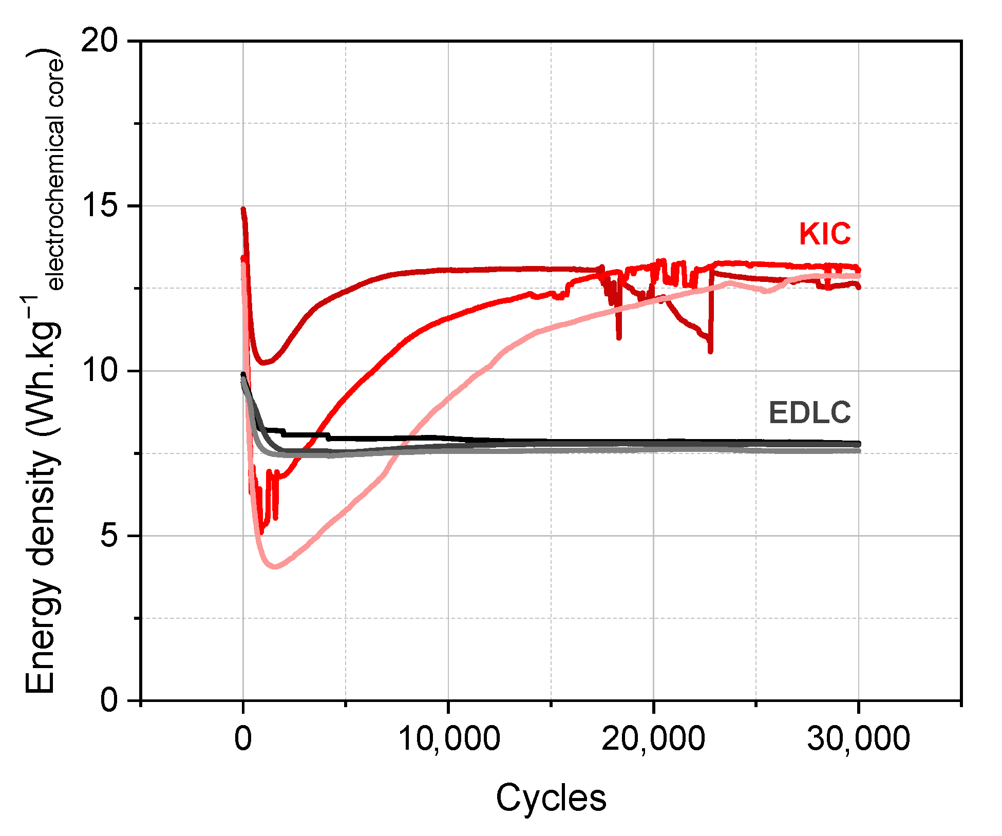
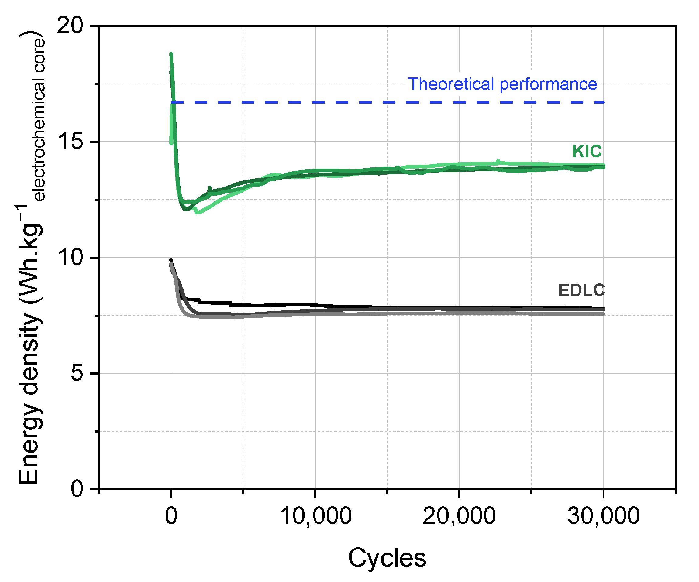
−2 (5C, with C being the capacity of the cell) at room temperature. The performance of the KIC cells that undergo this initial formation protocol, and those of the conventional EDLC, are presented in Figure 1 for a batch of three cells. A flow chart of cycling tests is presented in Figure S3. The energy densities are expressed per kilo of electrochemical core, the detailed description of which is given in the Supplementary Data.
Cycling performance of hybrid cells are characterized by a non-monotonous profile, with discharged capacities, which decrease drastically then increase in a few thousand cycles, as well as the non-reproducibility of the results between the identical cells. This initial formation protocol therefore allows obtaining energy densities higher than conventional supercapacitors; however, the performances are non-reproducible and unstable.
To improve the performance, a comparison with known systems such as lithium technologies has been made. In the case of the Li-ion battery, the formation protocol is well defined, with galvanostatic charge/discharge cycles at low current regime and high temperature [21]. The current and temperature therefore seem to be two important parameters for the formation protocol, and their influence has been studied in order to define an adequate protocol for KIC cells. Different configurations were tested with two current regimes, 0.82 and 0.08 mA·cm
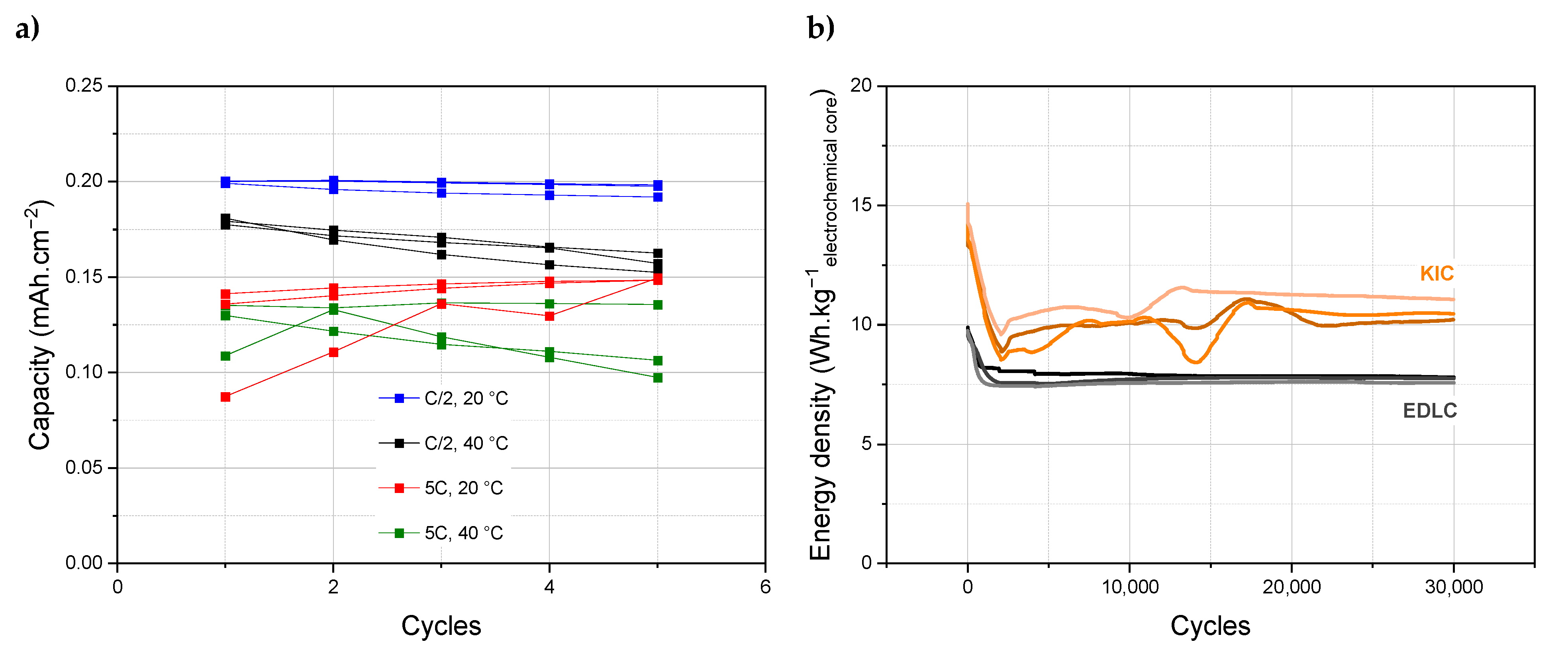
−2, respectively, 5C and C/2, and two temperatures, 20 and 40 °C. The capacities obtained during the five cycles of formation under different conditions are presented on Figure 2a.
Higher capacities are obtained for a current of 0.08 mA·cm−2 (blue and black curves) than of 0.82 mA·cm−2 (red and green curves). In addition, a formation protocol at room temperature (blue and red curves) allows for better performance than at a higher temperature (black and green curves). A lower current regime is therefore beneficial, unlike a higher temperature. Based on these results, an intermediate formation protocol has been developed which consists of five galvanostatic charge/discharge cycles at 0.08 mA·cm−2 (C/2) at room temperature. The performance of the cells that undergo this formation protocol are presented in Figure 2b for a batch of three cells. The intermediate formation protocol allows to obtain reproducible results; however, the energy densities obtained are lower and the stability of the system remains low.
At this stage of the development of a formation protocol for the KICs, a problem of cell swelling was highlighted. The generation of gases within the cells is a well-known issue, whether for supercapacitors or Li-ion batteries, and is generally related to the decomposition of the electrolyte. In the case of the non-aqueous potassium-ion hybrid supercapacitor studied, it is therefore necessary to know the stability window of the electrolyte used, and more precisely, of the solvent, acetonitrile.

3.2. Hypothesis—Electrochemical Stability Window of Acetonitrile

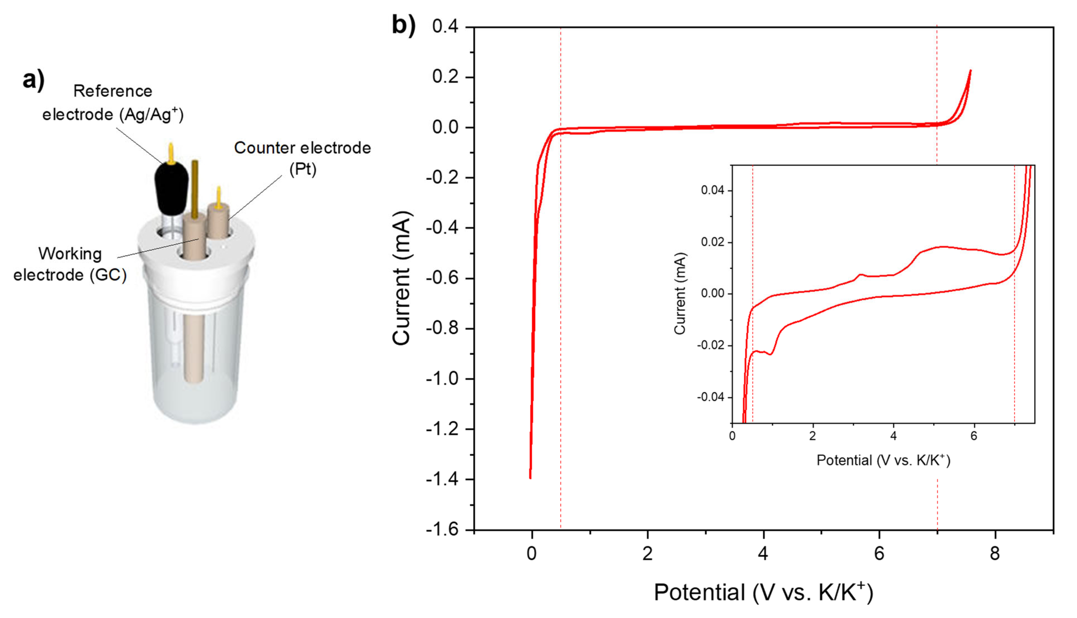
Figure 3 shows the electrochemical stability window of acetonitrile measured with a three-electrode set-up, with glassy-carbon as the working, Ag/Ag+ as the reference, and platinum as the counter electrode. The results are presented vs. K/K+ in order to be placed in the case of our study.
The three-electrode set-up seems to indicate that the lower limit of the electrochemical stability is at 0.5 V vs. K/K+, although a small reduction current is observed at 1 V vs. K/K+.
In this study, the potassium-ion hybrid supercapacitor works over the voltage range of 0.5–3.5 V. However, the potentials of each electrode vs. K/K+ are not known. While waiting to develop a reference electrode adapted to the KIC system studied, a hypothesis has been put forward to explain the generation of gas and continue the study. Studies have been able to show the compatibility of KPF6 salt with graphite electrodes [25] and acetonitrile [26]. The hypothesis is therefore related to the negative graphite electrode and acetonitrile. Depending on the stage of intercalation reached, the negative electrode of the KIC system could operate outside the electrochemical stability window of acetonitrile, i.e., below 0.5 V vs. K/K+. A schematic representation of the charge profile of the graphite electrode in the KIC system is therefore presented in Figure S4a to illustrate this instability.
As can be seen, a potential at the negative electrode lower than expected can quickly lead to the reduction of the solvent. Consequently, the instability of acetonitrile was questioned over the operation voltage range of the system when the swelling phenomenon was first observed. The study therefore focused on the high voltage phenomena, i.e., low negative electrode potential, as framed in Figure S4b on the charge/discharge profile of a KIC cell. However, as explained previously, the system is sized to reach a dilute intercalation stage to avoid volume expansion. The swelling phenomenon could therefore be caused by another phenomenon.

3.3. Identification of Voltage Ranges Responsible for Gas Production

To determine the instability voltage and understand the swelling of cells, constant voltage (CV) tests were carried out. CV is a well-known method for evaluating the aging of electrochemical systems, especially supercapacitors [27]. These tests consist of charging KIC cells at a constant current (0.08 mA·cm−2 corresponding to C/2 current regime) until various cut-off voltages, and then applying this voltage to the cells during 24 h. After that, the KIC cells are discharged at a constant current (0.08 mA·cm−2) down to 0.5 V. The charging cut-off voltage of the KIC varies from 3.0 to 3.7 V. A flow chart of constant voltage tests is presented in Figure S5. To ensure the reproducibility of the results, tests were carried out on a batch of three cells.
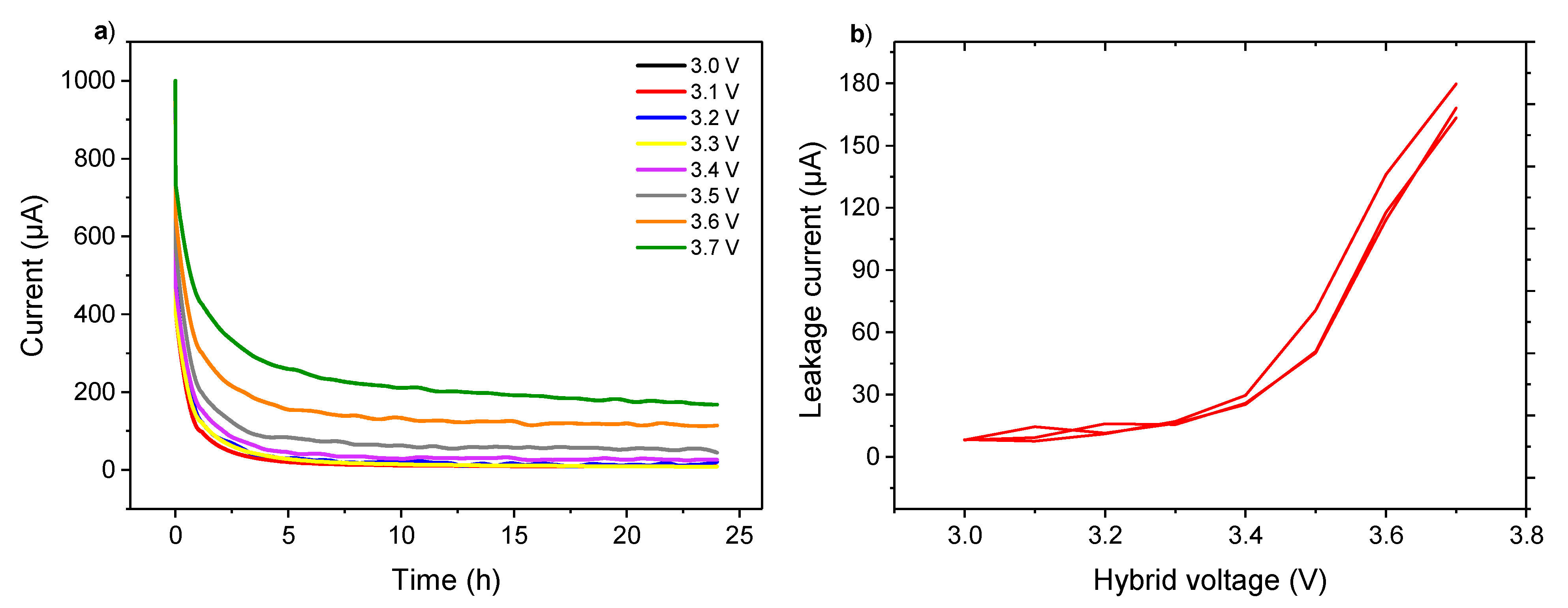
Figure 4a shows the currents of the KIC cells recorded at the constant-voltage steps. The residual current after 24 h at constant voltage, named the leakage current [28], was determined to evaluate its evolution with the applied voltage, as can be seen in Figure 4b. For the readability of the figure, Figure 4a presents the curves for a single cell while Figure 4b shows the results obtained for the batch of three cells.
At the beginning of the constant voltage step, a rapid decrease of the current was observed. Then, a stabilization occurred after approximatively 8 h. Two distinct behaviors were observed on the leakage current curve. First, low and stable values were measured between 3.0 and 3.4 V. Then, a significant increase was observed from 3.5 V.
The profiles of the leakage current during the CV step have been already observed in the case of the supercapacitors. As detailed in [29], this can be explained by the double-layer structure at the capacitor-type electrode, composed of a diffusion layer and a compact layer. Initially, the ions of the bulk flow to the diffusion layer result in a drastic decay of current. Then, the ions of the diffusion layer are pushed to the compact layer until the structure of the electrical double-layer is ordered, reaching equilibrium. Regarding the residual leakage current, the low-leakage current values during the first tests (Figure 4b) could reflect a range of stability for the KIC system that would be interesting to study. Indeed, these results suggest, as with [30], that the introduction of a constant voltage step within the formation protocol of the system could be beneficial. The impact of a CV step during formation on the cycling performance of the KIC system have been investigated and will be discussed later. As for the results at a higher voltage, the leakage current increases dramatically between 3.5 and 3.7 V. This window is beyond the voltage range of the KIC system operation, which accentuates the aging phenomena [31]. This increase can be related to the instability of acetonitrile. To obtain a higher cell voltage, the potential of the negative electrode must go down, and therefore potentially enter the instability window of acetonitrile, as illustrated in Figure S3a. The decomposition of the electrolyte therefore explains the high leakage currents observed, as described in the case of the LICs [30].
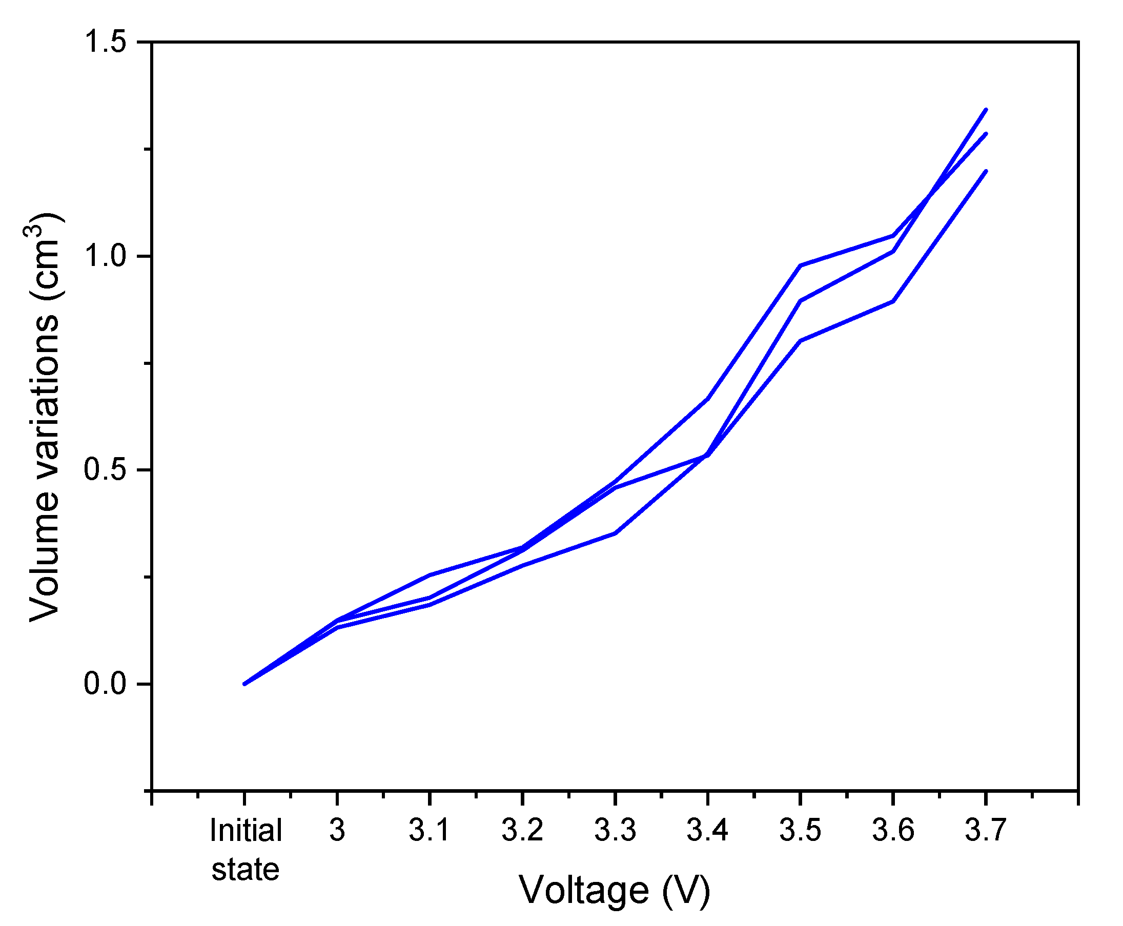
In parallel of the constant voltage tests, volume measurements using Archimedes’ principle were conducted. Figure 5 shows the volume variations of the cells as a function of the applied voltage. The initial value corresponds to the volume of the cells before any test. Then, the measurements are realized at a discharged state after each step of the CV tests on the voltage window from 3.0 to 3.7 V.
The general trend of the curve is a gradual increase in the cell volume, and this seems to intensify at a high voltage. Regardless of the cell voltage, the reactions that take place within the cells result in the generation of gases, causing the cell swelling.
Based on these results, the swelling of the cells has its origin in two phenomena. The first is related to the formation of the solid electrolyte interphase (SEI). This phenomenon is well studied in the case of Li-ion batteries [32] and starts to be referenced for K-ion batteries, but only in the case of carbonate solvents [33]. The negative electrode of the KIC system studied here is a battery-type one, so it is assumed that it undergoes a similar reaction. A comparison with symmetrical supercapacitors could isolate this contribution. Moreover, the SEI formation is due to the electrochemical reduction of the electrolyte solvents and reductive gases such as H2 dominate the gases released from the graphite anode. The composition of the gas generated within the cells would confirm this hypothesis. The second phenomenon is the decomposition of the electrolyte due to the extension of the operating voltage range up to 3.5 V, and therefore the operation of one or more electrodes of the system outside the stability window of the electrolyte. The SEI is therefore no longer sufficient to avoid the decomposition of the electrolyte at the negative electrode, or parasitic reactions take place at the positive electrode. The hypothesis put forward at the beginning of the swelling study must therefore be confirmed. It is then necessary to know the potential of each electrode, which requires the presence of a reference electrode in the system. The results in the three-electrode set-up are presented as well as additional tests in order to justify the phenomena described.

3.4. Hypotheses Evaluation

First, the hypothesis on the degradation of the electrolyte at a high cell voltage was evaluated. In order to do that, it is necessary to know the potential of the negative electrode to see if it drops below 0.5 V vs. K/K
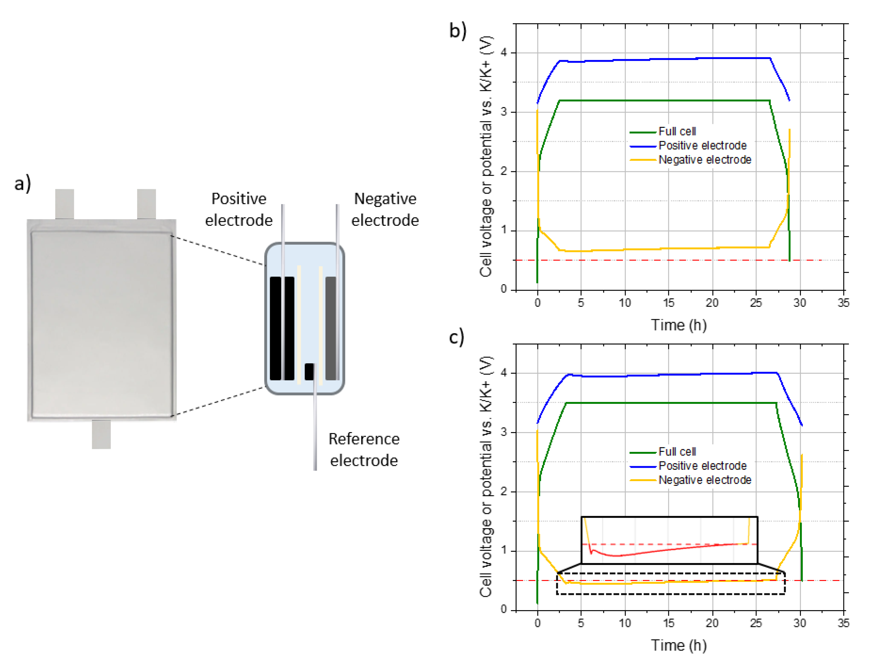
+. The three-electrode set-up with an additional reference electrode were then assembled, as shown schematically in Figure 6a. Considering the previous results, tests with this set-up were carried out for a voltage chosen in each of the following windows: 3.0–3.4 V and 3.5–3.7 V. Figure 6 shows the cell voltage and potentials vs. K/K+ of the positive and negative electrodes for the constant voltage tests, described previously, at 3.2 V (Figure 6b) and 3.5 V (Figure 6c). Each test was carried out on a batch of three cells in order to ensure the reproducibility of the results.
A rapid increase of cell voltage is observed between 0.5 and 2.2 V, followed by a neat change of slope for the two tests presented. The same behavior is observed for the potential of the negative electrode, while the potential of the AC positive electrode has a triangular profile highly characteristic of a purely capacitive behavior. For the test with a CV step at 3.2 V, the potential of the negative electrode drops to 0.66 V, whereas it decreases to 0.45 V for a CV step at 3.5 V. In addition, it can be seen that the potentials of both electrodes increase slightly during the constant voltage part. This phenomenon is still under study but is compatible with a reduction of the electrolyte at the graphite electrode.
These results show that the potential of the graphite electrode is lower with a CV step at 3.5 V, which could bring it below the stability limit of the acetonitrile (~0.5 V vs. K/K+) and explain the leakage current. If so, it can be seen from the enlargement of Figure 6c that the negative electrode spends a lot of time below this limit during the CV. This could explain the important volume increase due to significant gas generation.
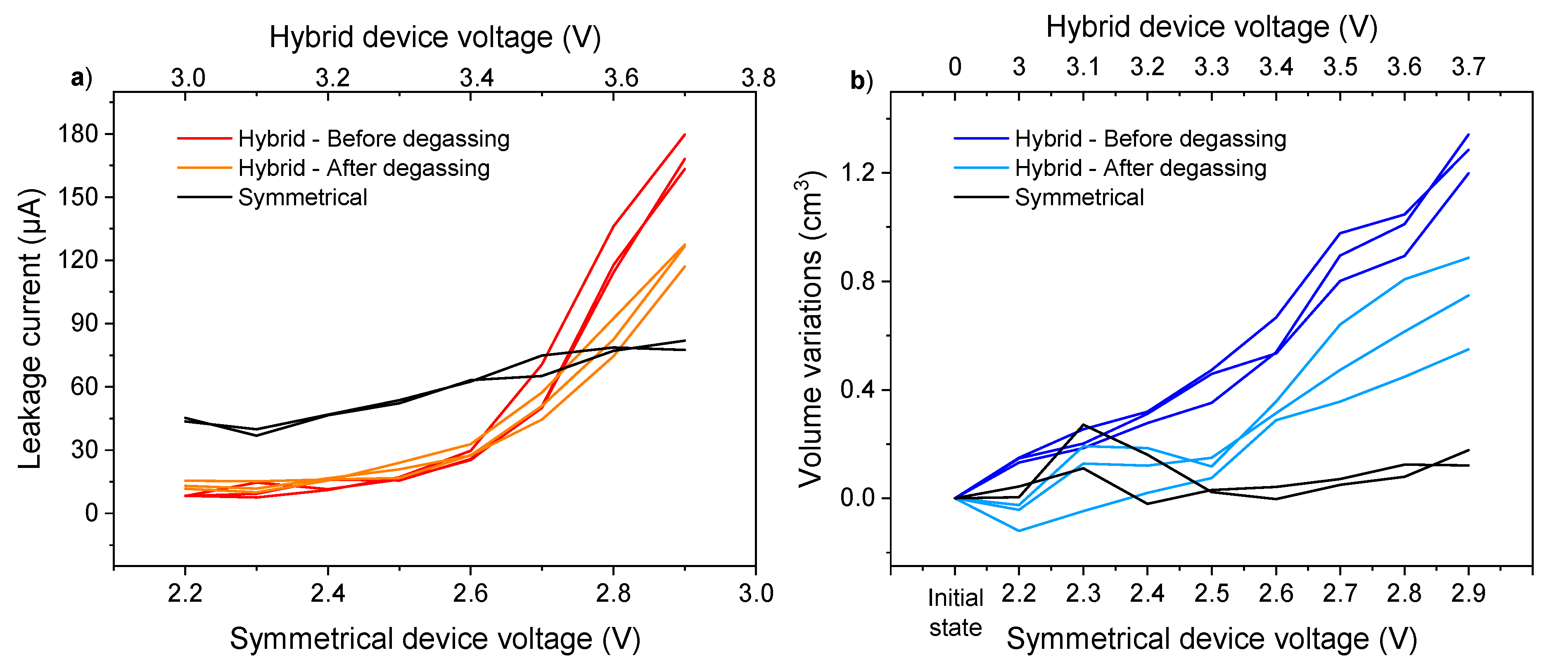
The origin of the phenomena observed at high voltage is now well defined. Although less important, the gas generation on the 3.0–3.4 V window still needs an explanation. For this purpose, we performed a degassing of the cells in order to know if this gas is linked to the passivation of the electrodes during the first use of the cells. Constant voltage tests as well as the volume measurements were performed again. Volume variations within cells and the evolution of the leakage current are shown in Figure 7 for the three hybrid cells.
In addition, a comparison between the symmetrical and hybrid device was carried out to decorrelate the phenomena taking place at the negative electrode and at the positive electrode. Each electrode can have a passivation layer [34], SEI at the negative side, and CEI at the positive side, giving rise to the generation of gas. Comparing the evolution of the cell volume in the symmetrical and hybrid configurations would therefore make it possible to identify at which electrode the degradation reactions take place. Symmetrical cells with two activated carbon electrodes were then assembled. To take into consideration the same degradation reactions, the same electrolyte is employed for both the hybrid and symmetrical devices. The operating voltage range of a KIC is up to 3.5 V, and the study was performed for voltages between 3.0 and 3.7 V. To keep the same logic and knowing that the operating voltage range of the EDLC studied is up to 2.7 V, constant voltage tests and volume measurements were performed on voltage ranges from 2.2 to 2.9 V for the symmetrical device. The evolutions of the leakage current and the volume variations of the cells with the applied voltage are shown on Figure 7 for a batch of two symmetrical cells.
The evolution of the leakage current and volume variations after the degassing of the hybrid cells have a flat profile up to 3.4 V. An increase, which follows the same trend as in the hybrid cells before degassing, is then observed. As for the symmetrical cells, apart from large leakage current values outside the operating range of the KIC cells, the leakage currents are greater in the symmetrical configuration from the first test. However, no significant variation is observed despite an increasing trend. In terms of volume variation, no change in volume of the symmetrical cells was observed over the voltage range studied.
For the hybrid cells, the same trends are observed before and after degassing in terms of the leakage current. However, the initial volume increase after the first tests was no longer observed after degassing. This can confirm that this was related to the formation of the KIC cells when they were first used. More precisely, the gas formed can come from the formation of the solid electrolyte interphase (SEI) at the negative electrode. In addition, the fact that no significant volume variation is observed after the first use of the symmetrical cells tends to confirm this hypothesis. The results after the test at 3.5 V show the same increasing trend before and after degassing, so another phenomenon than the formation of the cells is involved, as detailed previously with tests in the three-electrode set-up. On the other hand, the large values of the leakage current in the symmetrical configuration can be explained by the analysis of the storage mechanism of the electric double-layer capacitors (EDLC). As explained earlier, when an EDLC is charged, an electrical double-layer is formed to store energy. However, electrons can move inside this layer via redox reactions on the surface of the electrodes. The effect of these reactions is a high leakage current, which is minimized in the hybrid configuration by replacing the negative electrode. The standard leakage current values for supercapacitors are generally lower. This must be due to the material used and could be minimized by using material that has undergone other chemical or thermal treatments [35]. However, the same material is used throughout the study and therefore has no influence on the comparative observations made.
In a symmetrical configuration, this large leakage current is not accompanied by swelling, since no variation in volume is observed. A notable difference therefore exists between the behavior of the hybrid and symmetrical systems at a high voltage. Despite an increasing trend, the leakage current values of the symmetrical cells remain lower than those of the hybrid cells. This is explained by a difference in the working potential of the negative electrode, depending on the configuration. In the case of the KIC system, the negative graphite electrode drops to potentials below 0.5 V vs. K/K+ (Figure 6c). The reduction of acetonitrile gives rise to the generation of gas, explaining the high leakage currents and volume variations. For a symmetrical system working on a voltage window of 2.7 V, the negative electrode does not drop below 1.5 V vs. K/K+ (i.e., 1.6 V vs. Li/Li+), as detailed in [36] and confirmed in this study with a three-electrode set-up (Figure S6).
The swelling phenomenon therefore seems to be a problem specific to the hybrid configuration. These results are consistent with this study. The development of a formation protocol adapted to the hybrid system studied is necessary, whereas this is not the case for a symmetrical system. In addition, the hypothesis, according to which the phenomena observed during the first use are linked to the passivation of the negative electrode of the system, is confirmed by these additional tests. However, surface analyses to study the SEI layer and its evolution are still necessary.

3.5. Gas Analysis

By volume measurements, the extent of gassing is known, as well as the voltage ranges over which it occurs. To understand the origin of the swelling phenomenon, the constituents of the gas evolved need now to be identified. This is why the analysis by gas chromatography coupled with mass spectrometry were realized. Gas can be extracted from cells postmortem through the use of a syringe. Then, the resulting gas can be injected into a bag filled with argon, connected to the gas chromatography mass spectrometer for analysis to ascertain the species present. The cells used for this analysis did all constant voltage tests and started cycling at 16 mA·cm2 (100C/100D) during 20,000 cycles for the aging tests. The chromatogram obtained by making the ratio of our signal to that of argon is shown on Figure S7.
Two contributions can be observed. The first one at 0.44 min is associated to hydrogen. Then, the second contribution is due to a pollution of the equipment by the ambient air. Thus, hydrogen is the only gas present in our cells, as it has been observed in LICs [37].
It is important to note that all system components must be properly dried to minimize the swelling phenomenon. In fact, the quantity of gas generated is all the greater in the presence of water, since hydrogen can be produced by its reduction [19]. The importance of the presence of water in the electrolyte could be observed. This is why Karl-Fischer analyses were carried out before the tests to rule out the presence of water (<2 ppm in the electrolyte) as a phenomenon responsible for the swelling.
The origin of hydrogen therefore comes from another reaction. As detailed in [38], the decomposition of acetonitrile is likely to begin with the cleavage of a C-H bond because the C-N bond has a higher dissociation energy. H+ atoms are therefore assumed to be formed through the reaction (4). However, the deprotonization could also be promoted by the oxidation of the salt component, as it is the case in conventional supercapacitors and described in [39,40].
CH 3 CN     H + +   CH 2 CN  
As previously explained, hydrogen is the dominant gas produced during the electrochemical decomposition of electrolyte solvents resulting in the SEI formation in Li-ion batteries. These gas analyses confirm that this is also the case for the KIC system studied. In addition, the results presented above show that the lower limit of the stability window of acetonitrile is 0.5 V vs. K/K+. Below this limit, the decomposition reaction of acetonitrile takes place. To prevent additional hydrogen production, it is therefore essential that the negative electrode does not drop down to this potential. However, it has been proven in a three-electrode set-up that this is not the case when the system voltage rises up to 3.5 V. This explains the significant production of gas associated with high leakage currents from this voltage.

3.6. Definition of a New Formation Protocol—Performance Improvements

As explained previously, the performance of KIC cells could be improved by decreasing the current regime applied during the formation protocol. The results obtained are reproducible, but the energy densities are lower and the stability is still a problem. After the observation of a swelling of the cells, the study of this phenomenon made it possible to identify a possible origin. Additionally, this highlighted the need to further optimize the formation protocol to avoid gas generation and ensure long-term system operation.
During the swelling study, low leakage currents were observed over a given voltage range (Figure 4b). As mentioned previously, this could reflect a range of stability for the KIC system that would be interesting to study. Indeed, these results suggest, as in [30], that the introduction of a constant voltage step within the formation protocol of the system could be beneficial. Moreover, the results in the three-electrode set-up suggest that the potential of the negative electrode operates outside the electrochemical stability window of the electrolyte for a voltage of 3.5 V, whereas this is not the case for a voltage of 3.2 V.
Adding a constant voltage step at 3.2 V could help minimize gas generation by allowing the system to slowly develop an SEI while staying in the stability window of acetonitrile. The question is whether this SEI would be effective when operating over the full voltage range 0.5–3.5 V of the system. Additional tests in a three-electrode set-up were therefore carried out. Figure S8 shows the cell voltage and potentials vs. K/K+ of the positive and negative electrodes for constant voltage test at 3.2 V (charge at 0.08 mA·cm−2 up to 3.2 V—24-h constant voltage step—discharge at 0.08 mA·cm−2 up to 0.5 V), followed by a galvanostatic charge/discharge at 0.08 mA·cm−2 mA (C/2). Tests were carried out on a batch of three cells in order to ensure the reproducibility of the results.
As detailed on Figure 6, a rapid increase of cell voltage is observed between 0.5 and 2.2 V, followed by a neat change of slope. The potential of the negative electrode follows the same pattern, while the potential of the AC positive electrode has a triangular profile highly characteristic of a purely capacitive behavior. The same behaviors are observed during the following galvanostatic charge/discharge cycle. The potential of the negative electrode drops to 0.66 V during the CV step at 3.2 V and to 0.57 V during the cycle which follows.
The potential of each electrode, and in particular of the negative, is therefore within the stability window of acetonitrile during the constant voltage step, as well as during the cycle which follows. It can therefore be deduced that there is no decomposition of the electrolyte and therefore no gas.
Based on these results, a final formation protocol has been developed which consists of a charge at 0.08 mA·cm−2 up to 3.2 V, a 24 h constant voltage step at 3.2 V, and a discharge at 0.08 mA·cm
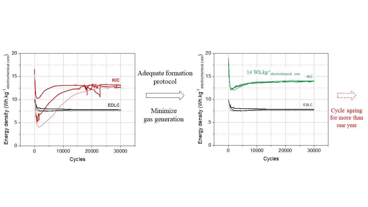
−2 up to 0.5 V at room temperature. A degassing of the cell is then carried out before cycling to evacuate the gases generated during the formation of the SEI. The performance of the cells that undergo this formation protocol are presented in Figure 8 for a batch of three cells.
A significant drop in performance is observed at the beginning of cycling from approximately 19 to 12 Wh·kgelectrochemical core−1. This is followed by a rise and then a stabilization of the performance between 12.7 and 14 Wh·kgelectrochemical core−1. In addition, the results are reproducible on the batch of three cells.
The initial drop in performance is a behavior that has also been observed in the case of symmetrical supercapacitors [9]. Regarding the rise, it is a phenomenon specific to M-ion hybrid supercapacitors (MICs) related to the SEI formation and a cycling-induced capacity gain, as detailed in [2] for carbon-supported nanomaterials. After the stabilization of the performance, it can be concluded that the final formation protocol developed allows stable and reproducible results with high energy densities of up to 14 Wh·kgelectrochemical core−1.

4. Conclusions and Perspectives

In this work, the objective was to develop an adequate formation protocol for a non-aqueous potassium-ion hybrid supercapacitor (KIC). The interest of this system is to combine the high power and cyclability of conventional supercapacitors with a higher energy density by replacing one of the activated carbon electrodes. However, this hybrid configuration also brings its share of disadvantages. Among them, a non-monotonous cycle aging with discharged capacities, which decrease drastically then increase in a few thousand cycles, as well as the non-reproducibility of the results for identical cells were observed with the system initially developed. These results show the importance of developing a formation protocol adapted to this KIC technology. For this purpose, two research paths have been chosen. First, the comparison with known systems, such as lithium-ion batteries, made it possible to identify key parameters of the formation protocol. Secondly, the study of cell swelling, a well-known problem, whether for supercapacitors or Li-ion batteries, has been realized here in the case of KICs.
By analyzing the formation protocol of lithium-ion batteries, two parameters have been identified as essential: the current regime and the temperature. In the case of KICs, it has been proven that a lower current regime is beneficial, unlike a higher temperature. Based on these results, an intermediate formation protocol has been developed. The latter allows to obtain reproducible results; however, the energy densities obtained are lower than those obtained with the initial formation protocol and the stability of the system remains low.
From there, a second research path was followed, since cell swelling was observed. The study of this phenomenon was therefore investigated using constant voltage tests and volume measurements. It has been proven that the swelling of cells is caused by hydrogen production originating from two distinct phenomena. On the one hand, the formation of the SEI layer at the battery-type negative electrode during the first use of the system, and, on the other hand, the decomposition of the electrolyte solvent due to the extension of the operating voltage range up to 3.5 V identified with a three-electrode set-up. Additional tests have demonstrated that swelling is a problem specific to the hybrid configuration and that the first contribution can be eliminated by degassing.
The presence of gas in a cell can have important consequences, with the production of highly flammable gases that can onset thermal runaway, as mentioned in [19]. In addition to the safety issues attributed to gas evolution, it can also heavily impact cell performance. This could be responsible for the unstable performance observed for the moment during the operation of the KIC system presented. An optimization of the formation protocol was therefore still necessary to avoid the generation of gas and ensure the long-term operation of the system.
The low leakage currents observed during the swelling study, as well as the tests carried out with the three-electrode set-up, suggest that adding a constant voltage step during the formation protocol could help minimize gas generation. This step made at the correct voltage has proven to allow the system to operate within the stability window of acetonitrile during formation, but also during cycling. From these results, a final formation protocol has been developed. Cells that undergo this protocol show stable and reproducible results with high energy densities of up to 14 Wh·kg−1.
To conclude, the development of a formation protocol adapted to the non-aqueous potassium-ion hybrid supercapacitor presented has led to reproducible results with higher energy densities than conventional supercapacitors. In addition, the pursuit of cycling made it possible to show an excellent stability over more than 500,000 cycles at 100C/100D (tcharge/discharge = 30 s) with C as the cell capacity, as presented in Figure 9.
These results at the pouch cell level are highly remarkable and hardly observed in the case of other MICs. The analysis of the SEI layer and its evolution through different characterization techniques (XPS, SEM, TEM) will therefore be the next step to understand how the formation protocol influences the performance of the KIC system.

5. Patents

The development of this adequate formation protocol for the KIC technology studied has been patented (FR2109574).

Supplementary Materials

The following supporting information can be downloaded at: https://www.mdpi.com/article/10.3390/batteries8100135/s1. Figure S1: Pouch cell used for the tests; Figure S2: Experimental set-up carried out for volume measurements using Archimedes’ principle; Definition of the electrochemical core; Figure S3: Flow chart of cycling tests conducted in this paper; Figure S4: (a) Schematic representation of potential profile vs. specific capacity of the negative electrode, and b) charge/discharge galvanostatic profile at 16 mA·cm−2 (100C rate) of graphite/AC hybrid supercapacitor in pouch cell configuration using 0.8 mol·L−1 KPF6 AN at room temperature and ambient pressure; Figure S5: Flow chart of constant voltage tests conducted in this paper; Figure S6: (a) Schematic representation of the three-electrode step-up for symmetrical configuration, and (b) charge/discharge profiles at +/− 0.08 mA·cm−2 of an AC/AC supercapacitor in three-electrode cell configuration using 0.8 mol·L−1 KPF6 AN. The cell voltage (green) is measured while the reference electrode is used to calculate the potentials of the positive (blue) and negative (yellow) electrodes; Figure S7: Chromatogram of gas extracted from aged graphite/AC hybrid cells using 0.8 mol·L−1 KPF6 AN; Figure S8: (a) Cell voltage and electrode potentials profiles of graphite/AC hybrid supercapacitors in three-electrode set-up using 0.8 mol·L−1 KPF6 AN with a charge/discharge at +/− 0.08 mA·cm−2 and a 24-h constant voltage step at 3.2 V, followed by a galvanostatic charge/discharge cycle at +/− 0.08 mA·cm−2.

Author Contributions

Formal analysis, M.-E.Y.; investigation, M.-E.Y.; supervision, B.C., E.M., F.P. and P.A.; visualization, M.-E.Y.; writing—original draft, M.-E.Y.; writing—review and editing, M.-E.Y., B.C., E.M., F.P. and P.A. All authors have read and agreed to the published version of the manuscript.

Funding

This work is supported by a joint doctoral fellowship from the French Atomic Energy and Alternative Energy Agency (CEA) and the Direction Générale de l’Armement (DGA).

Institutional Review Board Statement

Not applicable.

Informed Consent Statement

Not applicable.

Data Availability Statement

Not applicable.

Acknowledgments

The authors would like to thank Léo Merchat and Claire Deilhes for the electrodes preparation and the GC-MS measurements, respectively.

Conflicts of Interest

The authors declare no conflict of interest.

References

  1. Lin, Z.; Goikolea, E.; Balducci, A.; Naoi, K.; Taberna, P.-L.; Salanne, M.; Yushin, G.N.; Simon, P. Materials for supercapacitors: When Li-ion battery power is not enough. Mater. Today 2018, 21, 419–436. [Google Scholar] [CrossRef]
  2. Ding, J.; Hu, W.; Paek, E.; Mitlin, D. Review of Hybrid Ion Capacitors: From Aqueous to Lithium to Sodium. Chem. Rev. 2018, 118, 6457–6498. [Google Scholar] [CrossRef] [PubMed]
  3. Muzaffar, A.; Ahamed, M.B.; Deshmukh, K.; Thirumalai, J. A review on recent advances in hybrid supercapacitors: Design, fabrication and applications. Renew. Sustain. Energy Rev. 2019, 101, 123–145. [Google Scholar] [CrossRef]
  4. Yuan, J.; Hu, X.; Liu, Y.; Zhong, G.; Yu, B.; Wen, Z. Recent progress in sodium/potassium hybrid capacitors. Chem. Commun. 2020, 56, 13933–13949. [Google Scholar] [CrossRef]
  5. Anoopkumar, V.; Bibin, J.; Mercy, T.D. Potassium-Ion Batteries: Key to Future Large-Scale Energy Storage? ACS Appl. Energy Mater. 2020, 3, 9478–9492. [Google Scholar] [CrossRef]
  6. Rajagopalan, R.; Tang, Y.; Ji, X.; Jia, C.; Wang, H. Advancements and Challenges in Potassium Ion Batteries: A Comprehensive Review. Adv. Funct. Mater. 2020, 30, 1909486. [Google Scholar] [CrossRef]
  7. Liu, M.; Chang, L.; Le, Z.; Jiang, J.; Li, J.; Wang, H.; Zhao, C.; Xu, T.; Nie, P.; Wang, L. Emerging Potassium-ion Hybrid Capacitors. ChemSusChem 2020, 13, 5837–5862. [Google Scholar] [CrossRef]
  8. Zhang, W.; Liu, Y.; Guo, Z. Approaching high-performance potassium-ion batteries via advanced design strategies and engineering. Sci. Adv. 2019, 5, eaav7412. [Google Scholar] [CrossRef]
  9. Le Comte, A.; Reynier, Y.; Vincens, C.; Leys, C.; Azaïs, P. First prototypes of hybrid potassium-ion capacitor (KIC): An innovative, cost-effective energy storage technology for transportation applications. J. Power Sources 2017, 363, 34–43. [Google Scholar] [CrossRef]
  10. Xu, J.; Dou, Y.; Wei, Z.; Ma, J.; Deng, Y.; Li, Y.; Liu, H.; Dou, S. Recent Progress in Graphite Intercalation Compounds for Rechargeable Metal (Li, Na, K, Al)-Ion Batteries. Adv. Sci. 2017, 4, 1700146. [Google Scholar] [CrossRef] [Green Version]
  11. Miller, J.R.; Butler, S. Measurement of gas pressure in packaged electric double layer capacitors. J. Power Sources 2021, 509, 230366. [Google Scholar] [CrossRef]
  12. Liu, Y.; Réty, B.; Matei Ghimbeu, C.; Soucaze-Guillous, B.; Taberna, P.-L.; Simon, P. Understanding ageing mechanisms of porous carbons in non-aqueous electrolytes for supercapacitors applications. J. Power Sources 2019, 434, 226734. [Google Scholar] [CrossRef]
  13. Kötz, R.; Hahn, M.; Ruch, P.; Gallay, R. Comparison of pressure evolution in supercapacitor devices using different aprotic solvents. Electrochem. Commun. 2008, 10, 359–362. [Google Scholar] [CrossRef]
  14. Galushkin, N.E.; Yazvinskaya, N.N.; Galushkin, D.N. Mechanism of Gases Generation during Lithium-Ion Batteries Cycling. J. Electrochem. Soc. 2019, 166, A897. [Google Scholar] [CrossRef]
  15. Phadke, S.; Amara, S.; Anouti, M. Gas Evolution in Activated-Carbon-Based Supercapacitors with Protic Deep Eutectic Solvent as Electrolyte. ChemPhysChem 2017, 18, 2364–2373. [Google Scholar] [CrossRef]
  16. Liu, Y.; Soucaze-Guillous, B.; Taberna, P.-L.; Simon, P. Understanding of carbon-based supercapacitors ageing mechanisms by electrochemical and analytical methods. J. Power Sources 2017, 366, 123–130. [Google Scholar] [CrossRef]
  17. Azaïs, P.; Duclaux, L.; Florian, P.; Massiot, D.; Lillo-Rodenas, M.-A.; Linares-Solano, A.; Peres, J.-P.; Jehoulet, C.; Béguin, F. Causes of supercapacitors ageing in organic electrolyte. J. Power Sources 2007, 171, 1046–1053. [Google Scholar] [CrossRef]
  18. Ellis, L.D.; Allen, J.P.; Thompson, L.M.; Harlow, J.E.; Stone, W.J.; Hill, I.G.; Dahn, J.R. Quantifying, Understanding and Evaluating the Effects of Gas Consumption in Lithium-Ion Cells. J. Electrochem. Soc. 2017, 164, A3518–A3528. [Google Scholar] [CrossRef]
  19. Rowden, B.; Garcia-Araez, N. A review of gas evolution in lithium ion batteries. Energy Rep. 2020, 6, 10–18. [Google Scholar] [CrossRef]
  20. El Ghossein, N. Étude et Modélisation du Fonctionnement et du Vieillissement des “Lithium-Ion Capacitors” (LiC). Ph.D. Thesis, Université de Lyon, Lyon, France, 2018. Available online: https://tel.archives-ouvertes.fr/tel-02275806 (accessed on 26 October 2021).
  21. Wood, D.L.; Li, J.; An, S.J. Formation Challenges of Lithium-Ion Battery Manufacturing. Joule 2019, 3, 2884–2888. [Google Scholar] [CrossRef]
  22. Pell, W.; Conway, B. Peculiarities and requirements of asymmetric capacitor devices based on combination of capacitor and battery-type electrodes. J. Power Sources 2004, 136, 334–345. [Google Scholar] [CrossRef]
  23. Li, Y.; Lu, Y.; Adelhelm, P.; Titirici, M.-M.; Hu, Y.-S. Intercalation chemistry of graphite: Alkali metal ions and beyond. Chem. Soc. Rev. 2019, 48, 4655–4687. [Google Scholar] [CrossRef] [PubMed]
  24. Aiken, C.; Xia, J.; Wang, D.; Stevens, D.; Trussler, S.; Dahn, J. An Apparatus for the Study of In Situ Gas Evolution in Li-Ion Pouch Cells. J. Electrochem. Soc. 2014, 161, A1548–A1554. [Google Scholar] [CrossRef]
  25. Gu, M.; Fan, L.; Zhou, J.; Rao, A.M.; Lu, B. Regulating Solvent Molecule Coordination with KPF 6 for Superstable Graphite Potassium Anodes. ACS Nano 2021, 15, 9167–9175. [Google Scholar] [CrossRef] [PubMed]
  26. Amara, S.; Toulc’Hoat, J.; Timperman, L.; Biller, A.; Galiano, H.; Marcel, C.; Ledigabel, M.; Anouti, M. Comparative Study of Alkali-Cation-Based (Li+, Na+, K+) Electrolytes in Acetonitrile and Alkylcarbonates. ChemPhysChem 2019, 20, 581–594. [Google Scholar] [CrossRef]
  27. German, R.; Sari, A.; Venet, P.; Zitouni, Y.; Briat, O.; Vinassa, J.-M. Ageing law for supercapacitors floating ageing. In Proceedings of the 2014 IEEE 23rd International Symposium on Industrial Electronics (ISIE), Istanbul, Turkey, 1–4 June 2014. [Google Scholar] [CrossRef]
  28. Kurzweil, P.; Frenzel, B.; Gallay, R. Capacitance Characterization Methods and Ageing Behaviour of Supercapacitors. In Proceedings of the 15th International Seminar on Double Layer Capacitors, Deerfield Beach, FL, USA, 5–7 December 2015; p. 12. [Google Scholar]
  29. Ratajczak, P.; Jurewicz, K.; Béguin, F. Factors contributing to ageing of high voltage carbon/carbon supercapacitors in salt aqueous electrolyte. J. Appl. Electrochem. 2014, 44, 475–480. [Google Scholar] [CrossRef]
  30. Sun, X.; An, Y.; Geng, L.; Zhang, X.; Wang, K.; Yin, J.; Huo, Q.; Wei, T.; Zhang, X.; Ma, Y. Leakage current and self-discharge in lithium-ion capacitor. J. Electroanal. Chem. 2019, 850, 113386. [Google Scholar] [CrossRef]
  31. He, M.; Fic, K.; Frckowiak, E.; Novák, P.; Berg, E.J. Ageing phenomena in high-voltage aqueous supercapacitors investigated by in situ gas analysis. Energy Environ. Sci. 2016, 9, 623–633. [Google Scholar] [CrossRef]
  32. An, S.J.; Li, J.; Daniel, C.; Mohanty, D.; Nagpure, S.; Wood, D.L. The state of understanding of the lithium-ion-battery graphite solid electrolyte interphase (SEI) and its relationship to formation cycling. Carbon 2016, 105, 52–76. [Google Scholar] [CrossRef] [Green Version]
  33. Wang, H.; Zhai, D.; Kang, F. Solid electrolyte interphase (SEI) in potassium ion batteries. Energy Environ. Sci. 2020, 13, 4583–4608. [Google Scholar] [CrossRef]
  34. Edge, J.S.; O’Kane, S.; Prosser, R.; Kirkaldy, N.D.; Patel, A.N.; Hales, A.; Ghosh, A.; Ai, W.; Chen, J.; Yang, J.; et al. Lithium ion battery degradation: What you need to know. Phys. Chem. Chem. Phys. 2021, 23, 8200–8221. [Google Scholar] [CrossRef] [PubMed]
  35. Ike, I.S.; Sigalas, I.; Iyuke, S. Understanding performance limitation and suppression of leakage current or self-discharge in electrochemical capacitors: A review. Phys. Chem. Chem. Phys. 2015, 18, 661–680. [Google Scholar] [CrossRef] [PubMed]
  36. Naoi, K. ‘Nanohybrid Capacitor’: The Next Generation Electrochemical Capacitors. Fuel Cells 2010, 10, 825–833. [Google Scholar] [CrossRef]
  37. Iwama, E.; Ueda, T.; Ishihara, Y.; Ohshima, K.; Naoi, W.; Reid, M.; Naoi, K. High-voltage operation of Li4Ti5O12/AC hybrid supercapacitor cell in carbonate and sulfone electrolytes: Gas generation and its characterization. Electrochim. Acta 2019, 301, 312–318. [Google Scholar] [CrossRef]
  38. Moldoveanu, S.C. Chapter 14—Pyrolysis of Various Derivatives of Carboxylic Acids. In Pyrolysis of Organic Molecules, 2nd ed.; Moldoveanu, S.C., Ed.; Elsevier: Amsterdam, The Netherlands, 2019; pp. 635–696. ISBN 978-0-444-64000-0. [Google Scholar]
  39. Bittner, A.M.; Zhu, M.; Yang, Y.; Waibel, H.F.; Konuma, M.; Starke, U.; Weber, C.J. Ageing of electrochemical double layer capacitors. J. Power Sources 2012, 203, 262–273. [Google Scholar] [CrossRef]
  40. Zhu, M.; Weber, C.J.; Yang, Y.; Konuma, M.; Starke, U.; Kern, K.; Bittner, A.M. Chemical and electrochemical ageing of carbon materials used in supercapacitor electrodes. Carbon 2008, 46, 1829–1840. [Google Scholar] [CrossRef]
Figure 1. Long-term cycling of hybrid KIC in 0.8 mol L−1 KPF6 AN at a regime of 100C/100D between 0.5 and 3.5 V in pouch cell configuration after the initial formation protocol and long-term cycling of symmetrical EDLC in 0.8 mol·L−1 TEABF4 AN at a regime of 100C/100D between 0.5 and 2.7 V.
Batteries 08 00135 g001
Figure 2. (a) Capacities obtained during 5 cycles of formation at different current and temperature, (b) Long-term cycling of hybrid KIC in 0.8 mol L−1 KPF6 AN at a regime of 100C/100D between 0.5 and 3.5 V in pouch cell configuration after the “intermediate” formation protocol (5 cycles at C/2 and 20 °C), and long-term cycling of symmetrical EDLC in 0.8 mol·L−1 TEABF4 AN at a regime of 100C/100D between 0.5 and 2.7 V.
Batteries 08 00135 g002
Figure 3. (a) Three-electrode set-up used for measurement; (b) Electrochemical stability window of acetonitrile (WE = GC; RE = Ag/Ag+; CE = Pt) with a 1.0 mol·L−1 KPF6 salt.
Batteries 08 00135 g003
Figure 4. (a) Comparison of current evolution under various voltage from 3.0 to 3.7 V; (b) Ending leakage current evolution with the applied voltage of graphite/AC hybrid supercapacitors in pouch cell configuration using 0.8 mol·L−1 KPF6 AN at room temperature and ambient pressure.
Batteries 08 00135 g004
Figure 5. Volume variations of graphite/AC hybrid supercapacitors in 0.8 mol·L−1 KPF6 AN over the voltage range of 3.0 to 3.7 V measured using Archimedes’ principle at room temperature and ambient pressure.
Batteries 08 00135 g005
Figure 6. (a) Schematic representation of the three-electrode step-up, constant voltage test profiles of graphite/AC hybrid supercapacitors in three-electrode cell configuration using 0.8 mol·L−1 KPF6 AN with a charge/discharge at +/− 0.08 mA.cm−2, and a 24 h constant voltage step at (b) 3.2 V or (c) 3.5 V. The cell voltage (green) is measured while the reference electrode is used to calculate the potentials of the positive (blue) and negative (yellow) electrodes.
Batteries 08 00135 g006
Figure 7. Comparison of ending leakage current (a) and volume variation (b) evolutions in AC/AC symmetrical device and graphite/AC hybrid devices before and after degassing using 0.8 mol·L−1 KPF6 AN at room temperature and ambient pressure.
Batteries 08 00135 g007
Figure 8. Long-term cycling of hybrid KIC in 0.8 mol L−1 KPF6 AN at a regime of 100C/100D between 0.5 and 3.5 V in pouch cell configuration after the final formation protocol and long-term cycling of symmetrical EDLC in 0.8 mol·L−1 TEABF4 AN at a regime of 100C/100D between 0.5 and 2.7 V.
Batteries 08 00135 g008
Figure 9. Long-term cycling of hybrid KIC in 0.8 mol L−1 KPF6 AN at a regime of 100C/100D without any pause in pouch cell configuration.
Batteries 08 00135 g009
Publisher’s Note: MDPI stays neutral with regard to jurisdictional claims in published maps and institutional affiliations.

