Abstract
Zinc-ion batteries (ZIBs) have received attention as one type of multivalent-ion batteries due to their potential applications in large-scale energy storage systems. Here we report a prototype of rocking-chair ZIB system employing Zn2Mo6S8 (zinc Chevrel phase) as an anode operating at 0.35 V, and K0.02(H2O)0.22Zn2.94[Fe(CN)6]2 (rhombohedral zinc Prussian-blue analogue) as a cathode operating at 1.75 V (vs. Zn/Zn2+) in ZnSO4 aqueous electrolyte. This type of cell has a benefit due to its intrinsic zinc-dendrite-free nature. The cell is designed to be positive-limited with a capacity of 62.3 mAh g−1. The full-cell shows a reversible cycle with an average discharge cell voltage of ~1.40 V, demonstrating a successful rocking-chair zinc-ion battery system.
1. Introduction
Recently emerging technologies such as smart grids and renewable energy grids utilizing solar and wind power are placing urgent demands on the higher performance of batteries for large-scale stationary energy storage systems (ESSs) [1,2]. Thus far, lithium-ion batteries (LIBs) have been the most successful energy storage system, due to their high energy and power densities. However, there have been increasing concerns regarding safety [3], cost, and the uneven distribution of lithium resources, resulting in the vigorous development of post-LIB systems over the last few years, such as sodium-ion, potassium-ion [4], and multivalent-ion (Mg, Ca, and Zn)-based batteries [5].
Rechargeable zinc-ion batteries (ZIBs) have received attention as large-scale energy storage systems, and are expected to provide various advantages such as low toxicity and cost, abundance of the element, safety, and potential high energy density [6]. In recent years, many host compounds have been investigated for rechargeable electrochemical zinc-ion intercalation. Some inorganic examples would include various types of MnO2 (hollandite [7], birnessite [8] and todorokite [9]), Chevrel phase Mo6S8 [10,11,12], Prussian-blue analogues (A2Zn3[Fe(CN)6]2) [13,14], KxNiFe(CN)6 [15], KxCuFe(CN)6 [16]), ZnMn2O4 [17], ZnNixMnxCo2−2xO4 [18], Na3V2(PO4)3 [19], VS2- [20], VO2 [21], V2O5 [22], VO1.52(OH)0.77 [23], Mo2.5+yVO9+z [24], LiV3O8 [25], Zn2V2O7 [26], Zn0.25V2O5∙nH2O [27], Zn2(OH)VO4 [28], Na3V2(PO4)2F3 [29], Mn3O4 [30], Co3O4 [31], H2V3O8 [32], and Fe5V15O39(OH)9⋅9H2O [33], where zinc ions are reversibly intercalated into the structures in an aqueous electrolyte with ZnSO4, Zn(NO3)2, Zn(O2CCH3)2, or Zn(CF3SO3)2.
It should be pointed out that a pure, composite, or fabricated zinc-metal-based anode has been adopted for most of the previous studies. Zinc metal is well known to form a dendrite during the charging (deposition) process [34] (see also Figure S1)—similar to Li metal, which grows continually, piercing the separator and causing a short circuit, and will eventually lead to a loss in the efficiency and capacity of batteries. In particular, since ZIBs are candidates for ESSs that are expected to have a long cycle life (>10 years), preventing dendrite formation would be one of the most important requirements for commercialization of ZIBs. To prevent the zinc dendrite, investigations have been actively underway by developing zinc-based anode materials (e.g., carbon/zinc composites [35], CaCO3-coated zinc [36], hyper-dendritic zinc [37], or flowing zinc anode [38]), and by modifying electrolytes (e.g., organic electrolyte [15], adding additives [31,39], or high concentration [40]). Besides, aqueous zinc electrolytes lead to form byproducts at the zinc anode [16,41], causing another problem to solve in the form of the low Coulombic efficiency.
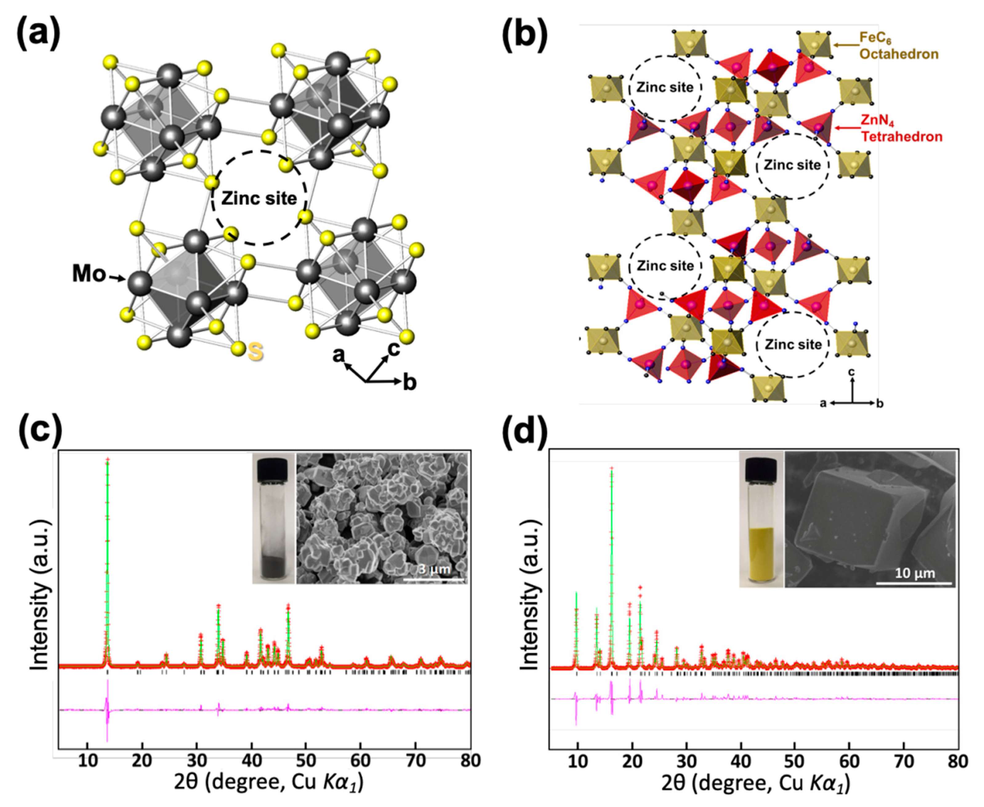
To fundamentally solve such problems, here we propose using an intercalation-type anode material instead of zinc metal and demonstrate a successful prototype of a rocking-chair zinc-ion battery system that is theoretically free from a dendrite formation. In this work, zinc Chevrel phase Zn2Mo6S8 and zinc hexacyanoferrate Kx(H2O)0.22Zn3[Fe(CN)6]2 (named as ZPB) are adopted as anode and cathode, respectively. Zinc Chevrel phase Zn2Mo6S8 (Figure 1a) was considered as an anode material because it is a highly stable intercalation-type host material with a low operating voltage (0.35 V vs. Zn/Zn2+), moderate capacity (128 mAh g−1), and high Coulombic efficiency in ZnSO4-based aqueous electrolyte (Figure S2) [12]. The cathode material ZPB was proven to be an attractive cathode material for ZIBs because of its high operating voltage (1.75 V vs. Zn/Zn2+) and porous structure formed by three-dimensional networks of FeC6 octahedra and ZnN4 tetrahedra via C≡N ligands (Figure 1b), accommodating zinc ions into the large sites [13,14].
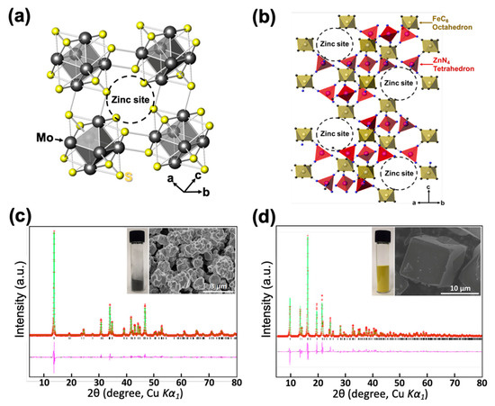
Figure 1.
(a) The crystal structure of the Chevrel phase, Mo6S8. (b) The crystal structure of zinc hexacyanoferrate (ZPB). (c) Powder X-ray Rietveld refinement profile for Mo6S8 at 25 °C, and an SEM image of the powder. (d) Powder X-ray Rietveld refinement profile for the ZPB at 25 °C, and an SEM image of the particles (red points: experimental data; green line: calculated data; pink line: difference; black bars: Bragg positions).
2. Experimental
2.1. Synthesis of Materials
The anode material, zinc Chevrel phase Zn2Mo6S8, was obtained by electrochemical zinc insertion into Mo6S8 that was prepared by chemical oxidation (Cu extraction) of Cu2Mo6S8 by stirring its powder overnight in 1 M aqueous solution of FeCl3, as described in our previous work [12]. Cu2Mo6S8 was prepared by solid-state synthesis from a stoichiometric mixture of copper powder (99.7%, Aldrich, St. Louis, MO, USA), molybdenum powder (99.9%, Aldrich) and sulfur powder (99.98%, Aldrich) at 1050˚C for two days in a vacuum-sealed fused-silica tube.
The cathode material, rhombohedral zinc hexacyanoferrate (Prussian-blue analogue), was synthesized according to a previously reported method [13]. An aqueous solution of ZnSO4·6H2O (≥99.0%, Sigma-Aldrich) (1.3 M, 10 mL) was slowly added into an aqueous solution of 0.5 M K3[Fe(CN)6] 3H2O (≥99.0%, Sigma-Aldrich) (0.5 M, 20 mL) with vigorous stirring at 60 °C, immediately producing insoluble colloidal products. The stirring was continued for about 30 min until a homogeneous yellow-colored product was obtained. The final product was washed with distilled water by centrifuging at 6000 rpm for 15 min three times to remove any unreacted soluble species. The powder was finally dried in a vacuum oven at 80 °C overnight.
2.2. Electrochemical Characterization
Electrochemical measurements were conducted with three-electrode cells. The working electrode consists of the host material (ZPB or Mo6S8), conductive carbon (Super P carbon black, Timcal Graphite & Carbon, Bodio, Switzerland), and a poly(vinylidene difluoride) binder (W#1300, Kureha Co., Osaka, Japan) (8:1:1 weight ratio). The mixture was dispersed in N-methyl-2-pyrrolidone (NMP) to form a slurry that was cast onto carbon-coated thin stainless steel foil (SUS-316L, Wellcos Co., Gunpo-si, Korea) as the current collector, dried at 80 °C in an oven for 10 h to completely remove the NMP solvent. Then, the electrodes were pressed by an electrode rolling machine (Wellcos Co., Korea). The loading of each active material for the electrode was 4.16 mg and 22.88 mg for ZPB and Mo6S8, respectively, with an electrode area of 1.53 cm2. For a half-cell experiment, a zinc metal disc (1 mm thickness) and zinc rod (3.18 mm diameter) were used as the counter and the reference electrode, respectively. A glass fiber was used as a separator (GF/A, Whatman, Maidstone, UK) and 0.1 M Zn(SO4)2 aqueous solution (Aldrich) as the electrolyte. The electrolyte has an electrochemical window of ~2 V vs. Zn/Zn2+ (Figure S3), enabling us to utilize the high-voltage ZPB material as the cathode. To prepare negative Zn2Mo6S8 electrodes to be used for a full-cell measurement, Mo6S8 electrodes were first electrochemically reduced to 0.25 V vs. Zn/Zn2+ in the half-cell set-up, followed by washing with distilled water. Cyclic voltammetry and galvanostatic discharge-charge measurements were performed using the EC-Lab software on a Biologic VMP3 multichannel potentiostat (Biologic Science Instruments SAS, Seyssinet-Pariset, France). The galvanostatic charging and discharging were performed with a constant-current mode.
2.3. Materials Characterization
Powder X-ray diffraction (XRD) data were collected at room temperature on a Rigaku Miniflex 600 diffractometer with a Cu X-ray tube (λ = 1.5418 Å), a secondary graphite-monochromator, and the angular range of 10° ≤ 2θ ≤ 70° for a general purpose. For the structural determination of the zinc-inserted ZPB phase (=Zn0.72ZPB), a PANalytical Empyrean X-ray diffractometer was used with a Cu Kα1 X-ray (λ = 1.5406 Å) with a Ge (111) monochromator, position-sensitive PIXcel3D 2x2 detector, the angular range of 5° ≤ 2θ ≤ 80°, step 0.013000°, and total measurement time of 9 h at room temperature. The crystal structures for the synthesized ZPB phase was confirmed using the powder profile refinement program GSAS [42]. Determination of the crystal structure of Zn0.72ZPB was performed using a combination of the powder profile refinement program GSAS and the single-crystal structure refinement program CRYSTALS [43], in a similar way to that described in our previous work [12]. For a three-dimensional view of the Fourier density maps, MCE [44] was used. Le Bail fitting was carried out with a structural model of ZPB. The structure factors were extracted, which were used as input data for the single crystal refinement program, CRYSTALS. Then, the position of the inserted Zn atom was determined from the Fourier difference synthesis map, completing the structural model for Zn0.72ZnPB. Finally, Rietveld refinement was applied.
The morphology and elemental compositions of samples were analyzed by high-resolution field-emission scanning microscopy (HR FE-SEM, Hitachi SU-8020) with an energy dispersive X-ray spectrometry (EDX) attachment, and inductively coupled plasma analysis (ICP, Varian 700-ES). Thermogravimetric analysis (TGA, Rigaku TG 8120) was performed to determine the amount of water of the samples.
3. Results and Discussion
3.1. Characterization of the Synthesized Materials
The synthesized Mo6S8 phase was confirmed using powder X-ray Rietveld refinement as presented in Figure 1c with its SEM image in the inset and Figure S4, where no impurities are observable. The particle sizes are in the range 200–900 nm. The crystal structure of Mo6S8 is trigonal with the space group of R-3 and the refined lattice parameters of a = 9.1952(1) Å, and c = 10.8825(3) Å, in good agreement with the previous report [12]. The refined atomic parameters and selected interatomic distances are summarized in Tables S1 and S2.
The ZPB phase was synthesized without impurity and confirmed by the powder X-ray Rietveld refinement as shown in Figure 1d with its SEM image in the inset. The particles are well segregated with their sizes in the range of 10−20 μm (Figure S5). Its crystal structure is trigonal with the space group of R-3c and the refined lattice parameters of a = 12.6006(3) Å, and c = 32.9652(12) Å, in good agreement with a previous study [45]. The refined atomic parameters and selected interatomic distances are summarized in Tables S3 and S4. The metal compositions of the ZPB phase were determined using the ICP analysis (Table S5) and the water content was determined by TGA (Figure S6). The chemical formula of the initially synthesized ZPB is K0.02(H2O)0.22Zn2.94[Fe(CN)6]2.
3.2. Characterization of the Anode Material in a Half-Cell
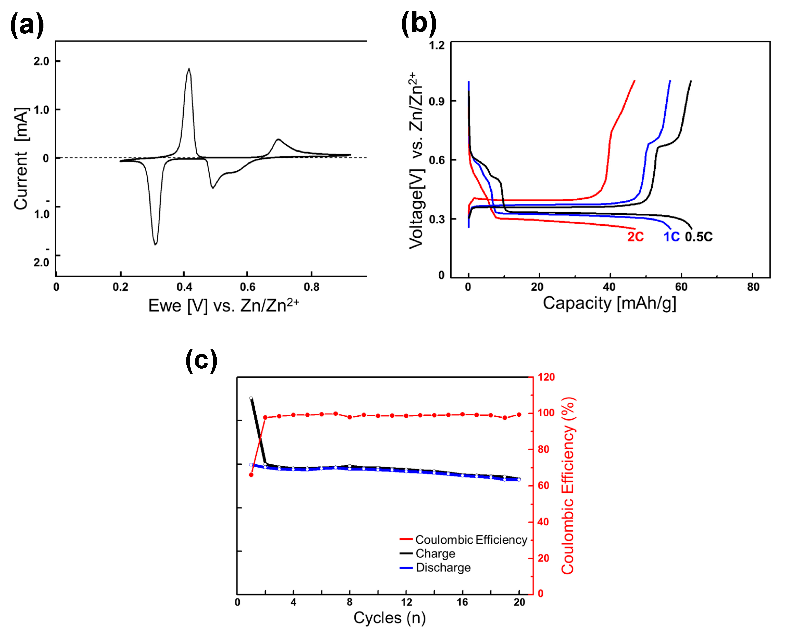
The electrochemical properties of zinc intercalation into Mo6S8 have previously been thoroughly studied [12]. The material prepared in this work shows the same features as before according to cyclic voltammogram (CV), galvanostatic discharge-charge curves, and cycling performance in zinc half-cells, as presented in Figure 2a–c, where the n C rate is defined as the rate of charge (or discharge) at which the charge (or discharge) is completed in (1/n) hours. Here, the 1 C rate was defined as 128 mA g−1 because the theoretical capacity of the four-electron reaction from Mo6S8 to Zn2Mo6S8 is 128 mAh g−1.
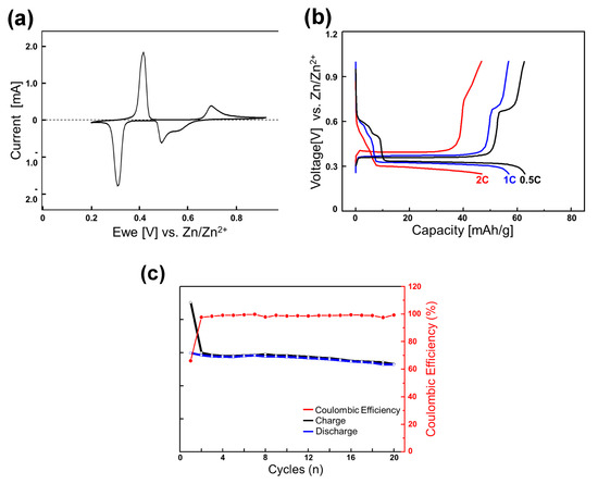
Figure 2.
(a) Cyclic voltammograms of the Mo6S8 electrode for the initial cycle at 0.05 mV s−1 with zinc metal as the counter and reference electrode in 0.1 M ZnSO4 aqueous electrolyte; (b) reversible discharge-charge cycles at various C rates (the second cycle); and (c) cycling performance at 0.1 C rate.
To briefly summarize its characteristics, the electrochemical zinc-ion insertion into Mo6S8 occurs in a stepwise fashion. ZnMo6S8 first forms from Mo6S8 in the higher-voltage region at around 0.45−0.50 V vs. Zn/Zn2+. The inserted zinc ions occupied the interstitial sites in cavities surrounded by sulfur atoms (Zn1 sites). A significant number of the inserted zinc ions were trapped in these Zn1 sites, giving rise to the first-cycle irreversible capacity of ∼46 mAh g−1 out of the discharge capacity of 134 mAh g−1 at a current of 6.4 mA g−1. In the lower-voltage region, further insertion into Zn2 sites occurs to form Zn2Mo6S8 at around 0.35 V, also involving a two-phase reaction. The electrochemical insertion and extraction into the Zn2 sites appeared to be reversible and fast.
In the rocking-chair full-cell experiments that will be discussed later (vide infra), we use the zinc-inserted phase Zn2-δMo6S8 (0 < δ << 1) as the initial anode material and intend to utilize only the lower voltage (0.35 V) region by adopting a high N/P ratio (5.5/1) that is sufficient for the anode voltage to be maintained at 0.35 V during cycles. We chose a slightly zinc-deficient phase (0 < δ << 1), not fully inserted (discharged) Zn2Mo6S8, to avoid the end region of the discharge profile where the voltage varies sensitively by the Zn content (see Figure 2b).
3.3. Characterization of the Cathode Material in a Half-Cell
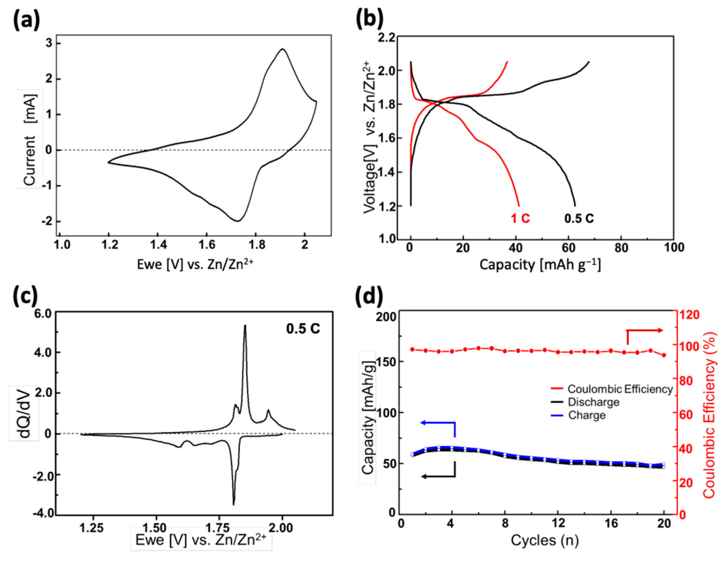
Figure 3a shows the CV profile of the ZPB electrode in the range of 1.20–2.05 V (vs. Zn/Zn2+), with a scan rate of 1 mV s−1. The initial open-circuit voltage of the electrode was 1.81 V, and a negative sweep was first applied. There is just broad and seemingly overlapping cathodic (zinc-insertion) peaks with its maximum current at 1.72 V, and the corresponding anodic (zinc-extraction) peak at 1.91 V. The shape of each peak appears to contain more than two overlapping peaks, implying a mechanism involving multiple intercalation stages during the zinc insertion/deinsertion.
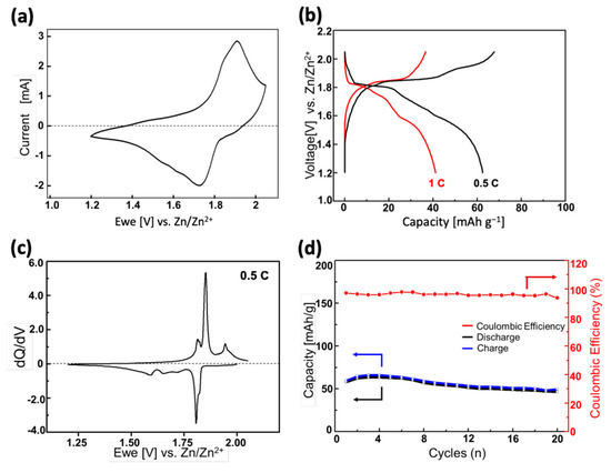
Figure 3.
(a) Cyclic voltammograms of the ZPB electrode at 1 mV s−1 with zinc metal as the counter and reference electrode in 0.1 M ZnSO4 aqueous electrolyte; (b) initial discharge-charge cycles at various C rates; (c) dQ/dV curves corresponding to the profiles in (b); (d) cycling performance at 0.5 C rate.
The galvanostatic discharge-charge profiles of the ZPB electrodes with two different C-rates are shown in Figure 3b. Here, the 1 C rate is defined as 84.4 mA g−1, because the theoretical capacity of the two-electron reaction (one zinc insertion) per formula unit of ZPB is 84.4 mAh g−1. Multiple quasi-plateaus are seen in the discharge curves, which are more clearly seen in the dQ/dV curve (Figure 3c). The difference between Figure 3a,c is noteworthy, and appears to come from the measurement speed. The total time for a full cycle is about three times slower for the latter, resulting in the sharp peaks in Figure 3c. The zinc insertion/deinsertion into/from the host ZPB structure seems complicated involving multiple stages. Five cathodic peaks are observed: two sharp peaks at ~1.82 and 1.80 V with a partial overlapping, and three broader peaks at 1.72, 1.65, and 1.59 V. On the other hand, only four anodic peaks are observed at ~1.94 1.85, 1.83, and 1.81 V. The sharpest and most intense redox couple (1.80 V and 1,85 for cathodic and anodic currents, respectively) has a lower polarization than the redox couple at higher voltage (1.82 and 1.94 V), indicating relatively fast kinetics of the insertion-deinsertion reactions. The three broad cathodic peaks at lower voltage region (1.72, 1.65, and 1.59 V) seem to correspond to the two overlapping peaks at 1.83, and 1.81 V, implying that the insertion reaction at the lower voltage region is more sluggish than the deinsertion reaction. The reason for this difference between the insertion and deinsertion stages is not apparent, and a further study will be necessary to understand the mechanism better.
In Figure 3b, the discharge capacity 62.5 mAh g−1 at a 0.5 C rate decreases to 41.2 mAh g−1 at 1.0 C rate, showing a low rate-performance, similar to the sodium-ion intercalation into the same host material [46]. The cycle performance of the ZPB electrode is displayed in Figure 3d. The capacity retention is 81% at the 10th cycle. Considering that the particle size decreased after 50 cycles, as evidenced in XRD and SEM images (Figure S7), the insertion of zinc ions seems to involve mechanical stress due to the high charge of zinc ions [47] or the significant anisotropic lattice changes of the structure during cycles, which that will be discussed later (vide infra), resulting in the low rate-performance.
3.4. Elemental Analysis of the Cathode Material
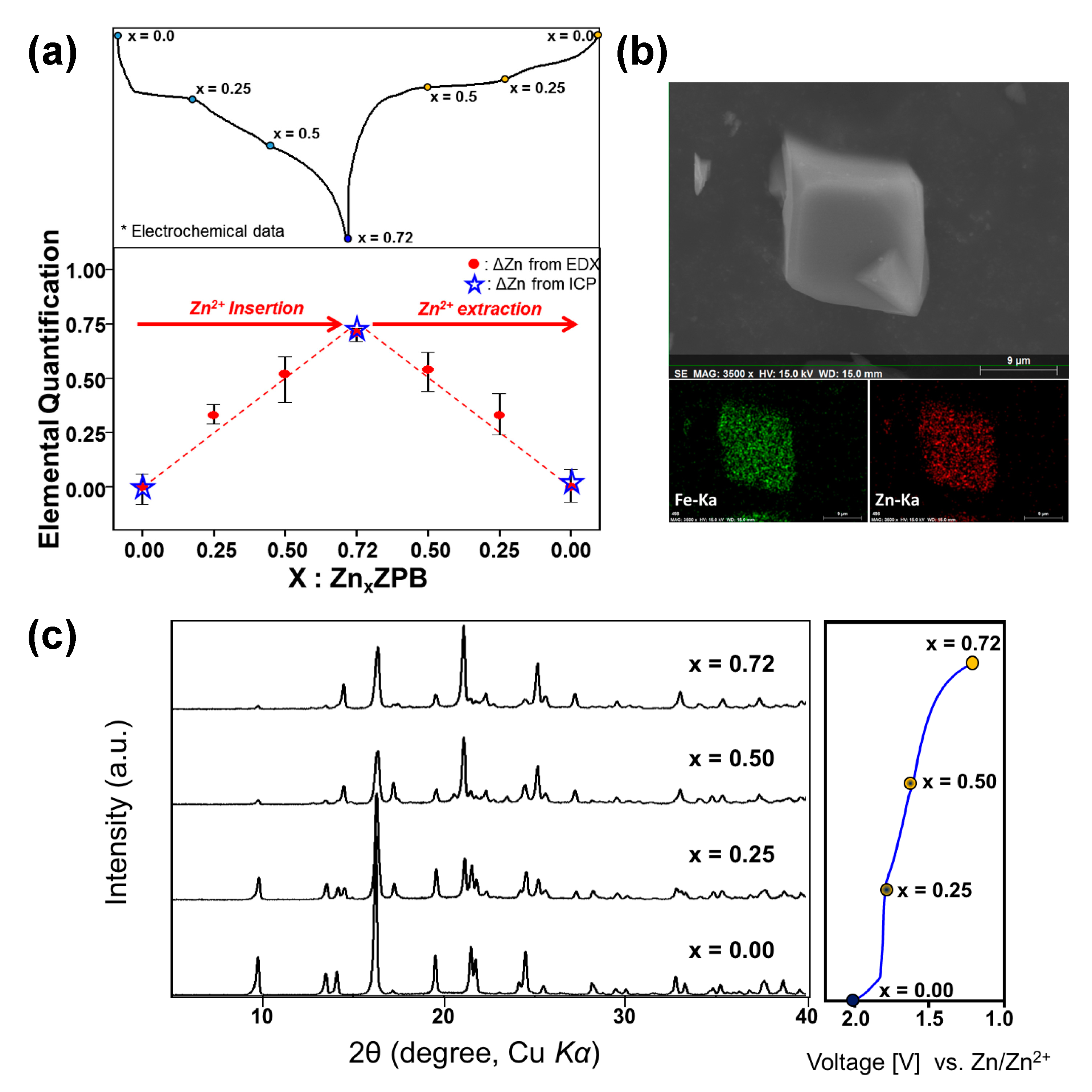
To quantify the zinc content in ZPB during the electrochemical zinc insertion-deinsertion process, we performed EDX FE-SEM and ICP analyses for several samples taken at a different state of charge (Figure 4a and Tables S6 and S7). The analyzed zinc amount matches very well with that calculated from the discharge/charge capacity. The elemental mapping for the fully discharged electrode (Figure 4b) shows a uniform distribution of zinc atoms in the particles.
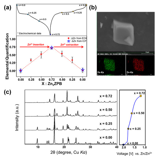
Figure 4.
(a) Zn atomic ratios for ZnxZPB electrode samples during a discharge-charge cycle, where the x values were estimated from ICP and FE-SEM EDX elemental analyses; (b) EDX elemental mapping of Zn0.72ZPB; (c) XRD patterns of ZnxZPB (x = 0, 0.25, 0.50, and 0.72) during discharging.
Prussian-blue analogues easily intercalate/deintercalate zeolitic water into/from its crystal structure, and its water content is dependent on synthetic and environmental conditions [15,48]. The initial ZPB phase contains a small amount of water content (0.22 H2O per formula unit of ZPB) according to TGA analysis (Figures S6 and S8). However, when the ZPB electrode is inside the aqueous cell, water molecules must be intercalated into the structure, which is evidenced by TGA and XRD analyses (Figure S8). Two samples are compared: just a wetted electrode (in principle, equivalent to a fully recharged electrode) and a fully discharged electrode in the electrolyte. The determined water content is 8.3 moles per formula unit of ZPB for both samples, suggesting that once water is intercalated into the host structure in the electrolyte, the water content is maintained during the cycle, similar to the nickel Prussian-blue analogue [15]. The wetted electrode shows a slight change in XRD pattern from the pristine one, confirming that the water is genuinely intercalated, not merely adsorbed on the surface of the particles. The chemical formula of the wetted ZPB is K0.02(H2O)8.3Zn2.94[Fe(CN)6]2, the structure of which was also confirmed with the Rietveld refinement as presented in Figure S9, and Tables S8 and S9. Its structure is the same as the pristine ZPB except that the occupancy of the water increases.
3.5. Structural Analysis of the Cathode Material
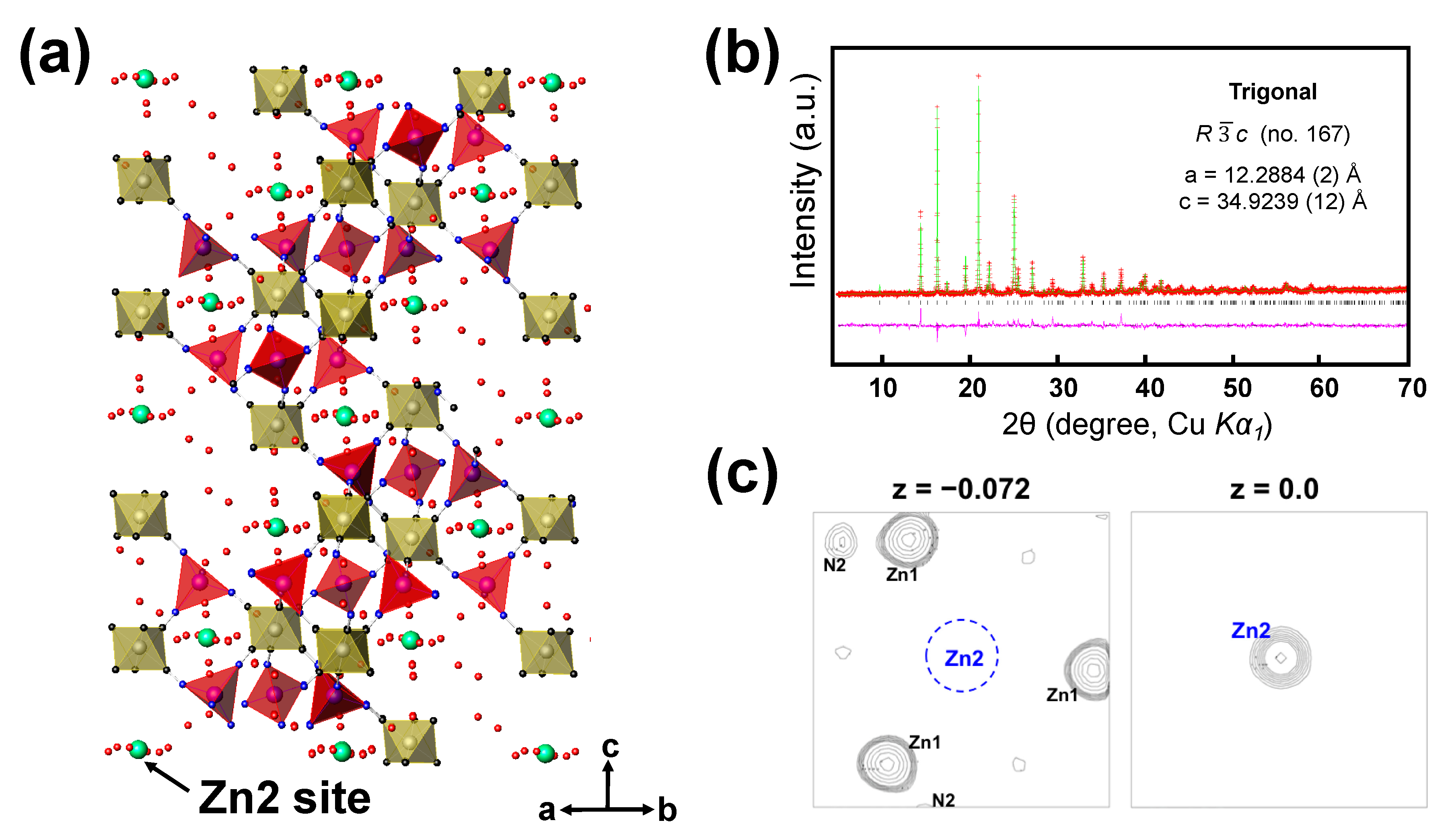
The zinc-inserted phase can be formulated as ZnxK0.02(H2O)8.3Zn2.94[Fe(CN)6]2 (named as ZnxZPB, 0 ≤ x ≤ 0.72). The just-wetted phase is expressed as Zn0ZPB to distinguish it from the pristine ZPB phase. The powder XRD patterns of the ZnxZPB electrodes were recorded with respect to the number of inserted zinc ions (x = 0, 0.25, 0.5, and 0.72) employed during the galvanostatic reduction, as shown in Figure 4c. Unlike cubic Prussian-blue analogues [15,48], the evolution of the patterns is complicated due to multiple insertion stages, as implied by the multiple quasi-plateaus in the discharge profile. An atomic-scale structural analysis would be crucial to understanding the insertion mechanism. In this work, the crystal structure of the fully reduced phase Zn0.72ZPB was determined and refined for the first time using similar crystallographic techniques described in our earlier work [12], with a particular interest in the location and environment of the inserted Zn ions. The crystal structure of Zn0.72ZPB and Rietveld refinement profile are shown in Figure 5a,b, respectively. The refined parameters are summarized in Table S10, with interatomic distances in Table S11. The a and c parameters are anisotropically changed from the initial Zn0ZPB phase (a is decreased by 2.44% while c is increased by 5.98%), while the unit cell volume is almost kept (increased by 0.86%). It is also noted that Zn0.72ZPB has a distinct structure compared to other related phases AxZnPB (A = Na+, K+, Rb+, Cs+). The inserted Zn ion is located at 6b Wyckoff position (0, 0, 0) as clearly evidenced by the Fourier difference map (Figure 5c), whereas other A cations are in a disordered site, forming six-membered rings inside the large cavities in the structure [45,49,50,51] (see Figure S10 for a graphical illustration).
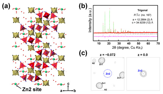
Figure 5.
(a) The crystal structure of Zn0.72ZPB, with FeC6 octahedra (yellow), ZnN4 tetrahedra (red), and inserted Zn2 atoms (green). (b) The powder X-ray Rietveld refinement profile for Zn0.72ZPB, recorded at 25 °C (Red points: experimental data; green line: calculated data; pink line: difference; and bars: Bragg positions). (c) (001) sections of observed Fourier map at z = −0.072 (left) and difference Fourier maps at z = 0.0 (right) for the Zn0.72ZPB phase at the refinement stage prior to the location of Zn2 atoms. The map width is 10 Å, and the center of the left map is at (0, 0, −0.072). The contour levels are adjusted unequally for clarity. Zn2 is identified from the right plane that is above the left plane by 2.51 Å (Δz = 0.072). The minimum and maximum contour levels are (a) 2.71 and 20.1 e/Å3, and (b) 2.71 and 14.5 e/Å3.
3.6. Rocking-Chair Zn-Ion Battery Cell
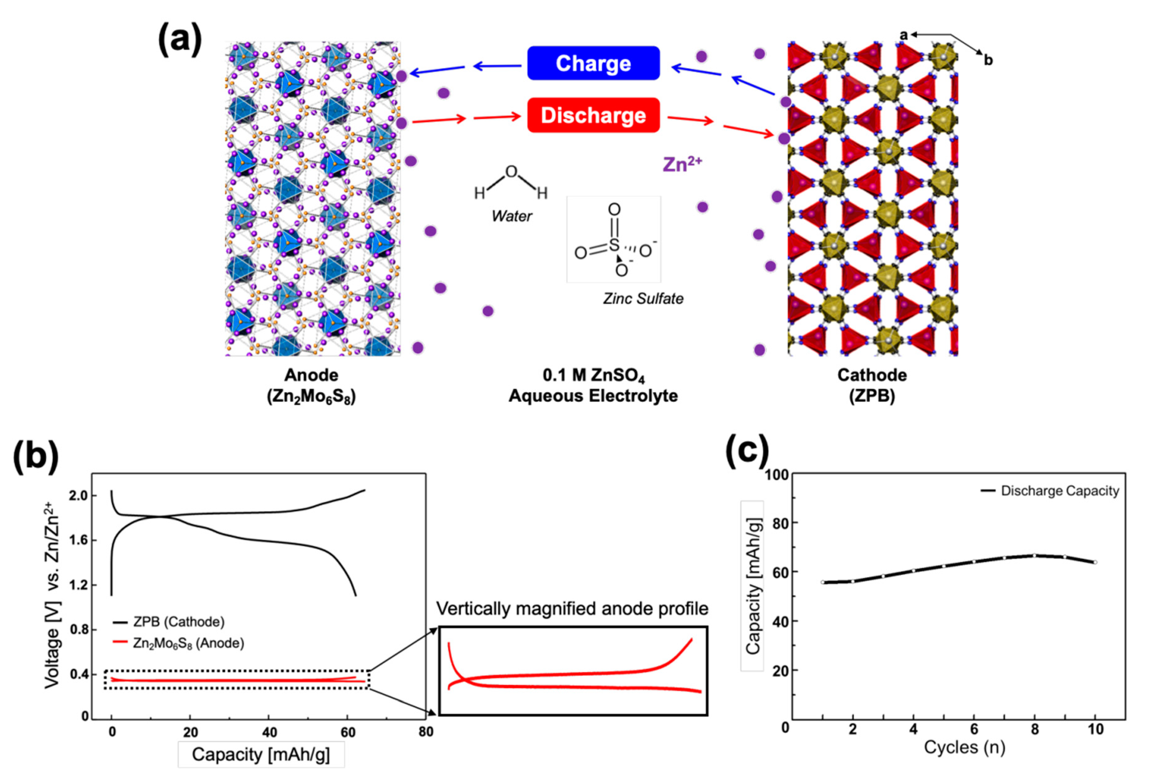
A prototype of the rocking-chair zinc-ion cell was constructed in a three-electrode system with the Zn2Mo6S8 anode (counter electrode), ZPB cathode (working electrode), and the zinc reference electrode in 0.1 M ZnSO4 aqueous electrolyte (Figure S11). A large voltage gap between the cathode and anode is preferred to design a high-energy rocking-chair cell. Zn2Mo6S8 was adopted for its low operating voltage at 0.35 V and ZPB for its high voltage around 1.75 V (vs. Zn/Zn2+). The electrochemical system is schematically presented in Figure 6a.
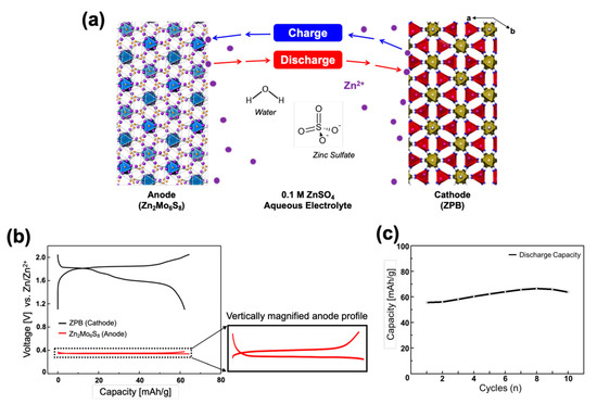
Figure 6.
(a) Illustration of the compositions for the rocking-chair zinc-ion battery: Zn2Mo6S8 as an anode and ZPB as a cathode. (b) Initial discharge-charge profiles of a Zn2Mo6S8/ZPB cell at 0.2 C rate with the zinc metal reference electrode. The vertical magnification of the anode profile is ~13 times. (c) Cycling performance of Zn2Mo6S8/ZPB cells at 0.5 C rate.
The cell was designed to be a positive-electrode limiting cell by making a sufficiently high negative/positive (N/P) electrode mass ratio of 5.5/1 (equivalent to the capacity ratio of 7.74/1) to reduce parameters affecting the cell performance: in this case the anode potential is constant, and its capacity is much larger than the cathode, so that the cell voltage and capacity is dependent only on the cathode performance. However, it should be pointed out that the N/P ratio is not optimized, and such a high ratio is not practical, either, because it reduces the energy density of the cell significantly, considering that an N/P capacity ratio in practical LIBs is mostly within the range of 1.05–1.2. The effects of various N/P ratios on the cell performance should be investigated systematically as a further study. Figure 6b shows the discharge-charge profiles of the cell where the profiles on each electrode are respectively presented. The negative electrode shows a flat pattern at 0.35 V. The cell shows a capacity of 62.3 mAh g−1 when it is discharged to 1.10 V (vs. Zn/Zn2+) and recharged up to 2.05 V with 0.2 C rate. Because of the flat anode voltage, the cell voltage profile is almost the same as the cathode profile in shape, but the cell voltage is just smaller by 0.35 V.
Therefore, the suggested electrochemical reactions on each electrode can be expressed as:
where δ is small (0 < δ << 1), and the amount (x) of the reversible zinc ions is in the range 0 ≤ x ≤ 0.72 within the cell voltage window 0.75–1.70 V. The discharge-charge profile for a two-electrode cell also shows a reversible cycle with an average discharge voltage of ~1.40 V (Figure S12). Cycling performance of the full-cell is shown in Figure 6c. It shows a similar tendency to that for the ZnPB half-cell presented in Figure 2d. Because of the low cycling performance of the cathode, the full-cell is also not expected to be better. The long-term cycle stability of the cell should be investigated further as a future study. Nonetheless, the rocking-chair Zn-ion battery cell is successfully demonstrated for the first time, to the best of our knowledge.
Cathode: x Zn2+ + Zn0ZPB + 2x e− ↔ ZnxZPB
Anode: Zn2−δMo6S8 ↔ Zn2−δ−xMo6S8 + x Zn2+ + 2x e−
The energy density of the present cell with high N/P capacity ratio (7.74/1) is estimated at 13 Wh kg−1 based on the mass loading of the active materials (4.16 mg of cathode, 22.88 mg of anode), the cell capacity (0.259 mAh/cell), and voltage (1.40 V), not taking into account the mass of electrolytes and current collectors. The energy density of a simulated cell with a practical N/P capacity ratio (e.g., 1.20/1) could be 47 Wh kg−1, which is comparable to those for lead-acid batteries. For comparison, the energy density of a LIB cell with 1.20/1 capacity ratio is estimated to be 367 Wh kg−1 (150 mAh −1 for LiCoO2, 350 mAh g−1 for graphite, and the discharge voltage of 3.7 V).
4. Conclusions
To develop ZIB cells that are theoretically free from the zinc dendrite problem, we propose adopting an intercalation-type anode material instead of zinc metal and demonstrate a successful prototype of a rocking-chair zinc-ion battery system employing Zn2Mo6S8 as the anode operating at 0.35 V, and K0.02(H2O)0.22Zn2.94[Fe(CN)6]2 (ZPB) as the cathode operating at 1.75 V (vs. Zn/Zn2+) in ZnSO4 aqueous electrolyte. The demonstration cell is designed to be positive-limited with the N/P mass ratio of 5.5:1 to reduce factors influenced by the negative material. The full-cell shows a reversible cycle, with a capacity of 62.3 mAh g−1 and an average discharge cell voltage of ~1.40 V. Considering the high cost of molybdenum, Zn2Mo6S8 is unlikely to be the best choice as an anode material. Nonetheless, this work is the first proof-of-concept, and may motivate further developments of rocking-chair ZIB batteries adopting electrode materials with higher performance than the materials demonstrated in this work.
Supplementary Materials
The following are available online at http://www.mdpi.com/2313-0105/5/1/3/s1, Figure S1: SEM images of the zinc anode before and after 20 cycles, Figure S2: Coulombic efficiencies for zinc metal and Mo6S8 in 0.1M ZnSO4 or 1M ZnSO4 aqueous electrolytes, Figure S3: Cyclic voltammogram of 0.1M ZnSO4 aqueous electrolyte. Pt was used as the working electrode at 25 °C and a scan rate of 20 mV s–1, Figure S4: SEM images of synthesized Mo6S8 powder, Figure S5: SEM images of the synthesized zinc hexacyanoferrate (ZPB) particles, Figure S6: Thermogravimetric analysis for K0.02(H2O)0.22Zn2.94[Fe(CN)6]2 (ZPB) under nitrogen flowing atmosphere and XRD patterns to check structural stability (rate = 10 oC/min), Figure S7: SEM images of XRD patterns of ZPB electrodes before and after 25cycles, Figure S8: (Left) Thermogravimetric analysis for K0.02(H2O)0.22Zn2.94[Fe(CN)6]2 (ZPB) and ZnxK0.02(H2O)8.3Zn2.94 [Fe(CN)6]2 (ZnxZPB) (x = 0, 0.72)phases under nitrogen flowing atmosphere. (Right) XRD patterns of raw (ZPB) and its wetted phase (Zn0ZPB), Figure S9: Powder XRD Rietveld refinement profile for the wetted ZPB phase, K0.02(H2O)8.3Zn2.94[Fe(CN)6]2 (= Zn0ZPB) at room temperature, Figure S10: Structural illustration for intercalation position of various gest ions (a) Na+, (b) Rb+, (c) K+, (d) Zn2+, Figure S11: The schematic design of Zn2Mo6S8/ZnPB full cell system, and the photographic images of the beaker-type cell and its components used in this work, Figure S12: Galvanostatic curves of the Zn2Mo6S8/ZnPB full cell at 0.5C-rate. Note that the voltage is the cell voltage (the difference between the cathode and anode), Table S1: Crystallographic data and Rietveld refinement results of Mo6S8 powder: atomic coordinates, site occupancies, isotropic displacement parameters and reliability factors at room temperature, Table S2: Selected interatomic distances (Å) in the crystal structure of Mo6S8 at room temperature, Table S3: Crystallographic data and powder XRD Rietveld refinement results for K0.02(H2O)0.22Zn2.94[Fe(CN)6]2 (ZPB) powder: atomic coordinates, site occupancies, isotropic displacement parameters and reliability factors at room temperature, Table S4: Selected interatomic distances (Å) in the structure of K0.02(H2O)0.22Zn2.94[Fe(CN)6]2 (ZPB) at room temperature, Table S5: Elemental ratios estimated from ICP (Inductively coupled plasma) analysis for K0.02(H2O)0.22Zn2.94[Fe(CN)6]2 (ZPB) powder, Table S6: Quantitative HR FE-SEM EDX data from which the (Zn/Fe) atomic ratios were estimated for each electrode sample of ZnxK0.02(H2O)8.3Zn2.94[Fe(CN)6]2 (ZnxZPB) (x = 0, 0.25, 0.50, 0.72) during discharge/charge cycle, Table S7: Elemental ratios estimated from ICP (Inductively coupled plasma) analysis for K0.02(H2O)0.22Zn2.94 [Fe(CN)6]2 (ZPB), ZnxK0.02(H2O)8.3Zn2.94[Fe(CN)6]2 (ZnxZPB) samples (x = 0.72 and 0), Table S8: XRD powder diffraction and Rietveld refinement results for the wetted ZPB phase, K0.02(H2O)8.3Zn2.94[Fe(CN)6]2 (= Zn0ZPB): atomic coordinates, unit-cell parameters, site occupancies, isotropic displacement parameters and reliability factors from the Rietveld refinement, Table S9: Selected interatomic distances (Å) for the wetted ZPB phase, K0.02(H2O)8.3Zn2.94[Fe(CN)6]2 (Zn0ZPB) at room temperature, Table S10: XRD powder diffraction and Rietveld refinement results for Zn0.72ZPB sample: atomic coordinates, unit-cell parameters, site occupancies, isotropic displacement parameters and reliability factors from the Rietveld Refinement, Table S11: Selected interatomic distances (Å) in Zn0.72ZPB at room temperature.
Author Contributions
M.S.C. carried out the experiments. M.S.C. and S.-T.H. discussed about the data analysis and wrote the manuscript.
Funding
This research was supported by the Creative Materials Discovery Program through the National Research Foundation of Korea (NRF) funded by the Ministry of Science, ICT and Future Planning (2015M3D1A1069707).
Conflicts of Interest
The authors declare no conflicts of interest.
References
- Amine, K.; Kanno, R.; Tzeng, Y. Rechargeable lithium batteries and beyond: Progress, Challenges, and future directions. MRS Bull. 2014, 39, 395–405. [Google Scholar] [CrossRef]
- Kundu, D.; Talaie, E.; Duffort, V.; Nazar, L.F. The Emerging Chemistry of Sodium Ion Batteries for Electrochemical Energy Storage. Angew. Chem. Int. Ed. 2015, 54, 3431–3448. [Google Scholar] [CrossRef] [PubMed]
- Panchal, S.; Mathew, M.; Fraser, R.; Fowler, M. Electrochemical thermal modeling and experimental measurements of 18650 cylindrical lithium-ion battery during discharge cycle for an EV. Appl. Therm. Eng. 2018, 135, 123–132. [Google Scholar] [CrossRef]
- Kubota, K.; Dahbi, M.; Hosaka, T.; Kumakura, S.; Komaba, S. Towards K-Ion and Na-Ion Batteries as “Beyond Li-Ion”. Chem. Rec. 2018, 18, 459–479. [Google Scholar] [CrossRef] [PubMed]
- Whittingham, M.S.; Siu, C.; Ding, J. Can Multielectron Intercalation Reactions Be the Basis of Next Generation Batteries? Acc. Chem. Res. 2018, 51, 258–264. [Google Scholar] [CrossRef] [PubMed]
- Canepa, P.; Gautam, G.S.; Hannah, D.C.; Malik, R.; Liu, M.; Gallagher, K.G.; Persson, K.A.; Ceder, G. Odyssey of multivalent cathode materials: Open questions and future challenges. Chem. Rev. 2017, 117, 4287–4341. [Google Scholar] [CrossRef] [PubMed]
- Xu, C.; Li, B.; Du, H.; Kang, F. Energetic zinc ion chemistry: The rechargeable zinc ion battery. Angew. Chem. Int. Ed. 2012, 51, 933–935. [Google Scholar] [CrossRef] [PubMed]
- Yuan, C.; Zhang, Y.; Pan, Y.; Liu, X.; Wang, G.; Cao, D. Investigation of the intercalation of polyvalent cations (Mg2+, Zn2+) into lambda-MnO2 for rechargeable aqueous battery. Electrochim. Acta 2014, 116, 404–412. [Google Scholar] [CrossRef]
- Lee, J.; Ju, J.B.; Cho, W.I.; Cho, B.W.; Oh, S.H. Todorokite-type MnO2 as a zinc-ion intercalating material. Electrochim. Acta 2013, 112, 138–143. [Google Scholar] [CrossRef]
- Schöllhorn, R.; Kümpers, M.; Besenhard, J.O. Topotactic redox reactions of the channel type chalcogenides Mo3S4 and Mo3Se4. Mater. Res. Bull. 1977, 12, 781–788. [Google Scholar] [CrossRef]
- Gocke, E.; Schramm, W.; Dolscheid, P.; Schollhorn, R. Molybdenum Cluster Chalcogenides Mo6X8—Electrochemical Intercalation of Closed Shell Ions Zn2+, Cd2+, and Na+. J. Solid State Chem. 1987, 70, 71–81. [Google Scholar] [CrossRef]
- Chae, M.S.; Heo, J.W.; Lim, S.-C.; Hong, S.-T. Electrochemical Zinc-Ion Intercalation Properties and Crystal Structures of ZnMo6S8 and Zn2Mo6S8 Chevrel Phases in Aqueous Electrolytes. Inorg. Chem. 2016, 55, 3294–3301. [Google Scholar] [CrossRef] [PubMed]
- Zhang, L.; Chen, L.; Zhou, X.; Liu, Z. Towards High-Voltage Aqueous Metal-Ion Batteries Beyond 1.5 V: The Zinc/Zinc Hexacyanoferrate System. Adv. Energy Mater. 2015, 5, 1400930. [Google Scholar] [CrossRef]
- Zhang, L.; Chen, L.; Zhou, X.; Liu, Z. Morphology-Dependent Electrochemical Performance of Zinc Hexacyanoferrate Cathode for Zinc-Ion Battery. Sci. Rep. 2015, 5, 18263. [Google Scholar] [CrossRef]
- Chae, M.S.; Heo, J.W.; Kwak, H.H.; Lee, H.; Hong, S.-T. Organic electrolyte-based rechargeable zinc-ion batteries using potassium nickel hexacyanoferrate as a cathode material. J. Power Sources 2017, 337, 204–211. [Google Scholar] [CrossRef]
- Trocoli, R.; Mantia, F.L. An aqueous zinc-ion battery based on copper hexacyanoferrate. ChemSusChem 2015, 8, 481–485. [Google Scholar] [CrossRef]
- Zhang, N.; Cheng, F.; Liu, Y.; Zhao, Q.; Lei, K.; Chen, C.; Liu, X.; Chen, J. Cation-Deficient Spinel ZnMn2O4 Cathode in Zn(CF3SO3)2 Electrolyte for Rechargeable Aqueous Zn-Ion Battery. J. Am. Chem. Soc. 2016, 138, 12894–12901. [Google Scholar] [CrossRef]
- Pan, C.S.; Zhang, R.X.; Nuzzo, R.G.; Gewirth, A.A. ZnNixMnxCo2-2xO4 Spinel as a High-Voltage and High-Capacity Cathode Material for Nonaqueous Zn-Ion Batteries. Adv. Energy Mater. 2018, 8, 1800589. [Google Scholar] [CrossRef]
- Pan, H.; Shao, Y.; Yan, P.; Cheng, Y.; Han, K.S.; Nie, Z.; Wang, C.; Yang, J.; Li, X.; Bhattacharya, P.; et al. Reversible aqueous zinc/manganese oxide energy storage from conversion reactions. Nat. Energy 2016, 1, 16039. [Google Scholar] [CrossRef]
- He, P.; Yan, M.; Zhang, G.; Sun, R.; Chen, L.; An, Q.; Mai, L. Layered VS2 Nanosheet-Based Aqueous Zn Ion Battery Cathode. Adv. Energy Mater. 2017, 7, 1601920. [Google Scholar] [CrossRef]
- Ding, J.W.; Du, Z.G.; Gu, L.Q.; Li, B.; Wang, L.Z.; Wang, S.W.; Gong, Y.J.; Yang, S.B. Ultrafast Zn2+ Intercalation and Deintercalation in Vanadium Dioxide. Adv. Mater. 2018, 30, 1800762. [Google Scholar] [CrossRef] [PubMed]
- Zhang, N.; Dong, Y.; Jia, M.; Bian, X.; Wang, Y.Y.; Qiu, M.D.; Xu, J.Z.; Liu, Y.C.; Jiao, L.F.; Cheng, F.Y. Rechargeable Aqueous Zn-V2O5 Battery with High Energy Density and Long Cycle Life. ACS Energy Lett. 2018, 3, 1366–1372. [Google Scholar] [CrossRef]
- Jo, J.H.; Sun, Y.-K.; Myung, S.-T. Hollandite-type Al-doped VO1.52(OH)0.77 as a zinc ion insertion host material. J. Mater. Chem. A 2017, 5, 8367–8375. [Google Scholar] [CrossRef]
- Kaveevivitchai, W.; Manthiram, A. High-capacity zinc-ion storage in an open-tunnel oxide for aqueous and nonaqueous Zn-ion batteries. J. Mater. Chem. A 2016, 4, 18737–18741. [Google Scholar] [CrossRef]
- Alfaruqi, M.H.; Mathew, V.; Song, J.; Kim, S.; Islam, S.; Pham, D.T.; Jo, J.; Kim, S.; Baboo, J.P.; Xiu, Z.; et al. Electrochemical Zinc Intercalation in Lithium Vanadium Oxide: A High-Capacity Zinc-Ion Battery Cathode. Chem. Mater. 2017, 29, 1684–1694. [Google Scholar] [CrossRef]
- Sambandam, B.; Soundharrajan, V.; Kim, S.; Alfaruqi, M.H.; Jo, J.; Kim, S.; Mathew, V.; Sun, Y.K.; Kim, J. Aqueous rechargeable Zn-ion batteries: An imperishable and high-energy Zn2V2O7 nanowire cathode through intercalation regulation. J. Mater. Chem. A 2018, 6, 3850–3856. [Google Scholar] [CrossRef]
- Kundu, D.; Adams, B.D.; Duffort, V.; Vajargah, S.H.; Nazar, L.F. A high-capacity and long-life aqueous rechargeable zinc battery using a metal oxide intercalation cathode. Nat. Energy 2016, 1, 16119. [Google Scholar] [CrossRef]
- Chao, D.L.; Zhu, C.; Song, M.; Liang, P.; Zhang, X.; Tiep, N.H.; Zhao, H.F.; Wang, J.; Wang, R.M.; Zhang, H.; et al. A High-Rate and Stable Quasi-Solid-State Zinc-Ion Battery with Novel 2D Layered Zinc Orthovanadate Array. Adv. Mater. 2018, 30, 1803181. [Google Scholar] [CrossRef]
- Li, W.; Wang, K.; Cheng, S.; Jiang, K. A long-life aqueous Zn-ion battery based on Na3V2(PO4)2F3 cathode. Energy Storage Mater. 2018, 15, 14–21. [Google Scholar] [CrossRef]
- Hao, J.W.; Mou, J.; Zhang, J.W.; Dong, L.B.; Liu, W.B.; Xu, C.J.; Kang, F.Y. Electrochemically induced spinel-layered phase transition of Mn3O4 in high performance neutral aqueous rechargeable zinc battery. Electrochim. Acta 2018, 259, 170–178. [Google Scholar] [CrossRef]
- Ma, L.; Chen, S.; Li, H.; Ruan, Z.; Tang, Z.; Liu, Z.; Wang, Z.; Huang, Y.; Pei, Z.; Zapien, J.A.; et al. Initiating a mild aqueous electrolyte Co3O4/Zn battery with 2.2 V-high voltage and 5000-cycle lifespan by a Co(III) rich-electrode. Energy Environ. Sci. 2018, 11, 2521–2530. [Google Scholar] [CrossRef]
- Pang, Q.; Sun, C.L.; Yu, Y.H.; Zhao, K.N.; Zhang, Z.Y.; Voyles, P.M.; Chen, G.; Wei, Y.J.; Wang, X.D. H2V3O8 Nanowire/Graphene Electrodes for Aqueous Rechargeable Zinc Ion Batteries with High Rate Capability and Large Capacity. Adv. Energy Mater. 2018, 8, 1800144. [Google Scholar] [CrossRef]
- Peng, Z.; Wei, Q.L.; Tan, S.S.; He, P.; Luo, W.; An, Q.Y.; Mai, L.Q. Novel layered iron vanadate cathode for high-capacity aqueous rechargeable zinc batteries. Chem. Commun. 2018, 54, 4041–4044. [Google Scholar] [CrossRef] [PubMed]
- Lu, W.; Xie, C.; Zhang, H.; Li, X. Zinc dendrites Inhibition for Zinc-based Battery. ChemSusChem 2018, 11, 1–12. [Google Scholar] [CrossRef] [PubMed]
- Li, H.; Xu, C.; Han, C.; Chen, Y.; Wei, C.; Li, B.; Kang, F. Enhancement on Cycle Performance of Zn Anodes by Activated Carbon Modification for Neutral Rechargeable Zinc Ion Batteries. J. Electrochem. Soc. 2015, 162, A1439–A1444. [Google Scholar] [CrossRef]
- Kang, L.; Cui, M.; Jiang, F.; Gao, Y.; Luo, H.; Liu, J.; Liang, W.; Zhi, C. Nanoporous CaCO3 Coatings Enabled Uniform Zn Stripping/Plating for Long-Life Zinc Rechargeable Aqueous Batteries. Adv. Energy Mater. 2018, 8, 1801090. [Google Scholar] [CrossRef]
- Gupta, T.; Kim, A.; Phadke, S.; Biswas, S.; Luong, T.; Hertzberg, B.J.; Chamoun, M.; Evans-Lutterodt, K.; Steingart, D.A. Improving the cycle life of a high-rate, high-potential aqueous dual-ion battery using hyper-dendritic zinc and copper hexacyanoferrate. J. Power Sources 2016, 305, 22–29. [Google Scholar] [CrossRef]
- Yuan, Z.; Liu, X.; Xu, W.; Duan, Y.; Zhang, H.; Li, X. Negatively charged nanoporous membrane for a dendrite-free alkaline zinc-based flow battery with long cycle life. Nat. Commun. 2018, 9, 3731. [Google Scholar] [CrossRef]
- Sun, K.E.K.; Hoang, T.K.A.; Doan, T.N.L.; Yu, Y.; Zhu, X.; Tian, Y.; Chen, P. Suppression of Dendrite Formation and Corrosion on Zinc Anode of Secondary Aqueous Batteries. ACS Appl. Mater. Interfaces 2017, 9, 9681–9687. [Google Scholar] [CrossRef]
- Wang, F.; Borodin, O.; Gao, T.; Fan, X.; Sun, W.; Han, F.; Faraone, A.; Dura, J.A.; Xu, K.; Wang, C. Highly reversible zinc metal anode for aqueous batteries. Nat. Mater. 2018, 17, 543–549. [Google Scholar] [CrossRef]
- Liang, M.-K.; Limo, M.J.; Sola-Rabada, A.; Roe, M.J.; Perry, C.C. New Insights into the Mechanism of ZnO Formation from Aqueous Solutions of Zinc Acetate and Zinc Nitrate. Chem. Mater. 2014, 26, 4119–4129. [Google Scholar] [CrossRef]
- Toby, B.H. EXPGUI, a graphical user interface for GSAS. J. Appl. Cryst. 2001, 34, 210–213. [Google Scholar] [CrossRef]
- Betteridge, P.W.; Carruthers, J.R.; Cooper, R.I.; Prout, K.; Watkin, D.J. CRYSTALS version 12: Software for guided crystal structure analysis. J. Appl. Cryst. 2003, 36, 1487. [Google Scholar] [CrossRef]
- Rohlicek, J.; Husak, M. MCE2005—A new version of a program for fast interactive visualization of electron and similar density maps optimized for small molecules. J. Appl. Cryst. 2007, 40, 600–601. [Google Scholar] [CrossRef]
- Gravereau, P.; Garnier, E.; Hardy, A. Les hexacyanoferrates zéolithiques: Structure cristalline de K2Zn3[Fe(CN)6]2.XH2O. Acta Cryst. 1979, B35, 2843–2848. [Google Scholar] [CrossRef]
- Lee, H.; Kim, Y.-I.; Park, J.-K.; Choi, J.W. Sodium zinc hexacyanoferrate with a well-defined open framework as a positive electrode for sodium ion batteries. Chem. Commun. 2012, 48, 8416–8418. [Google Scholar] [CrossRef] [PubMed]
- Muldoon, J.; Bucur, C.B.; Gregory, T. Quest for nonaqueous multivalent secondary batteries: Magnesium and beyond. Chem. Rev. 2014, 114, 11683–11720. [Google Scholar] [CrossRef]
- Chae, M.S.; Hyoung, J.; Jang, M.; Lee, H.; Hong, S.T. Potassium nickel hexacyanoferrate as a high-voltage cathode material for nonaqueous magnesium-ion batteries. J. Power Sources 2017, 363, 269–276. [Google Scholar] [CrossRef]
- Garnier, E.; Gravereau, P.; Hardy, A. Zeolitic Iron Cyanides—The Structure of Na2Zn3[Fe(CN)6]2.xH2O. Acta Cryst. 1982, B38, 1401–1405. [Google Scholar] [CrossRef]
- Rodriguez-Hernandez, J.; Reguera, E.; Lima, E.; Balmaseda, J.; Martinez-Garcia, R.; Yee-Madeira, H. Anatypical coordination in hexacyanometallates: Structure and properties of hexagonal zinc phases. J. Phys. Chem. Solids 2007, 68, 1630–1642. [Google Scholar] [CrossRef]
- Gravereau, P.; Garnier, E. Crystal-Structure and Characterization of Cs2Zn3[Fe(CN)6]2.XH2O. Rev. Chim. Miner. 1983, 20, 68–77. [Google Scholar]
© 2019 by the authors. Licensee MDPI, Basel, Switzerland. This article is an open access article distributed under the terms and conditions of the Creative Commons Attribution (CC BY) license (http://creativecommons.org/licenses/by/4.0/).

