Abstract
A growing number of fires and explosions in energy storage plants have been triggered by the thermal runaway of lithium-ion batteries. Owing to the complex physicochemical properties of these batteries, their fire safety issues remain unresolved and constitute a major obstacle to the large-scale deployment of energy storage systems. Compared with conventional extinguishing media, liquid nitrogen (LN2) offers a dual suppression mechanism, i.e., rapid endothermic vaporization and oxygen displacement by inert nitrogen gas, making it highly suitable for lithium-ion battery fire control. However, the key operational parameters governing its suppression efficiency remain unclear, leading to excessive or insufficient LN2 use in practice. This study established a dedicated experimental platform and designed 10 experimental conditions, each repeated three times, to investigate the propagation of thermal runaway between adjacent batteries and to quantify the suppression performance of LN2 under varying nozzle diameters and injection strategies. Results demonstrate that under identical injection pressures, larger nozzle diameters significantly outperform smaller ones in cooling and suppression efficiency. The optimal nozzle diameter was found to be 14 mm, achieving a cooling efficiency of 40%. Furthermore, intermittent LN2 injection of equal total mass outperformed continuous injection, with a 45 s intermittent duration achieving a cooling efficiency of 63%, 23% higher than continuous injection. These findings provide quantitative guidance for the design of LN2-based suppression systems in large-scale lithium-ion battery energy storage modules.
1. Introduction
With the rapid global economic expansion, the depletion of fossil fuels such as coal, crude oil, and natural gas, coupled with escalating environmental pollution and climate change, has accelerated the transition toward cleaner energy technologies. Lithium-ion batteries (LIBs) have become pivotal in this transition owing to their high energy density, long cycle life, and environmental friendliness [1,2,3]. They are extensively employed in electric vehicles, portable electronics, and increasingly, in large-scale energy storage systems (ESSs).
However, the inherent fire and explosion hazards of LIBs under abusive conditions, such as overcharging, overheating, or mechanical damage, remain a major safety concern [4,5,6]. Once thermal runaway occurs, the process can escalate rapidly, producing flammable gases, high temperatures, and violent venting, which can ignite adjacent cells or modules [7,8]. Recent incidents in ESS installations worldwide have demonstrated the difficulty of extinguishing such fires, as conventional media such as water, CO2, or dry powders fail to provide rapid cooling and oxygen displacement simultaneously [9,10,11].
Liquid nitrogen (LN2) has emerged as a promising alternative extinguishing agent due to its dual-action suppression mechanism—rapid heat absorption through vaporization and inert gas smothering. Previous studies have confirmed its capability to inhibit or even prevent thermal runaway propagation. For instance, Zhang et al. [12] developed an LN2-based extinguishing system and verified its performance experimentally. Sun et al. [11] reported that the dominant extinguishing mechanism of LN2 is rapid cooling, effectively reducing the cell temperature and halting thermal runaway reactions. Similarly, Cao et al. [10] demonstrated the influence of spray orientation and duration on LN2 suppression effectiveness across different cell charge states.
Other studies have examined hybrid agents, such as nitrogen–water mist mixtures [13] or pulsed versus continuous LN2 release strategies [14], which highlighted the improved efficiency of intermittent injection in controlling open flames and mitigating reignition risks. Despite these valuable insights, most previous research focused on single-cell behavior rather than module-level propagation [15,16]. The quantitative influence mechanisms of LN2 nozzle geometry and injection timing on fire-suppression performance remain insufficiently understood [17,18].
To address these gaps, this work conducted systematic experiments on an energy storage module-scale platform to evaluate the effects of nozzle diameter and injection strategy on LN2 cooling and extinguishing efficiency. The findings aim to provide engineering references for the optimization and practical implementation of LN2-based suppression systems in battery energy storage applications.
2. Experimental Design
2.1. Test Materials
The experiments employed 70 Ah prismatic lithium iron phosphate (LiFePO4) cells as test objects. Each cell measured 39 × 148 × 105 mm, with a nominal voltage of 3.2 V. The positive and negative terminals were located at opposite ends, and a safety valve was positioned between them. To ensure uniform initial conditions, all cells underwent a full charge–discharge cycle prior to testing. Each test cell was charged to 100% state of charge (SOC) 24 h before the experiment and then allowed to rest for stabilization.
2.2. Test Platform
The test was conducted on a prefabricated energy storage module-level lithium-ion battery thermal runaway fire-extinguishing test platform, as shown in Figure 1. The test apparatus consisted of a 2900 × 2300 × 2400 mm energy storage container, a 625 × 410 × 259 mm battery module box, a liquid nitrogen fire-extinguishing device, an 800 W heating plate, a battery fixture, an electric spark igniter, a data acquisition device, a K-type armored thermocouple, a high-definition camera, and an electronic balance. The liquid nitrogen fire-extinguishing device consisted of a liquid nitrogen storage tank, a drive gas cylinder, a delivery pipeline, and a spray nozzle.
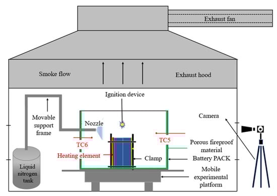
Figure 1.
Test platform.
The LN2 system comprised a pressurized storage tank, a driving gas cylinder, delivery pipelines, and interchangeable spray nozzles. The nitrogen injection pressure was maintained at 2.5 MPa, the flow rate at 10 L/min, and the total injected LN2 mass at 20.25 kg. The spray nozzle was positioned approximately 100 mm from the cell surface, ensuring full coverage.
Six thermocouples were installed on the battery surfaces to record temperature variations, while additional sensors monitored the ambient temperature inside the module. Fumes generated during tests were exhausted through a dedicated fume hood above the container. The entire process was video-recorded for post-analysis.
2.3. Test Protocol
Each test involved two adjacent 70 Ah LiFePO4 cells (denoted as Cell #1 and Cell #2). Cell #1 was heated directly by the 800 W heating plate [19], while Cell #2 represented the adjacent cell potentially exposed to thermal propagation. Thermocouples placed on the front, back, and sides of each battery, labeled TC1, TC2, TC3, TC4, TC7, and TC8, respectively. Furthermore, two additional thermocouples were placed on the top and bottom of the module to record the ambient temperature, as illustrated in Figure 2.
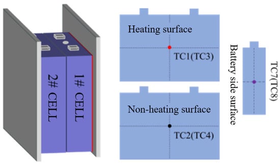
Figure 2.
Battery and thermocouple arrangement.
The heating process began at t = 0 s, and the heating plate was deactivated immediately once the safety valve of Cell #1 vented. Ignition was triggered by an electric spark igniter, simulating a realistic flame initiation scenario. LN2 injection commenced immediately after flame appearance, and LN2 discharge occurred approximately 2 s after actuation due to system response delay.
Ten test conditions were designed to investigate the effects of nozzle diameter and injection strategy, as displayed in Table 1. Conditions 1–6 involved continuous LN2 injection using nozzles with diameters ranging from 6 mm to 16 mm. Conditions 7–10 employed an intermittent injection strategy. The total nitrogen injection volume was 20.25 kg, which was divided into five injections, with an average injection volume of 4.05 kg per injection. The intervals between each injection were 15 s, 30 s, 45 s, and 60 s.

Table 1.
Experimental conditions for LN2 fire-suppression efficiency.
For the conditions set in this paper, more than three repeated experiments were conducted, and the set that was closest to the average value was selected for analysis and research.
3. Results
3.1. Thermal Runaway Characteristics of Lithium Iron Phosphate Battery Packs
Based on the observations under Condition 0, the thermal runaway process of the lithium-ion battery pack in the energy storage module can be divided into four distinct stages: (1) the heating stage, (2) the initial pressure relief stage, (3) the complete thermal runaway stage, and (4) the fire decay stage. As the heating duration increased, the surface temperature of the battery pack gradually rose, resulting in heat accumulation within the cells and the onset of internal chemical reactions. These reactions included the melting of the solid electrolyte interphase film, reactions between the negative electrode and the electrolyte, and reactions between the positive electrode and the electrolyte. The combined effects of these exothermic reactions produced a substantial amount of heat and gas, leading to expansion and deformation of the cells.
Figure 3 and Figure 4, respectively, present the visual evolution of the thermal runaway process and the corresponding surface temperature variations of the lithium-ion battery pack. At 1856 s, the pressure relief valve of Cell #1 began to vent slightly, causing a brief temperature drop before the temperature rose again. At 3306 s, the valve of Cell #1 fully opened, releasing a large volume of flammable gas and electrolyte, followed by intense combustion and significant heat release, with the surface temperature reaching 152 °C. Shortly afterward, at 3309 s, the valve of Cell #2 opened, releasing combustible gases that intensified the flame. Due to oxygen depletion inside the module, the fire quickly subsided. The surface temperature of Cell #2 dropped rapidly to 116 °C at 3323 s and then rose again to 354 °C before gradually decreasing. Subsequently, as openings formed in the module, combustible gases escaped while fresh air entered, reigniting the combustion. The flame intensified again, reaching a peak temperature of 828 °C at the top of the module before stabilizing. At 3592 s, the concentration of combustible gases decreased, and the fire began to extinguish. Complete extinction occurred at 3610 s, marking the end of heat generation in the thermal runaway battery. Thereafter, the surface temperature gradually returned to ambient conditions.
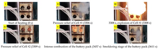
Figure 3.
Experimental observations of thermal runaway of a lithium-ion battery pack.
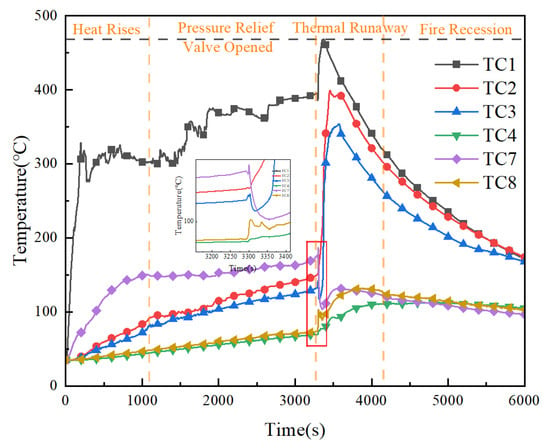
Figure 4.
Surface temperature variations during thermal runaway of battery pack.
To verify the effectiveness of LN2 suppression, a dedicated extinguishing test was conducted as illustrated in Figure 5. As heating progressed, the surface temperature of the heated cell gradually increased until it reached the critical threshold for thermal runaway. At 1563 s, the pressure relief valve of Cell #1 fully opened, releasing a large volume of high-temperature flammable gases and electrolyte vapor. These gases were subsequently ignited by an electric spark, producing an open flame that rapidly intensified. Liquid nitrogen injection into the battery pack commenced at 1632 s, and the visible flame was extinguished within 5 s. The combustible vapors generated during the thermal runaway were entrained by the low-temperature nitrogen vapor produced through LN2 vaporization and vented through the exhaust outlets. As the injection continued, the lower section of the test chamber became filled with dense, cold nitrogen gas. The large amount of moisture condensed from the surrounding air formed a thick frost layer on the LN2 pipelines and the chamber walls. After the nitrogen injection ceased, the ambient temperature within the chamber gradually returned to room conditions. Due to the timely application of LN2, Cell #2 experienced only minor deformation and did not undergo complete thermal runaway.
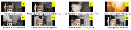
Figure 5.
Sequential stages of liquid nitrogen fire-suppression in the lithium-ion battery pack.
3.2. Analysis of the Influence of Nozzle Diameter on Liquid Nitrogen Fire Extinguishing Efficiency
The light-blue regions in Figure 6a–f indicate the time intervals during which the fire-extinguishing agent was applied. It is evident that, under all six conditions, the maximum surface temperatures of the battery cells were significantly reduced compared with the baseline case without LN2 injection. For Cell #1, the maximum surface temperatures under Conditions 1–6 were 263 °C, 261 °C, 295 °C, 289 °C, 312 °C, and 355 °C, corresponding to reductions of 136 °C, 138 °C, 104 °C, 110 °C, 87 °C, and 44 °C, respectively, relative to the blank control. Similarly, for Cell #2, the maximum surface temperatures were 214 °C, 208 °C, 239 °C, 188 °C, 221 °C, and 283 °C, representing temperature reductions of 139 °C, 145 °C, 114 °C, 165 °C, 132 °C, and 70 °C, respectively. These results demonstrate that the introduction of LN2 effectively suppresses flame development, rapidly extinguishing the fire before it reaches peak intensity. Consequently, the surface temperature of both cells remains substantially lower than in the uncontrolled condition. However, with increasing nozzle diameter, the cooling effect exhibits a nonlinear trend, i.e., initially improving and then declining. This behavior indicates that an optimal nozzle diameter exists, at which the cooling and extinguishing efficiency of liquid nitrogen reach their maximum.

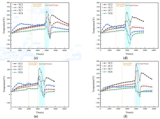
Figure 6.
Surface temperature variation trends of battery pack under conditions 1–6. (a) 6 mm. (b) 8 mm. (c) 10 mm. (d) 12 mm. (e) 14 mm. (f) 16 mm.
Figure 7a illustrates the maximum temperature drop and maximum temperature drop rate of Cell #1 during LN2 exposure. The results indicate that the maximum temperature drop on the cell surface initially increases and then decreases with the enlargement of the nozzle diameter. This behavior suggests that for a fixed total amount of LN2, the temperature drop performance first improves and subsequently deteriorates as the nozzle diameter increases. Condition 5 achieved the largest temperature reduction, while Condition 6 yielded a slightly lower drop than Condition 5 but still notably higher than those in the first four conditions. This trend can be attributed to the variation in LN2 flow velocity. As the nozzle diameter increases, the jet velocity decreases, prolonging the interaction time between LN2 and the battery surface and thereby enhancing the overall heat transfer. However, when the nozzle becomes excessively large, the instantaneous impingement intensity decreases, slightly reducing the temperature drop efficiency. The maximum temperature drop rate of Cell #1 exhibits the opposite trend—it first decreases and then increases with nozzle diameter. This is because, with a larger outlet area, the instantaneous LN2 flow velocity and the amount of coolant directly striking the surface both decrease, leading to a lower initial temperature drop rate.
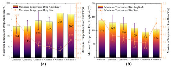
Figure 7.
Variation in maximum temperature drop and temperature rise rates and amplitudes of Cell 1# under continuous injection condition: (a) Variation in maximum temperature drop rate and amplitude of Cell #1. (b) Variation in maximum temperature rise rate and amplitude of Cell #1.
Figure 7b presents the maximum temperature rise amplitude and temperature rise rate of Cell #1 after LN2 injection ceased. The data show that both parameters first decrease and then increase as the nozzle diameter increases. Condition 5 again produced the smallest temperature rise and the lowest temperature rise rate among all cases, while Condition 6 was slightly higher but still below the values observed in the other four conditions. This behavior confirms that Condition 5 provided the highest temperature drop efficiency, the largest temperature drop, and the most effective heat exchange between LN2 and the battery. Consequently, the temperature rise effect after LN2 application was minimized under this condition.
In summary, for a fixed amount of liquid nitrogen, the fire-suppression efficiency against lithium iron phosphate battery packs initially increases and then decreases with increasing nozzle diameter, indicating the existence of an optimal diameter that maximizes suppression performance.
3.3. Analysis of the Influence of Injection Strategy on Liquid Nitrogen Fire-Extinguishing Efficiency
Figure 8 presents the surface temperature evolution of the battery pack under Conditions 7–10. Compared with Condition 5 (continuous LN2 injection of 20.25 kg), the maximum surface temperatures of Cell #1 decreased under all four intermittent injection strategies. Specifically, the peak surface temperatures reached 299 °C, 274 °C, 293 °C, and 311 °C, corresponding to reductions of 12 °C, 37 °C, 18 °C, and 0 °C, respectively, relative to the baseline (Condition 0). In contrast, the maximum surface temperatures of Cell #2 increased slightly compared with Condition 5, reaching 242 °C, 241 °C, 245 °C, and 234 °C, respectively, which represent increases of 21 °C, 20 °C, 24 °C, and 13 °C relative to Condition 0. These results can be attributed to the longer overall duration of LN2 discharge, which promotes more effective heat exchange between the cryogenic agent and the thermal runaway cell. As a result, the temperature of Cell #1 remained lower than that under continuous injection (Condition 5). However, the total duration of LN2 injection also includes the intermittent pauses, during which no cooling occurs. Consequently, heat transfer between adjacent cells continues during these intervals, leading to slightly higher temperatures in Cell #2 compared with Condition 5.
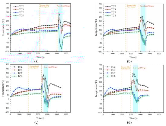
Figure 8.
Surface temperature variation of battery pack during experiment under conditions 7–10. (a) Intermittent (pause duration: 15 s). (b) Intermittent (pause duration: 30 s). (c) Intermittent (pause duration: 45 s). (d) Intermittent (pause duration: 60 s).
During the experiments, Cell #1 underwent severe thermal runaway. After LN2 injection ceased, the maximum surface temperature of Cell #1 in all conditions except Condition 9 exceeded the critical thermal runaway threshold, indicating a high risk of reignition. Under Condition 9, however, the maximum surface temperature of Cell #1 remained below the critical limit, suggesting a low risk of reignition. For Cell #2, mild thermal runaway occurred under all conditions except Condition 9, but in each case, the subsequent LN2 cooling successfully suppressed propagation. After LN2 discharge, the maximum temperatures of Cell #2 remained below the critical threshold, confirming that no reignition occurred under any of the tested intermittent strategies.
Figure 9a illustrates the variations in maximum temperature drop amplitude and temperature drop rate of Cell #1 under the four intermittent injection conditions. The results show that both parameters first increase and then decrease with longer intermittent durations. This trend indicates that the fire-suppression effectiveness of LN2 initially improves as the pause interval increases but deteriorates once the interval becomes excessive. When the intermittent time reached 60 s, both the maximum temperature drop amplitude and maximum temperature drop rate were the lowest among the four conditions, confirming that the suppression capability of LN2 diminishes when the pause exceeds a critical duration.
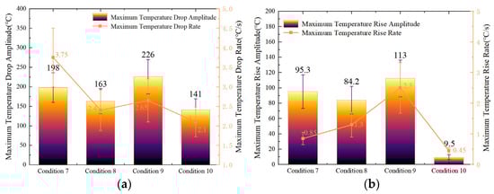
Figure 9.
Variation in maximum temperature drop and temperature rise rates and amplitudes of Cell #1 under the four intermittent injection conditions: (a) Variation in maximum temperature drop rate and amplitude of Cell #1. (b) Variation in maximum temperature rise rate and amplitude of Cell #1.
Figure 9b presents the post-injection maximum temperature rise amplitude and maximum temperature rise rate of Cell #1 under the same conditions. Both parameters first increase and then decrease after LN2 injection ceased. This phenomenon corresponds directly to the cooling behavior observed during injection: as the surface temperature reduction during LN2 spraying first grows and then declines, the subsequent temperature rise amplitude behaves inversely. Consequently, in Condition 9 (45 s intermittent time), the cell surface exhibited the lowest post-injection temperature and, hence, the smallest overall temperature rise. These results demonstrate that a 45 s intermittent injection strategy provides the optimal balance between cooling efficiency and suppression stability under the present experimental conditions.
4. Discussion
4.1. Analysis of Heat Generation and Release During Thermal Runaway of Lithium Iron Phosphate Batteries
In order to quantitatively analyze the heat generation and dissipation process of lithium battery thermal runaway, an energy balance was established based on the law of conservation of energy [20]. The total heat released by a battery during thermal runaway can be expressed as:
The heat transfer path between the two batteries includes heat conduction through the battery casing and heat radiation from the flame. However, according to the research of Feng et al. [8], the heat transfer caused by the flame is very small and has little impact on the thermal runaway propagation process. Therefore, this experiment only considers heat conduction. The heat transfer between the two batteries can be calculated using the following equation:
where q is the heat flow from the geometric center of the first battery to the geometric center of the second battery, and T1 and T2 are the average temperatures of the batteries. is the total thermal resistance between the two batteries, W/K, and the thermal resistance can be calculated by the following formula. Where is the thermal conductivity; where the thermal conductivity of the battery is 0.5 (Zhang et al. [12]); is the heat conduction distance, which is 0.039 m, and is the area through which the heat flow passes, which is the surface area of the contact surface between the two batteries; its value is 0.0155 m2. Since the batteries are closely arranged, the penetration of the extinguishing agent between the batteries is very limited, so this study does not consider the effect of the extinguishing agent penetration on the total thermal resistance. t1 and t2 are the times when the first and second batteries experience thermal runaway, respectively.
The energy stored inside the battery after thermal runaway can be expressed by Formula (6). Where c = 1.1 J/(g·°C) is the specific heat capacity of the battery, and is the residual mass of the battery after thermal runaway. In this study, the average mass loss of the battery after thermal runaway was 18.9%. Tt1 and Tt2 are the temperatures of the thermal runaway battery at t1 and t2, °C.
After the experiment begins, the thermal runaway battery generates a large amount of heat within a short period, causing the battery temperature to rise to its maximum value. Ignoring heat dissipation during this process, the self-generated heat of the battery can be obtained using Formula (7), where is the highest temperature at which thermal runaway occurs, °C. is the initial average temperature of thermal runaway, °C, and m is the battery mass, g. is related to the mass loss during thermal runaway and can be calculated using Formula (8).
Condition 0 is used as an example for calculation. The mass change of the battery pack before and after thermal runaway is shown in Table 2.
Table 2.
Mass parameters of the battery pack before and after thermal runaway for Condition 0.
Based on the above relationships, the total self-generated heat of Cell #1 during thermal runaway was calculated to be approximately 357.8 kJ. Among this total, (a) 67.65 kJ was carried away by the high-temperature vent gases, (b) 24 kJ was stored within the battery itself, (c) 248 kJ was transferred to the adjacent Cell #2, and (d) 18.15 kJ was lost to the surrounding air and environment. As presented in Figure 10, the heat transferred to the neighboring cell accounted for 69% of the total heat generated by Cell #1, confirming the significant risk of thermal runaway propagation in lithium-ion battery systems.
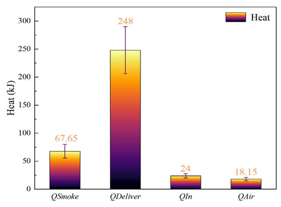
Figure 10.
Heat calculation results of Cell 1# for Condition 0.
Moreover, by the time the first cell entered thermal runaway, the adjacent cell had already undergone a considerable preheating phase. This prior heating substantially shortened the interval between the onset of runaway in the two cells. The high-temperature environment created by the first cell thus accelerated the initiation of thermal runaway in the second, emphasizing the cascading nature of this failure mechanism. The heat transferred to Cell #2 accounted for 69% of the total heat generated by Cell #1, further demonstrating the significant risk of thermal runaway propagation in lithium batteries. Furthermore, by the time the first battery experienced thermal runaway, the adjacent batteries had already experienced a significant heating period, resulting in a decreasing interval between the two batteries’ thermal runaway episodes. Furthermore, the high temperature environment created by the first battery’s thermal runaway accelerated the onset of thermal runaway in the second.
4.2. Analysis of the Influence of Nozzle Diameter on Liquid Nitrogen Cooling Efficiency
To further evaluate the cooling performance of liquid nitrogen (LN2) under different nozzle diameters, the heat absorption during thermal runaway suppression was analyzed for six operating conditions. During the thermal runaway of a battery, the directly heated cell releases a total amount of heat , originating from internal electrochemical reactions and short-circuit processes. A portion of this heat is removed by the extinguishing agent and air exchange (), while another portion is transferred to adjacent cells due to the temperature gradient (). In addition, part of the heat is carried away by the vented smoke and gases (), and the remaining fraction is retained within the cell (). According to the law of conservation of energy, the overall heat balance during thermal runaway can be expressed as:
The cooling efficiency of the extinguishing agent, denoted as , is defined as the ratio of the heat absorbed by the extinguishing agent to the total heat generated by the battery, which can be expressed as:
Table 3 summarizes the results of the six test conditions. As the nozzle diameter increases, the LN2 cooling efficiency first rises and then declines. Condition 4 achieved the highest cooling efficiency of 42%, while Condition 1 exhibited the lowest at 13%. Although Condition 5 was not the highest, its efficiency (40%) was only 2% lower than that of Condition 4, indicating comparable performance.
Table 3.
Thermal data of thermal runaway batteries under six conditions.
As the nozzle diameter increased, the heat transferred between cells first decreased and then increased, whereas the heat removed by LN2 first increased and then decreased. Among all tests, Condition 5 removed the largest amount of heat, while Condition 1 removed the least. Although Condition 6 extracted slightly less heat than Condition 5, its cooling capacity still exceeded that of the smaller nozzles. These results demonstrate that larger nozzles substantially outperform smaller ones in cooling and suppression efficiency. However, beyond a certain size, excessive nozzle diameter reduces jet velocity and heat exchange intensity, leading to diminished performance. Therefore, after comprehensively considering the liquid nitrogen cooling efficiency and the maximum temperature drop aptitude, the optimal nozzle diameter was determined to be approximately 14 mm.
4.3. Analysis of the Influence of Injection Strategy on Liquid Nitrogen Cooling Efficiency
To further examine the effect of different LN2 injection strategies on the cooling performance of thermal runaway battery packs [21], the corresponding heat transfer data under four intermittent conditions are summarized in Table 4. The results show that the cooling efficiency of LN2 first increases and then decreases with longer intermittent durations. Condition 9 achieved the highest cooling efficiency of 63%, whereas Condition 10 showed the lowest at 52%. Although Condition 8 did not reach the maximum, its efficiency (60%) was only 3% lower than that of Condition 9.
Table 4.
Key thermal parameters during the experiment.
Overall, the cooling efficiencies of LN2 under all four intermittent conditions were higher than that of Condition 5 (continuous injection) by 15%, 20%, 23%, and 12%, respectively. Meanwhile, compared with Condition 5, the proportion of heat transferred between adjacent cells decreased substantially by 15%, 19%, 23%, and 14%, respectively. These results clearly demonstrate that intermittent injection significantly enhances LN2 fire-suppression performance relative to continuous injection.
This improvement can be attributed to the prolonged effective cooling time associated with intermittent release. By maintaining a longer residence time of LN2 vapor around the battery surfaces, intermittent injection enables more efficient heat exchange between the cryogenic agent and the thermal runaway cells while simultaneously reducing inter-cell heat transfer and the likelihood of thermal propagation.
5. Conclusions
This study experimentally investigated the effects of nozzle diameter and injection strategy on the fire-suppression and cooling performance of liquid nitrogen (LN2) in mitigating thermal runaway of lithium iron phosphate battery modules. The following major conclusions can be drawn:
- (a)
- The cooling and fire-suppression efficiency of LN2 exhibited a nonlinear relationship with nozzle diameter. Under constant injection pressure, enlarging the nozzle improved cooling efficiency up to a critical point, after which, further increases reduced performance due to the decline in jet velocity and local impingement intensity. The overall suppression efficiency followed an increase-then-decrease trend, confirming the existence of an optimal nozzle size. Under the tested conditions, the 14 mm nozzle achieved the highest cooling efficiency of 40%, approximately 27% higher than the minimum value. Although the cooling efficiency of the 12 mm nozzle is slightly higher than that of the 14 mm nozzle, the maximum temperature drop aptitude of the 14 mm nozzle is approximately 24% higher than that of the 12 mm nozzle. Considering all factors, 14 mm is considered the optimal configuration for liquid nitrogen injection.
- (b)
- Intermittent LN2 injection significantly enhanced cooling performance compared with continuous injection at equal total mass. The cooling efficiencies under four intermittent conditions exceeded that of continuous injection by 15–23%, with the most effective case—Condition 9 (4.05 kg–45 s–4.05 kg)—achieving a 63% cooling efficiency. This improvement results from extended effective cooling duration, enhanced heat exchange, and reduced inter-cell heat transfer, which collectively suppress thermal propagation more effectively. An optimal intermittent duration of approximately 45 s was identified within the tested range.
- (c)
- The results highlight that both geometric optimization (nozzle diameter) and temporal control (injection strategy) are key parameters governing LN2 fire-suppression efficiency in battery energy storage systems. Implementing optimized LN2 delivery—combining an appropriately sized nozzle with an intermittent injection strategy—can markedly improve thermal control and prevent cascade failure in large-scale lithium-ion battery installations. These findings provide a quantitative foundation for the design of next-generation cryogenic fire-suppression systems in practical engineering applications.
Limitations and uncertainties in this study are as follows. The tests were conducted under controlled conditions, and thus, the results may not fully capture the complexities of real-world applications, such as variations in battery aging, state of charge, and environmental factors. In addition, the onset of thermal runaway in lithium-ion batteries is inherently stochastic, leading to variations in the exact timing of liquid nitrogen injection across tests, which may in turn influence suppression efficiency and the consistency of the outcomes.
Author Contributions
B.J.: writing—original draft, project administration, and resources. Z.C.: software, data curation. P.Z.: writing—review and editing, methodology, funding acquisition. B.L.: writing—review and editing, investigation. H.W.: visualization, validation. All authors have read and agreed to the published version of the manuscript.
Funding
Supported by the State Grid Hebei Electric Power Company Technology Project (Grant No. kj2024-028).
Data Availability Statement
The data that support the findings of this study are available from the corresponding author upon reasonable request.
Conflicts of Interest
Authors Boyan Jia, Ziwen Cai, Peng Zhang and Bingyu Li were employed by the company State Grid Hebei Electric Power Research Institute. The remaining author declares that the research was conducted in the absence of any commercial or financial relationships that could be construed as a potential conflict of interest.
References
- Bernardi, D.; Pawlikowski, E.; Newman, J. A General Energy Balance for Battery Systems. J. Electrochem. Soc. 1985, 132, 5–12. [Google Scholar] [CrossRef]
- Zhao, Y.; Kong, J.; Cao, Y.; Liu, H.; You, W. Mapping the Evolution of New Energy Vehicle Fire Risk Research: A Comprehensive Bibliometric Analysis. Fire 2025, 8, 395. [Google Scholar] [CrossRef]
- Spotnitz, R.; Franklin, J. Abuse Behavior of High-Power Li-Ion Cells. J. Power Sources 2003, 113, 81–100. [Google Scholar] [CrossRef]
- Doughty, D.H.; Roth, E.P. A General Discussion of Li-Ion Safety. Electrochem. Soc. Interface 2012, 21, 37–44. [Google Scholar] [CrossRef]
- Golubkov, A.W.; Fuchs, D.; Wagner, J.; Wiltsche, H.; Stangl, C.; Fauler, G.; Voitic, G.; Thaler, A.; Hacker, V. Thermal Runaway Experiments on Li-Ion Cells. RSC Adv. 2014, 4, 3633–3642. [Google Scholar] [CrossRef]
- Wang, Q.; Mao, B.; Stoliarov, S.I.; Sun, J. Thermal Runaway of Li-Ion Batteries: Causes, Prevention, and Mitigation. Prog. Energy Combust. Sci. 2019, 73, 95–131. [Google Scholar] [CrossRef]
- Larsson, F.; Andersson, P.; Blomqvist, P.; Mellander, B.E. Toxic Fluoride Gas Emissions from Li-Ion Battery Fires. Sci. Rep. 2017, 7, 10018. [Google Scholar] [CrossRef] [PubMed]
- Feng, X.; Ouyang, M.; Liu, X.; Lu, L.; Xia, Y.; He, X. Thermal Runaway Mechanism of Li-Ion Batteries for EVs. Energy Storage Mater. 2018, 10, 246–267. [Google Scholar] [CrossRef]
- Di Liberto, E.; Borchiellini, R.; Fruhwirt, D.; Papurello, D. A Review of Safety Measures in Battery Electric Buses. Fire 2025, 8, 159. [Google Scholar] [CrossRef]
- Cao, Y.; Wang, K.; Wang, Z.; Wang, J.; Yang, Y.; Xu, X. Liquid Nitrogen as Efficient Inhibitor for Thermal Runaway. Renew. Energy 2023, 206, 1097–1105. [Google Scholar] [CrossRef]
- Sun, Y.; Zhang, G.; Jia, B. Experimental study on the effect of liquid nitrogen on fire and explosion suppression of high temperature lithium-ion batteries. In Proceedings of the 2020 Annual Conference on Science and Technology of China Fire Protection Association, Zhengzhou, China, 28–29 September 2020; pp. 945–951. [Google Scholar]
- Zhang, X.; Zhang, K.; Wang, H.; Cai, W.; Du, T.; Zhang, A.; Wang, W.; Yu, G. Technical research on fire protection system for lithium battery based on liquid nitrogen fire extinguishing. Electr. Supply Use 2021, 38, 32–39. [Google Scholar] [CrossRef]
- Jia, Z.; Wang, S.; Qin, P.; Li, C.; Song, L.; Cheng, Z.; Jin, K.; Sun, J.; Wang, Q. Comparative Investigation of the Thermal Runaway and Gas Venting Behaviors of Large-Format LiFePO4 Batteries Caused by Overcharging and Overheating. J. Energy Storage 2023, 61, 106791. [Google Scholar] [CrossRef]
- Han, L.; Wang, Z.; He, X.; He, C.; Shi, X.; Yao, B. The effect of water mist strategies on thermal runaway fire suppression of large-capacity NCM lithium-ion battery. Energy Storage Sci. Technol. 2023, 12, 1664–1674. [Google Scholar] [CrossRef]
- Ping, P.; Gao, X.; Kong, D.; Gao, W.; Feng, K.; Yang, C. Experimental study on the synergistic strategy of liquid nitrogen and water mist for fire extinguishing and cooling of lithium-ion batteries. Process Saf. Environ. Prot. 2024, 188, 713–725. [Google Scholar] [CrossRef]
- Zhang, L.; Duan, Q.L.; Meng, X.D.; Jin, K.Q.; Xu, J.J.; Sun, J.H.; Wang, Q.S. Experimental Investigation on Intermittent Spray Cooling and Toxic Hazards of Lithium-Ion Battery Thermal Runaway. Energy Convers. Manag. 2022, 252, 115091. [Google Scholar] [CrossRef]
- Liu, J.L.; Huang, Z.H.; Sun, J.H.; Wang, Q.S. Heat Generation and Thermal Runaway of Lithium-Ion Battery Induced by Slight Overcharging Cycling. J. Power Sources 2022, 526, 231136. [Google Scholar] [CrossRef]
- Shelke, A.V.; Buston, J.E.H.; Gill, J.; Howard, D.; Williams, R.C.E.; Read, E.; Abaza, A.; Cooper, B.; Richards, P.; Wen, J.X. Combined Numerical and Experimental Studies of 21700 Lithium-Ion Battery Thermal Runaway Induced by Different Thermal Abuse. Int. J. Heat Mass Transf. 2021, 179, 121695. [Google Scholar] [CrossRef]
- Xiao, X.; Chen, B.; Jin, X.; Zeng, Q.; Tian, Y.; Li, Q. Experimental Study on the Effect of Synergistic Extinguishing Method Based on Liquid Nitrogen on Lithium-Ion Battery Fire After Thermal Runaway. Fire 2024, 7, 479. [Google Scholar] [CrossRef]
- UL 9540A; Test Method for Evaluating Thermal Runaway Fire Propagation in ESS. UL Standards: Northbrook, IL, USA, 2023.
- Kim, S.-J.; Yu, Y.-S.; Jeong, C.-S.; Lee, S.-B.; Na, Y.-U. Thermal Runaway Propagation in Pouch-Type Lithium-Ion Battery Modules: Effects of State of Charge and Initiation Location. Batteries 2025, 11, 398. [Google Scholar] [CrossRef]
Disclaimer/Publisher’s Note: The statements, opinions and data contained in all publications are solely those of the individual author(s) and contributor(s) and not of MDPI and/or the editor(s). MDPI and/or the editor(s) disclaim responsibility for any injury to people or property resulting from any ideas, methods, instructions or products referred to in the content. |
© 2026 by the authors. Licensee MDPI, Basel, Switzerland. This article is an open access article distributed under the terms and conditions of the Creative Commons Attribution (CC BY) license.