Abstract
Many reclaimed areas in Indonesia have abandoned swampland or idle land which is attributed to various factors. One of the main factors is the unsuitability of the exiting flow system in this area since the condition of the canals and water structures in this area has not been rehabilitated for a long time. No study has been carried out to investigate the suitable model for simulating the appropriate criteria for assessment of erosion within the channel on Tidal lowland in Indonesia. This study focuses on the investigation of erosion occurring within the Rural Channel and Main Drainage Channel on Tidal lowland in Palembang, Indonesia which becomes the originality of this manuscript. The erosion was attributed to the accumulation of sediment transport within the channel of the reclaimed tidal delta region Telang I. The results of the research on the P8-13S scheme show that equilibrium on the accumulation of sediment transport in the channel was observed in the Rural Channel and Main Drainage Channel on average ranging from 3,301,859 m3 to 3,349,103 m3 while the average sedimentation ranged from 809,232–898,467 m3. This study is very important in minimizing the possible erosion near riverbank.
1. Introduction
Sediment transport is critical for all aquatic habitats, but particularly lagoons, where the volume and direction of suspended matter has a direct effect on the turbidity of the water [1,2,3]. It has the potential to alter primary production and other ecological processes within a system [4]. Sediments play a critical role in sculpting the terrain where rivers meet the sea. Inadequate sedimentation to the sea may result in coastal erosion, leading in the loss of land and tidal wetlands, necessitating coast protection and saltmarsh or beach nourishment methods [5]. Furthermore, human action occasionally modifies the coastline, frequently unintentionally altering previously identified sediment transport channels and coastal morpho dynamics [6]. Juez et al. [7] proposed a model for simplification of coupling technique for modelling transient shallow flow and movable bed to reduce the computational cost and time. Zordan et al. [8] concluded that bed shear stress and Reynolds stresses are correlated with sediment entrainment for longer periods, such that it can be inferred that they are associated to the distal transport of sediment. The main responsible for sediment dislodging is found to be the vertical component of the fluid movement, which presents a high peak of vertical mean velocity at the front of the currents.
Potential land for farming in Indonesia includes around 150 million ha. Some parts are located within swamp area, which cover an area of around 33 million ha. This swamp land is situated within tidal swamp with area of 21 million ha and normal swamp with area of 12 million ha. These swamps land are distributed across the islands of Kalimantan, Sulawesi, Sumatera and Papua, covering an area of about 10 million hectares each [9].
The Indonesian government has reclaimed some of the swamp areas. The reclamation by private sector is around 1.9 million ha while the reclamation by the community is around 2.1 million ha with a total reclamation of 4 million ha [10]. However, only few areas of these reclaimed lands are utilized to generate crops. The productivity of the land is around 3 t/ha which is utilized by the government. A lack of attention to Operations and Maintenance has resulted in a micro-scale repair effort in tertiary channels without a sluicegate structural framework, which means that farmers are doing their own micro-scale maintenance on their own initiative [11].
Based on an inventory study of swamp area data in the western and eastern regions, it is concluded that 0.8 million ha of 1.8 million ha reclaimed area is abandoned swampland or idle land, which is attributed to various factors [12]. One of the main factors is the unsuitability of the exiting flow system in this area since the existing water system network is not optimal. The other important factor is related to the condition of the canals and water structures in this area which has not been rehabilitated for a long time. In addition, the maintenance of the channels is not optimal [13].
The originality of this study is related to the investigation of the suitable model for simulating the appropriate criteria for assessment of erosion within the channel on Tidal lowland in Indonesia. The criteria to determine the stability within the channel is related to no erosion and sedimentation observed in the channel with the equilibrium condition of the channel. Although erosion and sedimentation exist, but it should be merely temporary material movements in the channel which does not affect the general condition of the channel. No study has been carried out to investigate the suitable model for simulating the appropriate criteria for assessment of erosion within channel on Tidal lowland in Indonesia. This study focuses on the investigation of erosion occurring within the Rural Channel and Main Drainage Channel on Tidal lowland in Palembang, Indonesia.
2. Site Overview and Methodology
According to this research, the area under investigation is located in Delta Region Telang I in the province of South Sumatra, which is characterized by swampy terrain and little rainfall. With the second generation of the double-grid design layout (Rib System), this region was also reclaimed, along with Telang II, Delta Saleh, and Sugihan, as the second generation [14]. A future open channel system has been designed for the Delta region Telang I [15]. In addition to the main line (which is also used for navigation), the system includes secondary channels and tertiary channels. The site location in this study is depicted in Figure 1 [16].
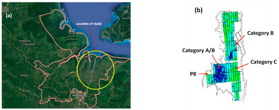
Figure 1.
(a) The investigated location in this study; (b) Layout of the investigated primary channel 8 (P8).
Telang I lies between 020 29 and 020 48′ latitude and 1040 30 and 1040 52′ east longitude, according to GPS. As a result, the country’s northern and southern borders are bounded by the Strait of Bangka and Telang I respectively. In contrast, the eastern region, which includes the river Musi, and the western region, which includes the river Telang I [17].
Telang I is a hydrologically significant location since it is bordered by tidal rivers. The Musi river runs through the eastern section of the territory, while the Telang river runs through the western part of the region. According to the Land and Water Management Tidal Lowlands (LWMTL) [11], the Bangka Strait borders the southern portion of the province, whilst the river borders the northern part of the territory. As a result of these factors and others, hydrology can be affected on a local and global scale by the surrounding channels, the water levels in each channel, the sluicegate’s operation, tides, and other environmental factors.
The numerical studies in this work were carried out using Mike-11 for simulating each prototype of flap-gate based on two-dimensional (2-D) finite element calculations. MIKE-11 mathematical modelling technique was developed in the Danish Hydraulic Institute. The MIKE11 software (Version 2009, Danish Hydraulic Institute, Kopenhagen, Denmark) is based on an implicit finite difference scheme solution of the Saint Venant equations [18]. Equations (1) and (2) are used for hydrodynamic model simulated by the software.
where A the flow area, b is the width of channel, h is the stage, Q is the discharge, R is the hydraulic radius, n is the roughness coefficient, β is the momentum distribution coefficient, q is the lateral inflow rate per unit length.
3. Numerical Analyses Results and Discussions
Research on channel stability has been carried out under various scenarios to determine a suitable pattern for channels in tidal swamp areas. The stable criterion is that there is no erosion or sedimentation in the channel with equilibrium channel conditions. Although erosion and sedimentation occur, it is only a momentary material transfer to the channel without affecting the condition of the channel in general.
Tidal swamps in the delta Telang I where the study was conducted consists of a 26,680 ha of reclamation area. This area was opened in 1976 and it was developed as transmigration area for people from Java which began in the early 1980s [19]. In the development stage, this area was built with a water system and supporting infrastructure for the development of tidal swamp farming business [20].
The length of the primary channel P8-13S is 19,071 m. The secondary channel is divided into two: Rural Channels (RC) and the Drainage Channel or Main Drainage Channel (MDC) which is located on the boundary of the business area II. The length of the RC secondary channel is 3267 m and MDC is 3807 m. the area of one secondary block is 256 hectares.
The water system in this area works based on the concept of a one-way flow system where tidal water flows into the RC and then it is released through the MDC. At present, the RC and MDC both have functions as water intake and drainage channels. This one-way water management system will provide good prospects if it is equipped with water gates (flap-gate, stop-log or block) as a water regulator that can be controlled (Noor, 2004).
On the secondary channel P8-13S, a survey was carried out on the longitudinal and transverse directions based on topographic and water level measurements. Most of the tertiary canals in P8 are still unmodified, only certain part of this area has been modified including the Southern part of the area with 13 secondary block (P8-13S). In general one secondary block has the same area of ±256 ha with a total of 17 tertiary canals channel bar (Figure 2).
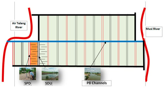
Figure 2.
Schematic diagram of water system at P8 Telang I.
Many tertiary channels in P8 are not connected into the RC. There are only a small number of channels that penetrate to the RC. Almost all of channels penetrate to the secondary Main Drainage Channel (MDC). All secondary channels, both RC and MDC in line P8 initially were not supported by water control structures. Only until 2010, four sluice-gates were built in SDU 13-S secondary channels and 5 are in RC13-South.
3.1. P8-13S Channel Hydraulic Model Analysis and Simulation
Simulations of morphological changes in both Primary 8 (P8) channels and SPD and SDU secondary channels, were performed using MIKE-11 2D software [18]. The initial condition in the numerical simulation was determined based on the elevation of the water level in the RC and MDC channels in P8-13S. The elevation of the water level in the Rural Channel was recorded for 24 h starting from 8:00 am in the morning until 8:00 am in the next day [21]. The elevation of the water level in the channel was −0.20 m recorded at 08:00 am and the elevation of the peak water level was 1.60 m recorded at 13.00 pm. Then the elevation of the water level decreased to the minimum value of −0.61 m at 03:00 am in the following morning. (Figure 3).
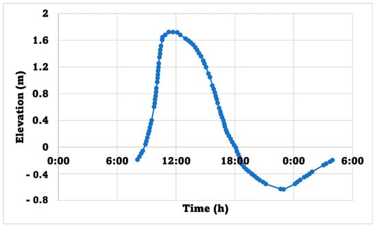
Figure 3.
Water level elevation in the Rural Channel.
Likewise, the elevation of the water level in the SDU channel was recorded for 24 h starting from 08:00 am in the morning until 08:00 am in the next day. The level of water level in the channel was −0.28 m at 08:00 am and the elevation of the peak water level was 1.63 m at 13.00 pm. Then the water level decreased to the minimum value of −0.50 m at 3:00 am in the next morning. A boundary condition in the numerical simulation was determined based on the water level in the mouth of the P-8 channel. The water level in the mouth of the P8 channel was recorded for 24 h starting at 08:00 am in the morning until 08:00 am in the next day. The elevation of the water level in the channel was 2.80 m at 08.00 am and the peak water elevation was 4.60 m at 13:00 pm. Then the water level decreased to the minimum value of 2.00 m at 3:00 am in the next morning. (Figure 4). Calibration for sediment movement was conducted based on P8 channel parameters. The width of P8 channel is 50 m and the height or depth of this channel is 4.80 m. (Figure 5). All boundary conditions are incorporated in the numerical model. Table 1 presents RC and MDC schemes without sluicegate structure, RC and MDC schemes with sluicegate structure, and RC, MDC schemes and tertiary channels with sluicegate structure [22].
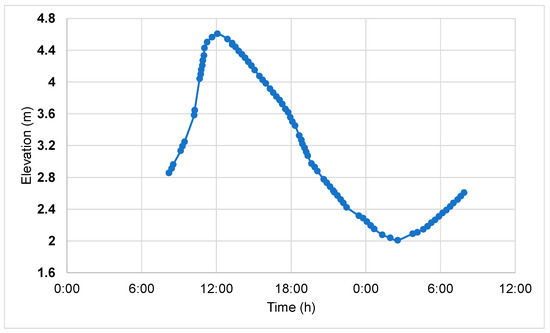
Figure 4.
The water level at the mouth of the P-8 channel.
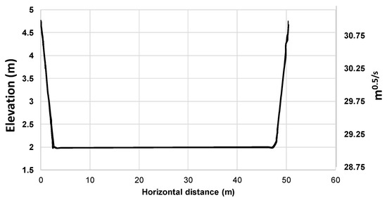
Figure 5.
Sediment transport model simulation results.

Table 1.
Parametric studies carried out in this study.
3.2. Accumulation of Sediment Transport in the Channel
The state of the study region prior to 2012 is presented in Scenario 1. The state of the study area after 2012 is presented in Scenario 2 [23]. This scenario models P8, RC, or MDC without the use of a sluicegate, with the assumption that channel maintenance is not correctly executed. The Manning roughness coefficient (n) is chosen to be 0.025 s/m1/3 in this calculation. The channel in this situation still has grass in it, which indicates that the flow is obstructed, which means that the flow velocity in the channel is decreased [15].
This scenario consists of eight primary channels, one RC channel, one MDC channel, and two tertiary channels. In both the tertiary and secondary channels, sluicegate structures are not available. The function of the channel as a supply or as a sewer cannot be recognized without the use of a sluicegate structure. The water supply routes are used during high tides, and the drainage channels are used during low tides. Figure 6 depicts a network system in the scenario described above [24].
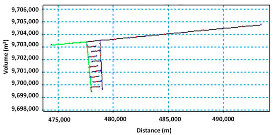
Figure 6.
Schematic diagram of channel models for sediment movement in RC without sluicegate of the scenario I (OM 25%).
A distance of 3200 m from the beginning of the P8 channel is shown in Figure 7 as sediment movement in the RC and the P8 channel. A total of 4,224,089.34 m3 was eroded before the Rural Channel (RC) sedimentation began at 871. As a result, no sediment movement occurred up to a distance of 3650 m from the channel’s end.
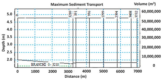
Figure 7.
Sediment movement in RC without flap-gate.
Primary 8 channel and MDC have sluicegate structures that are not present in secondary and tertiary networks. The channel’s ability to serve as either a supply or a sewage cannot be determined without the presence of a sluicegate structure. At high tide, all waterways are water supply routes, while at low tide, all channels are drains. For example, Figure 8 depicts the accumulation of sediment movement that occurs along the P8 channel and MDC without a sluicegate 3200 m downstream of the Telang river erosion, which totaled 4,224,089.33 m3, and 4500 m downstream of the MDC, where no sedimentation had occurred prior to the start of the MDC. Up to a distance of 3650 m, the MDC channel did not have any sediment flow.
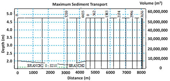
Figure 8.
Sediment movement in MDC without sluicegate.
Due to maintenance, the waterway in Scenario II is in a better condition than in the prior scenario. To put it another way, it is anticipated that there will be no grass along the channel’s path because of its shape. Some of the secondary channels’ cross sections have the same dimensions as those in the tertiary channels. It was decided that in this case the manning coefficient n would be bigger than in scenario I. Manning n is assumed to have a coefficient of 0.033 s/m1/3 in this case. Primary 8 and RC networks are shown schematically in Figure 9. To put it another way, the sluice gate is located in the Rural Channel (RC). At high tide, all waterways are water supply routes, while at low tide, all channels are drains.
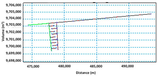
Figure 9.
Schematic diagram of channel models for sediment movement in RC with sluicegate on scenario II (O&M 50%).
A total of 4,360,350.28 m3 of erosion was caused by sediment transport in the P8 channel and Rural Channels (RC) located 3200 m from the P8 channel’s starting. A total of 1,090,087.57 m3 of sediment was deposited at the start of the Rural Channel (RC). The Rural Channel had no sediment movement up to a distance of 3650 m from the channel’s end. A total of 4,496,611.23 m3 of sediment was transported by P8 channel and MDC over a 3200 m distance from the P8 channel’s beginning, according to Figure 10. At a distance of 4500 m, sedimentation happened once more in the P8 channel. Sediment is not moving until the end of the channel, which is 3650 m away from the MDC meeting point in the canal.
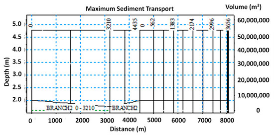
Figure 10.
Sediment movement in MDC is sluicegate.
Compared to scenarios I and II, Scenario III assumes that the channel is well-maintained. As a result, the channel’s shape is based on the original plan, and no new grass is expected to sprout along its length. Both the secondary and tertiary channels have the same cross sectional area. n, the manning coefficient, is higher in this situation than in either scenario I or II [15]. The of coefficient of manning (n) for this scenario is 0.035 s/m1/3.
Figure 11 depicts sediment transit buildup in channels P8, RC, and tertiary channel 1. (tc-1). 3200 m in length from the P8 channel’s inception to its end, 4,360,350.28 cubic meters (m3) of erosion was recorded. Sediment deposition totaled a total of 953,826.62 cubic meters from the beginning of channel RC to the beginning of channel TC-1’s third-generation (a distance of 200 m). The terminus of the tc-1 channel saw sedimentation of 3,470,461.48 m3 from the beginning to a distance of 750 m.
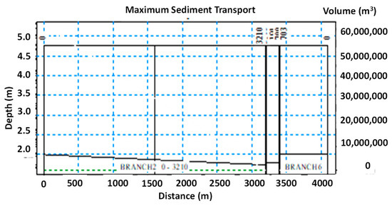
Figure 11.
Movement of sediment in the tc-1 tertiary channel has a sluicegate.
In the RC secondary channel and the tc-3 tertiary channel, sluicegate structures have a roughness coefficient of 0.35. A total of 4,496,611.27 m3 of cumulative erosion occurred over a distance of 3200 m from the P8 channel to the RC channel. A total of 953,826.62 m3 was deposited in the RC channel from its inception to the beginning of the first tc-3 tertiary channel. The terminus of the tc-3 channel experienced sedimentation of 3,222,571.38 m3 from the beginning to a distance of 750 m. Figure 12 is a network system scheme of Primary channel 8 (P8), RC and tertiary channel 5 (tc-5). The RC secondary channel and tc-5 tertiary channel contain the valve door construction, with a roughness coefficient of 0.035 in the channel.
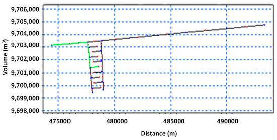
Figure 12.
Cross section of channel models for sediment movement in channels tertiary tc-5 there is a sluicegate.
The P8 channel, the Reverse Channel (RC), and the Tertiary Channel (5, or tc-5) all followed a similar pattern of sediment transport, with a total of 4,496,611.27 m3 of channel erosion occurring over a distance of 3200 m from the beginning of the P8 channel in the Telang river to the beginning of the RC, and then 1800 m from the beginning of the RC to the beginning of the tc-5 tertiary channel. For this construction, the roughness coefficient in the channel is taken to be 0.035. It is placed in the secondary channel and the seventh tertiary channel.
Figure 13 shows that sediment transport occurred in the P8 channel, the RC channel, and the tertiary channel 7 (tc-7), with channel erosion totaling 4,709,912.01 m3 at a distance of 3200 m between the beginning of the P8 channel and the beginning of the RC channel, and sedimentation totaling 867,615.37 m3 between the beginning of the RC channel and the beginning of the tc-7. Figure 13 shows that sediment transport occurred in Between the beginning of the tc-7 channel and the end of the channel, sedimentation totaled 3,222,571.38 m3 and the end of the channel, sedimentation totaled 3,222,571.38 m3. The beginning of the tc-7 channel up to a distance of 750 m and the end of the channel, sedimentation totaled 3,222,571.38 m3. For the sluicegate structure, it is positioned both in the RC secondary channel and in the tc-9 secondary channel, with a roughness coefficient in the channel taken at 0.0355 for the RC secondary channel and 0.0355 for the tc-9 secondary channel.
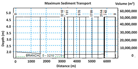
Figure 13.
Sediment movement in the tc-7 tertiary channel has a sluicegate.
4. Conclusions
Based on the three scenarios carried out in the simulation using MIKE-11 2D program, it is observed that Scenario III with a 75% O&M model (RC, MDC and tertiary channels have sluicegate) is considered as the most suitable condition for the P8-13S scheme prototype model. P8 channel erosion occurred with an average volume of 3,599,979.28 m3 while sedimentation occurred in the Rural Channel (RC) with an average volume of 963,836.56 m3. An average tertiary channel erosion amounted to 3,251,972.30 m3. The P8 channel eroded with an average volume of 3,419,184.75 m3 and sedimentation occurred at Main Drainage Channels (MDC) and the tertiary channel was the same value as the magnitude of the erosion at P8 which was an average of 3,419,184.75 m3. The channel conditions in the P8-13S scheme of the Telang I tidal area can be said to have reached an equilibrium.
Author Contributions
A.S. (Alfrendo Satyanaga), A.S. (Achmad Syarifudin), S.-W.M. and J.K. conceptualized the study; A.S. (Alfrendo Satyanaga), A.S. (Achmad Syarifudin) and M.W. implemented data processing under the supervision of S.-W.M. and J.K.; the original draft of the manuscript was written by A.S. (Alfrendo Satyanaga), A.S. (Achmad Syarifudin), S.-W.M. with editorial contributions from M.W. and J.K.; the funding acquisition was made by A.S. (Alfrendo Satyanaga). All authors have read and agreed to the published version of the manuscript.
Funding
This research was funded by the Nazarbayev University Research Fund under Grants 11022021CRP1512 and Social Policy Grant.
Institutional Review Board Statement
Not applicable.
Informed Consent Statement
Not applicable.
Data Availability Statement
All data are available upon request.
Acknowledgments
This research was supported by the Nazarbayev University Research Fund under Grants 11022021CRP1512 and Social Policy Grant. The authors are grateful for this support. Any opinions, findings, and conclusions or recommendations expressed in this material are those of the author(s) and do not necessarily reflect the views of the Nazarbayev University.
Conflicts of Interest
The authors declare that the research was conducted in the absence of any commercial or financial relationships that could be construed as a potential conflict of interest.
References
- Nearing, M.A.; Xie, Y.; Liu, B.; Ye, Y. Natural and anthropogenic rates of soil erosion. Int. Soil Water Conserv. Res. 2017, 5, 77–84. [Google Scholar] [CrossRef]
- Alewell, C.; Borrelli, P.; Meusburger, K.; Panagos, P. Using the USLE: Chances, challenges and limitations of soil erosion modelling. Int. Soil Water Conserv. Res. 2019, 7, 203–225. [Google Scholar] [CrossRef]
- Wang, B.; Zheng, F.; Guan, Y. Improved USLE-K factor prediction: A case study on water erosion areas in China. Int. Soil Water Conserv. Res. 2016, 4, 168–176. [Google Scholar] [CrossRef]
- Satyanaga, A.; Wijaya, M.; Zhai, Q.; Moon, S.-W.; Pu, J.; Kim, J.R. Stability and Consolidation of Sediment Tailings Incorporating Unsaturated Soil Mechanics. Fluids 2021, 6, 423. [Google Scholar] [CrossRef]
- Pu, J.H.; Wallwork, J.T.; Khan, M.A.; Pandey, M.; Pourshahbaz, H.; Satyanaga, A.; Hanmaiahgari, P.R.; Gough, T. Flood Suspended Sediment Transport: Combined Modelling from Dilute to Hyper-concentrated Flow. Water 2021, 13, 379. [Google Scholar] [CrossRef]
- Wallwork, J.T.; Pu, J.H.; Kundu, S.; Hanmaiahgari, P.R.; Pandey, M.; Satyanaga, A.; Khan, M.A. Review of Suspended Sediment Transport Mathematical Modelling and Experimental Studies. Fluid 2022, 7, 23. [Google Scholar] [CrossRef]
- Juez, C.; Murillo, J.; García-Navarro, P. A 2D weakly-coupled and efficient numerical model for transient shallow flow and movable bed. Adv. Water Resour. 2014, 71, 93–109. [Google Scholar] [CrossRef]
- Zordan, J.; Juez, C.; Schleiss, A.J.; Franca, M.J. Entrainment, transport and deposition of sediment by saline gravity currents. Adv. Water Resour. 2018, 115, 17–32. [Google Scholar] [CrossRef]
- Syarifudin, A. The influence of Musi River Sedimentation to The Aquatic Environment. MATEC Web Conf. 2017, 104, 10104026. [Google Scholar] [CrossRef]
- Tallar, R.Y.; Suen, J.P. Aquaculture Water Quality Index: A low-cost index to accelerate aquaculture development in Indonesia. Aquacult. Int. 2016, 24, 295–312. [Google Scholar] [CrossRef]
- Land and Water Management Tidal Lowlands (LWMTL); South Sumatera Province. Operasi dan Pemeliharaan Jaringan dengan Perkumpulan Petani Pemakai Air (P3A); ARCADIS-Euroconsult in Cooperation with Kimpraswil, Department Pertanian, Sriwijaya University and Local Government South Sumatera; Indonesia, Rikjkswaterstaat: Utrecht, The Netherlands; UNESCO-IHE: Paris, France, 2004. [Google Scholar]
- Tallar, R.Y.; Satyanaga, A. Incorporating rainwater-harvesting and retention basins design into urban development paradigms in Greater Bandung, Indonesia. In Water and Urban Development Paradigms; Feyen, B., Shannon, K., Neville, M., Eds.; CRC Press: London, UK, 2008; p. 712. [Google Scholar]
- Syarifudin, A. The Effect of Channel Sedimentation in the Tidal Swamp Area on the Typology of Land A/B Delta Telang I Banyuasin Regency. In Proceedings of the 5th AvoER Proceeding Seminar, Palembang, Indonesia, 28 November 2013. [Google Scholar]
- Houterman, J.; Djoeachir, M.; Robiyanto, H.S.; van Steenbergen, F. Water Resources Management During Transition and Reform in Indonesia Toward an Integrated Perspective on Agricultural Drainage, Agriculture and Rural Development; The International Bank for Reconstruction and Development Agriculture & Rural Development Department: Washington, DC, USA, 2004. [Google Scholar]
- Syarifudin, A.; Momon, S.I.; Arie, S.M.; Yazid, M.; Suryadi, F.X. Erosion on the Secondary Canal of Reclaimed Agriculture Tidal Lowlands Telang I Banyuasin Regency. J. Clean Energy Technol. 2014, 2, 1. [Google Scholar] [CrossRef]
- Euroconsult; Arcadis; Indec & Associates Ltd.; PT. Trans Intra Asia; PT. Necon Ciptajasa; PT. Binatama Wirawredha. Integrated Swamps Development Project IBRD Loan 3755–IND, Final Report O&M Strengthening in ISDP; Republic of Indonesia, Ministry of Settlement and Regional Infrastructure, Directorate General of Rural Development: Jakarta, Indonesia, 2000. [Google Scholar]
- Euroconsult; PT. BIEC International; PT. Trans Intra Asia. Telang and Saleh Agricultural Development Project, Drainage Development Component, O&M Manual; Republic of Indonesia, Ministry of Public Works, Directorate General of Water Resources Development: Jakarta, Indonesia, 1996. [Google Scholar]
- Harsono, E. Prospect of the Development of Swamp Areas in Indonesia; 60 Years of the Department of Public Works: Jakarta, Indonesia, 2005. [Google Scholar]
- Hartoyo, S.; Sumarjo, G.I.; Robiyanto, H.S.; Schult, B.; Suryadi, F.X. Potential and constrains of water management measures for tidal lowlands in South Sumatra. Case study in a pilot area Telang I. In Proceedings of the 9th Inter-Regional Conference on Water Environment, Envirowater, Concept for Water Management and Multifunctional Land Uses in Lowlands, Delft, The Netherlands, 17–19 May 2006. [Google Scholar]
- Danish Hydraulic Institute (DHI). MIKE-11. A Modeling System for Rivers and Channels, User Guide; DHI Software: Kopenhagen, Denmark, 2007; pp. 15–17. [Google Scholar]
- Robiyanto, H.S. Water management technologies on tidal wetlands in Indonesia in a multidimensional perspective. In Proceedings of the National Seminar the Role and Prospects of Development of Wetlands in National Development, Jakarta, Indonesia, 2006. [Google Scholar]
- Syarifudin, A.; Momon, S.I.; Arie, S.M.; Yazid, M.; Suryadi, F.X. Technical Approach of Erosion and Sedimentation on Canal (Case study in Delta Telang I, Banyuasin, South Sumatra Province). In Proceedings of the International Workshop on Sustainable Management of Lowland for Rice Production 2012, Banjarmasin, Indonesia, 27–28 September 2012. [Google Scholar]
- Suprianto, H.; Ravaie, E.; Irianto, S.G.; Susanto, R.H.; Schultz, B.; Suryadi, F.X. Land and water management of tidal lowlands: Experiences in Telang and Saleh, South Sumatra. Irrig. Drain. 2010, 59, 317–335. [Google Scholar]
- Syarifudin, A.; Dewi, S. A Scouring Patterns Around Pillars of Sekanak River Bridge. J. Phys. IOP Conf. Ser. 2019, 1167, 012019. [Google Scholar] [CrossRef]
Publisher’s Note: MDPI stays neutral with regard to jurisdictional claims in published maps and institutional affiliations. |
© 2022 by the authors. Licensee MDPI, Basel, Switzerland. This article is an open access article distributed under the terms and conditions of the Creative Commons Attribution (CC BY) license (https://creativecommons.org/licenses/by/4.0/).