Abstract
The passage of a premixed stoichiometric methane-air flame through a hole in an internal barrier in a Hele-Shaw channel with one end closed was studied experimentally. It was found that for the same initial conditions, a flame propagating from the closed channel end can either pass through the hole in the barrier or be extinguished. The passage probability dependence on the hole width was found to be non-monotonic, with a sharp maximum at small hole sizes, followed by a minimum at intermediate sizes and a gradual increase as the blockage ratio tends to zero. The nature of this non-monotonic behavior of flame passage probability was analyzed by analyzing the flame front histories leading to flame passage or extinction at the same experimental parameters. A likely cause of this behavior is the development of an alternating-direction gas jet blowing from the hole due to the pressure difference between the channel compartments. Cooling of hot combustion products with cold channel walls can cause a pressure drop in the closed channel part and development of a reverse (open-to-closed compartment) gas jet affecting the approaching flame. Therefore, flame passage or extinguishment is a feature of the whole two-chamber system, rather than an intrinsic flame property.
1. Introduction
Flame propagation in complex geometries, featured by strong interaction of the flowfield and combustion zone with obstacles, is of high interest in many engineering applications, including internal combustion engines, combustion chambers, rocket and aircraft engines, to name a few. The obstacles present in the flow can cause significant momentum and heat losses, the development of vortices and recirculation zones, or the transition of laminar flow to turbulent. This interaction can promote the development of flame instabilities, affect the ignition or extinction of combustible mixture, flame propagation speed, etc.
One of the areas where studies of flame interaction with obstacles were performed quite comprehensively was the problem of flame acceleration and deflagration (subsonic combustion) transition to detonation (supersonic combustion). The deflagration to detonation transition (DDT) may occur in various congested areas (domestic gas explosions, accidents at offshore platforms), but also in the open terrain where vegetation and naturally present objects can cause flow turbulization [1,2]. The significant increase in the combustion rate in a turbulent flow, as compared to laminar combustion, is the primary cause of flame acceleration, generation of pressure waves and, in certain conditions, detonation of combustible mixture [3,4].
Numerous experimental studies on DDT caused by obstacles have been performed, typically in long channels with regular or periodic arrays of internal obstacles installed [5,6,7,8]. It has been established that the blockage ratio (BR), defined as the ratio of the obstacle area normal to the flow to the cross section area of the whole channel, plays the key role in flame acceleration in channels with tightly spaced obstacles, affecting the pressure build-up, flame propagation speed, as well as the length at which deflagration to detonation transition occurs [9,10]. Quite sophisticated experimental techniques—from Schlieren imaging [11,12] to OH-PLIF [13]—were applied in order to visualize the flame shape, the development of instabilities, and the flow structure near the obstacle. Also, various numerical techniques were applied to perform simulations of flame acceleration and turbulization by obstacles [14,15]. These revealed the details of the process that are difficult to measure experimentally, such as flame topology and structure, vorticity and local fuel consumption rate.
Another area where flame passage through a small orifice is relevant is the ignition of combustible mixture by hot turbulent jets encountered in the design of combustion chambers and engines. In particular, the concept of pre-chamber-type ignition evolved from seminal theoretical considerations [16,17] into technological implementations for different fuels, including traditional hydrocarbons [18] and hydrogen [19]. It was shown in numerous experiments that critical conditions exist for the ignition, with flame quenching occurring for the orifice diameter below some certain value. In this area, attention is mostly focused on turbulent mixing and reaction initiation in the acceptor chamber, optimization of the pre-chamber volume and orifice diameter, and studying the ignition delay after injection of the hot jet. In particular, the “flame jump” across the orifice was studied, and geometrical and acoustical effects were subjects of experimental and numerical studies [20]. Also, ignition by a turbulent jet formed by combustion products discharged through an orifice can lead to a secondary explosion in the accepting chamber, with severe consequences endangering people and property [21].
The problem of flame interaction with obstacles is not limited to large-scale problems, DDT phenomenon, or explosion safety. In fact, small-scale problems where laminar flames are propagating in complex geometries bear both scientific significance and high applied value. To a large extent, this is related to the development of small devices using combustion: small-scale thrusters, micro-combustors, micro-engines, and other micro electro-mechanical systems (MEMS) [22]. In such devices, flame propagation occurs in close interaction with channel geometry (walls, baffles, bends, orifices, etc.), and this interaction is very pronounced because of the close proximity of walls and large surface-to-volume ratio.
Another closely related problem is flame propagation through a highly congested area; in particular, flame propagation through a small opening in an otherwise impermeable barrier. It is well known that there exists a critical tube diameter below which a flame cannot propagate in a tube filled with combustible mixture [23]. In the classical theory of this phenomenon, critical conditions for flame propagation are attributed to heat losses from the flame directly into the tube walls, as well as to the combustion products behind the flame. The theory assumes that the fresh mixture is stagnant, and the combustion products are flowing freely out of the tube, so that the whole system is isobaric. In practical systems, however, flame penetration through an opening in a barrier is a much more complicated process where the finite length of the passage, pressure drop across the barrier, and non-one-dimensional effects come into play, making the direct application of the critical tube diameter very questionable. Therefore, special studies are required on laminar flame propagation, or quenching, upon passage through a hole in a barrier.
This work is devoted to experimental studies on laminar flame passage over a small hole connecting two compartments filled with combustible mixture. A convenient arrangement for such studies is a planar channel consisting of two parallel plates separated by a narrow gap (the Hele-Shaw cell) [24] that has gained popularity in combustion studies.
Premixed flame propagation in narrow planar channels is the subject of numerous theoretical and experimental studies on flame instability, cellular structure, thermal and concentration combustion limits, and other flame features [25,26,27,28,29,30,31,32]. The quasi-two-dimensional geometry of channel, with one dimension being much smaller than the other two, makes the flame front tracking and cell identification much easier than in transient three-dimensional flames, maintaining a sufficient degree of freedom for complex flame structure development. This allows one not only to track the flame propagation conveniently, but also to develop theoretical and numerical models on flame instability [25,33,34].
Various geometries of Hele-Shaw channels were used in the studies on premixed laminar flame propagation. One of the popular arrangements is a vertical rectangular channel, with the flame initiated near one side to propagate over the channel length (e.g., [26,29]). Effects of channel inclination angle on flame propagation and development of intrinsic instabilities was studied in [30]. Another popular configuration is a horizontal Hele-Shaw chamber formed by two circular disks; propagation of propane-air [27] and hydrogen-air [28] in such chambers was reported in the literature. Also, stoichiometric methane-air and methane-hydrogen-air flames propagating in the diverging Hele-Shaw channels were studied experimentally and theoretically in [35,36]. Low-frequency (non-acoustic) oscillations of visible flame propagation speed were observed in these experiments. These oscillations were observed for the flames propagating from the closed end of the channel towards its open end. They are caused by density variation in the combustion products due to cooling by cold channel walls, resulting in gas shrinking behind the propagating flame. Under certain conditions (the gap width between the plates above 4 mm) the visible flame front propagation is featured by periodic accelerations and decelerations, with the frequency of 4–8 Hz, which is much lower than the lowest acoustic frequency of some 300 Hz [35,36]. Thus, quite complex thermal and drag interaction of the combustion zone and combustion products with cold channel walls occurs in Hele-Shaw channels.
Unlike the turbulent flame acceleration in congested channels and DDT studies overviewed above (see also [37]), research into laminar flame propagation in a channel with a single perforation in a barrier gained relatively little attention. Experiments on stoichiometric hydrogen-air flames propagating in a constant-volume closed cylindrical chamber (230 mm length and 100 mm diameter) equipped with an internal perforated plate with a single hole of the diameter 11 to 17 mm are reported in [38]. It was shown that the flame-perforated plate interaction is quite complex, with the development of a fast turbulent jet issuing out of the hole into the unburnt mixture. Also, primary and secondary flames were observed on the Schlieren images. The size of the hole and the position of the perforated plate significantly affected flame propagation and pressure fluctuations, with maximum pressure rise achieved with a 13 mm hole in the plate, due to the activation of the jet flow and interaction of vortices with the flame front.
The Hele-Shaw channel was applied in [39] to the study of propane-air flame development in a rectangular channel open to atmosphere at one end, with a barrier separating it into two compartments connected by a narrow (5 mm) passage. Several experiments supported by numerical simulations have also revealed that the flow across the hole is quite intensive in the case where ignition occurred in the closed channel section. In that case, development of quite fast flow through the hole was promoted by the pressure rise in the section where ignition occurred. In the opposite case, where ignition occurred near the open channel end, flame penetration to the closed section of the channel was accompanied by changes in the flow direction in the hole.
Thus, it was shown in the previous studies [38,39] that flame interaction with the perforation in a barrier can be quite complex, with the development of alternating-direction flows through the hole. These flows can either promote the flame passage through the hole or hinder it. It must be noted that these flows are significantly influenced by the processes in the whole chamber, including the gas expansion in the combustion wave, and gas shrinkage due to cooling by the channel walls. This interaction is especially intensive in the channels of high surface-to-volume ratio; the Hele-Shaw chamber is advantageous for such studies.
The purpose of the current work is to reveal the features of premixed flame propagation in the Hele-Shaw channel with an internal barrier, including the initial flame development after spark ignition near the closed channel end, flame propagation towards the barrier, passage of the flame through the opening in the barrier, and its subsequent propagation in the semi-open channel section.
Experiments are performed with stoichiometric CH4–Air mixtures. For each hole size, experiments were repeated 10 to 30 times, with all other conditions fixed, which allowed us not only to see the outcome of each run (flame passage through the hole or quenching), but also to determine the statistical features of flame passage. The results obtained provide an insight into the flame–flow interaction. The ranges of experimental parameters (mixture composition, channel geometry, hole size) are much wider than those used in our previous work [39], thus extending the range of possible interaction regimes.
In what follows, we describe the test facility, experimental procedure and parameters. Flame propagation in a rectangular channel without internal obstacles is presented as a reference case, after which the results obtained for a single-hole perforated internal barrier are presented and analyzed. Taking the ratio of the number of cases where the flame passed through the hole and the total experiments repeated for certain conditions, we estimate the flame passage probability. Possible mechanisms of flow-flame interaction causing the probabilistic behavior are discussed.
2. Materials and Methods
2.1. Experimental Facility
The experimental facility for studies on flame passage through an opening is shown in Figure 1. A horizontal flat channel (the Hele-Shaw cell) is formed by two parallel glass plates separated by a vertical gap
. The gap height was controlled by two parallel rectilinear acrylic plates of height
and length
that formed the side walls of the planar channel. The lateral distance
between these plates determined the width of the Hele-Shaw channel. One of the channel ends was closed with a plug—3D-printed from PETG—while the other end remained open, connecting to the atmosphere.
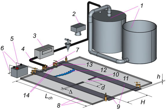
Figure 1.
Schematic diagram of the experimental facility: displacement gas meter (1), high-speed video camera (2), gas flow meter (3), gas mixture supply hose (4), spark discharger (5), electric wires (6), tube with flame arrester (7), flat channel (8), side walls of the channel (9), barrier (10), hole in the barrier (11), flame front (12), end plate of the channel (13), electrodes (14).
Inside the channel, a 3D-printed thermoplastic polyurethane (TPU) barrier of height
, length
, and width ∆ was installed, separating the closed and open chambers of the channel. The barrier had a gap (hole) of width
in its central portion, located symmetrically about the channel width.
The combustible mixture was ignited by a spark generated by two electrodes located in the central part of the closed end of the channel. The voltage applied from the ignition coil to the electrodes was 35 kV, the spark discharge duration was 2.2 ms, and the discharge energy was 50 mJ.
After ignition, a flame propagated from the closed end to the open end of the channel, passing through the hole in the barrier. The flame propagation was recorded by a high-speed video camera GoPro HERO12 camera (manufactured by GoPro company, San Mateo, CA, USA) mounted above the Hele-Shaw flat channel on a stationary tripod. The camera was positioned right above the center of the hole in the barrier at a height of 0.7 m that allowed both ends of the flat channel to be covered by the field of view. The video recording rate was 240 frames per second.
2.2. Parameters and Experimental Procedure
Experiments were performed for the following geometrical parameters of the channel: length
mm and width
mm. The distance between the parallel plates (gap width) was fixed in all the experiments at
mm. The barrier of width
mm was located at half the channel length, so that the closed and open chambers of the channel were of the same length,
mm. The width of the hole in the barrier was varied in the range
mm, providing the blockage ratio
between
and
, respectively.
Before each experiment, the whole channel, having the internal volume of 1.2 L, was filled with a combustible gas mixture prepared in the two-volume displacement gas meter of 15 L capacity. The mixture was prepared at the relative accuracy of concentration within 0.4%. The mixture was fed into the Hele-Shaw channel through a valve available in its closed-end plug. To ensure that air or combustion products from the previous test were displaced completely out of the channel, 6.5 to 7 L of combustible mixture (5.4–5.8 times the channel volume) were fed at an average rate of 2.5–3.5 L/min (the filling time was about 2 min). This amount of gas was shown to be sufficient for filling the whole channel with fresh mixture by numerical simulations performed by OpenFOAM v1906 software. It was found that no air was left in the channel (including the corners formed by the barrier or side walls) after purging it with 5–6 channel volumes of combustible mixture.
In the process of channel filling, measures were taken to prevent mixture dilution by the ambient air: during the whole filling process, a porous plug made from dense tissue was fitted to the far end of the channel. With this plug, the gas could be filtered out of the channel due to the developing pressure difference, while any possible backflows or diffusion air fluxes were effectively suppressed. After the prescribed volume of combustible mixture was fed into the channel, the valve in the gas supply hose was closed, and the system stayed with the porous plug intact for 30 s to damp the gas mixture flows in the channel. Following this delay time, the plug was removed, and ignition occurred.
In each experiment, video recording of flame propagation was taken and post-processed to obtain the instantaneous flame shape and coordinate, as well as the global flame evolution features. Processing of each video frame was automated and implemented in Python 3.14.2 using the OpenCV library [40]. The region containing the channel was extracted from the frames, and all subsequent processing was performed on this specific region. The area where the barrier is located was cropped from the channel images by applying a color-based mask. The OpenCV medianBlur filter was applied to the frames to remove possible noise arising from recording under low-light conditions. Pixels with brightness below a threshold value were removed from the frames. The parameters for medianBlur and the threshold value were selected manually. After this processing, no objects other than the flame front remained in the frames. Then, contours were detected in the frames by findContours procedure from OpenCV. Among all contour points, the point that had advanced the farthest along the channel was selected and taken as the leading point of the flame front.
In order to visualize the global flame propagation history, large number of frames were overlain to produce a single image. The frames were selected at a fixed time step, so that the distances between the consecutive fronts indicated the local visible flame propagation speed. The time step was chosen such that individual flame front shapes and positions were distinguishable. Generally, the post-processing procedure was the same as in the earlier works [35,36]; the algorithm was enhanced to embrace the cases where a single flame front was split into several parts due to local flame extinguishment.
It was found in the preliminary experiments that, with the same initial conditions and channel geometry, including the hole width
, different outcomes were possible concerning the flame interaction with the obstacle: in some cases, combustion wave passed through the hole and proceeded into the semi-open channel section, while, in other cases, flame was extinguished before reaching the hole, or shortly after it. This rather unexpected result, where probabilistic behavior is found for a seemingly deterministic (laminar flame) system, deserved special attention. In order to evaluate the probability of flame passage through the hole, each experiment was repeated 10 to 30 times.
3. Results
3.1. Summary of Experiments on Flame Passage Through the Hole
Once a barrier with a hole is installed, the flame propagating from the ignition point can either pass through the hole, igniting the mixture in the semi-open channel barrier, or be extinguished, leaving (all or some) mixture in the semi-open channel part unburnt.
In order to obtain the probability of flame passage through the hole, a large set of experiments on the burning of the stoichiometric methane-air mixture was carried out, with different sizes of the hole
. Parameters of all experiments, as well as the results obtained are summarized in Table 1 where the number of experiments performed is given together with the number of tests where flame passage was obtained; the ratio of these numbers gives an estimate of the passage probability
given in the rightmost column. The flame passage probabilities
are also plotted in Figure 2 as a function of the hole width
.

Table 1.
Summary of experiments on CH4-air flame passage through hole in the internal barrier.
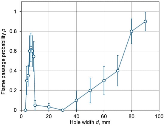
Figure 2.
Probability of the stoichiometric methane-air flame passage through a hole in the barrier vs. hole width
; standard deviations of the sampling uncertainty are shown by vertical error bars.
The flame passage probabilities presented in Table 1 and Figure 2 were obtained from a finite (10 to 30) number of tests and, as such, they bear a statistical uncertainty known as the sampling error. The difference between the observed (empirical) probability
and the theoretical (exact) probability
occurring due to finite sample length
(so-called sampling variability) is characterized by the standard deviation (the Law of Large Numbers) [41]:
The values of flame passage probabilities given in Table 1 are supplemented by the uncertainty intervals, given as
. In Figure 2, the error bars representing the standard deviations evaluated according to the above formula are also added.
The data presented in Figure 2 may seem counter-intuitive: indeed, it is well-known that flames cannot pass through small openings because their propagation is suppressed by the heat losses and excessive flame front curvature arising in small holes and leading to flame extinguishment [23]. Our experiments have also shown that flames were unable to pass through holes in the barrier whenever the hole width
was equal or less than 3 mm. It could be expected that the flame passing probability
would increase monotonically with the hole width
(equivalent to diminution of the blockage ratio
), reaching unity for large enough holes (
).
However, the experimental results presented in Figure 2 clearly indicate that the dependence
is non-monotonic; rather, it is bimodal. For large openings (
mm) the function
indeed increases monotonically from zero to one, but for small holes (
mm), it peaks with a maximum of
at
mm.
This result was unexpected and had never been previously described in the literature. In particular, the presence of a minimum in the
function in the range
mm was not expected.
The fact that the probability of flame passage through the perforated barrier has a pronounced minimum at intermediate hole sizes (about
mm) cannot be explained by the influence of additional heat losses to the side walls of the perforation in the barrier. These heat losses are negligible in comparison to the heat losses to upper and lower glass walls of the Hele-Shaw channel (the distance between these walls in all experiments was as small as
mm, which is an order of magnitude smaller than the hole sizes in question). Therefore, the non-monotonic behavior of flame passage probability must be related to other phenomena, including the gas flows developing near the orifice.
In order to clarify the scenarios leading to flame passage or extinguishment, we analyze below the sequence of events accompanying success or failure of flame passage, starting with large hole size (
mm,
%), then diminishing it to
mm (
and finally
mm (
%).
3.2. Flame Passage Through Large Holes
As an example of a large hole for which the flame passage probability is high (90%) and extinctions are just occasional, consider first the results obtained for the hole size
mm. In Figure 3a,b, the combined photographs of flame fronts are shown for this case; successful flame passage occurred in the first experiment, (a), while it failed in the second one (b). Spark ignition was near the left (closed) end of the channel. Note that, in all the photos, the last (rightmost) visible flame front is the final one before extinction.
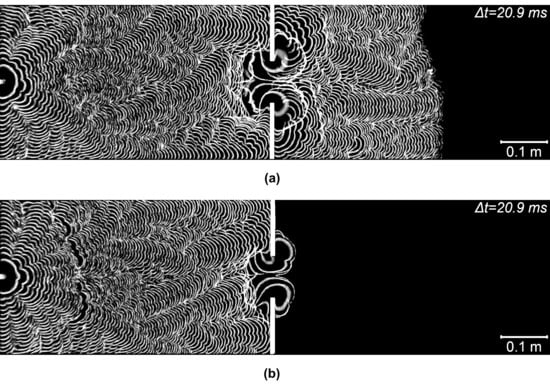
Figure 3.
Typical scenarios of flame passage through a barrier with a hole of
mm: (a) flame passage; (b) flame extinguishment.
Figure 3a shows the flame that passed successfully through the barrier and was extinguished much later when it reached the gas near the right (outlet) channel boundary diluted by air. The case shown in Figure 3b presents the true flame extinguishment near the hole. To elucidate the flame histories resulting in different outcomes, the instantaneous flame fronts corresponding to Figure 3a are shown in Figure 4.
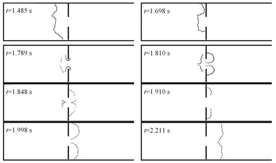
Figure 4.
Flame passage through hole
mm, see Figure 3a.
The flame fronts presented in Figure 4 demonstrate an interesting feature of the process: as the flame approaches the hole in the barrier, the flame portion just opposite the orifice is decelerated (see Figure 4,
s) and then breaks up into two unconnected segments (
s). This indicates that a reverse (i.e., directed right-to-left) gas flow develops through the orifice, causing local extinguishment. Burning of this fresh mixture leads to the appearance of a new flame front segment (see Figure 4,
s) and flame passage through the hole (
s). Notably, at
s the flame is again broken into two segments, which may indicate that the burnt gas is expelled from the hole, trailing the flame. The flame front then regains its integrity and propagates further into the right channel section. Alternatively, in few cases the flame was extinguished by this flow of burnt gas. Thus, the evolution of flame fronts suggests that the hole in the barrier is “breathing” in alternating directions, rather than just blowing gas from the left channel section to the right one. Reasons for such behavior will be discussed below, after considering results obtained for other hole sizes.
In Figure 5a,b, the time histories of the flame leading point coordinate are plotted for all experiments performed for the same geometry and experimental conditions; different colors denote individual tests within the total of 10 runs (see the bottom line in Table 1). For clarity, the curves corresponding to the cases of flame passage and extinguishment are plotted separately; the barrier position is denoted by the horizontal bar. It can be seen that flame propagation is quite repeatable as long as the flame is located far from the barrier. On the contrary, flame disturbances near the hole occur rather sporadically, indicating a degree of stochasticity present in the flame interaction with the flows issuing from the hole.
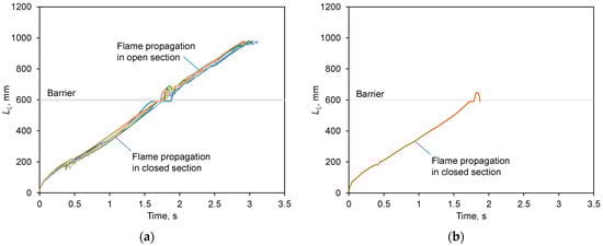
Figure 5.
Leading flame point coordinates in the experiments for
mm: (a) flame passage; (b) flame extinguishment. Barrier position at 600 mm is shown by horizontal bar.
3.3. Flame Passage Through Medium-Size Holes
As a representative example of intermediate-sized hole, consider the case of
mm where the flame passage probability was just 20% (see Table 1 and Figure 2). In Figure 6a,b, the overlaid flame fronts are shown for the experiments where the was extinguished after the barrier (a) and before it (b). In Figure 7, the flame front shapes at different instants are shown for the case of flame extinguishment before the barrier. The time histories of the flame leading point coordinate for all repeatability tests performed for the same geometry and experimental conditions are shown by different colors in Figure 8.
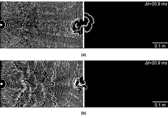
Figure 6.
Flame extinguishment before (a) and after (b) the barrier with a hole of d = 50 mm.
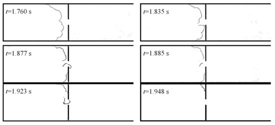
Figure 7.
Flame extinguishment before the barrier,
mm, see Figure 6b.
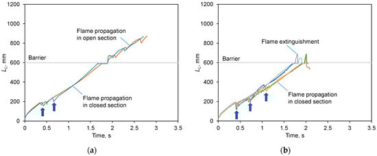
Figure 8.
Leading flame point coordinates in all experiments for
mm: (a) flame passage; (b) flame extinguishment. Arrows show the instants of flame front rupture.
3.4. Flame Passage Through Small Holes
For a hole where
mm, the passage probability increased to 62% (see Table 1 and Figure 2), which is much higher than what was observed for larger (intermediate) holes. Figure 9, Figure 10 and Figure 11 show the flame fronts and their leading coordinates. Flame extinguished also occurred in two modes, either after the barrier, when a “bubble” was formed (see Figure 9b), or before the barrier (similar to Figure 6b in the case discussed in the previous section).
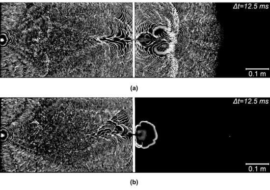
Figure 9.
Flame passage through a barrier with a hole of
mm: (a) flame passage; (b) extinguishment after barrier with “bubble” formation.
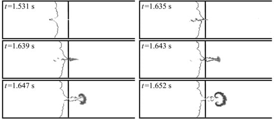
Figure 10.
Flame passage through hole
mm, see Figure 9a.
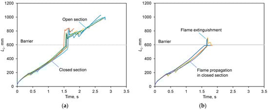
Figure 11.
Leading flame point coordinates in all experiments for
mm: (a) flame passage; (b) flame extinguishment.
4. Discussion
Analysis of the video recordings obtained in the experiments on flame propagation in a Hele-Shaw channel with a single-hole internal barrier revealed some common features of the flame behavior in the closed channel section, as well as near the hole.
For proper interpretation of the results obtained, it is necessary to consider the specific features of the Hele-Shaw channel used in the experiments. As can be seen in Figure 1, the combustion chamber consists of two sections, the closed one (where ignition takes place) and the open one; these two sections are connected by a rather small hole in the dividing barrier. For the particular geometry of the channel, the cross section area of the largest hole (
mm) through which the gas flow between the sections occurs is 2.7 cm2, while the total area of two channel walls in the closed section (determining the heat losses) is
cm2, making the gas cooling by the closely spaced channel walls very efficient.
Due to the high blockage ratio limiting the gas flow rate through the hole, pressure drop can develop across the barrier. After ignition of combustible mixture, rapid expansion of combustion products occurs; the pressure in the channel section before the barrier increases monotonically, exceeding the pressure behind the barrier (approximately equal to the ambient pressure). However, intensive heat losses from the hot combustion products to cold channel walls result in gas shrinking (due to the temperature decrease). The high drag in the narrow channel results in much slower pressure equalization over the Hele-Shaw channel in comparison with large channels or unconfined systems where pressure equalization occurs at a sonic speed (isobaric combustion). Therefore, the flow in the channel possesses “inertia” (of dissipative nature), making it somewhat similar to the Helmholtz resonator.
With the two processes running concurrently (gas expansion due to combustion heat release and gas shrinking due to cooling by channel walls), the pressure drop across the perforation can change its sign with time, resulting in the alternating flow direction through the hole. Driven by this flow, a gas jet emerges on the downwind side of the orifice, blowing into the open or closed channel sections in accordance with the pressure drop sign.
Occurrence of the gas jet directed towards the approaching flame is proven by the periodic rupture of the flame front at its central point, breaking the flame into two symmetric fragments that propagate further and then merge back into a continuous flame front. Such events occur quite far from the barrier, they are clearly visible on the time histories of the flame leading point, as sudden discontinuities (indicated by arrows in Figure 8, also identifiable in Figure 5 and Figure 11).
It is necessary to note that by “local extinguishment” leading to flame front breaking, we mean the disappearance of some fragments of the visible flame or thin glowing zone. For example, Figure 4, Figure 7 and Figure 10 show that the continuous flame breaks, forming continuous front pieces separated by “holes” between them. Of course, chemical reactions may (and most likely do) still run in these latter areas (if there is a combustible mixture, then, according to Arrhenius’s law, the reaction rate is nonzero even at low temperatures), but these reactions do not form a visible flame front. Our camera sensitivity was sufficient to record the flame front at all times, and disappearance of flame front fragments indicates a sharp decrease in the rate of chemical reactions and the associated thermal radiation and chemiluminescence, which is referred to as “local extinguishment”. Actually, we never observed flames reappearing from the areas where they had been extinguished (i.e., where the flame front had broken). Flames never reappeared from the “empty space;” on the contrary, the dark areas were only reignited when existing (visible) pieces of flame front propagated into them.
As the flame approaches the orifice, almost in all experiments it is broken into two segments by the impingement of a cold gas jet from the orifice (see Figure 4 at
s, Figure 7 at
s, Figure 10 at
s). This gas, flowing from the right channel section, is combustible; the reverse flow brings a portion of fresh mixture into the zone with high-temperature combustion products. Ignition and rapid combustion of the fresh portion of combustible mixture leads to local pressure rise ahead of the barrier. As a result, a positive pressure drop arises across the barrier, which leads to the ejection of a hot gas jet through the hole into the open channel part.
If at this moment the flame front approaches the orifice, a burning jet (flame) is ejected into the region behind the barrier. This is clearly visible in Figure 10 at times
s. The ejection of burning jet leads to the ignition of the initial combustible mixture behind the barrier, which ensures further flame propagation beyond the barrier.
However, the impact of the reverse jet may not only break the flame front, but can also lead to flame extinguishment, with the newly introduced mixture reacting gradually. Alternatively, the combustion products injected into the open channel part can blow off the flame or dilute the mixture, also causing the flame extinguishment, visible as a bursting “bubble”.
It must be emphasized that the processes of gas heating and cooling are nonlinear and proceed unevenly over the channel volume. The total heat release rate depends not only on the local burning rate in the flame, but also on the flame curvature and surface area; the heat losses include both the conductive and convective components. Even more complex are the processes of flame interaction with gas jets originating from the hole in the perforated barrier. Taken together, these coupled processes with multiple feedbacks between flow and chemistry, result in the probabilistic behavior of flame penetration through a single-hole perforated barrier.
The results presented in Figure 2 show that, with the channel geometry fixed, the probability of flame passage depends on the hole size non-monotonically. In our particular case, the hole size of
mm provides the strongest flame-flow interaction and the least favorable conditions for the methane-air flame passage.
In future studies, we plan to conduct a detailed numerical study of the process that will allow us to reproduce the alternate blowing jet and estimate its velocity.
5. Conclusions
In the current studies conducted in semi-open Hele-Shaw channels with an internal perforated barrier, the features of flame propagation and passage through the opening from the closed to open part of the channel were identified.
The principal novel result obtained in this work was the demonstration of probabilistic behavior of flame passage through a hole in the barrier: for the same experimental conditions, in some experiments the flame passed through the hole, while in others the flame was extinguished near the orifice. This behavior is quite unusual for laminar flames that are considered to be deterministic in their nature.
By performing multiple runs at fixed conditions, we evaluated the flame passage probability (
) and found its dependence on the hole size,
. No similar result is known to us in the literature on flame/barrier interactions. Usually, the critical conditions are typically determined in a “yes/no” manner, i.e.,
or
.
The main conclusions drawn from the results obtained are the following:
- The primary driver of gas flow is the pressure generated by the thermal expansion of hot combustion products. An opposite effect is attributed to the cooling of hot combustion products by the channel walls; it leads to gas shrinking and pressure decrease in the closed channel section.
- The small size of the hole in the barrier slows down the pressure equalization between the channel sections, significantly affecting the flow characteristics and flame propagation dynamics. Gas mixture ignition in the closed section of the channel leads to pressure rise, causing accelerating gas flow through the opening into the open section of the channel. This outflow promotes gas turbulization in the open section, so that the passage of flame through the hole in the barrier causes rapid ignition and burning of the remaining fresh mixture.
- For larger hole sizes, the processes of pressure equalization between the closed and open channel sections run faster, and the effects of mixture turbulization become less pronounced. Nevertheless, the arising gas flows play an important role in flame propagation near the orifice, causing local flame extinctions and, in some conditions, global flame extinguishment.
- The number of repetitions performed for each hole size in this scoping study (mostly 10; up to 30 in some cases) allows the flame passage probability to be determined only approximately (in the statistical sense). However, the standard deviations of the probabilities evaluated from the Law of Large Numbers and shown in Table 1 and Figure 2 show that this number of repetitions is sufficient to establish the trend. Of particular interest and novelty is the bimodal distribution found, with the local maximum at d = 7 mm and local minimum at d = 30 mm (in the latter case, none of the 10 tests resulted in flame passage).
- When planning the experimental series (total of 212 experiments are listed in Table 1, each requiring meticulous preparation and conduction), it was decided to focus on the establishment of the general trend and boundaries of the probability peak observed at smaller gaps, rather than on obtaining higher accuracy at some particular point. In the future, we plan to repeat the experiments for several values of aperture width d to refine the probabilities, but we are confident that the qualitative picture obtained in this study will remain unchanged.
- The problem of flame passage through a perforated barrier reveals complex flame-flow interactions that depend not only on the combustion characteristics of the mixture, but also on the channel geometry. Therefore, more extensive experimental studies and numerical simulations are necessary in order to generalize the results obtained in the current work.
The findings of this work have significant practical implications for fire safety and fire prevention in built environment and industrial sites. Flame penetration through very small openings, cracks, and leaks in enclosing structures can be an effective mechanism for the rapid spread of fire between different rooms. The penetration of flame and hot combustion products through microscopic openings typically goes unnoticed during visual inspection, as it is not accompanied by obvious signs of damage or deformation of the enclosure. Consequently, the risk of fire spread due to small defects is significantly higher than what is predicted by standard calculation models. It is important to keep in mind that the speed and efficiency of flame transmission through openings can vary significantly depending on the size, shape, and location of the defects, as well as the humidity, temperature, and gas composition within the building. Therefore, when designing fire protection systems, it is necessary to consider not only potential major damage but also microscopic defects, which can play a critical role in the spread of fire.
Author Contributions
Conceptualization and methodology, S.Y., S.R., O.S. and M.A.; experiments, O.S. and M.A.; visualization, O.S. and M.A.; data analysis, S.R., O.S. and M.A.; writing—original draft preparation, S.R., O.S. and M.A.; writing—review and editing, S.Y. and S.R. All authors have read and agreed to the published version of the manuscript.
Funding
This research was funded by the Ministry of Science and Higher Education of Russia, agreement No. 075-15-2024-543 of 24 April 2024.
Institutional Review Board Statement
Not applicable.
Informed Consent Statement
Not applicable.
Data Availability Statement
The original contributions presented in this study are included in the article. Further inquiries can be directed to the corresponding author.
Conflicts of Interest
The authors declare no conflicts of interest. The funders had no role in the design of this study; in the collection, analyses, or interpretation of the data; in the writing of the manuscript; or in the decision to publish the results.
Abbreviations
The following abbreviations are used in this manuscript:
| BR | Blocking ratio |
| DDT | Deflagration to Detonation Transition |
| MEMS | Micro electro-mechanical systems |
| PETG | Polyethylene terephthalate glycol |
| TPU | Thermoplastic polyurethane |
References
- Makhviladze, G.M.; Yakush, S.E. Large-scale unconfined fires and explosions. Proc. Combust. Inst. 2002, 29, 195–210. [Google Scholar] [CrossRef]
- Bradley, D.; Chamberlain, G.A.; Drysdale, D.D. Large vapour cloud explosions, with particular reference to that at Buncefield. Philos. Trans. R. Soc. A Math. Phys. Eng. Sci. 2012, 370, 544–566. [Google Scholar] [CrossRef]
- Shchelkin, K.I.; Troshin, Y.K. Non-stationary phenomena in the gaseous detonation front. Combust. Flame 1963, 7, 143–151. [Google Scholar] [CrossRef]
- Lee, J.H.S.; Moen, I.O. The mechanism of transition from deflagration to detonation in vapor cloud explosions. Prog. Energy Combust. Sci. 1980, 6, 359–389. [Google Scholar] [CrossRef]
- Escofet-Martin, D.; Chien, Y.-C.; Dunn-Rankin, D.; Dzieminska, E.; Hayashi, A.K.; Hanada, S. Flame propagation in a narrow closed channel: Effects of aspect ratios, blockage ratio, and mixture reactivity on flame speed and pressure dynamics. Combust. Sci. Technol. 2020, 192, 986–996. [Google Scholar] [CrossRef]
- Luo, G.; Tu, J.-Q.; Qian, Y.-L.; Jin, K.-K.; Ye, T.-J.; Bai, Y.; Gao, S. Impacts of rectangular obstacle lengths on premixed methane–air flame propagation in a closed tube. Combust. Explos. Shock Waves 2022, 58, 10–21. [Google Scholar] [CrossRef]
- Guo, B.; Gao, J.; Hao, B.; Ai, B.; Hong, B.; Jiang, X. Experimental and numerical study on the explosion dynamics of the non-uniform liquefied petroleum gas and air mixture in a channel with mixed obstacles. Energies 2022, 15, 7999. [Google Scholar] [CrossRef]
- Gao, J.; Ai, B.; Hao, B.; Guo, B.; Hong, B.; Jiang, X. Effect of obstacles gradient arrangement on non-uniformly distributed LPG–Air premixed gas deflagration. Energies 2022, 15, 6872. [Google Scholar] [CrossRef]
- Ugarte, O.J.; Bychkov, V.; Sadek, J.; Valiev, D.; Akkerman, V. Critical role of blockage ratio for flame acceleration in channels with tightly spaced obstacles. Phys. Fluids 2016, 28, 093602. [Google Scholar] [CrossRef]
- Feng, X.; Huang, X. Influence of variable blocking ratio on DDT process. Energies 2022, 15, 7706. [Google Scholar] [CrossRef]
- Shimo, M.; Heister, S.D. Schlieren visualization of multicyclic flame acceleration process in valveless pulsed detonation combustors. Combust. Sci. Technol. 2008, 180, 1613–1636. [Google Scholar] [CrossRef]
- Johansen, C.; Ciccarelli, G. Visualization of the unburned gas flow field ahead of an accelerating flame in an obstructed square channel. Combust. Flame 2009, 156, 405–416. [Google Scholar] [CrossRef]
- Boeck, L.R.; Lapointe, S.; Melguizo-Gavilanes, J.; Ciccarelli, G. Flame propagation across an obstacle: OH-PLIF and 2-D simulations with detailed chemistry. Proc. Combust. Inst. 2017, 36, 2799–2806. [Google Scholar] [CrossRef]
- Dai, Q.; Zhang, S.; Zhang, S.; Sun, H.; Huang, M. Large Eddy Simulation of premixed CH 4 /Air deflagration in a duct with obstacles at different heights. ACS Omega 2021, 6, 27140–27149. [Google Scholar] [CrossRef]
- Mishra, A.; Agarwal, K.; Kumar, M. Sensitivity of key simulation parameters on flame propagation in obstructed chamber: Effect of XiFOAM discretization schemes. J. Fluid Flow Heat Mass Transf. 2024, 11, 177–186. [Google Scholar] [CrossRef]
- Gussak, L.A.; Karpov, V.P.; Tikhonov, Y.V. The Application of LAG-Process in Pre-Chamber Engines; SAE Technical Paper; SAE: Warrendale, PA, USA, 1979; p. 790692. [Google Scholar]
- Oppenheim, A.K. Dynamics of Combustion Systems, 2nd ed.; Springer: Berlin/Heidelberg, Germany; New York, NY, USA, 2008; ISBN 9783540773634. [Google Scholar]
- Tian, J.; Cui, Z.; Ren, Z.; Tian, H.; Long, W. Experimental study on jet ignition and combustion processes of natural gas. Fuel 2020, 262, 116467. [Google Scholar] [CrossRef]
- Liu, P.; Zhong, L.; Zhou, L.; Wei, H. The ignition characteristics of the pre-chamber turbulent jet ignition of the hydrogen and methane based on different orifices. Int. J. Hydrogen Energy 2021, 46, 37083–37097. [Google Scholar] [CrossRef]
- Rubtsov, N.M.; Alymov, M.I.; Kalinin, A.P.; Vinogradov, A.N.; Rodionov, A.I. Remote Studies of Combustion and Explosion Processes Based on Optoelectronic Methods; AUS Publishers: Melbourne, Australia, 2022; ISBN 9781922756077. [Google Scholar]
- Carnasciali, F.; Lee, J.H.S.; Knystautas, R. Turbulent Jet Initiation of Detonation. Combust. Flame 1991, 84, 170–180. [Google Scholar] [CrossRef]
- Ju, Y.; Maruta, K. Microscale combustion: Technology development and fundamental research. Prog. Energy Combust. Sci. 2011, 37, 669–715. [Google Scholar] [CrossRef]
- Zeldovich, Y.B.; Barenblatt, G.I.; Librovich, V.B.; Makhviladze, G.M. The Mathematical Theory of Combustion and Explosions; Consultants Bureau: New York, NY, USA, 1985. [Google Scholar]
- Hele-Shaw, H.S. The flow of water. Nature 1898, 58, 34–36. [Google Scholar] [CrossRef]
- Joulin, G.; Sivashinsky, G.I. Influence of momentum and heat losses on the large-scale stability of quasi-2D premixed flames. Combust. Sci. Technol. 1994, 98, 11–23. [Google Scholar] [CrossRef]
- Almarcha, C.; Radisson, B.; Al Sarraf, E.; Villermaux, E.; Denet, B.; Quinard, J. Interface dynamics, pole trajectories, and cell size statistics. Phys. Rev. E 2018, 98, 030202. [Google Scholar] [CrossRef]
- Alexeev, M.M.; Semenov, O.Y.; Yakush, S.E. Experimental study on cellular premixed propane flames in a narrow gap between parallel plates. Combust. Sci. Technol. 2018, 191, 1256–1275. [Google Scholar] [CrossRef]
- Elyanov, A.; Golub, V.; Volodin, V. Premixed hydrogen–air flame front dynamics in channels with central and peripheral ignition. Int. J. Hydrogen Energy 2022, 47, 22602–22615. [Google Scholar] [CrossRef]
- Veiga-López, F.; Kuznetsov, M.; Martínez-Ruiz, D.; Fernández-Tarrazo, E.; Grune, J.; Sánchez-Sanz, M. Unexpected propagation of ultra-lean hydrogen flames in narrow gaps. Phys. Rev. Lett. 2020, 124, 174501. [Google Scholar] [CrossRef]
- Chang, J.; Zhu, W.; Kang, X. An experimental study on premixed methane–air flame propagation with intrinsic instabilities in a Hele-Shaw chamber at various inclined angles. Combust. Sci. Technol. 2024, 197, 3907–3929. [Google Scholar] [CrossRef]
- Chen, D.; Ma, H.; Shen, Z.; Yao, Y. Investigation of the quenching of methane-air deflagration in narrow parallel channels. Process Saf. Prog. 2020, 39, e12126. [Google Scholar] [CrossRef]
- Lu, Y.; Guo, P.; Wang, Z.; Wang, X.; Chen, Y. Investigation on quenching characteristics of parallel narrow channels for deflagration flames. Fire Mater. 2023, 47, 853–862. [Google Scholar] [CrossRef]
- Fernández-Galisteo, D.; Kurdyumov, V.N.; Ronney, P.D. Analysis of premixed flame propagation between two closely-spaced parallel plates. Combust. Flame 2018, 190, 133–145. [Google Scholar] [CrossRef]
- Borisov, V.E.; Yakush, S.E.; Sysoeva, E.Y. Numerical simulation of cellular flame propagation in narrow gaps. Math. Model. Comput. Simul. 2022, 14, 755–770. [Google Scholar] [CrossRef]
- Alexeev, M.M.; Semenov, O.Y.; Rashkovskiy, S.A.; Yakush, S.E. Stoichiometric methane–air flame propagation in a diverging Hele-Shaw channel. Combust. Sci. Technol. 2024, 197, 6803–6830. [Google Scholar] [CrossRef]
- Yakush, S.; Rashkovskiy, S.; Alexeev, M.; Semenov, O. Features of hydrogen-enriched methane–air flames propagating in Hele-Shaw channels. Energies 2025, 18, 335. [Google Scholar] [CrossRef]
- Zhou, L.; Zhong, L.; Zhao, J.; Pan, J.; Xu, Z.; Wei, H. Flame propagation and combustion phenomena in a confined space with the perforated plate at different positions. Combust. Sci. Technol. 2020, 192, 493–512. [Google Scholar] [CrossRef]
- Wei, H.; Li, K.; Zhao, J.; Zhou, L. Experimental investigation on the propagation of flow and flame in a confined combustion chamber equipped with a single-hole perforated plate. Int. J. Hydrogen Energy 2020, 45, 32589–32597. [Google Scholar] [CrossRef]
- Yakush, S.; Semenov, O.; Alexeev, M. Premixed propane–air flame propagation in a narrow channel with obstacles. Energies 2023, 16, 1516. [Google Scholar] [CrossRef]
- OpenCV: Open Source Computer Vision Library. Available online: https://opencv.org (accessed on 10 January 2026).
- Devore, J.L.; Berk, K.N. Modern Mathematical Statistics with Applications; Springer: New York, NY, USA; Dordrecht, The Netherlands; Berlin/Heidelberg, Germany; London, UK, 2012. [Google Scholar] [CrossRef]


Disclaimer/Publisher’s Note: The statements, opinions and data contained in all publications are solely those of the individual author(s) and contributor(s) and not of MDPI and/or the editor(s). MDPI and/or the editor(s) disclaim responsibility for any injury to people or property resulting from any ideas, methods, instructions or products referred to in the content. |
© 2026 by the authors. Licensee MDPI, Basel, Switzerland. This article is an open access article distributed under the terms and conditions of the Creative Commons Attribution (CC BY) license.