Abstract
Complex fluid interfaces are commonplace in natural and engineered systems and a major topic in the fields of rheology and soft matter physics, providing boundary conditions for a system’s hydrodynamics. The relationship between structure and function dictates how constituents within complex fluids govern flow behavior via constituents changing conformation in response to the local microenvironment to minimize free energy. Both hydrodynamics, such as shear flow, and the presence of air–liquid interfaces are principal aspects of a complex fluid’s environment. The study of fluid interfaces coupled to bulk flows can be uniquely advanced through experimentation in microgravity, where surface tension containment can be achieved at relatively large length scales. This computational investigation assesses flow in the ring-sheared drop (RSD), a containerless biochemical reactor operating aboard the International Space Station for the study of complex fluids and soft matter physics. Specifically, the hydrodynamic effects of a generalized Boussinesq–Scriven interface with a shear-thinning surface shear viscosity are examined in flow regimes where the air–liquid interface remains coupled to the Newtonian bulk fluid. The results verify this interfacial model’s ability to affect system-wide hydrodynamics under specific parameter regimes, enabling future model validation with high-precision rheological measurements.
1. Introduction
Understanding the flow of complex fluid interfaces is central to deciphering the behavior of both natural systems (e.g., physiology [1] and the environment [2]) and engineered systems (e.g., manufacturing [3,4] and medicine [5]). Complex fluids contain distinct constituents such as colloids, foams, emulsions, polymers, proteins, or gels [6]. Soft matter physics and rheology provide constitutive relations to describe flow processes including shear rate dependence, polymerization and fibrillization, viscoelasticity, and material phase transitions. The adage “structure determines function” highlights the key concept of these systems: that the constituents within a fluid define flow response. The structure and state of such constituents is controlled by the local microenvironment, the micro-scale surroundings encompassing forces produced by solvent composition (e.g., pH, chemical composition), fluid motion (e.g., shearing, extensional flow), body forces (e.g., gravity, field interactions), electromagnetic spectra (e.g., ultraviolet radiation), and thermodynamics (e.g., temperature, pressure, humidity). In response to these local surroundings, molecules progress toward the minimization of free energy, with the aforementioned applied forces governing navigation through a molecule’s energetic landscape [7,8].
Air–liquid interfaces are a principal component of numerous fluid systems, boundary conditions that affect both fluid dynamics and molecular energetics. The air–liquid interface offers conditions energetically favorable to both hydrophilic and hydrophobic chemical structures, resulting in an overabundance of amphiphilic molecules. In this sense, the air–liquid interface acts as a “physical catalyst” that lowers the energetic barrier of an adsorbed molecule to particular low-energy states that are unfavorable within the bulk fluid [8,9]. The unique structure of these low-energy interfacial states results in a corresponding structural uniqueness of the air–liquid interface that manifests as distinct interfacial material properties such as surface excess viscosities. The behavior of such interfaces is often complex, viscosities varying with strain rate, manifesting as a non-Newtonian response [10]. Constitutive viscosity modeling is essential for capturing the behavior of such complex interfaces, requiring comparison to experiments in sufficiently sensitive flow systems.
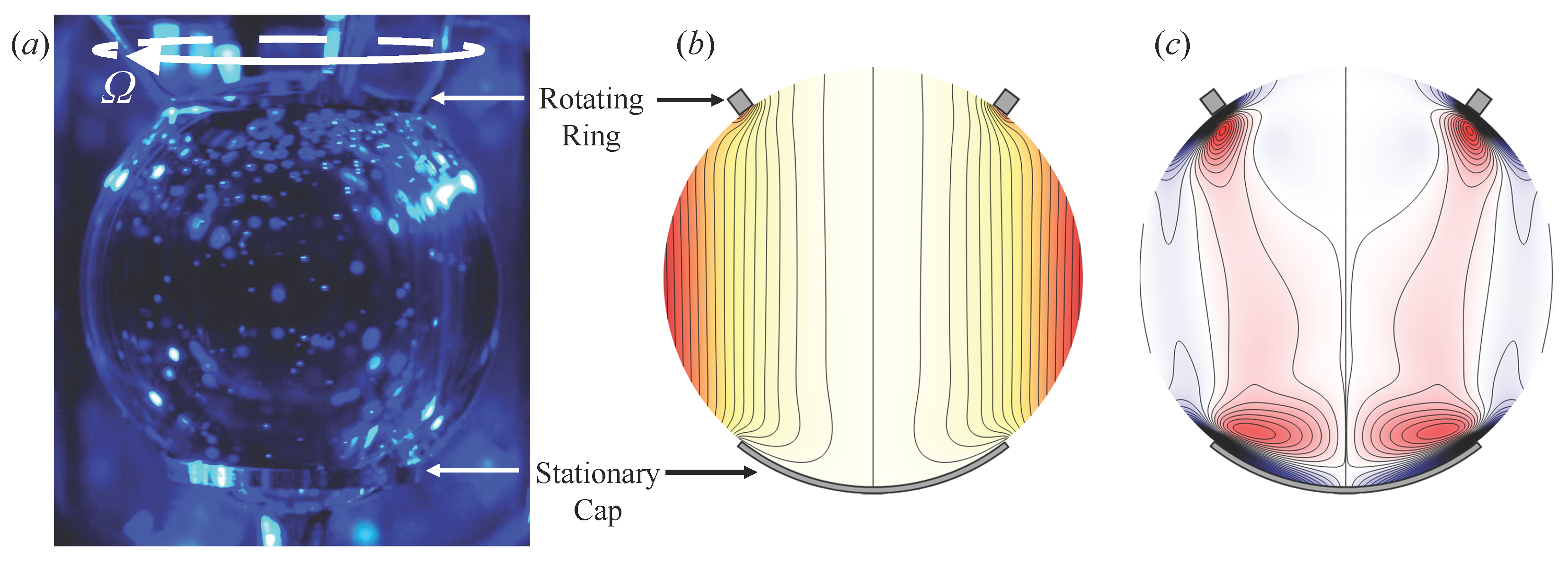
Experimentation in microgravity can facilitate the study of capillary surfaces at large scales, with surface tension containment allowing larger length scales in gravity’s absence [11]. At small length scales, highly viscous interfaces become decoupled from bulk flow, whereas larger scales permit the study interfacial to bulk flow coupling. The ring-sheared drop (RSD) is a microgravity biochemical reactor that leverages surface tension to contain a cm diameter drop of liquid that is pinned between a norther rotating contact ring and southern stationary end-cap [12,13,14,15,16,17]. Figure 1a shows a photograph taken aboard the International Space Station (ISS) of the RSD containing a drop consisting of a solution of 2 mg/mL human insulin. Rotation of the ring produces interfacial shear that is transmitted primarily by surface shear viscosity to produce both primary shearing flow around the drop’s axis as well as secondary flow in the azimuthal plane due to inertia. Experiments on the ISS have used the RSD to study fibrillization kinetics [18] and velocimetry techniques [17] in aqueous solutions of the model protein human insulin. Insulin solutions form complex fluids that have been shown to undergo a kinetic fibrillization process in response to fluid shear [19,20,21,22,23] similar to processes associated with amyloid neurodegenerative diseases [24,25,26,27,28,29]. Studies of insulin fibrillization using a deep-channel viscometer [22] and knife-edge viscometer (the Earth analog of the RSD) [23,30] show rich behavior, transitioning from Newtonian to non-Newtonian to viscoelastic hydrogel, demonstrating the wide range of fluid constitutive behavior attributable to biofluids.

Figure 1.
The ring-sheared drop (RSD) with northern rotating ring and southern stationary end-cap. (a) Photograph of an insulin solution comprising the cm diameter RSD during operation on the International Space Station. Computed flow for a Newtonian viscous interface shows (b) vortex lines and (c) azimuthal vorticity for Reynolds number and Boussinesq number .
The present study applies a generalized Boussinesq–Scriven interface [10,31] formulated with a shear-thinning surface shear viscosity to the spherical geometry of the RSD in regimes that remain coupled to a Newtonian bulk. Extensions of classical theory, such as the generalized Boussinesq–Scriven equations, are well suited to studying non-Newtonian interfacial viscosity in coupled systems, as recently demonstrated by Davoust and collaborators [32]. Rheological [33,34,35] and microgravity [36,37] studies of protein drops have noted the effects of the air–liquid interface, manifesting in altered drop hydrodynamics and changes in protein structure. The present investigation uses models previously developed for a cylindrical flow system with a flat air–liquid interface [38], now applied to the spherical RSD, which had previously been modeled only with Newtonian viscosity [14]. This interest in non-Newtonian viscosity modeling was motivated by experimental measurements of protein solution rheology [22], fibrillization [23], and behavior within the RSD [17,18]. The prior Newtonian foundation of RSD computational modeling entailed a Newtonian interface of finite surface shear viscosity coupled to a Newtonian bulk, demonstrating that coupling is dependent on interfacial viscosity, with interfacial and bulk flows decoupling as surface shear viscosity becomes large [14]. The baseline flow of the RSD is shown in Figure 1b,c, respectively showing isocontours of azimuthal angular momentum (vortex lines) and azimuthal vorticity, for a Newtonian interface coupled to a Newtonian bulk. Non-Newtonian effects have been previously assessed in a computational study within the knife-edge viscometer, coupling a shear-thinning interface to a Newtonian bulk flow, demonstrating limiting behavior of this model’s parameters [38]. In the present investigation, this generalized Newtonian shear-thinning model was chosen once again as the surface shear viscosity constitutive relation due to this models’ sufficiently rich physics and relevance to a range of soft matter, including complex fluids formed by many types of polymer and protein solutions [6,10,39,40]. Even so, the present investigation uses the shear-thinning model demonstratively to assess the hypothesis that if an interface exhibits non-Newtonian surface shear viscosity, then coupled system-wide flow will be a function of interfacial parameters. Such constitutive modeling has the potential to enable the experimental validation of first-principle viscosity models theorized to describe a desired complex fluid.
2. Materials and Methods
The RSD geometry (as flown on the ISS; see Figure 1a) consists of a liquid drop with radius cm pinned between two contact rings of radius cm (aspect ratio ). The stationary contact ring is integrated with the drop deployment tube and essentially forms an end-cap in the south pole, and will henceforth be referred to as the stationary end-cap. The width of the rotating ring in contact with the drop is cm, giving a ring width ratio of . The rotating ring steadily shears the drop at an angular velocity rad/s, while the southern end-cap remains stationary. The flow is modeled as steady and axisymmetric with an incompressible Newtonian bulk. With A as the length scale and as the time scale, the non-dimensional Navier–Stokes equations governing the bulk flow are
where p is the pressure, and is the Reynolds number. Measured properties for a relevant protein solution, 2 mg/mL insulin at 22 °C, were utilized in numerical simulations, with kinematic viscosity cm2/s and dynamic shear viscosity g/(cm s).
The boundary condition at the air–liquid interface is modeled according to the generalized Boussinesq–Scriven interfacial stress balance [10,31]. The effects of dilatational viscosity do not manifest as there is no deformation of the interface and even subtle interfacial elasticity associated with surface tension gradients diminishes the interfacial flow in the polar direction, , to zero. As the velocity at the interface has zero components in the polar and interface–normal directions, only the azimuthal component remains [14]. No-slip boundary conditions apply at the rotating ring and stationary end-cap. At the rotating ring, only the azimuthal velocity component is non-zero, given by for polar angle , whereas at the stationary end-cap, , all velocity components vanish. The azimuthal velocity at the air–liquid interface, , is determined from the interfacial stress balance evaluated at the interface , where is the spherical radial direction [10]:
where subscripts denote partial differentiation with respect to the subscript. The left-hand side of (2) is the contribution from bulk stresses evaluated at the interface and the right-hand side accounts for the stress from the interface. Specifically, (2) balances tangential stress exerted on the interface by bulk motion with interfacial stress in the plane of the interface originating from surface excess viscosity, represented by Boussinesq number (). is generally proportional to the ratio of surface shear viscosity and bulk shear viscosity (), computed here using a shear-thinning model [38]:
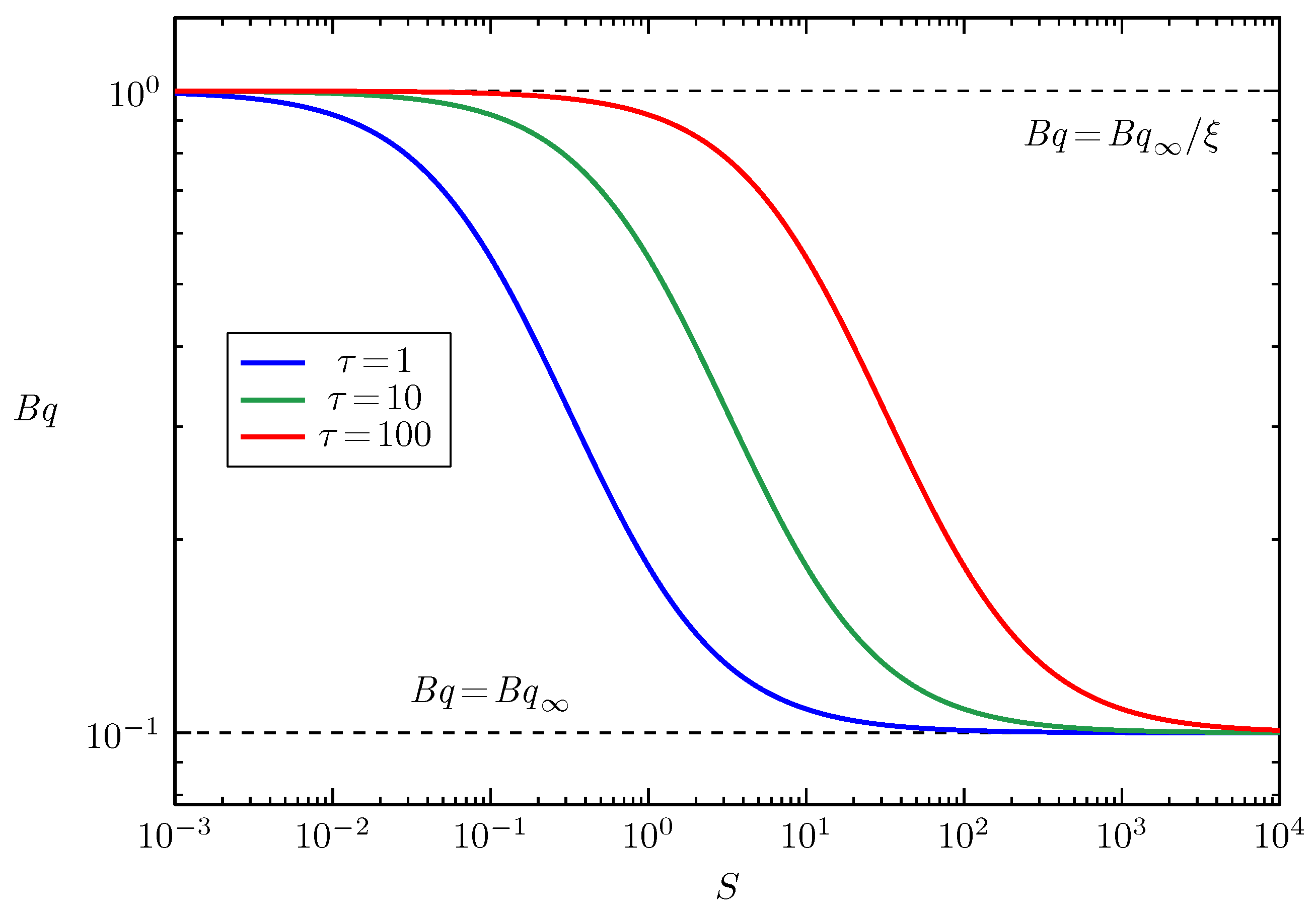
The shear-thinning constitutive model in (3) for surface shear viscosity is defined by a trio of dimensional parameters: the surface shear viscosity at infinite strain rate (units of surface viscosity, g/s), the surface shear viscosity at zero strain rate (units of surface viscosity, g/s), and the characteristic interfacial stress (units of interfacial stress, g/s2) corresponding to the transition between the two viscosities. The non-dimensional forms of these parameters are the infinite-strain-rate Boussinesq number , the viscosity ratio , and the non-dimensional characteristic interfacial stress . The strain rate norm S is the square root of half the Frobenius inner product, represented by ‘:’, of the strain rate tensor evaluated along the interface as a function of polar angle . This model is purely shear-thinning, viscosity monotonically decreasing with increasing strain rate, from a maximum of (representing ) to a minimum of (representing ). The stress at which the fluid transitions from the high viscosity to the low viscosity is controlled by . Figure 2 shows the general shape of the versus S surface shear viscosity constitutive model on a log–log scale. The example curves in Figure 2 represent , , and . Note that specific values of vertical axis intercepts and horizontal axis inflections are case-specific and depend on the combination of , , and .
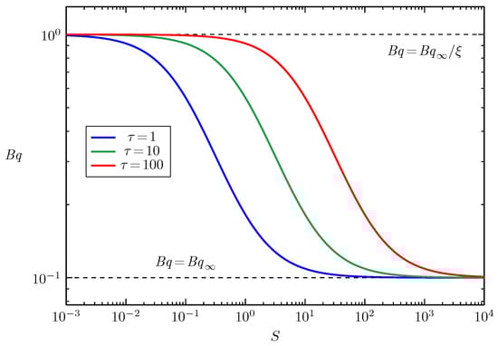
Figure 2.
Boussinesq number versus strain rate norm S for the shear-thinning viscosity model (3); examples are shown for viscosity ratio , infinite strain rate Boussinesq number , and characteristic interfacial stress as indicated.
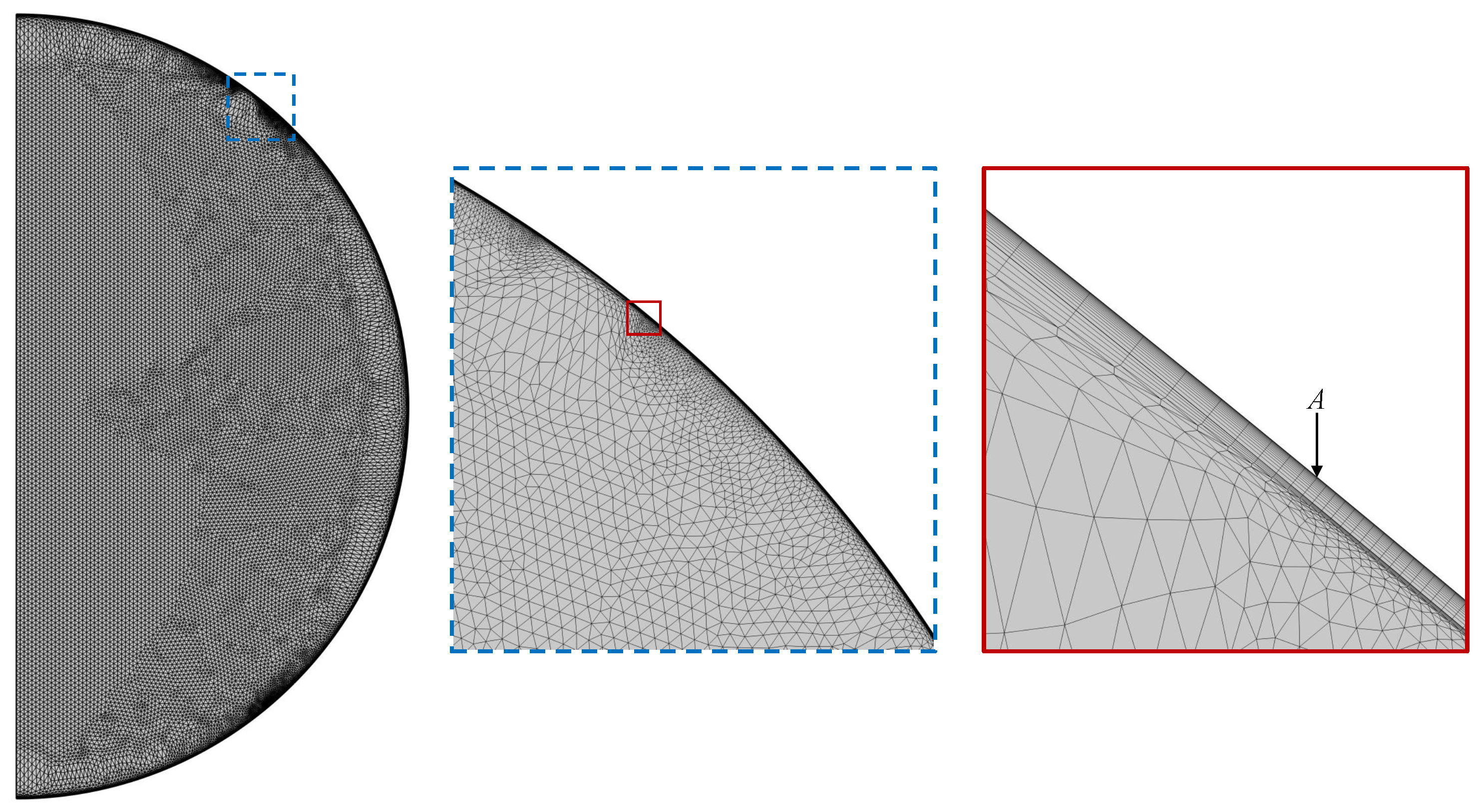
Numerical simulations were conducted using the finite element computational fluid dynamics program COMSOL Multiphysics (version 6.1) with a stationary parallel sparse direct solver. The COMSOL model solved axisymmetric bulk flow according to (1) in cylindrical coordinates with constant bulk properties and . Coupled interfacial flow was solved in spherical coordinates according to (2) with a shear-thinning viscosity of (3). The triangular mesh consisted of 62,242 bulk, 2191 boundary, and 993 surface elements. This mesh was utilized for all simulations and is shown in Figure 3 with magnified views presenting the increase in mesh fineness when approaching the air–liquid interface, corresponding to the bulk and boundary elements. Edge delineations of boundary elements within the bulk mesh match exactly with delineations of neighboring linear surface elements. The linear surface mesh, also displayed in the further zoomed view, increases in fineness exponentially when approaching the rotating ring. This increase in surface element fineness occurs at both the outer edge (displayed in Figure 3, second magnification) and inner edge of the rotating ring, as well as at at the edge of the stationary southern end-cap.
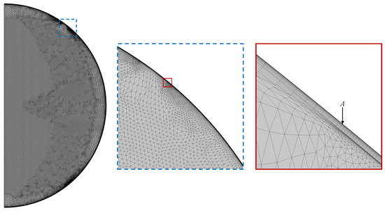
Figure 3.
Finite element mesh of the COMSOL RSD model with magnified views centered at the rotating ring’s edge A, displaying the spatial refinement near the interface.
Flow cases simulated corresponded to values of , , , and , selected based on previous sensitivity analyses [14,38], preliminary measurements of human insulin solutions [22], and RSD experiment ring rotation speeds. The resulting flow was quantified first through interfacial profiles of S, , and versus , detailing direct effects on the interface. Bulk flow effects were analyzed using azimuthal angular momentum and azimuthal vorticity , where the velocity components are in cylindrical coordinates . Fluid energetic state was investigated using viscous dissipation integrated over the total volume in cylindrical coordinates and non-dimensionalized by [14]:
3. Results
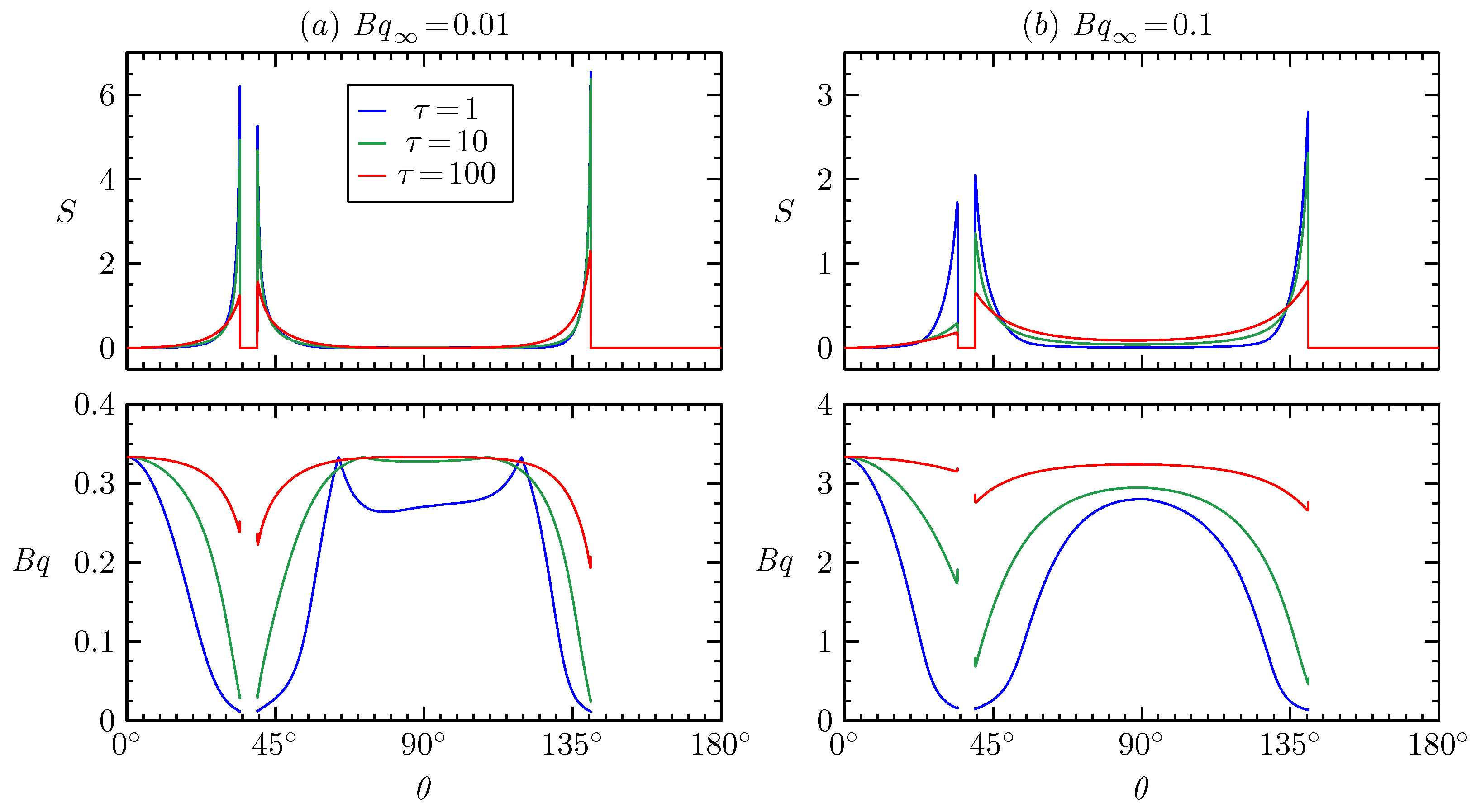
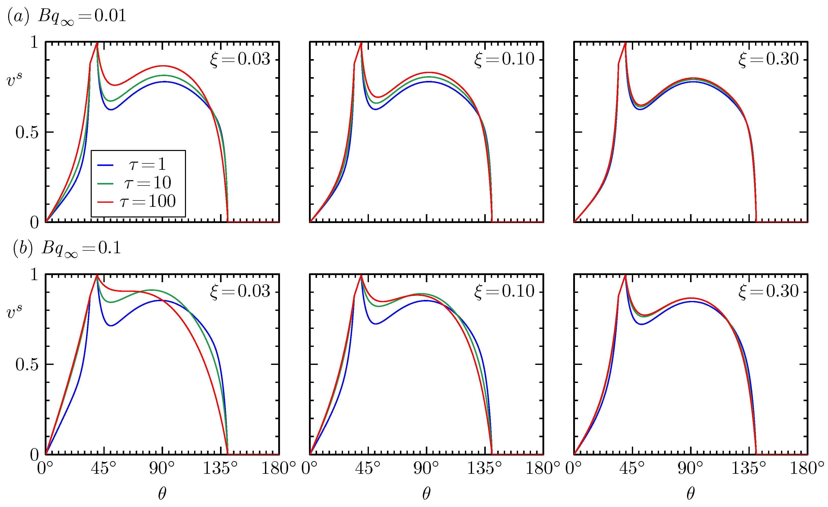
The shear-thinning constitutive model for surface shear viscosity (3) produces changes in the flow based on three model parameters (graphically presented in Figure 2): the minimum or baseline surface viscosity at infinite strain rate represented by , the surface viscosity ratio which determines maximum viscosity at zero strain rate expressed by , and the critical characteristic interfacial stress that determines the point of transition between zero- and infinite-strain-rate surface viscosities. Parametric effects of the critical-stress viscosity model were first assessed through their direct impact on the flow at the air–liquid interface. Figure 4 shows the interfacial response of (a) interfacial strain rate norm S and (b) the consequent viscous response represented by Boussinesq number to variations in two and three values with . In all flow cases, S peaks at near-edge regions, namely the edges of the rotating ring and the stationary end-cap, eclipsing strain rate magnitudes well into the shear-thinning regimes presented in Figure 2. Increasing S decreases according to (3), near-edge high S values reducing toward , with altering how readily thins. cases show complete thinning of to at these high S edge regions. Moving away from near-edge regions, most of the interface remains in the zero-strain-rate limit of high viscosity . Variation in incurs changes in interfacial flow that can be visualized using surface velocity profiles, versus , as presented in Figure 5. In general, near the rotating ring, higher values indicate higher values, with larger viscosities transmitting more force from the rotating ring to the surrounding fluid. Conversely, near the stationary end-cap, lower values indicate higher values, as larger viscosities more quickly dampen fluid motion approaching the no-slip condition at the solid boundary.
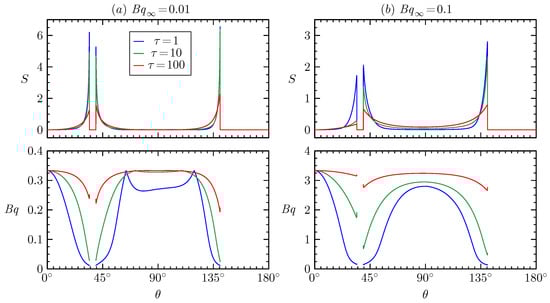
Figure 4.
Strain rate norm S and Boussinesq number versus polar angle at and with and as indicated.
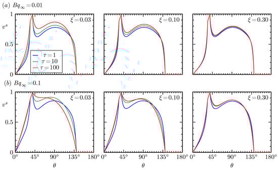
Figure 5.
Surface azimuthal velocity versus polar angle at with , , and as indicated.
The effects of model parameters , , and produce distinct responses in the profiles of Figure 5 (the first column of which contains the cases presented in Figure 4). effectively controls how non-Newtonian the interface becomes, with smaller values representing larger disparities between minimum and maximum . As increases toward unity, the effects of diminish, with little response to variation in above (becoming fully independent of when , indicating Newtonian viscosity independent of interfacial shear rate). In the other limit, as tends to zero, the fluid becomes infinitely viscous at zero strain rate, representing a Bingham fluid that resists motion until after a critical interfacial shear stress . The parameter , dictates the shear stress at which the interface transitions to flow at lower viscosity. The effects of manifest most prominently at regions of high interfacial stress, as shown by the near-edge variation in Figure 4, with large values producing interfaces dominated by large viscosities approaching the zero-strain-rate maximum . Decreasing decreases near the rotating ring and increases near the stationary end-cap as the interface thins more readily in these high-stress regions, decreasing the local as seen in Figure 4. Reducing diminishes the effects of , with little response to variation in below (becoming fully independent of when , indicating Newtonian viscosity thinning to at all stresses). Increasing both accentuates changes incurred by and and produces the increase in near the rotating ring and decrease in approaching the stationary end-cap. Combinations of small , large , and large (for example , , and ) produce high interfaces that approach the decoupled solution in the limit of with solid-body rotation within the region from the north pole to the rotating ring.
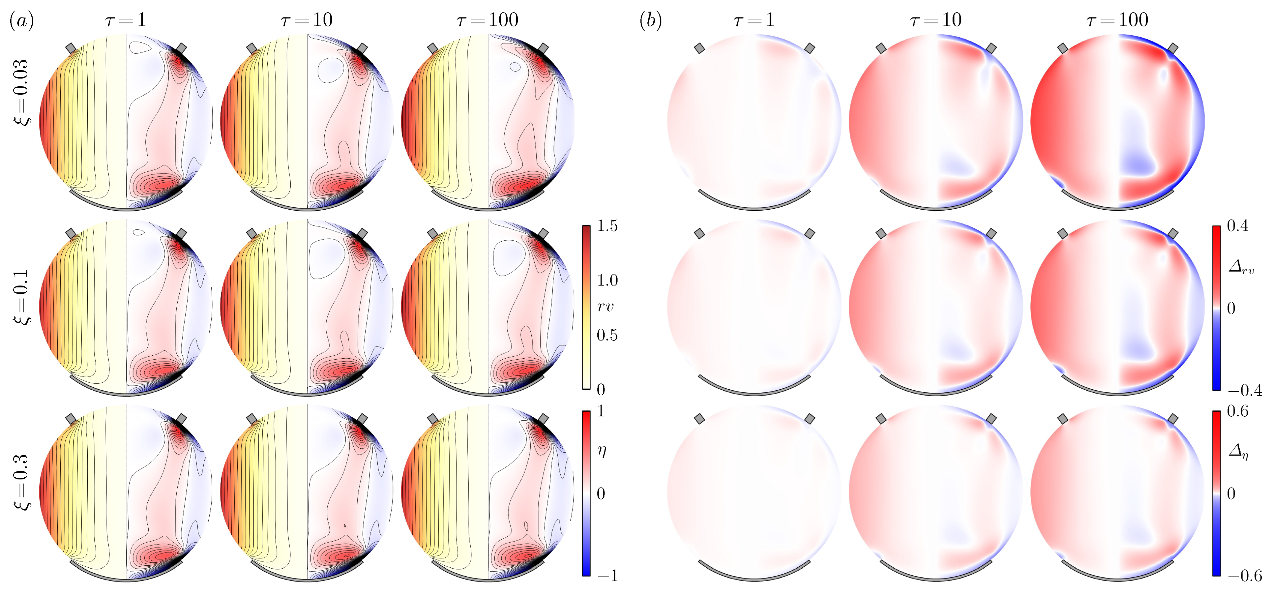
Bulk flow is only moderately affected by the interfacial parameters and . Figure 6a portrays bulk flow profiles using angular momentum in the left hemisphere ( contours representing vortex lines) and azimuthal vorticity in the right hemisphere for and , corresponding to the nine flow cases with presented in Figure 5a. Figure 6b presents the difference of each flow case from Newtonian flow at . Figure 6a flow profiles become very similar for large and small , with minimal variation observed between the five cases in the column and the row and Figure 6b showing only slight variation from Newtonian values. This similarity is a result of these flow cases varying only subtly from the already relatively small baseline interfacial excess viscosity defined by , producing flows that only subtly depart from the Newtonian interface with equivalent values depicted in Figure 1 (with and being the case closest to Newtonian). In cases with small and large , those with larger , the contours of become more tangential to the interface and the boundary layer on the rotating ring increases in size as a result of the increased interfacial flow.
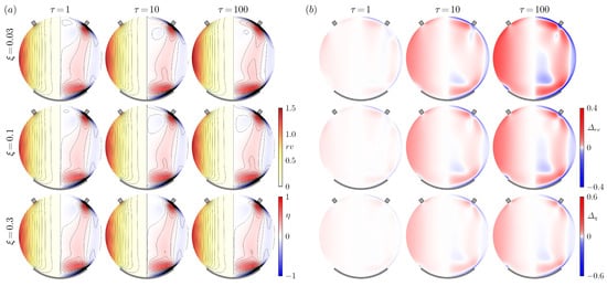
Figure 6.
(a) Angular momentum (left hemisphere) and azimuthal vorticity (right hemisphere) for and with and as indicated. (b) Difference in (left hemisphere) and (right hemisphere) from the related Newtonian flow case with constant .
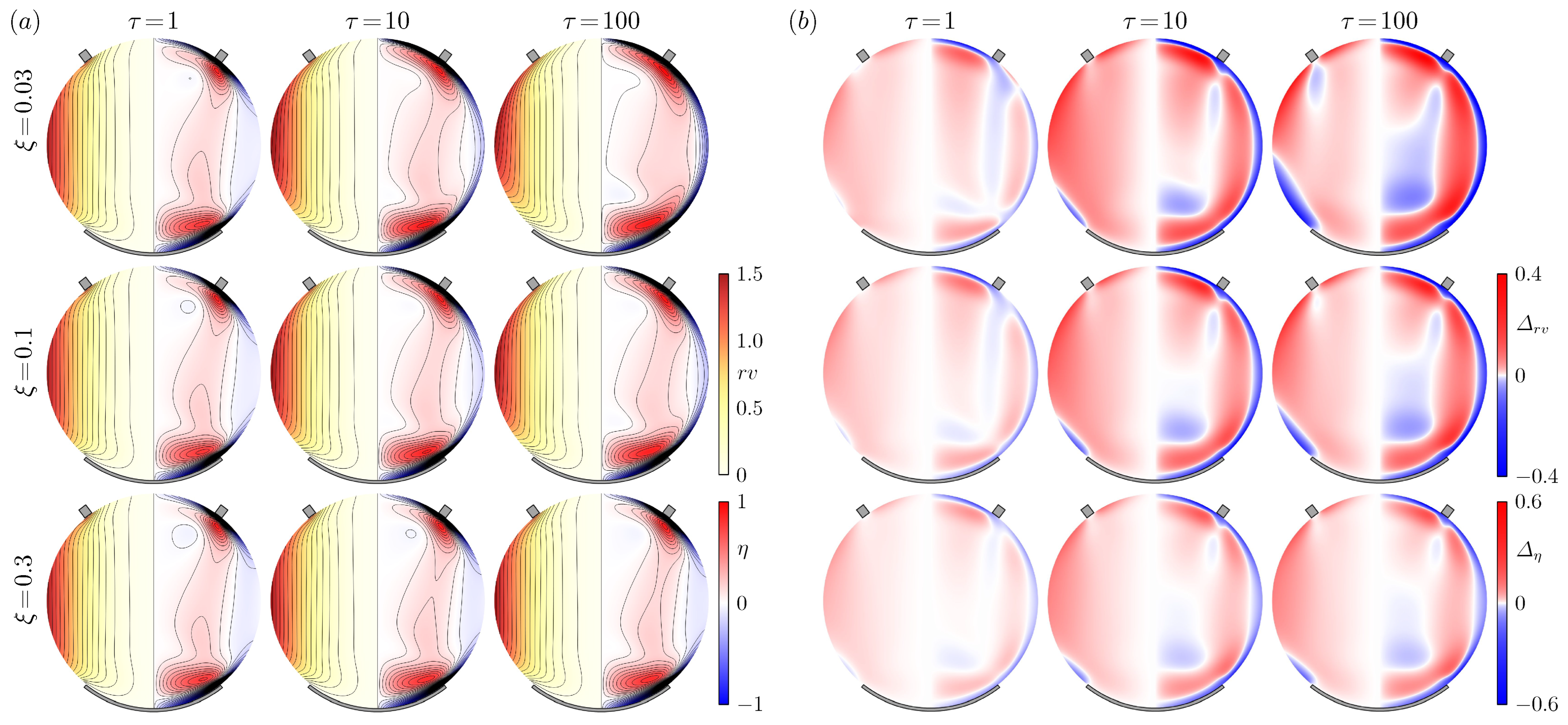
The effects of and on bulk flow become more prominent with larger values, with bulk flow, in general, being of greater magnitude due to the increased transport of momentum by the action of surface shear viscosity. Figure 7a again shows bulk flow profiles using angular momentum on the left and azimuthal vorticity on the right, for and , which corresponds to the nine flow cases with presented in Figure 5b. When , flow variation and the difference from Newtonian flow as depicted in Figure 7b remain minor; however, the bottom row at exhibits significant changes with due to the increased transport of momentum. Decreasing and increasing increases overall, with the and case approaching the decoupled solution, depicting near solid-body rotation from the north pole to the rotating ring. The variability in bulk flow observed, ranging between Newtonian and decoupled solutions, allows this shear-thinning interfacial viscosity model to match particle-tracking velocimetry measurements (as detailed in [17]) performed on the 2 mg/mL case presented in Figure 1a. However, comparison between experimental and computed flows results in solutions that are non-unique. The ability to fit experimental measurements verifies that this interfacial viscosity model can capture interfacial behavior. Model validation requires measurements of fluid rheological properties and behavior using precision flow systems such as deep-channel or knife-edge viscometers.
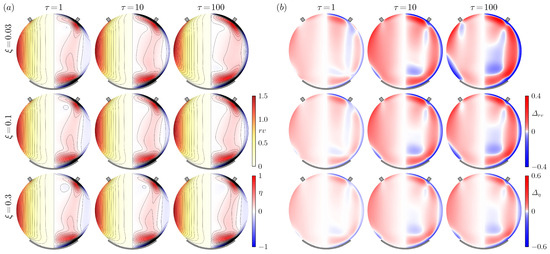
Figure 7.
(a) Angular momentum (left hemisphere) and azimuthal vorticity (right hemisphere) for and with and as indicated. (b) Difference in (left hemisphere) and (right hemisphere) from the related Newtonian flow case with constant .
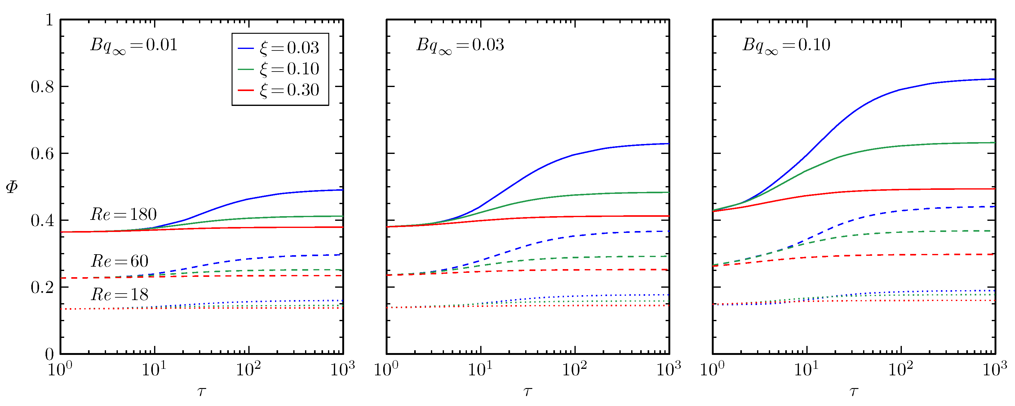
The total viscous dissipation integrated over the fluid volume represents the rate of kinetic energy dissipated by the action of viscosity. As such, increases with increasing viscosity, a trend also applicable to interfacial viscosity. Figure 8 displays the variation of in response to , , , and . increases monotonically with increasing , with the minimum interfacial viscosity raising all subsequent values possible and increasing overall resistance to flow. Dissipation increases monotonically with increasing , with higher flow speeds resulting in greater transmission of kinetic energy by the rotating ring with larger strain rates S, incurring larger viscous forces. Furthermore, can be interpreted as a measure of length scale. As the drop increases in size, the length scale associated with increases, thereby resulting in a monotonic relation between and drop size at a consistent rotation rate . The larger the drop, the higher the and the lower the baseline at infinite-shear-rate (as this quantity has length scale in the denominator), altering the degree of coupling between the air–liquid interface and the bulk fluid. This trend is observable in , as decreasing decreases coupling, which is observable through decreased dependence on interfacial parameters. In most cases, decreasing and increasing increase , with each of these changes resulting in increased : by increasing the maximum near-zero strain rate and by increasing the portion of the interface that remains unthinned. However, this trend is not universal as certain combinations of and at particular and values, such as the region of at , , and , where the combination of parameters produce lower values and consequentially lower values compared to the and 0.30 cases. In total, any combination of constitutive parameters that increases viscosity, or that increases S, will increase the total dissipation of the system.
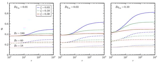
Figure 8.
Viscous dissipation versus characteristic interfacial stress , with , , and (solid, dashed, or dotted lines) as indicated.
4. Discussion
The response of the air–liquid interface to model parameters ( versus in Figure 5) demonstrated an expected dependence on model parameters. Shear-thinning model effects on range from Newtonian viscous to decoupled interfaces, exhibiting highest sensitivity within certain intermediate parameter regimes of and with increases in baseline increasing parametric effects. Notably, effective parameter regimes are modulated by differing flow states, as demonstrated by decreases in decreasing sensitivity to , , and . These regimes are promising for the modeling of complex fluids and the ability to utilize parameter measurements from ground-based systems to predict hydrodynamics in microgravity. Further tuning flow regimes, through controllable parameters such as , can allow for the identification of sensitive regimes for the investigation of constituent behavior. Notably, caution must be exercised in the interpretation of interfacial velocimetry results and their rheological use, as in specific flow regimes, different combinations of model parameters can produce similar profiles, especially when nearing the edges of effectual parameter ranges.
While all cases remain at least weakly coupled to the bulk flow, this parametric investigation establishes the effectual ranges of model parameters. Bulk flow profiles in Figure 6 and Figure 7 demonstrate the moderate sensitivity of the bulk flow to the behavior of the air–liquid interface, which generally increases with higher values while maintaining interface to bulk flow coupling. Furthermore, an investigation of (Figure 8) may be useful for gauging the interchange between the hydrodynamics and energetics of flow constituents. The change in by the shear-thinning model is indicative of a change in structure of a constituent material. As such, changes in the shape of a constituent of a complex fluid induced by flow are reciprocal with the changes that manifest in flow behavior. Describing the stability of such reciprocal changes could lead to a better understanding of natural systems as well as improved control of transport phenomena.
A major purpose of this investigation was to support future work in non-Newtonian modeling of complex fluids. Verification in the current study produces the foundation for future model validation, which would require experimentation in other systems, such as deep-channel and knife-edge viscometers, with greater measurement accuracy for more precise model parameter estimates. A subsequent natural extension is to include a non-Newtonian model for bulk shear viscosity, as many complex fluids also incur constitutive changes far from the interface. Such an investigation would allow for the examination of both similar and dissimilar viscosity constitutive relations for the interface and bulk, synergizing well with both empirical or theoretical constitutive model development. An essential aspect of such model development is a verification–validation–prediction process, where computational models are first verified as functional through fitting to experimental measurements, obtaining model parameters in the process. Models would then be validated by matching computational models with measured parameters to experimental measurements in complementary geometries and or flow regimes. Upon successful validation, such computational models could then have their predictive capability tested in applied and theoretical settings of interest. Such a process has the potential to enable the testing of theoretically developed first-principle constitutive models for fluid viscosity.
5. Conclusions
This investigation assessed the sensitivity of a generalized Newtonian shear-thinning model for surface shear viscosity when applied to protein solution hydrodynamics. The flow consisted of a spherical, non-Newtonian air–liquid interface using the generalized Boussinesq–Scriven interfacial model coupled to a Newtonian bulk fluid. The hypothesis evaluated was that if an interface exhibits non-Newtonian surface shear viscosity, then coupled system-wide flow will be a function of interfacial parameters. A specific parameter regime was identified ( and ) where this hypothesis held. Increases in baseline interfacial viscosity (before the decoupling limit of ) or increase in flow speed increased coupling between the interface and bulk, which resulted in increased parametric sensitivity. This preliminary verification enables future model validation through corroborative measurements of protein solution behavior using precision flow devices.
Author Contributions
Conceptualization, J.A.A., F.P.R., J.M.L. and A.H.H.; methodology, J.A.A. and F.P.R.; software, J.A.A. and F.P.R.; validation, J.A.A. and F.P.R.; formal analysis, J.A.A. and F.P.R.; investigation, J.A.A. and F.P.R.; resources, J.A.A. and F.P.R.; data curation, J.A.A. and F.P.R.; writing—original draft preparation, J.A.A.; writing—review and editing, J.A.A., F.P.R., J.M.L., P.T.U. and A.H.H.; visualization, J.A.A. and J.M.L.; supervision, J.A.A., P.T.U., J.M.L. and A.H.H.; project administration, J.A.A. and A.H.H.; funding acquisition, J.A.A., J.M.L., P.T.U. and A.H.H. All authors have read and agreed to the published version of the manuscript.
Funding
This research was funded by NSF grants 1929134, 1929139, 2204081, 2204082, and 2323020.
Data Availability Statement
COMSOL code available upon request. ISS data is on NASA’s Physical Sciences Informatics system: https://psi.ndc.nasa.gov/app/record/197482 (accessed on 23 February 2025).
Acknowledgments
The authors thank members from NASA; the ISS National Lab; Teledyne–Brown Eng., including Byron Bonds, Fran Chiaramonte, Kevin Depew, Shawn Fann, Paul Galloway, Sridhar Gorti, Michael Hall, Louise Littles, James McClellan, Ben Murphy, Heidi Parris, Shawn Reagan, Ryan Reeves, Shawn Stephens, and Hong Q. Yang for their support of the RSD project. The authors also thank astronauts Raja Chari, Shane Kimbrough, Christina Koch, Akihiko Hoshide, Megan McArthur, Luca Parmitano, Thomas Pasquet, and Mark Vande Hei for their excellence and flexibility in real-time operations. The authors are also grateful for support from NASA BPS, NASA MSFC, NASA JSC, NASA HQ, NSF–CASIS, the ISS National Lab, Boeing, and Teledyne–Brown Eng.
Conflicts of Interest
The authors declare no conflicts of interest.
References
- Ethier, C.R.; Simmons, C.A. Introductory Biomechanics: From Cells to Organisms; Cambridge University Press: Cambridge, UK, 2007; pp. 288–293. [Google Scholar]
- Jenkinson, I.R.; Seuront, L.; Ding, H.; Elias, F. Biological Modification of Mechanical Properties of the Sea Surface Microlayer, Influencing Waves, Ripples, Foam and Air-Sea Fluxes. Elem. Sci. Anthr. 2018, 6, 26. [Google Scholar] [CrossRef]
- Murr, L.E.; Johnson, W.L. 3D Metal Droplet Printing Development and Advanced Materials Additive Manufacturing. J. Mater. Res. Technol. 2017, 6, 77–89. [Google Scholar] [CrossRef]
- Gilani, N.; Aboulkhair, N.; Simonelli, M.; East, M.; Ashcroft, I.; Hague, R. Insights into Drop-on-Demand Metal Additive Manufacturing through an Integrated Experimental and Computational Study. Addit. Manuf. 2021, 48, 102402. [Google Scholar] [CrossRef]
- Li, J.; Krause, M.E.; Chen, X.; Cheng, Y.; Dai, W.; Hill, J.J.; Huang, M.; Jordan, S.; LaCasse, D.; Narhi, L.; et al. Interfacial Stress in the Development of Biologics: Fundamental Understanding, Current Practice, and Future Perspective. AAPS J. 2019, 21, 44. [Google Scholar] [CrossRef] [PubMed]
- Morrison, F.A. Understanding Rheology; Topics in Chemical Engineering; Oxford University Press: New York, NY, USA, 2001; pp. 1–11, 228–232. [Google Scholar]
- Dill, K.A.; Bromberg, S. Molecular Driving Forces: Statistical Thermodynamics in Biology, Chemistry, Physics, and Nanoscience, 2nd ed.; Garland Science: London, UK; New York, NY, USA, 2011; pp. 29–37, 363–380, 490–502. [Google Scholar]
- Otzen, D.E. (Ed.) Amyloid Fibrils ad Prefibrillar Aggregates; Wiley-VCH: Weinheim, Germany, 2013; pp. 151–163, 298–314. [Google Scholar]
- Adamson, A.W.; Gast, A.P. Physical Chemistry of Surfaces, 6th ed.; John Wiley and Sons Inc.: New York, NY, USA, 1997; pp. 537–551. [Google Scholar]
- Edwards, D.A.; Brenner, H.; Wasan, D.T. Interfacial Transport Processes and Rheology; Butterworth-Heinemann Series in Chemical Engineering; Butterworth-Heinemann: Stonheam, MA, USA, 1991; pp. 109–119. [Google Scholar]
- Finn, R. Capillary Surface Interfaces. Not. Am. Math. Soc. 1999, 46, 770–781. [Google Scholar]
- Gulati, S.; Raghunandan, A.; Rasheed, F.; McBride, S.A.; Hirsa, A.H. Ring-Sheared Drop (RSD): Microgravity Module for Containerless Flow Studies. Microgravity Sci. Technol. 2017, 29, 81–89. [Google Scholar] [CrossRef]
- Gulati, S.; Riley, F.P.; Lopez, J.M.; Hirsa, A.H. Mixing within Drops via Surface Shear Viscosity. Int. J. Heat Mass Transf. 2018, 125, 559–568. [Google Scholar] [CrossRef]
- Gulati, S.; Riley, F.P.; Hirsa, A.H.; Lopez, J.M. Flow in a Containerless Liquid System: Ring-sheared Drop with Finite Surface Shear Viscosity. Phys. Rev. Fluids 2019, 4, 044006. [Google Scholar] [CrossRef]
- Riley, F.P.; McMackin, P.M.; Lopez, J.M.; Hirsa, A.H. Flow in a Ring-Sheared Drop: Drop Deformation. Phys. Fluids 2021, 33, 042117. [Google Scholar] [CrossRef]
- McMackin, P.M.; Griffin, S.R.; Riley, F.P.; Gulati, S.; Debono, N.E.; Raghunandan, A.; Lopez, J.M.; Hirsa, A.H. Simulated Microgravity in the Ring-Sheared Drop. npj Microgravity 2020, 6, 2. [Google Scholar] [CrossRef]
- McMackin, P.M.; Adam, J.A.; Riley, F.P.; Hirsa, A.H. Single-Camera PTV within Interfacially Sheared Drops in Microgravity. Exp. Fluids 2023, 64, 154. [Google Scholar] [CrossRef]
- McMackin, P.; Adam, J.; Griffin, S.; Hirsa, A. Amyloidogenesis via Interfacial Shear in a Containerless Biochemical Reactor Aboard the International Space Station. npj Microgravity 2022, 8, 41. [Google Scholar] [CrossRef] [PubMed]
- Schleeger, M.; vandenAkker, C.C.; Deckert-Gaudig, T.; Deckert, V.; Velikov, K.P.; Koenderink, G.; Bonn, M. Amyloids: From Molecular Structure to Mechanical Properties. Polymer 2013, 54, 2473–2488. [Google Scholar] [CrossRef]
- McBride, S.A.; Tilger, C.F.; Sanford, S.P.; Tessier, P.M.; Hirsa, A.H. Comparison of Human and Bovine Insulin Amyloidogenesis under Uniform Shear. J. Phys. Chem. B 2015, 119, 10426–10433. [Google Scholar] [CrossRef] [PubMed]
- McBride, S.A.; Sanford, S.P.; Lopez, J.M.; Hirsa, A.H. Shear-Induced Amyloid Fibrillization: The Role of Inertia. Soft Matter 2016, 12, 3461–3467. [Google Scholar] [CrossRef] [PubMed]
- Balaraj, V.S.; Zeng, P.C.H.; Sanford, S.P.; McBride, S.A.; Raghunandan, A.; Lopez, J.M.; Hirsa, A.H. Surface Shear Viscosity as a Macroscopic Probe of Amyloid Fibril Formation at a Fluid Interface. Soft Matter 2017, 13, 1780–1787. [Google Scholar] [CrossRef] [PubMed]
- Adam, J.A.; Middlestead, H.R.; Debono, N.E.; Hirsa, A.H. Effects of Shear Rate and Protein Concentration on Amyloidogenesis via Interfacial Shear. J. Phys. Chem. B 2021, 125, 10355–10363. [Google Scholar] [CrossRef] [PubMed]
- Trumbore, C.N. Shear-Induced Amyloid Formation of IDPs in the Brain. In Progress in Molecular Biology and Translational Science; Elsevier: Cambridge, MA, USA, 2019; Volume 166, pp. 225–309. [Google Scholar]
- Murphy, M.P.; LeVine, H. Alzheimer’s Disease and the Amyloid-β Peptide. J. Alzheimer’s Dis. 2010, 19, 311–323. [Google Scholar] [CrossRef]
- Nizynski, B.; Dzwolak, W.; Nieznanski, K. Amyloidogenesis of Tau Protein. Protein Sci. 2017, 26, 2126–2150. [Google Scholar] [CrossRef] [PubMed]
- Araki, K.; Yagi, N.; Aoyama, K.; Choong, C.J.; Hayakawa, H.; Fujimura, H.; Nagai, Y.; Goto, Y.; Mochizuki, H. Parkinson’s Disease Is a Type of Amyloidosis Featuring Accumulation of Amyloid Fibrils of α-Synuclein. Proc. Natl. Acad. Sci. USA 2019, 116, 17963–17969. [Google Scholar] [CrossRef]
- Hull, R.L.; Westermark, G.T.; Westermark, P.; Kahn, S.E. Islet Amyloid: A Critical Entity in the Pathogenesis of Type 2 Diabetes. J. Clin. Endocrinol. Metab. 2004, 89, 3629–3643. [Google Scholar] [CrossRef]
- Ghetti, B.; Piccardo, P.; Frangione, B.; Bugiani, O.; Giaccone, G.; Young, K.; Prelli, F.; Farlow, M.R.; Dlouhy, S.R.; Tagliavini, F. Prion Protein Amyloidosis. Brain Pathol. 1996, 6, 127–145. [Google Scholar] [CrossRef] [PubMed]
- Adam, J.A.; Gulati, S.; Hirsa, A.H.; Bonocora, R.P. Growth of Microorganisms in an Interfacially Driven Space Bioreactor Analog. npj Microgravity 2020, 6, 11. [Google Scholar] [CrossRef] [PubMed]
- Slattery, J.C.; Sagis, L.M.; Oh, E.S. Interfacial Transport Phenomena, 2nd ed.; Springer: New York, NY, USA, 2007; pp. 358–361. [Google Scholar]
- Patouillet, K.; Davoust, L.; Doche, O.; Delacroix, J. Mannheimer and Schechter Model Revisited: Viscosimetry of a (Non-) Newtonian and Curved Interface. Phys. Rev. Fluids 2019, 4, 054002. [Google Scholar] [CrossRef]
- Sharma, V.; Jaishankar, A.; Wang, Y.C.; McKinley, G.H. Rheology of globular proteins: Apparent yield stress, high shear rate viscosity and interfacial viscoelasticity of bovine serum albumin solutions. Soft Matter 2011, 7, 5150–5160. [Google Scholar] [CrossRef]
- Gudapati, H.; Parisi, D.; Colby, R.H.; Ozbolat, I.T. Rheological investigation of collagen, fibrinogen, and thrombin solutions for drop-on-demand 3D bioprinting. Soft Matter 2020, 16, 10506–10517. [Google Scholar] [CrossRef] [PubMed]
- Yang, J.; Yu, K.; Tsuji, T.; Jha, R.; Zuo, Y.Y. Determining the Surface Dilational Rheology of Surfactant and Protein Films with a Droplet Waveform Generator. J. Colloid Interface Sci. 2019, 537, 547–553. [Google Scholar] [CrossRef] [PubMed]
- McPherson, A.; DeLucas, L.J. Microgravity Protein Crystallization. npj Microgravity 2015, 1, 1–20. [Google Scholar] [CrossRef] [PubMed]
- Riccobelli, D.; Al-Terke, H.H.; Laaksonen, P.; Metrangolo, P.; Paananen, A.; Ras, R.H.A.; Ciarletta, P.; Vella, D. Flattened and Wrinkled Encapsulated Droplets: Shape Morphing Induced by Gravity and Evaporation. Phys. Rev. Lett. 2023, 130, 218202. [Google Scholar] [CrossRef] [PubMed]
- Underhill, P.T.; Hirsa, A.H.; Lopez, J.M. Modelling Steady Shear Flows of Newtonian Liquids with Non-Newtonian Interfaces. J. Fluid Mech. 2017, 814, 5–23. [Google Scholar] [CrossRef]
- Bird, R.B.; Armstrong, R.C.; Hassager, O. Dynamics of Polymeric Liquids Volume One Fluid Mechanics, 2nd ed.; John Wiley and Sons Inc.: New York, NY, USA, 1987; pp. 227–228. [Google Scholar]
- Doi, M. Soft Matter Physics, 1st ed.; Oxford University Press: Oxford, UK, 2013; pp. 166–171. [Google Scholar]
Disclaimer/Publisher’s Note: The statements, opinions and data contained in all publications are solely those of the individual author(s) and contributor(s) and not of MDPI and/or the editor(s). MDPI and/or the editor(s) disclaim responsibility for any injury to people or property resulting from any ideas, methods, instructions or products referred to in the content. |
© 2025 by the authors. Licensee MDPI, Basel, Switzerland. This article is an open access article distributed under the terms and conditions of the Creative Commons Attribution (CC BY) license (https://creativecommons.org/licenses/by/4.0/).