Abstract
This paper investigates the design methodologies of pure rolling helical gear pumps with various tooth profiles, based on the active design of meshing lines. The transverse active tooth profile of a pure rolling helical gear end face is composed of various function curves at key control points. The entire transverse tooth profile consists of the active tooth profile and the Hermite curve as the tooth root transition, seamlessly connecting at the designated control points. The tooth surface is created by sweeping the entire transverse tooth profile along the pure rolling contact curves. The fundamental design parameters, tooth profile equations, tooth surface equations, and a two-dimensional fluid model for pure rolling helical gears were established. The pressure pulsation characteristics of pure rolling helical gear pumps and CBB-40 involute spur gear pumps, each with different tooth profiles, were compared under specific working pressures. This comparison encompassed the maximum effective positive and negative pressures within the meshing region, pressure fluctuations at the midpoints of both inlet and outlet pressures, and pressure fluctuations at the rear sections of the inlet and outlet pressures. The results indicated that the proposed pure rolling helical gear pump with a parabolic tooth profile exhibited 42.81% lower effective positive pressure in the meshing region compared to the involute spur gear pump, while the maximum effective negative pressure was approximately 27 times smaller than that of the involute gear pump. Specifically, the pressure pulsations in the middle and rear regions of the inlet and outlet pressure zones were reduced by 33.1%, 6.33%, 57.27%, and 69.61%, respectively, compared to the involute spur gear pump.
1. Introduction
An involute external gear pump has features such as a simple structure, easy manufacturing, reliable operation, and strong self-priming ability, making it widely used in various industrial applications. However, traditional involute external gear pumps experience oil trapping during operation. The reason for this is that during the normal operation of a traditional involute external gear pump, the next pair of gears begins to engage before the previous pair of gears has disengaged. This causes a portion of the oil to be trapped in the enclosed space formed in the gear meshing area. As the gears rotate, the enclosed volume first decreases and then increases. When the enclosed volume decreases, the oil is compressed and extruded through the gaps, generating high pressure. When the enclosed volume increases, it creates a local vacuum, resulting in negative pressure. These phenomena cause the gear pump to produce vibration, noise, and cavitation, thereby reducing its performance and lifespan [1].
Many scholars have conducted theoretical, simulation, and experimental analyses on external involute gear pumps, including the following: theoretical analysis of the variation law of trapped oil volume in external involute gear pumps [2,3], simulation analysis of cavitation phenomena in gear pumps [4,5,6], simulation analysis of trapped oil regions [7,8], impact of temperature and rotational speed variations on pressure [9,10], and changes in flow rate and pressure in gear pumps [11]. To further enhance the performance of gear pumps, many scholars have proposed different solutions to the oil-trapping issue, such as creating unloading grooves on the pump body and conducting precise numerical simulation analyses of the unloading groove area [12,13], designing a helical gear pump with a double circular arc composite tooth profile [14,15,16,17,18], and setting the end-face contact ratio conditions for helical gear pumps [19]. In recent years, a novel point contact transmission mechanism known as a “line gear” has been introduced [20]. It achieves gear meshing via a pair of conjugate spatial curves. Depending on specific transmission requirements, different variants have been developed, including planar line gears, parallel-axis circular arc line gears, crossed-axis line gears, and concave–convex arc line gears [21,22,23,24]. Among these, the parallel-axis external meshing line gear is characterized by having a small number of teeth and an end-face contact ratio of zero. Consequently, during meshing, its tooth surfaces do not combine with the two end faces to form a sealed volume. Chen et al. proposed a pure rolling gear and rack design method based on the active design of meshing line parametric equations. This pure rolling gear has a zero end-face contact ratio during meshing, which theoretically can greatly improve the oil-trapping phenomenon [25,26,27]. Chen et al. proposed a pure rolling curved cylindrical gear design method based on the active design of meshing line functions. Curved cylindrical gears are designed by forming composite tooth profiles from different curve functions controlled by key points of the tooth profile and by predefining meshing line equations [28]. These gears also have zero face contact ratio.
This paper proposes a design of pure rolling cylindrical helical gear pumps with different tooth profiles. The gear pump consists of a pair of pure rolling helical gears. By using key control points on the tooth profile to control different functional curves as the end-face working tooth profiles of the pure rolling helical gears, and employing Hermite curves as the tooth root transition curves, the tooth surface parametric equations were derived. Basic design parameters were determined and a mathematical model was established to study the pressure pulsations at set monitoring points for pure rolling helical gear pumps with different tooth profiles. The performance was then compared with that of the CBB-40 involute spur gear pump.
2. Active Design of Meshing Line Parametric Equations for Pure Rolling Circular Arc Tooth Lines
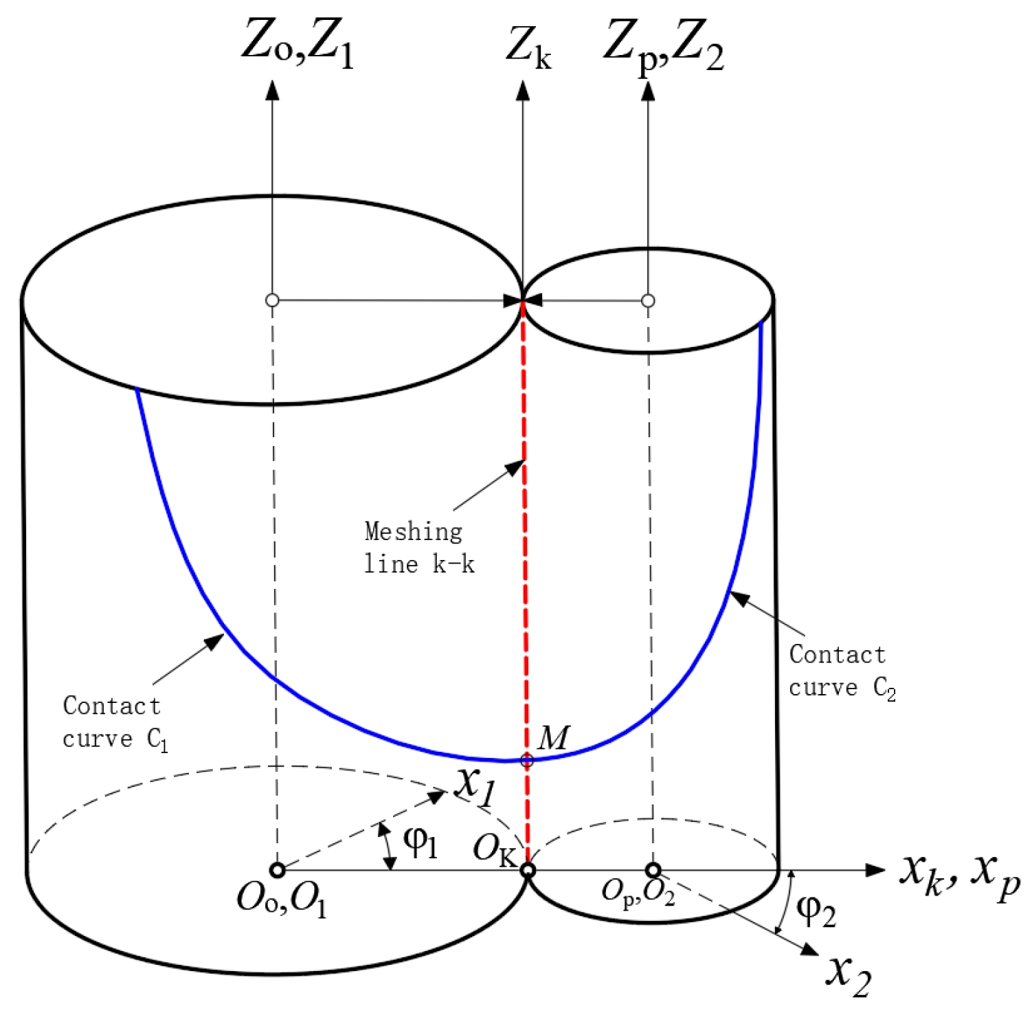
Figure 1 shows the meshing coordinate system of pure rolling cylindrical helical gears, where the meshing line and the contact line are marked in red and blue, respectively. Coordinate systems , were fixedly connected to the frame. The coordinate system represents the motion law of the meshing point of the pure rolling helical gear, and this coordinate system was fixedly attached to the frame. The coordinate systems , were fixedly connected to the driving gear and the driven gear, respectively. At the beginning of meshing, coincides with , and coincides with . The distance between the two rotational axes and is a. The angular velocities of the driving gear and the driven gear are and , respectively, and their rotation angles are and , respectively. When the driving gear rotates counterclockwise at a constant angular velocity , the meshing point moves upward uniformly along the axis . At this time, the meshing point forms the meshing line in the coordinate system , Simultaneously, tooth surface contact lines and are formed on the pitch cylinders of the driving gear and the driven gear, respectively.
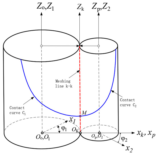
Figure 1.
Coordinate systems for the design of pure rolling cylindrical gears.
According to the detailed description of this curve in [9,10], specifically, the movement of the meshing point along the meshing line , the parametric equations of the uniform motion law for point are the following:
where is the coefficient in the parametric equation of the motion of the meshing point , and is the motion parameter.
The relationship between the rotation angles of the driving gear and the driven gear is
where represents the motion’s proportional coefficient used to express the relationship between the rotation angle and the parameter , and is the transmission ratio.
Given that the coordinate system was fixed to the frame, and the coordinate system was fixed to the driving gear, the transformation matrix from to is
Similarly, given that the coordinate system was fixed to the frame, and the coordinate system was fixed to the driving gear, the transformation matrix from to is
The coordinate transformation equations for the meshing point from the coordinate system to the coordinate systems of the driving gear and the driven gear are shown in Equations (5) and (6):
The coordinate transformation matrix between coordinate systems and is
By substituting Equations (1) and (2) into Equations (5) and (6) respectively, the parametric equations of the contact curves on the driving and driven tooth surfaces of the pinion and the gear can be, respectively, expressed as functions of the motion parameter in Equations (8) and (9).
where is the variable parameter of the helical line on the pitch cylinder, , .
3. Mathematical Models of Different End-Face Tooth Profiles for Pure Rolling Helical Gears
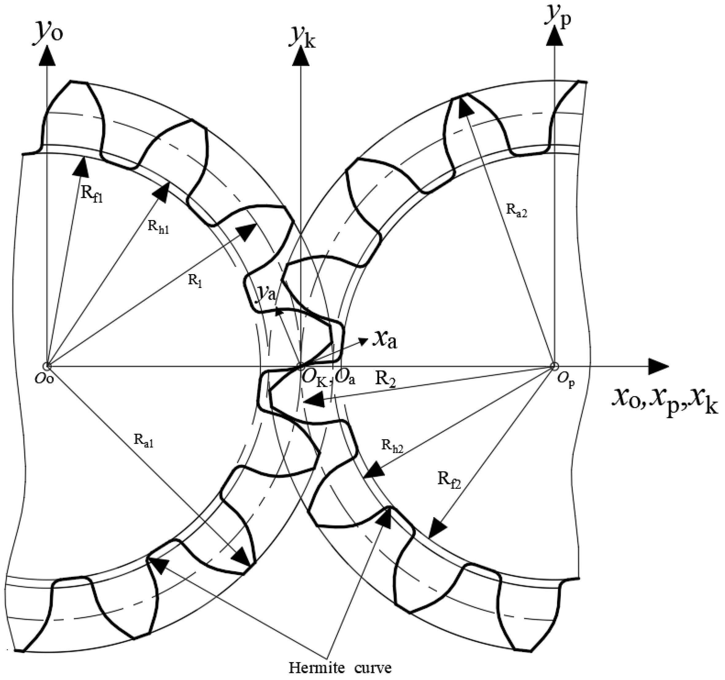
In this study, both the driving gear and the driven gear of the pure rolling helical gear pump had convex tooth profiles on their end faces, and the type of end-face meshing was convex–convex meshing. A schematic diagram of the gear end face is shown in Figure 2, where represents the center of the driving gear, represents the center of the driven gear, and denotes the end-face pressure angle.
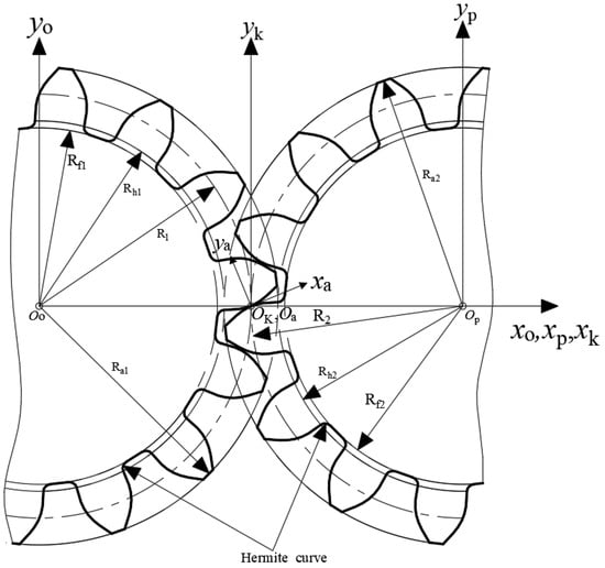
Figure 2.
The tooth profile of the driving and driven wheel end faces.
As shown in Figure 2, the transition fillets of both the driving gear and the driven gear utilize Hermite curves. This curve can adjust its shape through simple parameters to effectively enhance the bending strength of the tooth root.
To avoid interference between the tooth profiles of the two gears, the curvature radius of the pure rolling helical gear’s tooth profile at the meshing point is smaller than that of the involute at point . This type of pure rolling helical gear tooth profile only contacts at node M, achieving pure rolling meshing.
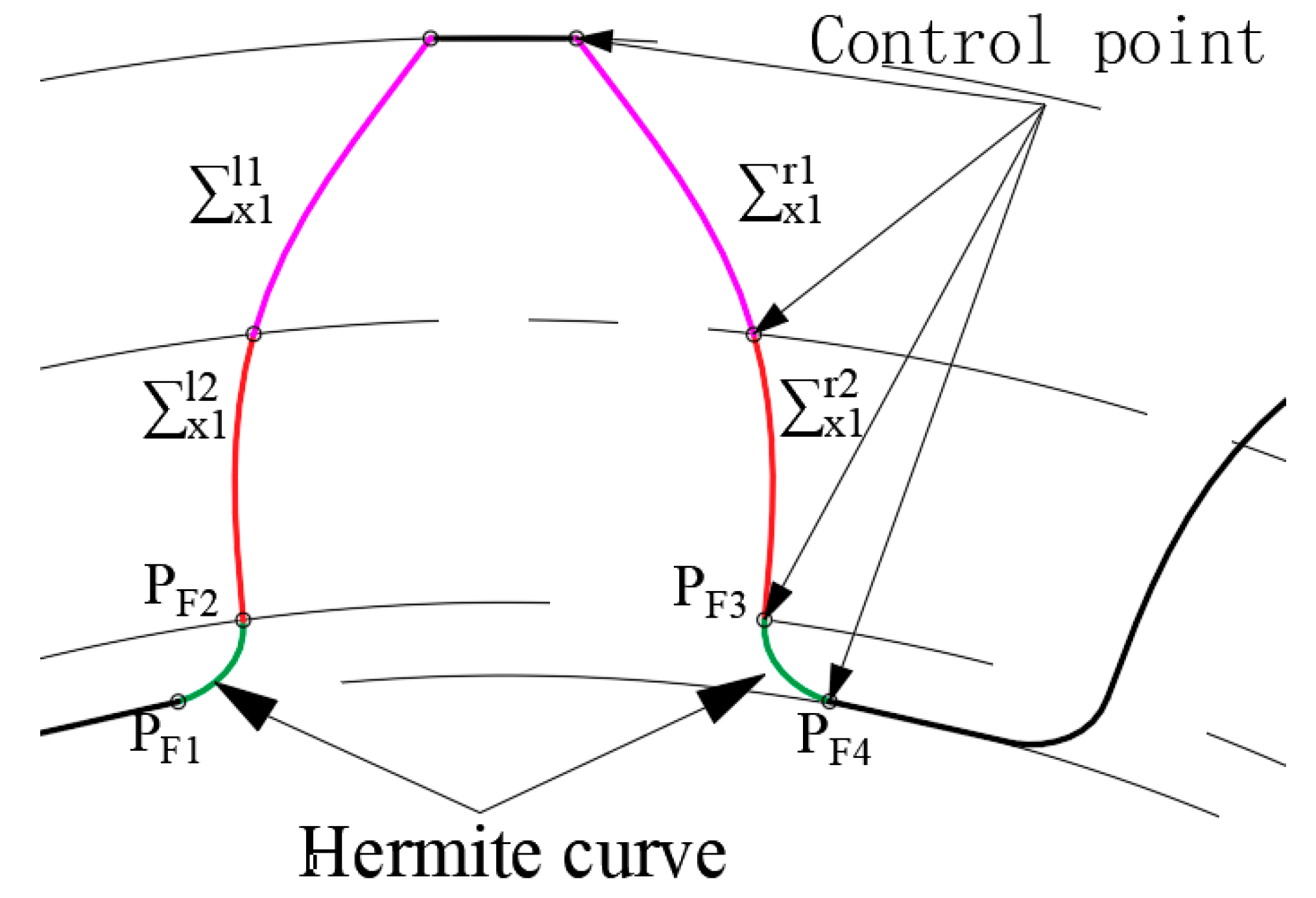
The right-side tooth root transition curve of the driving gear is composed of a Hermite curve, where the right-side Hermite points of the driving gear are and . Both points are located on the driving gear’s transition circle . Point is formed by the intersection of the driving gear’s transition circle and the tooth profile curve. Point is formed by a line passing through with a slope of 1 intersecting the root circle . Similarly, the right-side tooth root transition curve of the driven gear also uses a Hermite curve and was obtained through the above method.
As shown in Figure 3, and represent the parametric equations of the left and right sides of the tooth profile, where the superscripts and denote the left and right tooth profiles, respectively. The superscript indicates the position of a single tooth profile or a composite tooth profile curve. Specifically, when , the tooth profile curve is located at the upper end of the tooth profile; when, the tooth profile curve is at the lower end; and when , the tooth profile curve represents a single tooth profile curve. The subscript represents the abbreviation of the tooth profile function curve in English, while the subscript denotes the driving or driven gear, where corresponds to the driving gear, andcorresponds to the driven gear.

Figure 3.
Sketch of the entire transverse tooth profiles and control points.
3.1. Mathematical Model of the End-Face Hyperbolic Cosine Tooth Profile for Pure Rolling Helical Gears
According to Figure 3, the parametric equation of the right-side hyperbolic cosine tooth profile of the driving gear is expressed by Equation (10) as the following:
In the equation, represents the hyperbolic cosine tooth profile curve of the driving gear, indicates the right side of the hyperbolic cosine tooth profile curve, denotes the parametric value of the hyperbolic cosine function for the driving gear, and represents the tooth profile parameter of the hyperbolic cosine function.
According to Figure 3, the parametric equation of the right-side hyperbolic cosine tooth profile curve of the driven gear is expressed by Equation (11) as the following:
3.2. Mathematical Model of the Parabolic Tooth Profile for the End Face of Pure Rolling Helical Gears
According to Figure 3, the parametric equation of the right-side parabolic tooth profile curve of the driving gear is expressed by Equation (12) as the following:
In the formula, represents the parabolic tooth profile curve of the driving gear; indicates the right side of the parabolic tooth profile curve; is the parametric value of the parabolic function for the driving gear; and is the tooth profile parameter of the parabolic function.
Similarly, according to Figure 3, the parametric equation of the right-side parabolic tooth profile of the driven gear is expressed by Equation (13) as the following:
3.3. Mathematical Model of the Cycloidal and Hyperbolic Cosine Composite Tooth Profile Curve for the End Face of Pure Rolling Helical Gears
According to Figure 3, the parametric equation of the right-side cycloidal tooth profile curve of the driving gear is expressed by Equation (14) as the following:
In the formula, represents the cycloidal tooth profile curve of the driving gear; indicates the right side of the cycloidal tooth profile curve; is the parametric value of the cycloidal function for the driving gear; and is the cycloidal function tooth profile parameter within the composite tooth profile.
From Figure 3, the parametric equation of the right-side hyperbolic cosine tooth profile curve of the driving gear is expressed by Equation (15) as the following:
In the formula, represents the hyperbolic cosine function tooth profile parameter within the composite tooth profile.
From Figure 3, the parametric equation of the right-side cycloid tooth profile curve of the driven gear is expressed by Equation (16) as the following:
In the formula, represents the cycloidal tooth profile curve of the driven gear; indicates the right side of the cycloidal tooth profile curve; and is the parametric value of the cycloidal function for the driven gear.
According to Figure 3, the parametric equation of the right-side hyperbolic cosine tooth profile of the driven gear is expressed by Equation (17) as the following:
3.4. Mathematical Model of the Parabolic and Hyperbolic Cosine Composite Tooth Profile for the End Face of Pure Rolling Helical Gears
According to Figure 3, the parametric equation of the right-side hyperbolic cosine tooth profile of the driving gear is expressed by Equation (18) as the following:
In the formula, represents the hyperbolic cosine tooth profile curve of the driving gear; indicates the right side of the hyperbolic cosine tooth profile curve; is the parametric value of the hyperbolic cosine function for the driving gear; and is the hyperbolic cosine function tooth profile parameter within the composite tooth profile.
According to Figure 3, the parametric equation of the right-side parabolic tooth profile of the driving gear is expressed by Equation (19) as the following:
In the formula, represents the parabolic function tooth profile parameter within the composite tooth profile.
According to Figure 3, the parametric equation of the right-side hyperbolic cosine tooth profile of the driven gear is expressed by Equation (20) as the following:
According to Figure 3, the parametric equation of the right-side parabolic tooth profile of the driven gear is expressed by Equation (21) as the following:
3.5. Mathematical Model of Coordinate Transformation for the End-Face Tooth Profile of Pure Rolling Helical Gears
As shown in Figure 2, the coordinate transformation matrix from coordinate system to coordinate system is represented as the following:
Similarly, the coordinate transformation matrix from coordinate system to coordinate system is represented as the following:
Based on the coordinate transformation matrix , the parametric equation of the right-side tooth profile of the driving gear is expressed as the following:
Based on the coordinate transformation matrix , the parametric equation of the right-side tooth profile of the driven gear is expressed as the following:
The formation of the left-side curve of the driving gear tooth profile is achieved by rotating the right-side curve of the driving gear tooth profile by an angle of around the axis, followed by mirroring the curve.
Similarly, the left-side curve of the driven gear tooth profile is represented as the following:
The tooth surface of the driving gear is formed by performing a right-handed, equidistant helical motion of the end-face tooth profile along the contact curve .
Similarly, the parametric equation of the left-side tooth surface of the driving gear is represented as the following:
The tooth surface of the driven gear is formed by performing a left-handed, equidistant helical motion of the end-face tooth profile along the contact curve . The parametric equation of the right-side tooth surface of the driven gear is represented as the following:
Similarly, the parametric equation of the left-side tooth surface of the driven gear is represented as the following:
The transition fillets of both the driving gear and the driven gear were designed using Hermite curves. Taking the transition fillet of the driving gear as an example, the Hermite curve is composed of points and the tangent vectors at these points, . Point is determined by the intersection of the right-side tooth profile curve of the driving gear end face and the transition circle at the root of the tooth. Point is the intersection of the root circle radius and a line passing through with a slope of 1. The left-side root transition fillet on the end face of the driving gear is achieved by rotating the right-side root transition fillet by an angle of around the axis, followed by mirroring the curve. The detailed parametric equations for this curve were provided in [29], so they will not be elaborated upon in this paper.
4. Basic Design Parameters and Model Establishment
To study and compare the pressure pulsation at designated points and the pressure changes in the oil-trapping region between different tooth profiles of the pure rolling helical gear pump and the involute spur gear pump, the CBB-40 gear pump manufactured by Xi'an Tiancheng Hydraulic & Pneumatic Factory, China, was first selected as a reference, and similar gear geometry dimensions were chosen as the basic design parameters. Additionally, the inlet and outlet pressures of the CBB-40 involute external spur gear pump were set to match those of the pure rolling helical gear pump, establishing a comparison reference group. Table 1 lists the basic design parameters, Table 2 provides the tooth profile geometry parameters, and Table 3 shows the parameters of the CBB-40 involute spur gear pump.

Table 1.
Basic design parameters of the pure rolling cylindrical gear pump with different tooth profiles.
Table 2.
Tooth profile parameters for the transverse tooth profile of the pure rolling gears.
Table 3.
Fitting design parameters of the CBB-40 involute external spur gear pump.
The main geometric parameter calculation expressions for the pure rolling helical gear pump are the following:
where is the number of teeth on the pinion, is the number of teeth on the large gear, is the transverse module, is the addendum coefficient, is the dedendum coefficient, is the tooth width coefficient, is the helix angle, is the axial overlap ratio, is the addendum circle radius, is the starting radius of the root transition fillet, is the root circle radius, is the addendum height, and is the dedendum height.
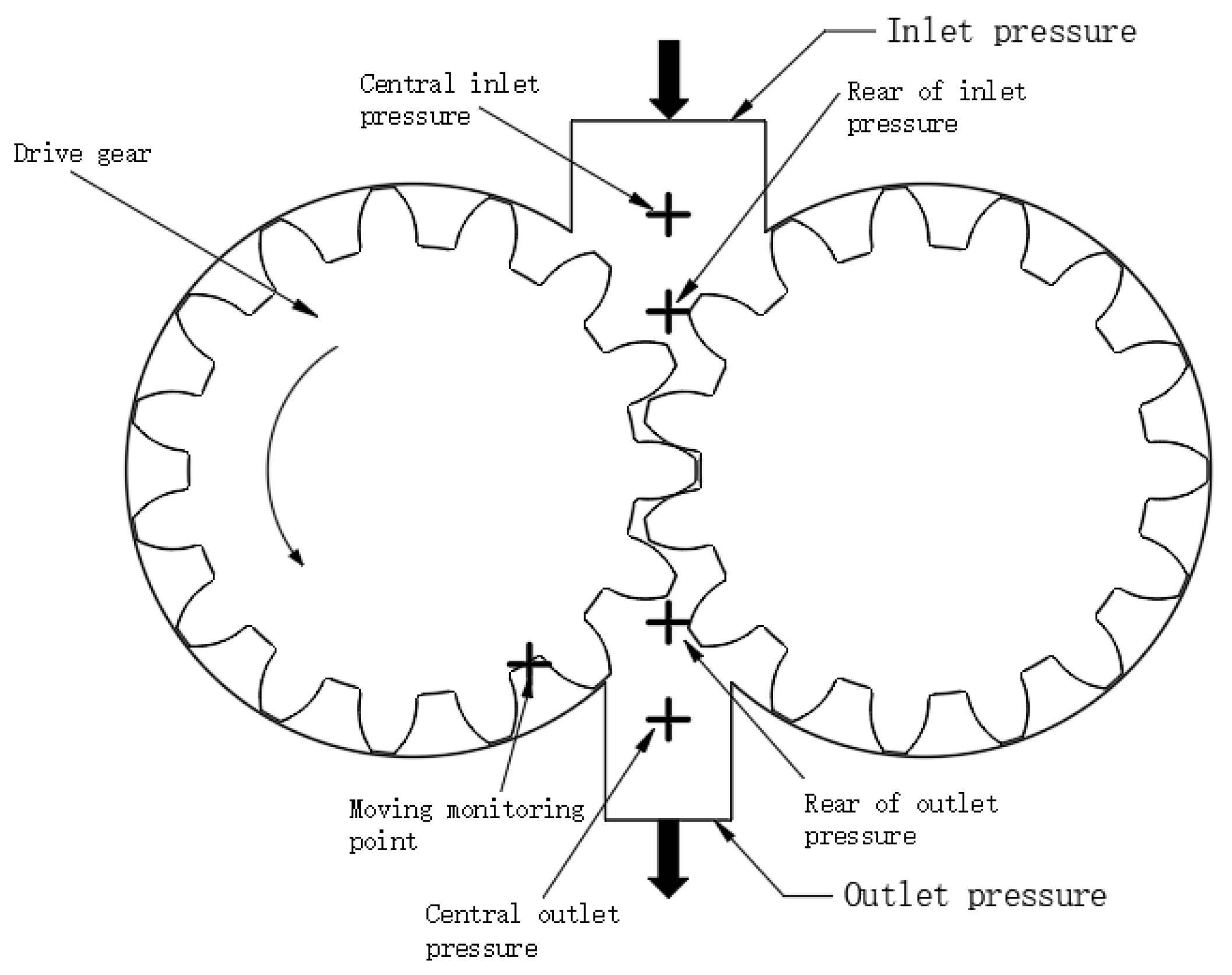
The geometric parameters of the different tooth profiles of the pure rolling cylindrical gears proposed in this paper were determined based on the basic design parameters and geometric dimension calculation formulas. Figure 4 shows a 2D model of a pair of pure rolling cylindrical gears with different tooth profiles, calculated using Table 1 and Table 2. This model was imported into Fluent for meshing, where the mesh type was triangular. The turbulence model was set as the realizable k–epsilon model, with an inlet pressure of standard atmospheric pressure and an outlet pressure of 2.5 MPa. The oil material was set to fuel oil liquid. The driving gear rotated counterclockwise at a speed of 1450 r/min. The dynamic mesh method utilizes spring smoothing and remeshing. Five monitoring points were set up, as shown in Figure 4: the central inlet pressure point, the rear inlet pressure point, a moving monitoring point, the central outlet pressure point, and the rear outlet pressure point. The moving monitoring point rotated along with the driving gear to primarily monitor pressure trend changes during gear rotation, while the other four points were fixed monitoring points, mainly used to observe pressure trend changes at specified points in the gear pump.
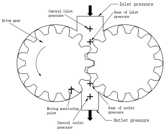
Figure 4.
2D model of parabolic profile of pure rolling cylindrical gear pump.
5. Results
Through fluid simulation analysis, the pressure fluctuation and fluid flow state of different tooth profiles of pure rolling helical gear pumps could be obtained. Since the pressure and velocity contour maps for different tooth profile designs of pure rolling helical gear pumps are similar, the following images show the parabolic tooth profile’s pressure and velocity contour maps as examples.
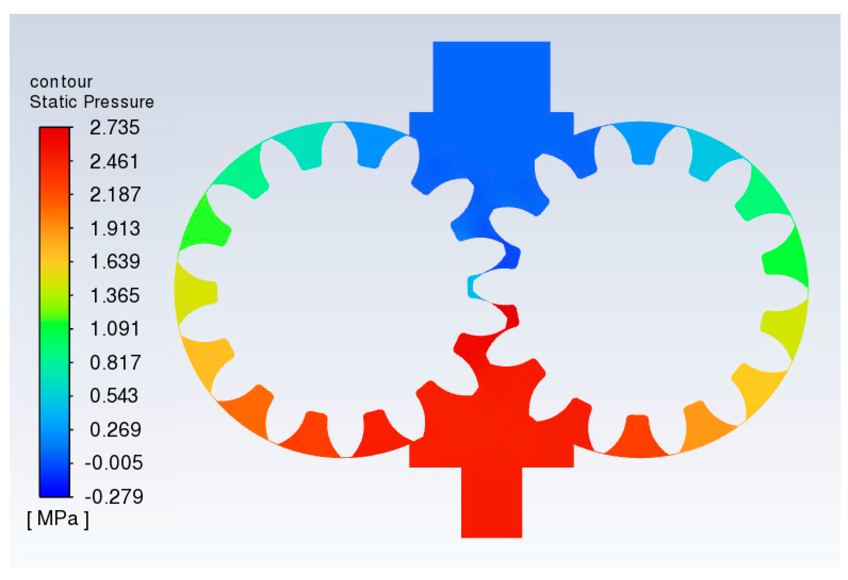
Figure 5 shows the pressure contour map of the parabolic tooth profile pure rolling helical gear pump at 0.02 s, while Figure 6 presents the velocity contour map at the same time. From the pressure contour map, it was observed that the pressure within the pump chamber gradually increased from the inlet to the outlet, and the maximum pressure in the pump was close to the outlet pressure, indicating that the pure rolling helical gear pump did not experience significant oil trapping during meshing.
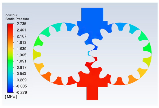
Figure 5.
Pressure diagram of a parabolic profile of the pure rolling cylindrical gear pump at 0.02 s.

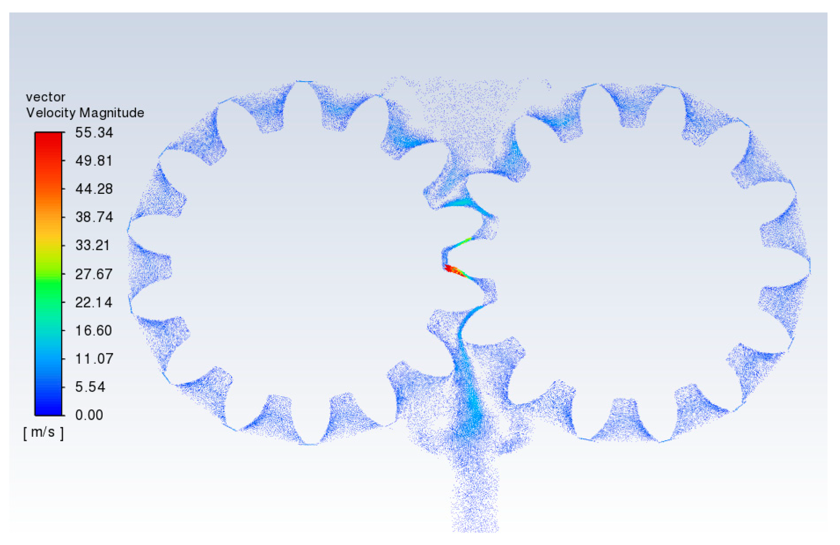
Figure 6.
Velocity diagram of a parabolic profile the pure rolling cylindrical gear pump at 0.02 s.
The velocity contour map revealed that due to the high-speed flow of fluid with the gear rotation, the flow near the inlet and outlet was slower, resulting in vortex formation as they met, leading to some outlet flow loss. Additionally, because of the pressure difference between the inlet and outlet of the external gear pump, oil was squeezed out through the gaps in the meshing area. The red arrows in Figure 6 indicate the speed and direction of the oil being extruded from the meshing area.
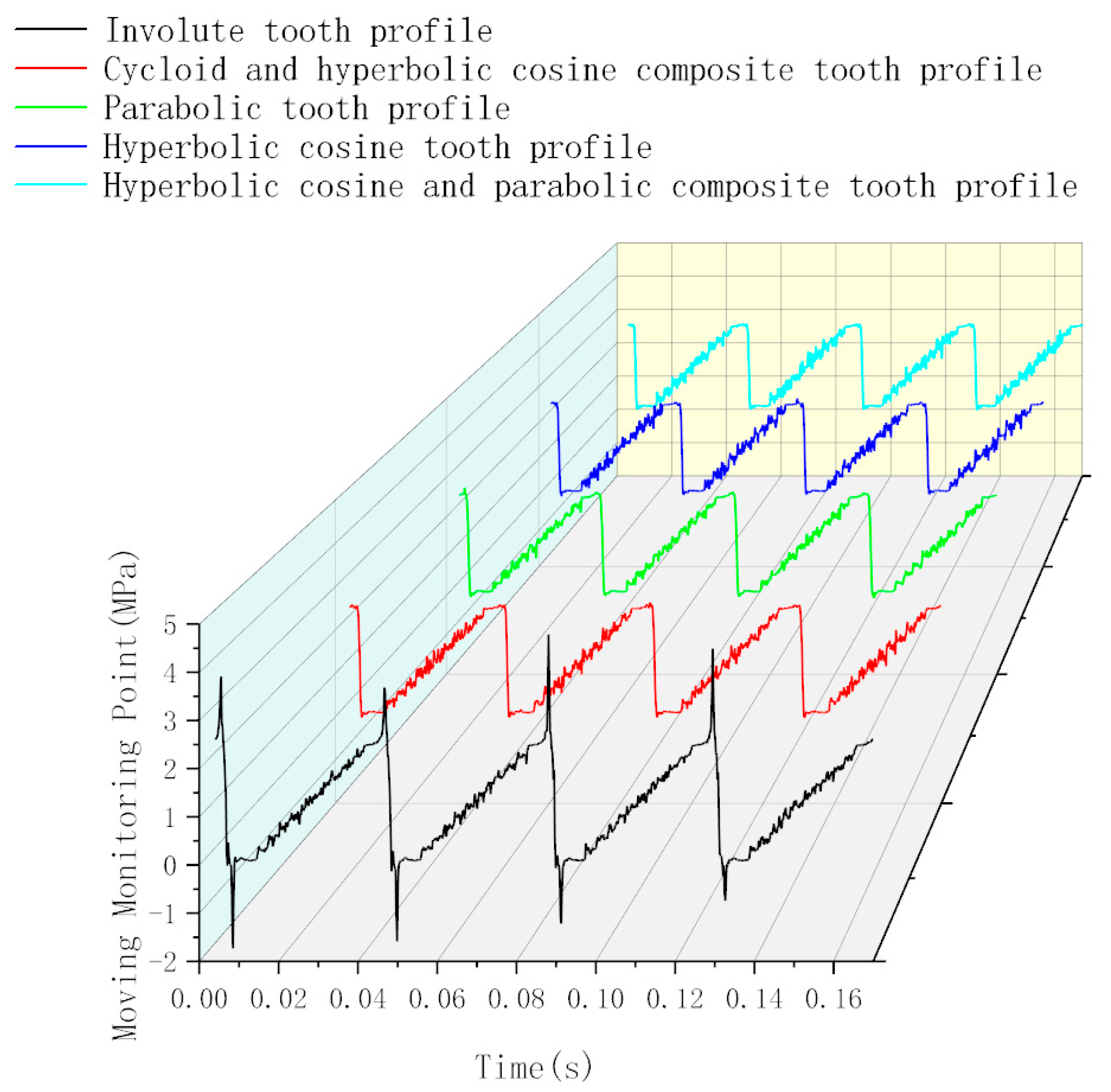
As shown in Figure 7, the pressure variation at the moving monitoring point for different tooth profile pure rolling gear pumps and the involute spur gear pump was observed. This point moved with the gear rotation, first passing through the meshing area, where it detected a sudden pressure increase followed by a sharp drop. The pressure then increased as the gear rotated, stabilizing at the set working pressure once the point reached the outlet pressure region. The reason for the sudden pressure spikes and drops in the meshing area of the involute spur gear is due to oil trapping in this region. As the meshing occurred in the involute spur gear pump, the closed volume of trapped oil gradually decreased, preventing the oil from flowing out. Consequently, this trapped oil area experienced pressures higher than the working pressure, with a peak of approximately 4.79 × 10⁶ Pa. On the other hand, as the involute spur gear rotated, the closed volume in the oil-trapping region expanded, causing a pressure drop due to the lack of oil intake, which led to vacuum formation. This resulted in a sharp pressure decrease, with the minimum pressure reaching approximately −1.73 × 10⁶ Pa.
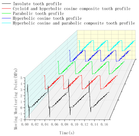
Figure 7.
Pressure comparison chart at mobile monitoring points: pure rolling external gear pump versus spur gear with various tooth profiles.
Since pure rolling helical gears exhibit point contact and only axial overlap, there is theoretically no oil trapping. The simulation results confirmed that different tooth profiles of the pure rolling helical gear pumps could significantly improve pressure pulsation in the meshing region. From Table 4, it can be observed that when the oil volume in the meshing region reached its minimum, the maximum pressure of the hyperbolic cosine and parabolic composite tooth profile reached approximately 2.60 × 10⁶ Pa. When the gears disengaged and the oil volume in the meshing area began to increase from the minimum, the minimum pressure for this composite profile reached approximately −2.55 × 10⁴ Pa. Compared to the involute spur gear, the effective positive pressure of the hyperbolic cosine and parabolic composite tooth profile was reduced by 45.67%. Various types of tooth profiles achieved a maximum pressure of around 2.70 × 10⁶ Pa, indicating that these profiles experienced the smallest maximum and minimum pressure pulsations in the meshing region relative to the involute profile.
Table 4.
Maximum and minimum pressure values at moving monitoring points in pure rolling helical gear pumps with different tooth profiles.
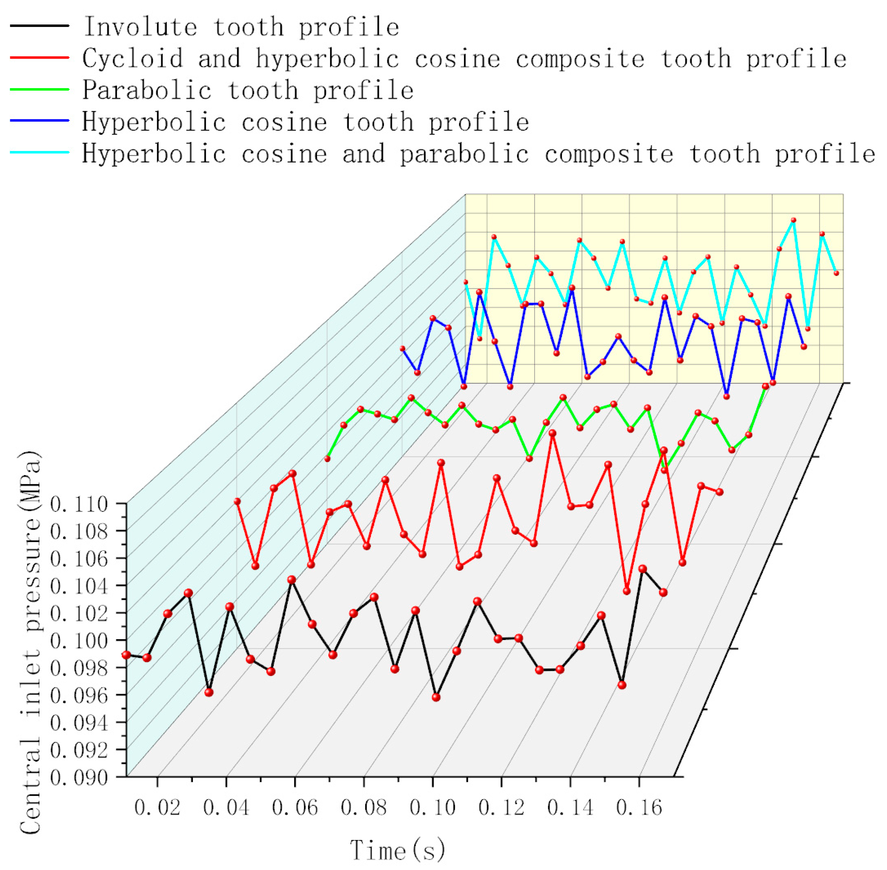
By calculating the standard deviation of the pressure fluctuations at the central monitoring point of the inlet, the degree of fluctuation around the average pressure value for different tooth profiles in pure rolling helical gear pumps could be described. A larger standard deviation indicates greater deviation from the average pressure, reflecting increased pressure curve fluctuations. As shown in Figure 8 and Table 5, at a rotational speed of 1450 r/min, the standard deviation of pressure pulsation for the involute external spur gear, cycloid and hyperbolic cosine composite profile, hyperbolic cosine profile, and hyperbolic cosine and parabolic composite profile in the pure rolling helical gear pumps was around 3.50 × 10³ Pa. This suggests a similar pressure pulsation trend for these gear pumps. The pressure pulsation range for the hyperbolic cosine profile, the hyperbolic cosine and parabolic composite profile, and the cycloid and hyperbolic cosine composite profile remained stable at approximately 1.01 × 10⁵ Pa. The average pressure values across the different profiles and the involute spur gear did not differ significantly; however, the parabolic profile had a smaller standard deviation than the other profiles, indicating that its pressure pulsation was relatively lower compared to the other profiles and the involute spur gear.
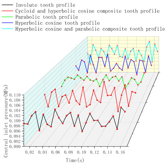
Figure 8.
Pressure comparison chart between pure rolling gear pumps with different tooth profiles and involute spur gears at the central pressure inlet.
Table 5.
Standard deviation of pressure at the central inlet section for helical gear pumps with pure rolling and spur gear pumps with involute tooth profiles.
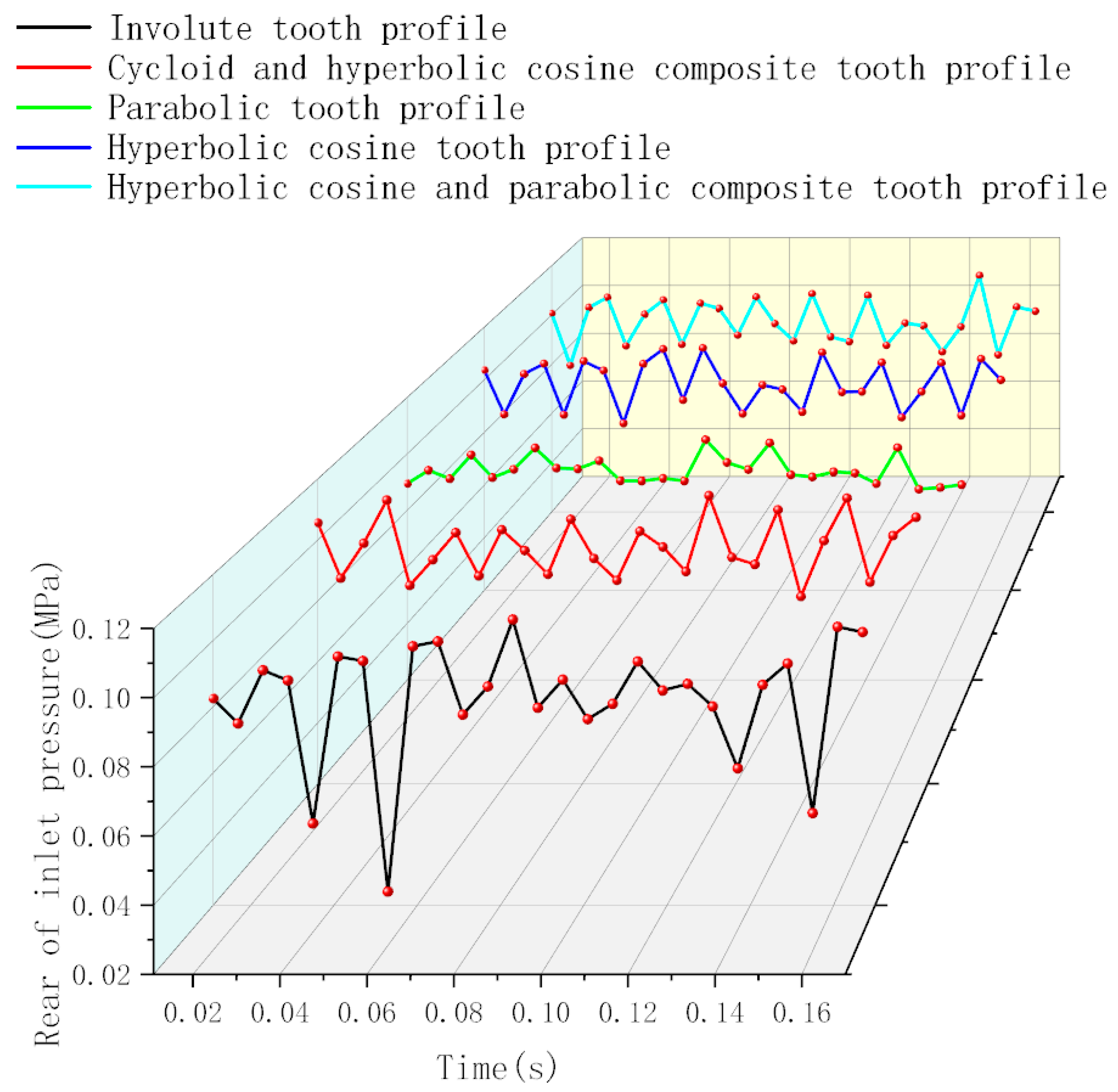
As shown in Figure 9, the fluctuation trends of the pressure curves at the central inlet monitoring point and the rear inlet monitoring point for different tooth profiles in the pure rolling external gear pumps were similar to those in Figure 8, both displaying wave-like patterns. From Table 6, it is evident that the pressure pulsation range at the rear inlet monitoring point was larger for different tooth profiles in the pure rolling external gear pumps. Comparing the central inlet and rear inlet monitoring points for various pure rolling helical gear pumps, the pressure fluctuation intensified. As illustrated in Figure 7, this is because when the gears disengaged, the oil volume in the meshing region increased, creating a local vacuum and resulting in microjets, which led to pressure fluctuations detected at the monitoring points.
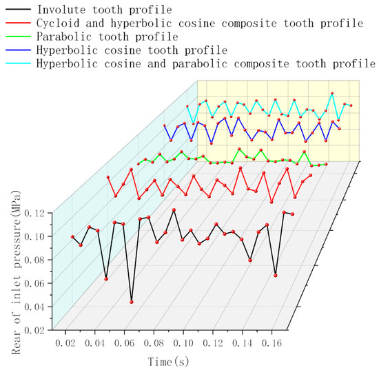
Figure 9.
Pressure comparison chart for pure rolling external gear pumps and spur gear pumps with different tooth profiles at the rear inlet.
Table 6.
Standard deviations of pressure at the rear of the pressure inlet in the helical gear pumps and spur gear pumps with different tooth profiles during pure rolling.
According to Table 6, the standard deviation of the pressure in the involute spur gear pump was smaller than that of the different pure rolling helical gear profiles, meaning that the pressure pulsation fluctuated relatively less around the average pressure value.
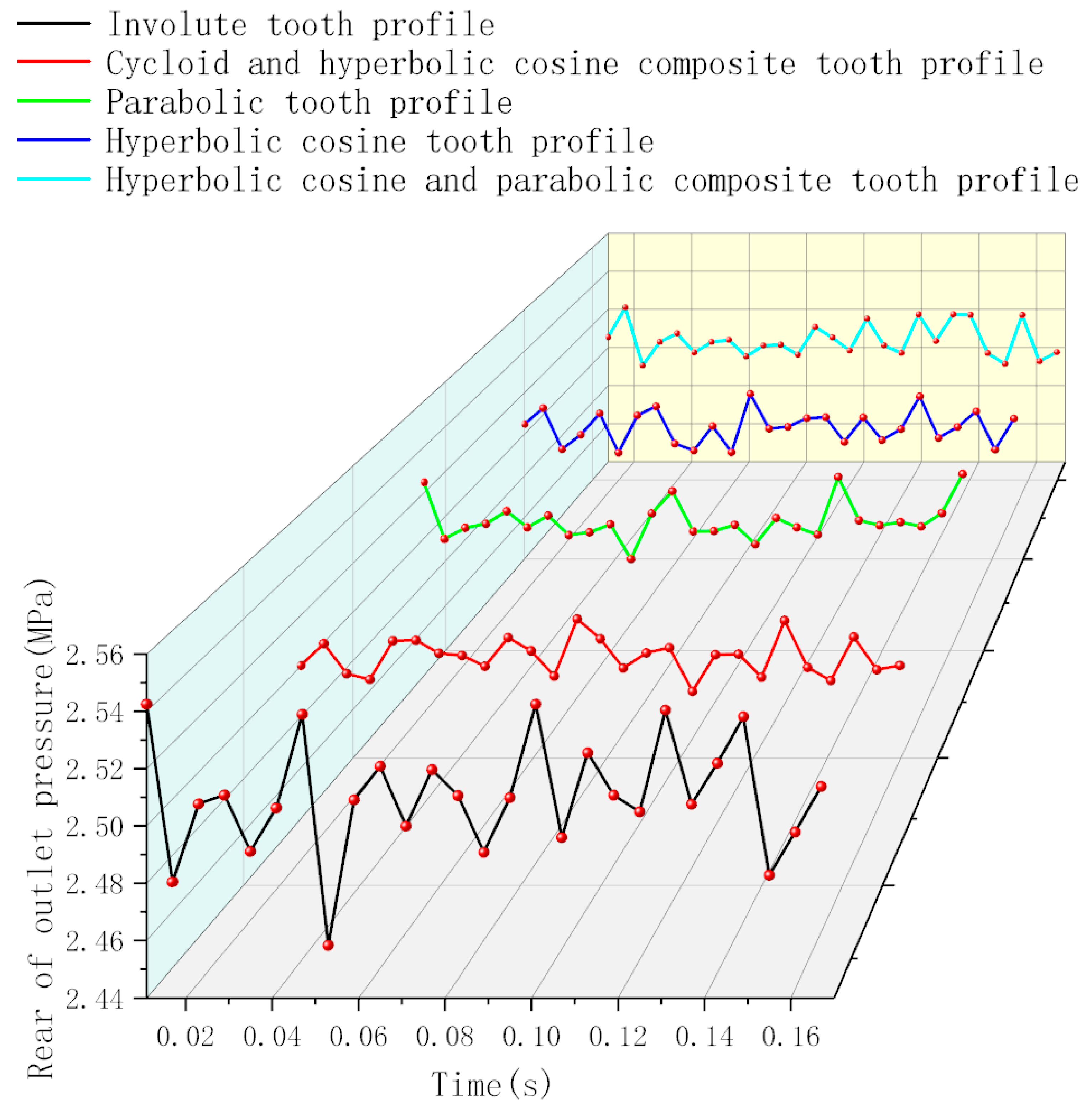
From Table 7 and Figure 10, the pressure fluctuation trends were generally similar across different pure rolling helical gear profiles, with the parabolic profile having the smallest standard deviation and an average pressure value close to the set working pressure. Compared to other profiles, such as the cycloid and hyperbolic cosine composite, the hyperbolic cosine profile, and the hyperbolic cosine and parabolic composite profiles, although the average values of these profiles were similar, their pressure pulsation was higher.
Table 7.
Standard deviation of pressure at the rear of the pressure outlet for pure rolling helical gear pumps and involute spur gear pumps with different tooth profiles.

Figure 10.
Pressure comparison chart for a pure rolling external gear pump with different tooth profiles with a spur gear located at the rear of pressure outlet.
Compared to the involute spur gear pump, the pure rolling helical gear pumps with different tooth profiles exhibited smaller standard deviations in pressure fluctuation and average pressure values closer to the set outlet pressure.
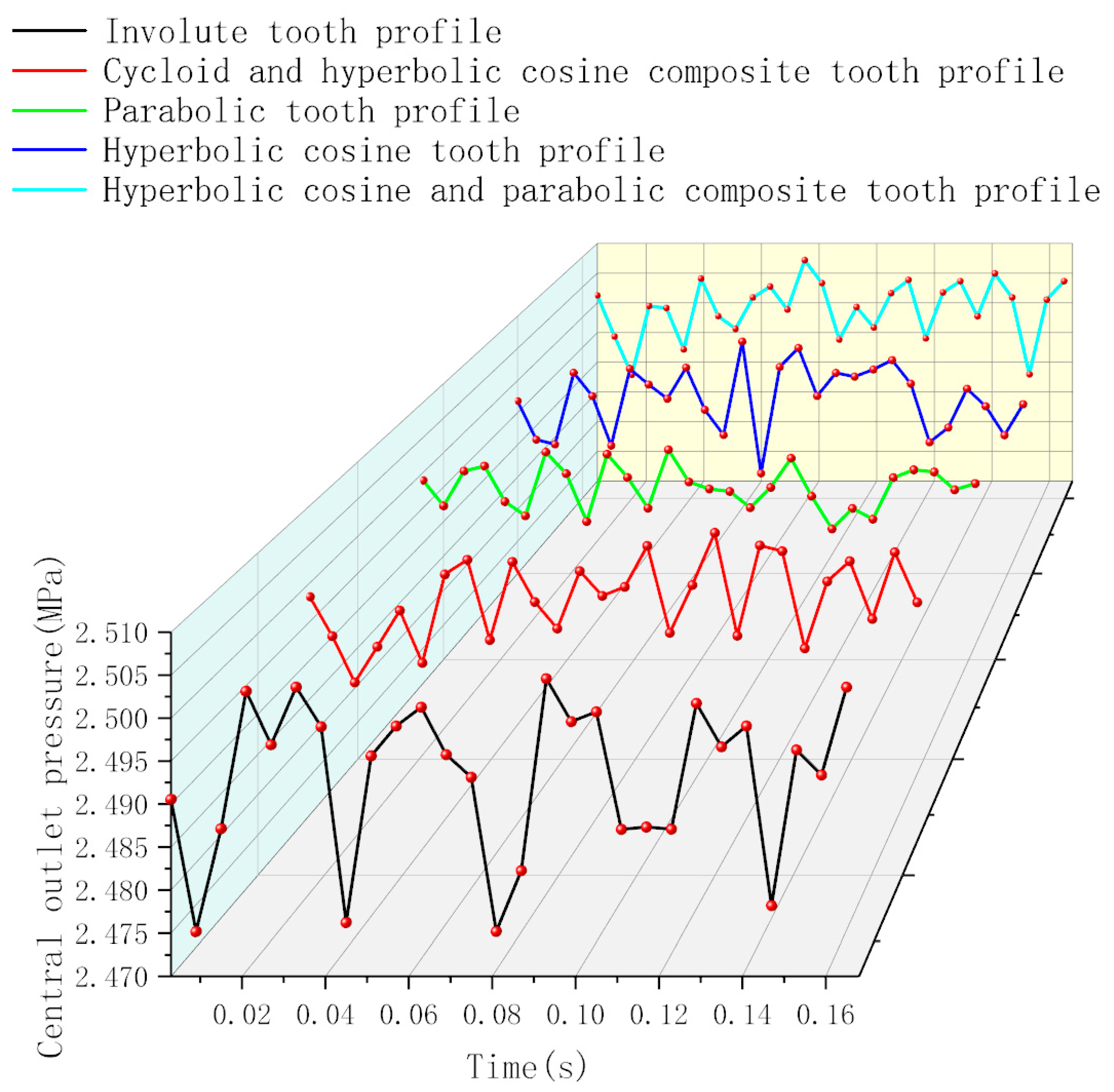
From Figure 11 and Table 8, it can be observed that the average pressure for different tooth profiles of the pure rolling helical gear pumps was approximately 2.50 × 10⁶ Pa. Based on the pressure standard deviation, the parabolic profile exhibited smaller outlet pressure pulsation in the central region compared to other tooth profile types. When comparing the pressure pulsation at this point between different pure rolling helical gear profiles and the traditional involute spur gear, the standard deviation of the involute spur gear was higher than that of the pure rolling helical gears with different profiles, indicating greater pressure pulsation for the involute spur gear.
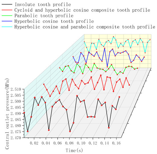
Figure 11.
Pressure comparison chart for a pure rolling external gear pump featuring varied tooth profiles with a spur gear at the central pressure outlet.
Table 8.
Standard deviation of pressure at the central of the pressure outlet for pure rolling helical gear pumps and involute spur gear pumps with different tooth profiles.
6. Conclusions
- (1)
- This paper presents a pure rolling helical gear pump based on the active design of meshing line functions and designs of tooth profiles using various curve functions, ultimately establishing mathematical models and a 2D flow field model for pure rolling helical gears with different profiles.
- (2)
- Using ANSYS 2022 R1, a comparative analysis was conducted on the pressure pulsation performance at fixed points, as well as the maximum and minimum pressure pulsation values in the meshing region, for the parabolic tooth profile of pure rolling helical gear and a CBB-40 involute spur gear pump. This study indicated that the pure rolling helical gear pump with a parabolic tooth profile exhibited 42.81% lower effective positive pressure in the meshing region compared to the involute spur gear pump, while the maximum effective negative pressure was approximately 27 times smaller. Moreover, the pressure pulsations in the middle and rear regions of the inlet and outlet pressure zones were reduced by 33.1%, 6.33%, 57.27%, and 69.61%, respectively, compared to the involute spur gear pump.
- (3)
- The pure rolling helical gear pump with a parabolic tooth profile exhibited 33.1%, 6.33%, 57.27%, and 69.61% lower pressure pulsations in the middle and rear regions of the inlet and outlet pressure zones, respectively, compared to the involute spur gear pump. Among different curve functions used as tooth profiles for pure rolling helical gear pumps, the parabolic profile exhibited the smallest pressure pulsation.
- (4)
- A three-dimensional flow field analysis of pure rolling cylindrical gear pumps with different profiles requires further in-depth research.
Author Contributions
Conceptualization, Z.C. and Y.L.; methodology, Z.C. and Y.L.; software, A.F.-A.; validation, X.X., C.H., and Y.C.; formal analysis, K.Z. and Y.C.; data curation, Z.C. and Y.L.; writing—original draft preparation, Y.L., Z.C., and C.H.; writing—review and editing, K.Z., Y.C., and X.X.; supervision, Y.C.; funding acquisition, Z.C. All authors have read and agreed to the published version of the manuscript.
Funding
This work was supported by the National Natural Science Foundation of China (Grant No. 52275073 and 52405056); Natural Science Foundation of Chongqing (Grant No. CSTB2022NSCQ-MSX1305); and Program for Scientific Research Start-Up Funds of Guangdong Ocean University (Grant No. YJR23002, YJR22016, YJR23010, and YJR24019).
Data Availability Statement
The raw data supporting the conclusions of this article will be made available by the authors on request.
Conflicts of Interest
The authors declare no conflicts of interest.
References
- Ding, W.; Zhang, S. Design points of BCB-B variable gear pump. Mach. Tool. Hydraul. 1998, 4, 71. [Google Scholar]
- Wu, C. Study on Internal Flow Field and Speed Limit of External Involute Spur-Gear Pump. Master’s Thesis, Lanzhou University of Technology, Lanzhou, China, 2019. [Google Scholar]
- Su, R. Study on Theoretical Analysis and Simulation test of the Trapping Problem in Gear Pump. Master’s Thesis, Hebei University of Engineering, Handan, China, 2012. [Google Scholar]
- Li, L.; Chen, K.; Zhan, C. Simulation analysis of flow characteristics of external gear pump considering cavitation. J. Wuhan Uni. Sci. Tech. 2021, 44, 262–269. [Google Scholar]
- Mithun, M.; Koukouvinis, P.; Karathanassis, I.; Gavaises, M. Numerical simulation of three-phase flow in an external gear pump using immersed boundary approach. Appl. Math. Mod. 2019, 72, 682–699. [Google Scholar] [CrossRef]
- Li, M. Study on Dynamic Evolution Process and Influence of Gas Phase in Gear Pump Cavitation. Ph.D. Thesis, Lanzhou University of Technology, Lanzhou, China, 2019. [Google Scholar]
- Bian, G. Research on Optimization Design of External Helical Gear Pump Based on Pumplinx. Master’s Thesis, Lanzhou University of Technology, Lanzhou, China, 2023. [Google Scholar]
- Li, M. Analysis and Research on the Trapped Oil Phenomenon of External Involute Gear Pump. Master’s Thesis, Lanzhou University of Technology, Lanzhou, China, 2016. [Google Scholar]
- Wang, W. The Study on Gear Pump’s Cavitation Characteristics under Wide Temperature Range and Variable Velocity Conditions. Master’s Thesis, Lanzhou University of Technology, Lanzhou, China, 2019. [Google Scholar]
- Qiang, Y.; Wang, W.; Luo, X.; Xiang, K.; Wei, L. Effect of Rotating Speed on Gear Pump Flow Field Cavitation Intensity. Hydraul. Pneum. Seals 2020, 2, 15–19. [Google Scholar]
- Li, Y. Study on Flow and Pressure Characteristics and Application of External Gear Pump. Master’s Thesis, Taiyuan University of Technology, Taiyuan, China, 2019. [Google Scholar]
- Wen, C.; Li, Y. Higher-speed Trapped-oil Pressure Research and Relief-groove Invention for Gear Pump. J. Mech. Transm. 2019, 43, 149–151. [Google Scholar]
- Li, Y.; Liu, K. Precise simulation analysis of relief area of external spur-gear pump. Trans. Chin. Soc. Agric. Eng. 2009, 25, 42–45. [Google Scholar]
- Liang, Y. Double Circular Arc Gear Pump Design. Master’s Thesis, China Academy of Machinery Science and Technology, Zhengzhou, China, 2015. [Google Scholar]
- Yu, J. Optimum Design and Performance Analysis of Circular-Arc Gear Pump with Parabola Transition Curve. Master’s Thesis, Harbin Institute of Technology, Harbin, China, 2017. [Google Scholar]
- Li, S. Dynamic Performance Simulation and Experimental Research of Circular Arc Helical Gear Pump. Master’s Thesis, Harbin Institute of Technology, Harbin, China, 2017. [Google Scholar]
- Yin, W. Research on Design Theory and Performance of Double Circular Arc Line Gear Pump. Master’s Thesis, South China University of Technology, Guangzhou, China, 2023. [Google Scholar]
- Zhou, Y.; Hao, S.; Hao, M. A two-dimensional numerical analysis of a circular-arc gear pump operating at high pressures and high speeds. J. Process. Mech. Eng. 2017, 231, 432–433. [Google Scholar] [CrossRef]
- Gao, W.; Gao, S.; Li, J.; Wu, W. Mechanism and Solution for Oil Trapped from Helical Gear Pump. Mech. Eng. Auto. 2010, 4, 168–170. [Google Scholar]
- Chen, Y. Line Gear; Science Press: Beijing, China, 2014. [Google Scholar]
- Zhang, D. Research on the Design Theory and Processing Technology of Line Gear with Plane Curve. Master’s Thesis, South China University of Technology, Guangzhou, China, 2020. [Google Scholar]
- He, C. Study on Design Theory of Tooth Profile for Parallel Axis Line Gear. Ph.D. Thesis, South China University of Technology, Guangzhou, China, 2022. [Google Scholar]
- Lv, Y. Study on Design Theory of Skew Line Gear. Ph.D. Thesis, South China University of Technology, Guangzhou, China, 2016. [Google Scholar]
- Yao, L. Study on Design Theory and CNC Manufacturing Method of the Concave Convex Arc Line Gear. Ph.D. Thesis, South China University of Technology, Guangzhou, China, 2018. [Google Scholar]
- Chen, Z.; Zeng, M.; Fuentes, A. Computerized design, simulation of meshing and stress analysis of pure rolling cylindrical helical gear drives with variable helix angle. Mech. Mach. Theory 2020, 153, 1–19. [Google Scholar] [CrossRef]
- Chen, Z.; Zeng, M.; Fuentes, A. Geometric design, meshing simulation, and stress analysis of pure rolling cylindrical helical gear drives. J. Mech. Eng. Sci. 2020, 234, 3102–3115. [Google Scholar] [CrossRef]
- Chen, Z.; Zeng, M.; Fuentes, A. Geometric Design, Meshing Simulation, and Stress Analysis of Pure Rolling Rack and Pinion Mechanisms. J. Mech. Des. 2020, 142, 1–10. [Google Scholar] [CrossRef]
- Chen, Z.; Chen, Y.; Xiao, X.; Liu, H.; Fuentes, A. Computerized design, simulation of meshing, and stress analysis of curvilinear cylindrical gears based on the active design of the meshing line function. Mech. Mach. Theory 2023, 188, 1–28. [Google Scholar] [CrossRef]
- Fuentes-Aznar, A.; Iglesias-Victoria, P.; Eisele, S.; Gonzalez-Perez, I. Fillet geometry modeling for nongenerated gear tooth surfaces. In Proceedings of the International Conference on Power Transmissions, Chongqing, China, 27–30 October 2016; pp. 431–436. [Google Scholar]
Disclaimer/Publisher’s Note: The statements, opinions and data contained in all publications are solely those of the individual author(s) and contributor(s) and not of MDPI and/or the editor(s). MDPI and/or the editor(s) disclaim responsibility for any injury to people or property resulting from any ideas, methods, instructions or products referred to in the content. |
© 2025 by the authors. Licensee MDPI, Basel, Switzerland. This article is an open access article distributed under the terms and conditions of the Creative Commons Attribution (CC BY) license (https://creativecommons.org/licenses/by/4.0/).