Abstract
Stringent global regulations increasingly demand significant reductions in emissions from industrial gas turbines, underscoring the need for optimized combustor liner cooling to achieve lower emissions and enhanced thermal efficiency. Uniform liner temperature is crucial, as it minimizes thermal stresses, reduces fuel consumption, and improves component reliability. Although impinging jet arrays with flow passages are widely utilized for cooling, cross-flow effects can diminish heat removal efficiency from the target surface. In contrast, the induction of swirl has the potential to improve heat transfer and its distribution uniformity. This study investigates the impact of varying swirl intensities, induced by incorporating a cross-twisted tape into the nozzle, on the flow and heat transfer characteristics of the jet array. Six twisted angles (0°, 15°, 30°, 45°, 60°, and 75°) were evaluated, where the introduction of the twisted tape divided the jet into four streams, leading to complex interactions that alter the cooling performance at the target surface. The results show that moderate swirl angles (15° and 30°) enhance temperature uniformity and provide more consistent heat transfer across the surface compared to higher swirl or no swirl. However, excessive swirl (60° and 75°) can hinder jet penetration and reduce cooling effectiveness in downstream regions. Overall, the introduction of swirl improves temperature uniformity but also increases pressure drop due to heightened turbulence.
1. Introduction
Gas turbine engines are extensively employed in aviation, power generation, and marine propulsion systems [1,2,3,4]. With the global drive toward net zero emissions and increasingly stringent regulations—such as the International Energy Agency’s Energy Technology Perspectives [5] and the EU Industrial Emissions Directive [6]—advancements that improve turbine efficiency while reducing pollutant emissions have become critically important. One strategy to achieve this is by elevating combustion temperatures, which can improve efficiency; however, higher combustion temperatures will result in exceptionally high wall temperatures in gas turbine combustors. Since these elevated wall temperatures can exceed the finite allowable limits of the metal materials used, it becomes vital to enhance overall cooling performance and implement targeted protection in regions susceptible to thermal overload [7]. One of these important components is the combustor liner. Over recent decades, extensive research has focused on improving the efficiency of cooling systems of combustor liner in gas turbines [8,9,10,11].
A combustor liner forms the barrier between the high-temperature combustion gases and the gas turbine combustor’s structural frame, helping to contain and shape the combustion process while withstanding intense thermal and mechanical stresses [12]. During combustion, temperatures can soar to levels that well exceed the material limits of the engine components. To mitigate this, the liner is typically equipped with advanced cooling strategies such as film cooling, impingement cooling, or even more sophisticated approaches like swirling impinging jet arrays [1]. However, conventional film cooling methods often rely on compressor bleed air, which can alter the ideal air-to-fuel ratio and, in turn, compromise optimal combustor performance [11]. Optimal design of the combustor liner is essential because uniform heat distribution minimizes thermal gradients and hot-spots, while effective cooling keeps the combustor within its designed temperature limits to lower NOx emissions, and enhanced thermal management extends component life and improves reliability in high-stakes applications such as aviation, power generation, and marine propulsion [7,8,11].
Impingement cooling is a widely used technique to improve cooling film coverage, and previous studies have demonstrated that increasing the amount of cooling air leads to enhanced performance, the two configuration for gas turbine combustor cooling (reverse flow and forward flow) are shown in Figure 1 [13]. For impingement cooling applications, the target surface is cooled by an array of nozzles (small holes) which provides a high-velocity cooling stream. The overall performance of impinging jets is highly dependent on several flow factors, including operating conditions such as Reynolds number, , where is fluid density, is the jet exit velocity, D is the nozzle diameter, and is fluid dynamic viscosity, and swirl number, geometric parameters (such as nozzle diameter and nozzle-to-surface distance), and cross-flow effects (like jet-to-jet spacing and the inline or staggered arrangement of the nozzles) [13]. This parameter provides insight into how much swirl is present in the jet [14].
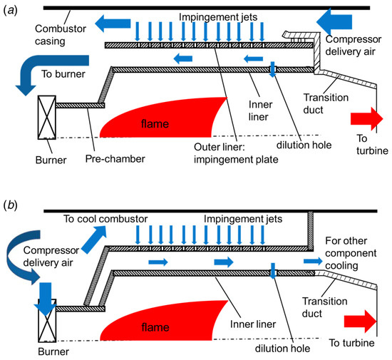
Figure 1.
The cooling concept of gas turbine combustor (a) reverse flow and (b) forward flow [13].
Recently, research has been focused on optimization of the hole structure to enhance the effectiveness of impingement cooling [15,16]. At small nozzle-to-surface impingement distances—that is, the perpendicular distance from the nozzle exit to the target surface—impinging jets demonstrate impressive heat transfer capabilities. This feature makes them an attractive option for cooling applications such as turbine blades and industrial gas turbine combustor liners [10]. Lutum et al. [17] examined the impact of the length-to-diameter ratio of cooling holes on film cooling performance and found that a higher ratio enhances performance, likely due to the complete development of the cooling airflow within the holes. In a related study, Andreini et al. [18] conducted a multi-parametric analysis of the blowing ratio, porosity, and length-to-diameter ratio, ultimately developing an empirical formula to quantify the area-average cooling effectiveness.
Due to the inherent non-uniformity of flow and temperature in the combustor, the wall temperature tends to be uneven, with localized high spots that surpass acceptable limits and can cause cracking and buckling in the combustor liners. Thus, it is crucial to adopt designs that help a more uniform temperature distribution, as doing so minimizes thermal gradients and hot-spots, preserves structural integrity, and improves overall system efficiency. Several studies have explored how impinging jets can deliver a more uniform temperature distribution [19,20]. Their performance is generally evaluated based on the total heat removed from the surface and the uniformity of the heat distribution [13]. Moreover, introducing swirl into the flow can potentially improve the uniformity of heat transfer. Swirl can be generated either aerodynamically—using tangential ports to inject flow in a manner that reduces central flow dead zones, albeit at the cost of increased system complexity—or geometrically [21].
Numerous experimental and numerical studies have examined how factors such as the angle of the holes, the arrangement of holes (inline or staggered) on the orifice plate, and the spacing between holes—both in the streamwise direction () and the spanwise direction ()—influence impingement heat transfer [13]. These dimensions are illustrated in Figure 2. The nozzle-to-surface distance, known as the impingement distance (), is also important [22,23]. As the impingement distance increases, the momentum of the jet decreases, which can negatively impact the effectiveness of heat transfer [24]. Additionally, increasing generally enhances heat transfer, but it also requires a greater amount of bleed air, which can disrupt the optimal air-to-fuel ratio in the combustor. In gas turbine combustor liner cooling, typical values of are on the order of [21]. For impinging jet arrays, the streamwise and spanwise distance plays an important role in the heat transfer characteristics resulting in strong jet-jet interaction. Typically, for the same , smaller distances between jets ( and ) can lead to higher heat transfer rates but to keep the constant, more bleeding air will be required [25]. Huber et al. [26] found that the highest average and most uniform Nusselt number, , where h is the convective heat transfer coefficient and is the thermal conductivity of the fluid, distribution is observed when the jets’ stagnation region covers a large portion of the target surface. Goodro et al. [27] studied the effect of jet-to-jet spacing ranging from 8–12, also known as a sparse jet array; they observed the best performance at , which is also selected for the current study as well.
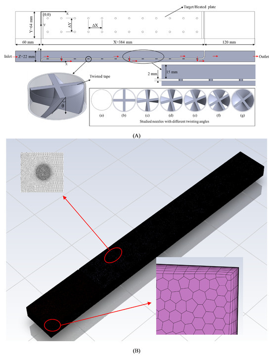
Figure 2.
(A) Schematic diagram of the computational domain with geometric nomenclature along with all tested nozzle (where (a) Base Case nozzle shape, (b) 0°, (c) 15°, (d) 30°, (e) 45°, (f) 60°, and (g) 75°) and (B) Unstructured polyhedral mesh.
The temperature ratio (TR), defined as the ratio of wall temperature to jet temperature, is an important parameter because higher values can significantly alter the thermophysical properties of the cooling fluid. Despite its relevance, there are relatively few studies on heat transfer characteristics at different temperature ratios, and most available literature focuses on low temperature ratios [26,28]. For example, Goodro et al. [27] investigated impinging jet arrays across six temperature ratios ranging from 1.06 to 1.73, and found that both local and average heat transfer decreased as the temperature ratio increased. Da Soghe et al. [29] examined the effect of temperature ratios from 1.125 to 2.05, though they did not provide explicit wall temperature data. Similarly, Liu [30] studied single- and triple-stage gas turbine liner coolers at two wall temperatures (750 K, and 1123 K, ) and observed a reduction in Nusselt number with increasing temperature ratio. The results showed that using triple-stage impingement could cut cooling air usage by almost 50%. with only a 16–18% reduction in heat removed compared to traditional single-stage designs—yielding a 61–66% improvement in cooling air effectiveness.
Our research employs an advanced computational fluid dynamics (CFD) approach to investigate a swirling impinging jet array for cooling industrial gas turbine combustor liners. The novelty of our work lies in the integration of geometrically induced swirl—achieved through twisted tape inserts in the nozzle design at various twist angles—with a strategically applied crossflow from compressor bleed air. This configuration is specifically engineered to maximize both the magnitude and uniformity of convective heat transfer, thereby mitigating elevated wall temperatures and improving overall thermal management. Critically, while a few studies [31,32,33] have explored the heat transfer characteristics of swirling impinging jet arrays, none have included the effect of cross-flow, nor have they focused specifically on gas turbine combustor liner applications. In contrast, our study examines the effect of swirling flow through the nozzle for impinging jet arrays with crossflow, targeting the cooling of gas turbine liners. One temperature ratio is tested along with heat transfer characteristics for nozzles both with and without twisted inserts. Five twisted angles (15°, 30°, 45°, 60°, and 75°), corresponding to different swirl intensities, are investigated for their impact on cooling performance. By simultaneously addressing critical parameters such as Reynolds number, swirl number, nozzle-to-surface distance, and temperature ratio, our method provides a robust and targeted solution for high-temperature industrial applications. Moreover, CFD offers distinct advantages over traditional experimental methods, including reduced development costs, detailed visualization of complex internal flow structures, and the flexibility to conduct extensive parametric studies under controlled conditions.
2. Methodology
Numerical Model
For turbulent flows in gas turbine combustors, resolving all scales of turbulence using direct numerical simulation (DNS) is not practical for real-world, high-Reynolds-number engineering applications due to the immense computational resources required. This limitation becomes especially significant in actual engineering practice, where numerous simulations are needed for design and optimization, making DNS computationally unfeasible. Instead, turbulence can be treated statistically using Reynolds-averaging, resulting in the Reynolds-averaged Navier–Stokes (RANS) equations [34]. This approach introduces additional terms representing turbulence, which must be modeled to achieve closure [35].
The conservation of mass and linear momentum equations for three-dimensional, incompressible, and steady-state flows are:
here, is the spatial coordinate in the i-th direction, is the mean velocity component in the i-th direction, is the fluid density, p is the mean pressure, is the Kronecker delta, are the components of fluctuating velocity and the overbar denotes a Reynolds average. Finally, are the Reynolds stress terms arising from turbulence.
To close the RANS equations, the Boussinesq hypothesis is commonly employed, relating the Reynolds stresses to the mean velocity gradients:
where is the turbulent (or eddy) viscosity, and k is the turbulent kinetic energy.
This study uses the Shear Stress Transport (SST) k– model [36] to provide closure for the RANS equations. The SST k– is widely being used for the impinging jet studies, the impingement region of impinging jets is quite complex and consists of a stagnation zone, transition region, and wall jet region. The SST model effectively blends the original k– turbulence model, which is robust and accurate near solid surfaces, with a transformed k– model that avoids sensitivity to free-stream conditions. This combination, achieved via blending functions, yields reliable predictions for complex flows such as impinging jets.
In the SST k– turbulence model, two transport variables are solved to characterize the state of turbulence throughout the flow. The first variable, turbulent kinetic energy k, quantifies the mean kinetic energy per unit mass contained in velocity fluctuations and serves as a measure of local turbulence intensity; mathematically, . The second variable, the specific dissipation rate , describes the rate at which the turbulent kinetic energy is dissipated by viscous action per unit of k, effectively setting the time scale and characteristic size of the turbulent eddies. In practical terms, larger values of correspond to faster dissipation and smaller-scale turbulence. Together, k and control the production, transport, and destruction of turbulence in the model, allowing for efficient prediction of turbulent effects without direct resolution of all flow scales.
The general form of transport equations for the turbulent kinetic energy k and the specific dissipation rate take the following form:
In these equations, the coefficients and are effective diffusivities for k and , respectively, and are given by
where and are turbulent Prandtl numbers for k and . Additionally, denotes the production of turbulent kinetic energy from mean velocity gradients. The term corresponds to the generation of . The quantities and describe the dissipation of k and due to turbulence, respectively. Source terms defined by the user are represented by and . The term signifies the cross-diffusion contribution. For further details on the model details, we refer the readers to ANSYS theory guide [37].
Turbulent heat transfer is modeled using the analogy between Reynolds-averaged turbulent transport of momentum and energy for steady-state flow. The resulting energy equation is
where E is the total energy per unit mass, T is temperature, is the specific heat at constant pressure, and is the turbulent Prandtl number. The effective deviatoric stress tensor is defined as
where is the sum of molecular and turbulent viscosity.
The combination of the RANS framework, SST k– turbulence closure, and Reynolds analogy for energy transfer, provides a comprehensive and computationally tractable method for simulating turbulent fluid flow and heat transfer in gas turbine combustor liners and similar high-performance configurations.
3. Simulation Setup
3.1. Numerical Schemes
The numerical simulations were performed using ANSYS Fluent 2020R2, which utilizes a finite-volume approach to discretize and solve the governing equations. Pressure–velocity coupling was achieved using the coupled scheme, while gradient reconstruction was carried out using the least-squares cell-based method. Spatial discretization of scalar transport equations and turbulence quantities was performed using a second-order upwind scheme to ensure both accuracy and stability.
For turbulence closure, the SST k– model was adopted, incorporating the production Kato-Launder modification and a production limiter for improved robustness in high-shear regions. To accurately capture the complex flow phenomena, especially in the stagnation and wall jet regions, the gamma-transport equation was employed. The inclusion of the gamma-transport equation facilitated enhanced prediction of transitional behavior between the stagnation and wall jet zones and contributed to more reliable convergence of the iterative solution, with normalized residuals maintained within acceptable thresholds.
3.2. Geometry Details
Figure 2 presents the computational domain, illustrating the geometry and associated nomenclature employed in this CFD investigation. In total, seven nozzle configurations are analyzed, including a benchmark case featuring a circular nozzle without any internal insert. To ensure a consistent basis for comparison of heat transfer performance, the nozzle exit area is held constant across all cases by adjusting the nozzle diameters accordingly.
The overall dimensions of the computational domain mirror those used in the previous validation study [9]. The target (impingement) surface measures 384 mm in length and 64 mm in width. In the streamwise direction, twelve rows of impingement holes are implemented, with each row containing two holes. The center-to-center spacing of the impingement holes is uniform in both the streamwise and spanwise directions, with . The nozzle-to-surface distance remains fixed at 5 mm for all simulations, corresponding to a non-dimensional spacing of .
3.3. Case Study Boundary Conditions and Non-Dimensional Parameters
The present study considers a representative gas turbine system with a power output of 13 MW and a compressor pressure ratio of 16. Air is used as the working fluid, with a compressor exit temperature estimated at 700 K based on standard gas turbine cycle correlations:
where K is the ambient inlet temperature, is the polytropic efficiency, is the specific heat ratio, and is the compressor pressure ratio [38,39]. The air discharged from the compressor is employed for cooling the combustor liner, resulting in an inlet pressure of 16 bar and an initial jet temperature K.
An overall pressure drop of 4% is assumed from the domain inlet to outlet. This assumption allowed to align with the baseline conditions used in the reference study by Liu [30]. This approach enables a comparison with established results while providing a consistent and validated benchmark for the analysis. Under these operating conditions, the jet Reynolds number () varies in the range to . To enable a systematic analysis of heat transfer and flow characteristics for the temperature ratios (), a constant uniform wall temperature () is imposed at the target (impingement) surface, thereby isolating the impact of temperature ratio effects from wall temperature non-uniformity. Periodic boundary conditions are imposed along the spanwise edges of the computational domain. The domain is populated with two rows of impinging jets, which allows for scrutiny of the fluid flow and thermal interactions between successive jet rows.
Physical properties of air are calculated at the film temperature,
and density is determined using the ideal gas law for moderately incompressible flow:
where is the operating pressure, R is the universal gas constant, and is the molecular weight of air. Fluid viscosity () is evaluated according to Sutherland’s law:
where kg/m·s, K, and K denote reference values for viscosity, temperature, and Sutherland’s constant, respectively.
The specific heat () and the thermal conductivity () are obtained from kinetic theory:
where denotes the degrees of freedom for the energy modes in air.
ANSYS Fluent applies these correlations internally to estimate thermal and transport properties of the working fluid during simulation. The primary reduced data includes the jet Reynolds number, the heat transfer coefficient (h), and the Nusselt number. The heat transfer coefficient at the surface is defined as follows:
where q is the local heat flux at the target surface and is the nozzle diameter for the case of the nozzle (a) shown in Figure 2, for other nozzle shapes is calculated by keeping the nozzle exit area constant.
4. Results
4.1. Validation and Mesh Sensitivity Analysis
A comprehensive mesh independence study was conducted to ensure the accuracy and reliability of the computational results. For this investigation, a three-dimensional unstructured polyhedral mesh was generated using ANSYS Fluent meshing tools. Polyhedral meshes are chosen due to their ability to accurately capture complex flow features when appropriately refined. Multiple prism layers were applied adjacent to the walls, ensuring that viscous effects were adequately resolved; the mesh was refined at the target surface to keep (for SST k– the recommended value is less than 5), supporting the fidelity of boundary layer predictions.
Prior to detailed analysis, a grid convergence (mesh sensitivity) assessment was performed. Several mesh sizes were evaluated to examine how further refinement influenced key outcome variables. The uncertainty introduced by discretization was quantified using the Grid Convergence Index (GCI), following Richardson’s extrapolation method, which predicts values corresponding to an infinitely fine mesh. The methodology for estimating and controlling numerical uncertainty was adopted from previous works in literature [40,41]. For each mesh, the characteristic cell size () was calculated as follows:
where is the domain area and is the number of cells in the ith grid. The refinement ratio () is defined as the ratio between the cell sizes of successive meshes. In this study, the minimum refinement ratio was 1.49, which meets the recommended threshold of 1.3 for credible GCI analysis [40,42]. The area-weighted average wall shear at the target surface was used as the primary parameter for the GCI calculations. Table 1 summarizes the results for each grid and its corresponding GCI value, and these findings are also visually represented in Figure 3. The grid convergence presented in Figure 3 is carried out for the wall shear of the target surface, wall shear is a sensitive indicator of near-wall resolution, reflecting the accuracy of both momentum and heat transfer predictions in wall-bounded turbulent flows. Since convective heat transfer at the wall is strongly governed by local shear, achieving grid independence for wall shear stress provides confidence that key thermal and hydrodynamic features are well-resolved. Moreover, computed Nusselt numbers in Figure 4 show close agreement with values reported in the literature, supporting the adequacy of the chosen mesh density. Based on the convergence analysis, a mesh with approximately 13 million cells was selected for all subsequent cases.

Table 1.
Grid Convergence Index (GCI) study.
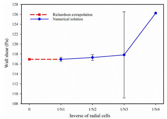
Figure 3.
Grid convergence study utilized to obtain optimal mesh size (non-swirling test case).
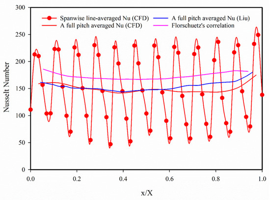
Figure 4.
Nusselt number validation with Liu et al.’s [30] and Florschuetz et al.’s [43] correlation for non-swirling circular nozzle (without insert) test case.
To further validate the mesh and simulation setup, the spanwise line-averaged Nusselt number in the streamwise direction was compared against the benchmark correlation developed by Florschuetz et al. [43], given as follows:
A comparison, shown in Figure 4, presents the pitch-averaged Nusselt numbers along the streamwise direction for the reference case. Results were also cross-validated with computational data reported in the literature [30]. The simulation predictions generally agree with the benchmarks, with the maximum deviation in wall Nusselt number being less than 15%, confirming the adequacy and reliability of the chosen mesh resolution and numerical approach.
4.2. Analysis
Six different nozzle inserts along with a base case (simple nozzle) are being investigated in this study. The twisting angel of the nozzle inserts is being varied from 0° to 75°, to introduce the different swirl intensities and evaluate corresponding thermal hydraulic performance.
Figure 5 shows the velocity contours in the streamwise (X) direction for several cases: the base case and insert twist angles () of 0°, 15°, 30°, 45°, 60°, and 75°. The numbers 1 to 12 mark the rows of holes arranged in the spanwise direction; these numbers help us discuss the behavior of jets from each row. In the base case, the first three jets hit the target surface almost at a right angle, generating wall jets that travel both upstream and downstream. For later jets, the upstream wall jet region becomes smaller. The interaction region, where wall jets from jets 1 and 2 meet (velocity near zero), is roughly centered between them; as we move downstream, this zone shifts closer to the downstream jet because of the increased momentum in the cross-flow from upstream jets. For the last three jets (rows 10–12), the strong cross-flow deflects the jets further downstream, but they still reach the target surface. When a twisting insert is used, a single jet splits into four separate jets, creating a low-velocity “dead zone” that is clearly visible at . For other twist angles, the dead zone is less prominent or only partly visible due to increased flow in the y direction caused by the swirl. As swirl intensity () increases, the impingement angle of jets from rows 9-12 grows steeper, and with greater swirl, some jets fail to reach the target surface. At and , jets from the last four rows do not reach the target surface at all. Additionally, in rows 1–3, the interaction region between wall jets shifts further downstream as the swirl increases.
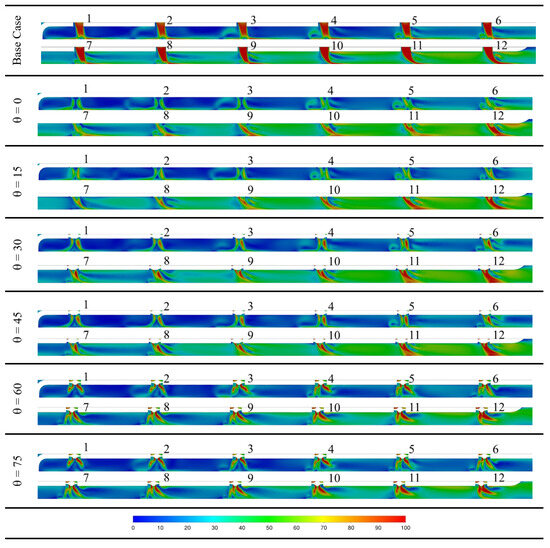
Figure 5.
Streamwise (X-direction) velocity contour plot for the base case and 0°, 15°, 30°, 45°, 60°, and 75°, same colour bar for all cases, . Numbers 1–12 in the figure represent the hole rows the lateral direction.
Figure 6 presents velocity contours in the spanwise (Y) direction for the base case and for twisted inserts with , , and . For row 1 in the base case, the jet flow is clearly defined and non-swirling. All characteristic regions of the impinging jet are present: the jet core, the stagnation (impingement) zone, and the wall jet region. The wall jet interactions between adjacent jets are nearly symmetrical in this configuration. However, when swirl is introduced with the twisted inserts, these interactions become progressively more asymmetrical as the swirl intensity increases.
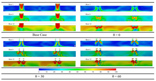
Figure 6.
Spanwise (Y) velocity contours for the base case and twisted inserts (, , ) at rows 1, 6, and 12, illustrating jet structure and crossflow effects. The contour in the image shows the magnitude of the velocity vector, .
At row 6 for the base case and for , the wall jet regions are still somewhat distinguishable, but the circulation caused by the wall jets has greater momentum than in row 1, resulting from increased crossflow. As the swirl intensity increases further, these wall jet regions start to disappear, replaced by stronger mixing between the jet and crossflow.
At row 12, the main jet regions remain identifiable, but the entire flow field is now dominated by crossflow. This shift means that, especially further downstream on the target surface, heat transfer is largely governed by the effects of the crossflow.
Figure 7 shows the jet velocities averaged over each nozzle area (), normalized by the overall average nozzle velocity (), for all twelve nozzles. In Figure 7a, the initial nozzles deliver less fluid compared to the later ones, as flow resistance through the nozzles decreases along the streamwise direction. Across all tested cases, the average jet velocity at nozzle 7 is nearly the same.
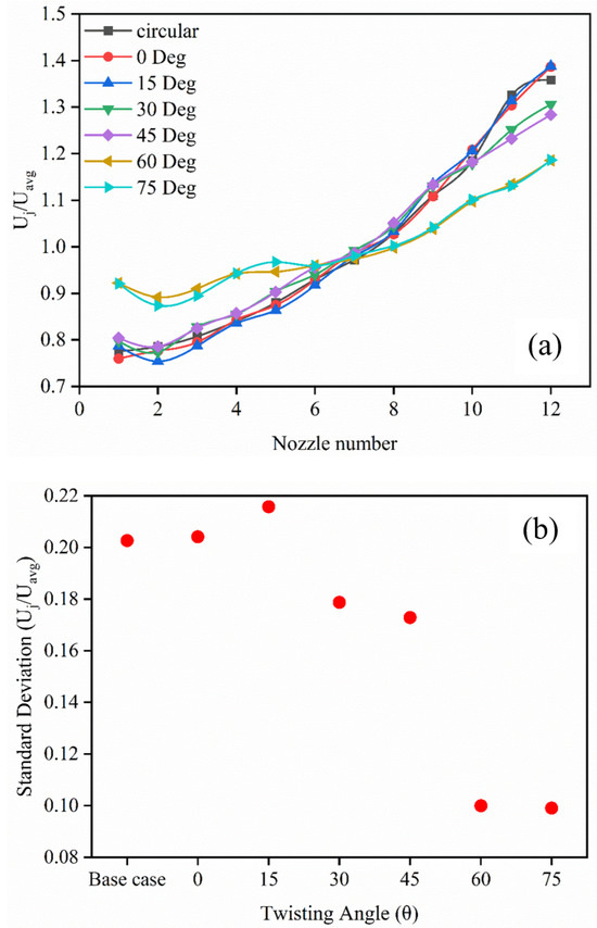
Figure 7.
Jet velocities averaged over each nozzle, normalized by the overall nozzle average, for all cases. (a) Mean jet velocity trends along the nozzle rows; (b) Standard deviation of jet velocities by twist angle.
For the base case (circular nozzle), , and , adding an insert or a small twist does not significantly change the average nozzle velocities along the streamwise direction. This is because the nozzle area remains constant and the additional flow resistance from the insert or mild twist is not enough to affect the jet velocities substantially.
Interestingly, with increasing swirl intensity, fluid flow through the initial nozzles increases, while it decreases for the later ones. At the highest twist angles ( and ), the jet velocities along the streamwise direction become more uniform and flatter compared to other cases. Figure 7b presents the standard deviation of these average velocities, showing the lowest variation for the highest twist angles ( and ).
Figure 8 displays the Nusselt number contours at the target surface for the base case and for twisted inserts with , , , , , and . In the base case, the first five jets produce rings of high Nusselt numbers around the stagnation zones. This characteristic ring of enhanced heat transfer stretches downstream but eventually fades, as an increasing proportion of the jet fluid is redirected into the crossflow. This secondary peak—a well-studied feature of impinging jet flow also reflects good agreement between the chosen turbulence model and established literature [24].
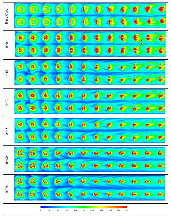
Figure 8.
Nusselt number contours at the target surface for all tested cases, capturing the impact of swirl and crossflow on local heat transfer.
In contrast, this secondary peak is not seen in the cases with twisted inserts, since a single jet is split into multiple streams. For all insert cases, each original jet divides into four, as shown by the velocity contours in Figure 4 and Figure 6. This splitting becomes even clearer when examining the Nusselt number contours in Figure 8. The inserts increase both mixing and crossflow, especially for the upstream rows, which causes the distinct heat transfer patterns from each jet to merge more rapidly in the spanwise direction—most noticeably for , , and .
For larger twist angles, the downstream heat transfer peaks do not follow a predictable split or pattern and tend to merge quickly. At the highest swirl intensities ( and ), the downstream heat transfer peaks take on a mushroom-like shape, resulting from the combined effects of strong swirl and crossflow.
Figure 9 shows the normalized local Nusselt number at the impinging region along the streamwise direction for all tested cases. The red dashed line represents the moving average, which helps track the position of heat transfer peaks as they shift from one row of holes to the next.
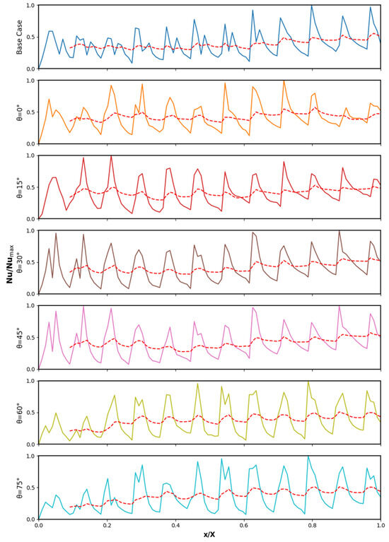
Figure 9.
Normalized local Nusselt number in the streamwise direction along with the moving average (red dashed line), highlighting variations in peak heat transfer with different swirl intensities and insert configurations.
In the base case, multiple peaks in the local Nusselt number are visible for the initial holes, but these secondary peaks disappear in the last four jets. This pattern indicates secondary heat transfer peaks in the wall jet region for non-swirling impinging jets. Downstream, the peak heat transfer is generally lower than upstream, but the addition of an insert and moderate swirl increases downstream heat transfer—except at the highest swirl angles ( and ). For these high swirl cases, the first three rows of holes have the lowest Nusselt number peaks, but from the fourth row onward, the peaks improve and become more consistent.
The difference between heat transfer peaks is smallest for and , resulting in the most uniform heat transfer out of all cases.
Figure 10 displays the normalized local Nusselt number distribution in the spanwise direction for rows 1, 6, and 12 across all cases. In the base case, the secondary heat transfer peak stands out clearly and is nearly symmetric, contrasting with the streamwise direction. However, when an insert and its twist are introduced, the secondary peaks become less pronounced, and the profiles lose their symmetry.
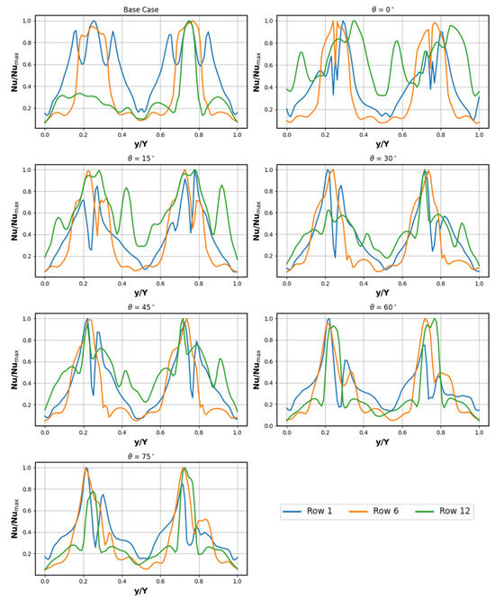
Figure 10.
Normalized local Nusselt number in the spanwise direction for selected rows, showing the impact of insert and swirl angle on secondary heat transfer peaks and uniformity.
Through all rows, the base case consistently shows distinct Nusselt number peaks. At high swirl intensities ( and ), the Nusselt number profile tends to flatten. For moderate twist angles (, , and ), the distribution is also flatter, with less prominent peaks. As observed previously in Figure 9, Figure 10 confirms that the heat transfer becomes most uniform at and .
5. Conclusions
This study used computational fluid dynamics to examine how swirling impinging jet arrays, created by inserting twisted tapes at various angles, affect heat transfer and surface temperature in gas turbine combustor liner cooling. Six nozzle inserts with twisting angles from to , as well as a simple non-swirling nozzle, were tested to produce a range of swirl intensities. The results provide several key insights:
- Low and moderate swirl inserts had minimal impact on the average jet velocity across the nozzles. However, high swirl angles (, ) produced a flatter velocity profile with reduced local velocity variations.
- Increased swirl intensity led to stronger mixing and more pronounced crossflow, which weakened the impinging jet structure. This resulted in less defined impingement and wall jet regions, and produced flatter, less pronounced heat transfer peaks.
- At high swirl angles ( and ), jets from the downstream holes were unable to reach the target surface, decreasing heat transfer effectiveness in these zones.
- Moderate swirl angles ( and ) yielded the most uniform and consistent peak Nusselt numbers across the nozzle array. This indicates optimal heat transfer performance at these twisting angles.
The findings of this study are specific to the tested combustor liner configuration and should not be generalized to other designs or operating conditions. Flow parameters were held constant to isolate swirl effects; influences such as Reynolds number and cooling hole geometry were not examined and will be the subject of future research. Further work will include detailed steady and transient LES analyses at 15° and 30° swirl angles to clarify the mechanisms behind their improved cooling performance [44].
Author Contributions
Conceptualization, M.I.; methodology, M.I. and M.H.B.; software, M.I.; validation, M.I. and M.H.B.; formal analysis, M.I.; investigation, M.I.; resources, M.I.; data curation, M.I.; writing—original draft preparation, M.I. and M.H.B.; writing—review and editing, M.I., M.H.B. and F.H.; visualization, M.I.; supervision, M.I., M.H.B. and F.H. All authors have read and agreed to the published version of the manuscript.
Funding
This research received no external funding.
Institutional Review Board Statement
This study was conducted in accordance with the ethical guidelines and research standards of the Dyson Institute of Engineering and Technology, and in compliance with relevant UK research integrity and ethics policies. All procedures followed best practices to ensure data integrity, transparency, and scientific rigor. Approval for publication of this work has been granted by the Dyson Ltd. Legal team.
Data Availability Statement
Research data is available upon reasonable request.
Conflicts of Interest
The authors declare no conflicts of interest.
Abbreviations
The following abbreviations are used in this manuscript:
| CFD | Computational Fluid Dynamics |
| RANS | Reynolds Average Navier Stokes |
| DNS | Direct Numerical Simulations |
| GCI | Grid Convergence Index |
References
- Choi, M.H.; Kim, J.; Jo, H.; Kim, H. Gas Turbine Combustor Liner Temperature Measurement Using 2D Two-Colour Pyrometry. Case Stud. Therm. Eng. 2025, 107118. [Google Scholar] [CrossRef]
- Shen, W.; Wang, S.; Liang, X. Effect of Impellers on the Cooling Performance of a Radial Pre-Swirl System in Gas Turbine Engines. Aerospace 2024, 11, 187. [Google Scholar] [CrossRef]
- Ji, C.; Shi, W.; Ke, E.; Cheng, J.; Zhu, T.; Zong, C.; Li, X. Numerical Investigations on the Effects of Dome Cooling Air Flow on Combustion Characteristics and Emission Behavior in a Can-Type Gas Turbine Combustor. Aerospace 2024, 11, 338. [Google Scholar] [CrossRef]
- Shi, L.; Wu, P.; Huang, H.; Wang, C.; Tan, X.; Shen, Y.; Song, J. Impact of Swirling Flow on the Overall Cooling Effectiveness and TBCs Insulation Characteristics of Turbine Vane. Coatings 2023, 13, 1863. [Google Scholar] [CrossRef]
- International Energy Agency. Energy Technology Perspectives; IEA: Paris, France, 2023. [Google Scholar]
- European Union. Industrial Emissions Directive (IED). Directive 2010/75/EU. Available online: https://eur-lex.europa.eu/eli/dir/2010/75/oj/eng (accessed on 10 July 2024).
- Xu, L.; Hu, N.; Lin, H.; Xi, L.; Li, Y.; Gao, J. A Review of Flow Field and Heat Transfer Characteristics of Jet Impingement from Special-Shaped Holes. Energies 2024, 17, 4510. [Google Scholar] [CrossRef]
- Liu, Y.; Sun, X.; Sethi, V.; Nalianda, D.; Li, Y.-G.; Wang, L. Review of Modern Low Emissions Combustion Technologies for Aero Gas Turbine Engines. Prog. Aerosp. Sci. 2017, 94, 12–45. [Google Scholar] [CrossRef]
- Chowdhury, T.S.; Mohsin, F.T.; Tonni, M.M.; Mita, M.N.H.; Ehsan, M.M. A Critical Review on Gas Turbine Cooling Performance and Failure Analysis of Turbine Blades. Int. J. Thermofluids 2023, 18, 100329. [Google Scholar] [CrossRef]
- Krewinkel, R. A Review of Gas Turbine Effusion Cooling Studies. Int. J. Heat Mass Transf. 2013, 66, 706–722. [Google Scholar] [CrossRef]
- Tanimura, S.; Nose, M.; Ishizaka, K.; Takiguchi, S.; Rodriguez, J. Advanced Dry Low NOx Combustor for Mitsubishi G Class Gas Turbines. In Proceedings of the ASME Turbo Expo 2008: Power for Land, Sea, and Air, Berlin, Germany, 9–13 June 2008; pp. 607–615. [Google Scholar] [CrossRef]
- Li, Z.; Xie, P.; Zeng, Q.; Chen, X. Study of Tangential Effusion Cooling of a Combustor Liner. Processes 2023, 11, 2433. [Google Scholar] [CrossRef]
- Xie, R.; Wang, H.; Xu, B.; Wang, W. A Review of Impingement Jet Cooling in Combustor Liner. In Proceedings of the ASME Turbo Expo 2018: Turbomachinery Technical Conference and Exposition, Oslo, Norway, 11–15 June 2018. [Google Scholar] [CrossRef]
- Lu, X.; Xiao, Y.; Ge, B.; Zang, S. Numerical Investigation on the Influence of Local Porosity on Effusion Cooling Characteristics in a Swirl-Stabilized Combustor. Appl. Therm. Eng. 2025, 268, 125952. [Google Scholar] [CrossRef]
- Wang, J.; Zhang, C.; Liu, X.; Song, L.; Li, J. Experimental and Numerical Investigation on the Film Cooling Performance of Cylindrical Hole and Fan-Shaped Hole with Vortex Generator Fed by Crossflow. Int. J. Heat Mass Transf. 2022, 187, 122560. [Google Scholar] [CrossRef]
- Wang, W.; Cui, J.; Qu, S. Effects of Hole Arrangement and Trenched Hole on Multirow Film Cooling. AIP Adv. 2022, 12, 045205. [Google Scholar] [CrossRef]
- Lutum, E.; Johnson, B.V. Influence of the Hole Length-to-Diameter Ratio on Film Cooling with Cylindrical Holes. J. Turbomach. 1999, 121, 209–216. [Google Scholar] [CrossRef]
- Andreini, A.; Facchini, B.; Picchi, A.; Tarchi, L.; Turrini, F. Experimental and Theoretical Investigation of Thermal Effectiveness in Multiperforated Plates for Combustor Liner Effusion Cooling. J. Turbomach. 2014, 136, 091003. [Google Scholar] [CrossRef]
- Andrews, G.E. Ultra-Low Nitrogen Oxides (NOx) Emissions Combustion in Gas Turbine Systems. In Modern Gas Turbine Systems; Woodhead Publishing: Cambridge, UK, 2013; pp. 715–790. [Google Scholar]
- Ikhlaq, M.; Al-Abdeli, Y.M.; Khiadani, M. Flow and Heat Transfer Characteristics of Turbulent Swirling Impinging Jets. Appl. Therm. Eng. 2021, 196, 117357. [Google Scholar] [CrossRef]
- Ahmed, Z.U.; Al-Abdeli, Y.M.; Guzzomi, F.G. Heat Transfer Characteristics of Swirling and Non-Swirling Impinging Turbulent Jets. Int. J. Heat Mass Transf. 2016, 102, 991–1003. [Google Scholar] [CrossRef]
- Zuckerman, N.; Lior, N. Impingement Heat Transfer: Correlations and Numerical Modeling. J. Heat Transf. 2005, 127, 544–552. [Google Scholar] [CrossRef]
- Zuckerman, N.; Lior, N. Jet Impingement Heat Transfer: Physics, Correlations, and Numerical Modeling. Adv. Heat Transf. 2006, 39, 565–631. [Google Scholar]
- Ikhlaq, M.; Al-Abdeli, Y.M.; Khiadani, M. Transient Heat Transfer Characteristics of Swirling and Non-Swirling Turbulent Impinging Jets. Exp. Therm. Fluid Sci. 2019, 109, 109917. [Google Scholar] [CrossRef]
- Liu, K.; Zhang, Q. A Novel Multi-Stage Impingement Cooling Scheme-Part I: Concept Study. J. Turbomach. 2020, 142, 121008. [Google Scholar] [CrossRef]
- Huber, A.M.; Viskanta, R. Convective Heat Transfer to a Confined Impinging Array of Air Jets with Spent Air Exits. J. Heat Transf. 1994, 116, 570–576. [Google Scholar] [CrossRef]
- Goodro, M.; Park, J.; Ligrani, P.; Fox, M.; Moon, H.K. Effect of Hole Spacing on Jet Array Impingement Heat Transfer. In Proceedings of the ASME Turbo Expo 2007: Power for Land, Sea, and Air, Montreal, QC, Canada, 14–17 May 2007; pp. 963–976. [Google Scholar] [CrossRef]
- Unnikrishnan, U.; Yang, V. A Review of Cooling Technologies for High Temperature Rotating Components in Gas Turbine. Propul. Power Res. 2022, 11, 293–310. [Google Scholar] [CrossRef]
- Da Soghe, R.; Bianchini, C.; D’Errico, J.; Tarchi, L. Effect of Temperature Ratio on Jet Impingement Heat Transfer in Active Clearance Control Systems. J. Turbomach. 2019, 141, 081009. [Google Scholar] [CrossRef]
- Liu, K. Heat Transfer Characteristics of Triple-Stage Impingement Designs and Their Application for Industrial Gas Turbine Combustor Liner Cooling. Int. J. Heat Mass Transf. 2021, 172, 121174. [Google Scholar] [CrossRef]
- Debnath, S.; Khan, M.H.U.; Ahmed, Z.U. Turbulent Swirling Impinging Jet Arrays: A Numerical Study on Fluid Flow and Heat Transfer. Therm. Sci. Eng. Prog. 2020, 19, 100580. [Google Scholar] [CrossRef]
- Chang, S.W.; Hsieh, M.F.; Cai, W.L.; Shen, H.D. Detailed Heat Transfer Measurements of Impinging Swirling and Non-Swirling Jet Arrays Emitted from Grooved Orifice Plate. Chem. Eng. Process. Process Intensif. 2020, 149, 107820. [Google Scholar] [CrossRef]
- Wannassi, M.; Monnoyer, F. Fluid Flow and Convective Heat Transfer of Combined Swirling and Straight Impinging Jet Arrays. Appl. Therm. Eng. 2015, 78, 62–73. [Google Scholar] [CrossRef]
- Biroun, M.H.; Taghipour, J.; Ikhlaq, M.; Howarth, J.; Mazzei, L.; Fu, Y.-Q. Energy dissipation mechanisms during droplet impact on superhydrophobic surfaces. Phys. Fluids 2025, 37, 052107. [Google Scholar] [CrossRef]
- Chou, P.Y. On Velocity Correlations and the Solutions of the Equations of Turbulent Fluctuation. Quart. Appl. Math. 1945, 3, 38–54. [Google Scholar] [CrossRef]
- Menter, F.R. Two-Equation Eddy-Viscosity Turbulence Models for Engineering Applications. AIAA J. 1994, 32, 1598–1605. [Google Scholar] [CrossRef]
- ANSYS, Inc. ANSYS® Fluent Theory Guide; Release 2024 R1; ANSYS, Inc.: Canonsburg, PA, USA; Available online: https://www.ansys.com/resource-library/fluent/fluent-theory-guide (accessed on 30 September 2025).
- Liu, Y.; Guo, R.; Cai, X.; Yan, R.; Zou, Y.; Zhou, B. Breeding Properties Study on High-Power Thorium Molten Salt Reactor. J. Nucl. Eng. Radiat. Sci. 2019, 5, 011003. [Google Scholar] [CrossRef]
- Saravanamuttoo, H.I.H.; Rogers, G.F.C.; Cohen, H. Gas Turbine Theory, 5th ed.; Pearson Education: Harlow, UK, 2001. [Google Scholar]
- Celik, I.B.; Ghia, U.; Roache, P.J.; Freitas, C.J.; Coleman, H.; Raad, P.E. Procedure for Estimation and Reporting of Uncertainty Due to Discretization in CFD Applications. J. Fluids Eng. Trans. ASME 2008, 130, 078001. [Google Scholar] [CrossRef]
- Ikhlaq, M.; Al-Abdeli, Y.M.; Khiadani, M. Nozzle Exit Conditions and the Heat Transfer in Non-Swirling and Weakly Swirling Turbulent Impinging Jets. Heat Mass Transf. 2020, 56, 269–290. [Google Scholar] [CrossRef]
- Roache, P.J. Perspective: A Method for Uniform Reporting of Grid Refinement Studies. J. Fluids Eng. 1994, 116, 405–413. [Google Scholar] [CrossRef]
- Florschuetz, L.W.; Metzger, D.E.; Truman, C.R. Jet Array Impingement with Crossflow-Correlation of Streamwise Resolved Flow and Heat Transfer Distributions; NASA Contractor Report 3373; NASA: Hanover, MD, USA, 1981. [Google Scholar]
- Ikhlaq, M.; Al-Abdeli, Y.M.; Khiadani, M. Methodology for Spatially Resolved Transient Convection Processes Using Infrared Thermography. Exp. Heat Transf. 2021, 34, 269–292. [Google Scholar] [CrossRef]


Disclaimer/Publisher’s Note: The statements, opinions and data contained in all publications are solely those of the individual author(s) and contributor(s) and not of MDPI and/or the editor(s). MDPI and/or the editor(s) disclaim responsibility for any injury to people or property resulting from any ideas, methods, instructions or products referred to in the content. |
© 2025 by the authors. Licensee MDPI, Basel, Switzerland. This article is an open access article distributed under the terms and conditions of the Creative Commons Attribution (CC BY) license (https://creativecommons.org/licenses/by/4.0/).