Abstract
In the literature, there is a scarcity of studies examining the combined effects of vortex-induced vibrations (VIV) and surface roughness on a bluff body. This paper contributes to the limited studies and literature on VIV by highlighting the pronounced influence of roughness on the vortex formation modes of a circular cylinder forced to oscillate with respect to the freestream. The numerical approach utilizes a purely Lagrangian description through the discrete vortex method with a roughness model. Recent results obtained by our research group have shown that a two-dimensional roughness model is more sensitive than a simple turbulence model in capturing nonlinear multi-physics phenomena with a variety of applications in different engineering areas. In particular, the control of drag force and vortex shedding frequency can be studied based on the expected physics of viscous flow. In the present paper, the dimensionless oscillation amplitude is fixed at A/D = 0.13 (D is the outer cylinder diameter), and the cylinder forcing frequency varies in the range of 0.04 ≤ fo ≤ 0.80 at a high Reynolds number value of Re = 1.0 × 10⁵. Three relative roughness sizes are chosen, i.e., ε/D = 0.001, 0.0045, and 0.007 (ε is the average roughness). The test cases without roughness effects are compared to experimental visualizations to capture two basic anti-symmetrical modes, namely the A-I and A-IV modes, the symmetric S-I (Type-I) mode, and the Chaotic mode categorized as C-I. Our strategy to identify these wake modes verifies the synchronization between the vortex shedding frequency fCD, interpreted from temporal history of the drag force on an oscillating cylinder, and the body forcing frequency. In the test cases using the roughness model, it is possible to identify a desynchronization between the frequencies f0 and fCD as well as significant variations in the drag force. The roughness effect also provokes a regime of vortex formation, here classified as “A-IV mode with coalescence”.
1. Introduction
The study of external incompressible flows at high Reynolds numbers around bluff bodies finds many engineering applications, such as cables of suspension bridges, chimneys, heat exchanger tubes, nuclear power plants, offshore platforms, power cables, subsea pipelines, tall buildings, and so on. Flows past bluff bodies include fundamental subjects such as the occurrence of massive boundary layer separation, instability, transition, and formation of a periodic wake downstream of a solid boundary. Consequently, an underlying understanding of the fluid dynamics in flows past bluff bodies is required and challenged. The circular cylinder is the best-known representative of the bluff bodies. The occurrence of flows past a circular cylinder is common in many engineering problems; therefore, this flow configuration has been widely studied, which is also classified as a classical problem in fluid mechanics.
The analysis of this class of flow plays a key role in testing numerical algorithms. Our research group has adopted an interesting strategy aimed at developing discrete vortex methods to enhance the understanding of flow physics from a Lagrangian approach. Accurate solution of detached vortex structures is critical for different problems of bluff body aerodynamics. In this context, many previous investigators have solved fluid–structure interaction (FSI) problems using Lagrangian Vortex Methods (LVM). In a Lagrangian fashion, the major vorticity-containing regions of the flow field are discretized using computational points (discrete point vortices) moving with the fluid particles. This numerical approach avoids stability problems of explicit schemes (or cumbersome implementation of implicit schemes) and mesh refinement problems in regions of high rates of strain; all calculation is restricted to the vorticity-containing regions, and no explicit choice of the outer boundaries is required a priori; no boundary condition is required far from the solid boundaries into the fluid domain. On the other hand, the velocity field computation over the computational points demands a number of operations at each time step proportional to the square of the number of discrete point vortices present in the fluid domain during every time step. This may lead to very large CPU times if a long-time solution is performed. There is no doubt that the future LVM computations, necessary to achieve more complex flow approximations, will need to be continually strengthened with novel high-performance computing parallelism techniques and powerful algorithms [].
Recent literature records have pointed to different algorithms to reduce the computational time associated with LVM; some of them are based on improved multipole expansions [,], and others use parallel implementation with CUDA technology []. The vortex methods have also supported a neural network description of Lagrangian vortices and their interaction dynamics; the purpose was to reconstruct the high-resolution Eulerian flow field in a physically precise form [].
The mathematical background and numerical treatment of the LVM are well introduced in the literature, such as a time-stepping scheme to compute viscous effect [], vorticity diffusion [], solid boundary discretization using a panels method [], turbulence modeling [], and vorticity generation from the solid surface []. Many algorithms have been implemented to solve problems with diverse sets of characteristics, such as flows around bluff bodies including turbulence modeling, rough surface effect, wall confinement, structural vibration, and mixed convection heat transfer.
Bimbato et al. [] developed a two-dimensional rough surface model blended with large-eddy simulation (LES) theory, whose purpose was to alter the boundary layer flow and flow separation. The second-order velocity structure function model of the filtered velocity field was associated with a set of points strategically located close to the circular cylinder surface. The key idea was that the set point would inject momentum in the boundary layer, simulating surface roughness effect. A delay in the separation of the hydrodynamic boundary layer was successively captured in accordance with the expected physics for the problem. Oliveira et al. [] applied the rough surface model developed by Bimbato et al. [] to investigate circular cylinder aerodynamics in ground effect. The full cessation of the vortex shedding mechanism was captured with combined effects of wall confinement and surface roughness. However, no attempt was made by the authors to include heat transfer and structural vibration.
Narsipur et al. [] implemented a vortex method to study the perching and hovering maneuvers, which are two bio-inspired flight maneuvers presenting applicability in engineering problems, especially for small-scale uncrewed air vehicles. Zou et al. [] developed a vortex method related to an accurate and efficient dynamic model for robotic fish.
Kumar et al. [] employed the vortex method to investigate the flapping motion of a rectangular wing. The parametric dependence of kinematic parameters such as aspect ratio, asymmetric ratio, and reduced frequency on the aerodynamic performance was investigated and discussed.
Hirata et al. [] developed a LVM to investigate flows around an oscillating circular cylinder, which moved with constant velocity in a quiescent Newtonian fluid with constant properties. The authors presented a detailed study of the influence of frequency and oscillation amplitude on the aerodynamic loads and vortex shedding frequency in the lock-in regime. Wang et al. [] investigated the VIV of deepwater drilling risers in the time domain using the vortex method; the study contributed to the optimal design and engineering control of deepwater drilling risers. However, the latter two papers did not include results with surface roughness effects.
Chiaradia et al. [] incorporated the combined effects of turbulence and mixed convection heat transfer to a LVM algorithm. The work presented two examples of application, namely the problems of circular cylinder aerodynamics and airplane wake vortex behavior in the vicinity of a ground plane; however, no surface roughness effects were investigated.
The literature has also explained flows past an immovable circular cylinder in terms of the temporal history of the lift and drag coefficients, in which they oscillate in time with approximately constant amplitude []. The lift coefficient oscillates about zero with a dimensionless frequency equal to the Strouhal number, defined as St = fD/U∞, where f is the classical vortex shedding frequency forming the viscous wake behind an immovable cylinder, D is the outer cylinder diameter, and U∞ is the uniform freestream velocity. On the other hand, the drag coefficient simultaneously oscillates with a dimensionless frequency approximately equal to twice the Strouhal number. The Strouhal number presents a value approximately constant and equal to 0.19 for a large range of the Reynolds number, Re []. This behavior reveals that the incoming flow generates an oscillation motion on the cylinder surface because the vortices are alternatively shed, constructing the Von Kármán vortex street. In this case, an additional oscillation motion relative to the incoming flow can also be generated by an unsteady periodic perturbation superimposed on the uniform freestream, impacting immovable cylinder aerodynamics. In this flow condition, the flow is further controlled by both the frequency of the external oscillatory driving force, f0, and the oscillation amplitude, A. The forced oscillation technique is, therefore, able to simulate conditions in which a structure is placed in fluid flows, and flow-induced vibration (FIV) can appear as a hazard for structural safety. Vortex-induced vibration (VIV) is a type of FIV defined as the vibration caused by vortex shedding from the structure. It is necessary to design VIV suppression techniques for real-life engineering structures.
Zhao [] reviewed the most recent studies for suppressing the VIV of circular cylinders related to passive and active flow control devices. The passive flow control devices interfere with shear layer, flow separation, or viscous wake interaction. The reviewed devices were control rods, porous layers, splitters, and rough surface. On the other hand, active control devices need external energy and can induce a modification on the flow separation or viscous wake interaction. The energy requirement makes active control more costly, and the author reviewed the following devices: jet flow, rotating cylinder, and rotating control rods.
The problem of oscillatory wake formation behind a circular cylinder under streamwise oscillation motion has attracted less attention in the research community, which, however, is equally important to problems like vortex-induced vibration of transverse vibration motion, either induced or forced. In general, experimental studies of controlled forced vibration are generally conducted by water flume tests, varying oscillation amplitude and frequency. Bearman [] postulated that a cylinder under free vibration, combined with a small increase in flow velocity, will experience large changes in its oscillation amplitude, possibly accompanied by a change in the vortex formation mode. Therefore, it is more difficult to study such jumps, or transitions, for a cylinder under the condition of free vibration. On the other hand, controlled forced vibration of a cylinder requires a large number of runs to more precisely map the conditions under which energy transfers from the fluid to the body. It is important to comment that the majority of the numerical studies of VIV control have been performed under low Reynolds number laminar flow regimes, more precisely for Re ≤ 200. On the contrary, the Reynolds numbers fall within the turbulent flow regime in most water and wind engineering applications.
Ongoren and Rockwell [] experimentally investigated the vortex formation regimes of a cylinder undergoing controlled oscillations at arbitrary angle δ with respect to the freestream velocity. For most experiments, a constant value of dimensionless oscillation amplitude was chosen as A/D = 0.13 for δ = 0°, with the Reynolds number kept fixed at Re = 855. The oscillation frequency adopted by the authors is here redefined as f0, and the natural vortex-shedding frequency from corresponding immovable cylinder is also redefined as f []. The authors considered a frequency relation in the range 0.5 ≤ f0/f ≤ 4.0 and identified two basic modes, which are the symmetric and anti-symmetric vortex formation. The work classified these two basic modes into five submodes: S mode for the symmetric formation regime, and A-I, II, III, IV modes for the anti-symmetric formation regime. The symmetric S mode appeared at all excitation angles δ, except at δ = 90°. The anti-symmetric A-II, A-III, and A-IV modes exhibited period (i.e., one body oscillation cycle) doubling relative to the classical Kármán street formation of the anti-symmetric A-I mode. Furthermore, the A-III and A-IV modes present formation of counter-rotating vortex pairs. The A-III and A-IV modes appeared only for δ = 0°. Interestingly, the A-II mode was captured only for δ ≠ 0°. In general, these modes either can be phase-locked with the cylinder oscillatory motion, or they can compete and switch between symmetric and anti-symmetric vortex formation. The authors did not include investigation about rough surface effects.
In general, previous studies of the flow behind a streamwisely oscillating cylinder have reported six modes, i.e., A-I, A-II, A-III, A-IV, S-I, and S-II, in which the maximum oscillation amplitude is about (A/D)max < 0.8 and the maximum forcing frequency is about (f0/f)max < 3. Additionally, Hu et al. [] studied the wake modes behind a circular cylinder under streamwise forced oscillation at Reynolds numbers in the range of Re = 360–460, which are visualized using the laser-induced fluorescence technique. The forcing frequency f0/f ranged from 0.0 to 6.85, and the amplitude A/D was investigated for 0.2, 0.5, and 1.0. Typical flow modes reported by Xu et al. [] were also observed by the authors, such as asymmetric modes, symmetric modes, and Chaotic modes. Three rarely reported modes in previous numerical studies, C-I, C-II, and S-III, were confirmed by Hu et al. []. These modes typically occur at higher amplitude and/or f0 ranges than those investigated in previous works. The lock-in regime at a fixed amplitude generally follows the order of S-I (Type-I) mode, A modes, S-I (Type II) mode, and S-II/S-III and C modes (Chaotic modes) as the time invariant f0 increases. In general, the different vortex formation modes have been captured in terms of the following control parameters: forcing amplitude, body forcing frequency, and Reynolds number based on the freestream velocity. However, the roughness effect was not reported by all authors. Of particular interest for the present work, the S-I (Type I) mode is identified when a pair of vortices is shed in phase from both sides of the cylinder during one oscillation cycle and immediately coalesce in the near wake region. And, the Chaotic mode C-I is characterized when small-scale vortices form, lose their stability quickly, and coalesce to form vortices of larger scale [].
This paper contributes to the VIV literature by investigating two-dimensional, incompressible, unsteady flow past a rough cylinder under sinusoidal oscillation motion in a streamwise direction. There is limited data related to LVM with surface roughness effects to simulate flows past a circular cylinder forced to oscillate with respect to the freestream. In the past, our research group has reported that the use of two-dimensional LES-based turbulence modeling is necessary to stabilize the numerical solution and enables the development of rough surface models [,,]. The advantage of combining the LES model and LVM is that the concept of differences of velocity (velocity fluctuations) is used instead of derivatives (rates of deformation). The local eddy viscosity coefficient is computed over every discrete point vortex along with the vorticity diffusion process during the time stepping. In other words, that computation considers the small-scale effect of the flow through the concept of differences in velocity among discrete point vortices. The results contribute to the knowledge of the context in which roughness effects importantly modify the vortex formation modes synchronized with the forced oscillation motion imposed on the body surface over the frequency ratio f0/fCD = 1.0. The roughness model developed by Bimbato et al. [] is once again validated in the present study.
2. Mathematical Formulation
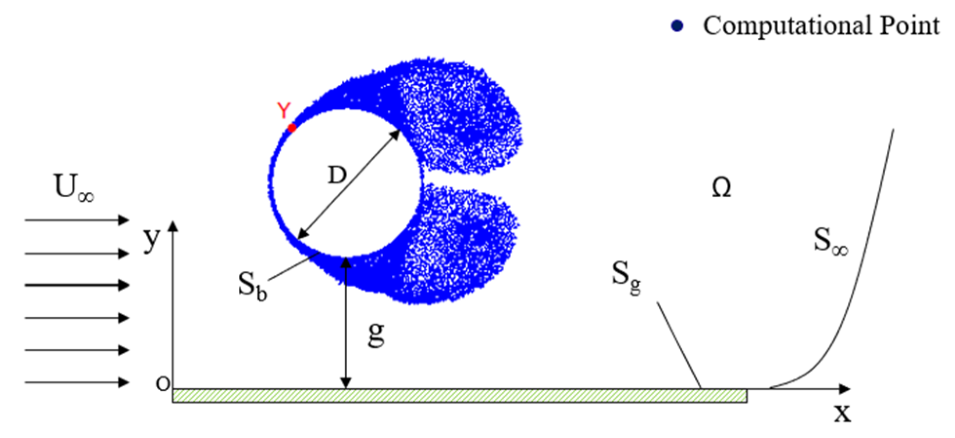
Figure 1 illustrates the flow past a circular cylinder of outer diameter D, immersed in a semi-infinite fluid domain Ω with a uniform flow of freestream velocity U∞. The semi-infinite fluid domain is defined by surface S = Sb ∪ Sg ∪ S∞, where Sb is the cylinder surface, Sg is the ground plane surface, and S∞ defines the far away fluid boundary. The gap between the cylinder bottom and the ground plane is defined by g. In a Lagrangian manner, the vorticity generated from solid surfaces is discretized and represented by computational points, so-called nascent discrete point vortices. In LVM, these computational points are commonly created on solid surfaces at every time step in a typical numerical simulation.
Figure 1.
Problem geometry and definitions.
In order to non-dimensionalize all the quantities in the general formulation, D is adopted as the representative length and U∞ is chosen as the representative velocity. The dimensionless time is then defined by tU∞/D.
In Figure 1, the ground plane is adopted as the inertial frame from which the circular cylinder is forced to oscillate with respect to the freestream at a large gap-to-diameter ratio, namely g/D = 1000. Thus, there is no interference of wall confinement over the oscillatory motion of the circular cylinder.
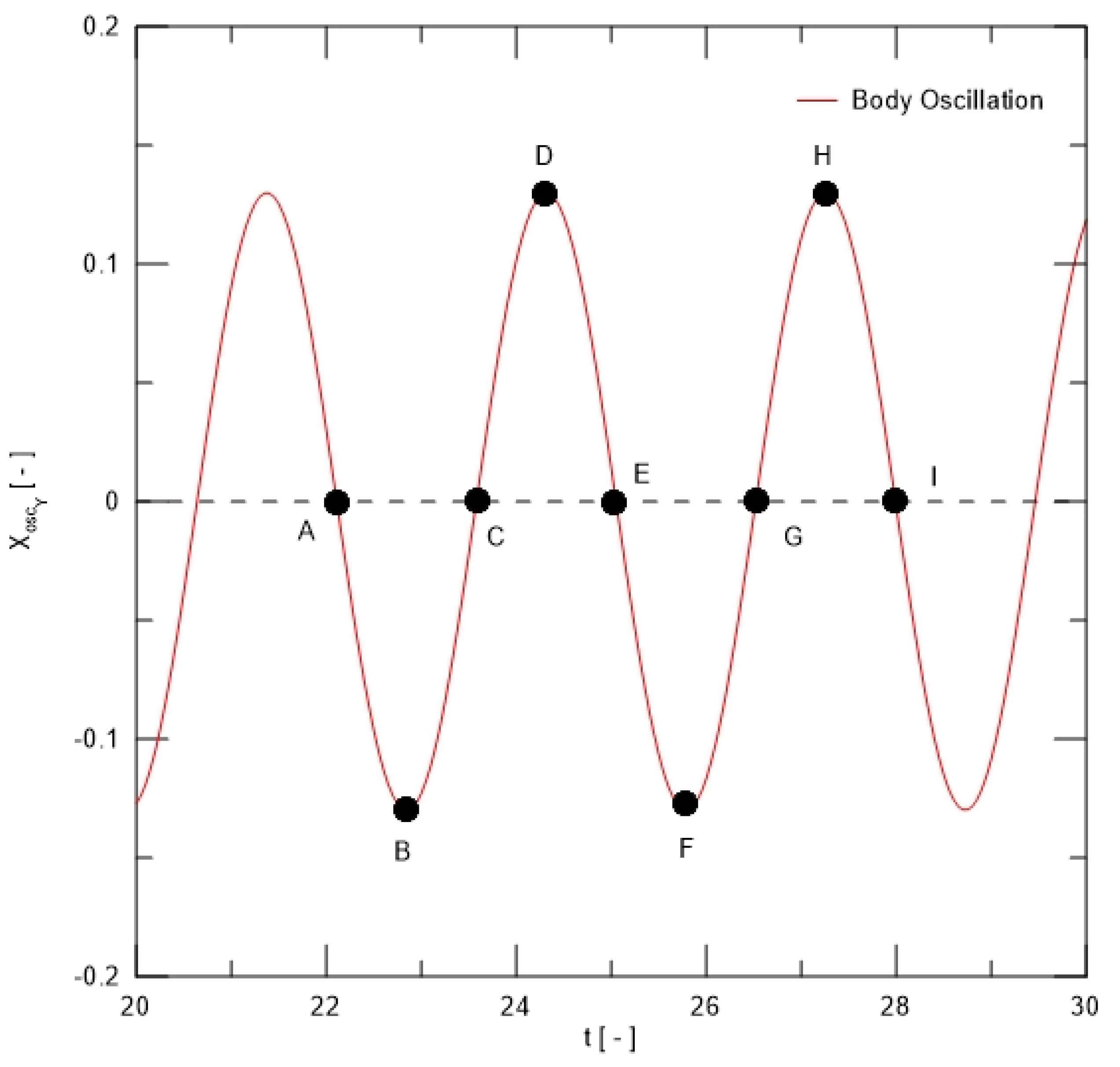
Figure 2 describes the oscillatory motion of point Y placed at the cylinder surface; this point is also identified in Figure 1. The instantaneous position and velocity of point Y are defined as follows, respectively:
where A is the oscillation amplitude and f0 is the body oscillation frequency.
Figure 2.
Sketch of an in-line oscillating circular cylinder.
The flow is assumed to be incompressible and two-dimensional, and the fluid is assumed to be Newtonian with constant kinematic viscosity ν. The unsteady flow developed from the boundary layer separation on the cylinder surface generates an oscillatory wake downstream of the body. The governing equations for the problem are the vorticity transport equation and pressure Poisson equation. The vorticity transport equation is obtained by taking the curl of the Navier–Stokes equations including some algebraic manipulations, which also eliminates the pressure term. In two dimensions, this equation can be written as follows [,,]:
The pressure Poisson equation is obtained by taking the divergence of the Navier–Stokes equations including some algebraic manipulations, resulting in the following differential equation:
In Equations (3) and (4), is the filtered velocity field, is the filtered pressure field, and is the only non-zero component of the filtered vorticity field (in a direction normal to the plane of flow). The vorticity is a vector quantity, represented by the curl of the velocity field. A “filtered field” is interpreted as the component of the field that remains after removing the small scales related to turbulent motions through a filtering process []. The eddy viscosity coefficient is then identified by νt, the Reynolds number, defined as follows:
The flow is started impulsively from rest. The impermeability and no-slip boundary conditions are imposed on the cylinder surface (at r = D/2 = 0.5) as follows, respectively:
where n and t are unit vectors normal and tangential to the cylinder surface, respectively. For the ground plane, only the impermeability condition is imposed (at y = 0 and 0 ≤ x ≤ 10D).
Additionally, the perturbation in the semi-infinity fluid domain due to the surfaces Sb and Sg (Figure 1) fades away, that is:
3. Algorithm of the Lagrangian Vortex Method
The left-hand side of the vorticity transport equation, Equation (3), carries all the information needed for the vorticity advection, while the right-hand side governs the vorticity diffusion and turbulent motions. Chorin [] proposed the viscous splitting algorithm, which, for the same time stepping Δt of the numerical simulation, establishes that the vorticity advection is governed by the following equation in a Lagrangian manner:
The vorticity diffusion and turbulent motions are additionally governed by:
where Equations (9) and (10) converge to the original Equation (3) when the time stepping Δt tends to zero.
In the present numerical approach, a cloud of NV discrete point vortices, each of constant strength Γk and core size σ0k, represents the instantaneous vorticity field in the following form []:
3.1. Generation of Source Panels and Discrete Point Vortices
The cylinder and ground plane surfaces are discretized and represented by flat panels. Every flat panel has a central point, the so-called pivotal point, where the boundary conditions of the problem (Equations (6) and (7)) must be more precisely imposed.
The panels method [] is employed to represent the solid surfaces of the problem, where NP source panels are generated during every time step; the source strength per panel length is assumed as constant. The source strengths are obtained by solving a linear system of algebraic equations to ensure the impermeability condition (Equation (6)) and mass conservation on every pivotal point due to the incident flow, the source panels, the vortex cloud, and the cylinder oscillation velocity (Equation (2)).
The vorticity flow is represented by proper distribution of discrete point vortices. The strength of the nascent discrete point vortices is obtained by imposing the no-slip condition (Equation (7)) and the global circulation conservation on every pivotal point due to the incident flow, the source panels, the vortex cloud, and the cylinder oscillation velocity (Equation (2)).
Thus, the panels method is combined with the point-vortex representation (vortex cloud) and uniform flow of freestream velocity to construct a flow field over discrete point vortices, which characterizes the Lagrangian description.
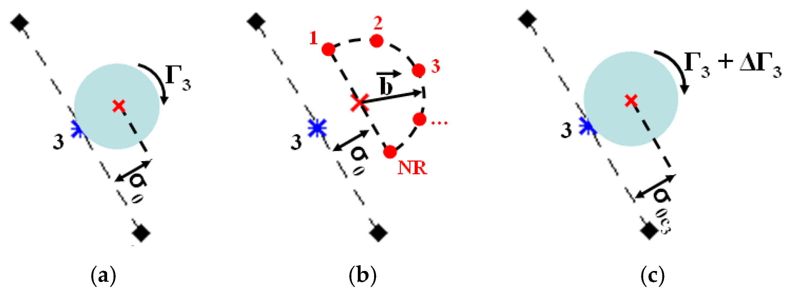
Figure 3a exemplifies the instantaneous generation of a discrete point vortex from the cylinder surface with no roughness model. Additionally, the center of every nascent discrete point vortex is placed at the shedding point. The viscous effect is confined within the vortex core, σ0.
Figure 3.
Example of instantaneous shedding of a discrete point vortex from the third flat panel representing the cylinder surface: (a) with no roughness model; (b) momentum injection model; and (c) with roughness model.
Figure 3b exemplifies the key idea of the roughness model, which is inspired by momentum injection into the boundary layer during the vorticity shedding from a flat panel. The roughness model modifies the viscous core, σ0, and the vortex strength, Γv, of every nascent discrete point vortex. The three steps necessary to apply the roughness are as follows: (i) the vortex strength, Γv, is obtained by solving a linear system of algebraic equations to ensure the non-slip condition on every pivotal point because of incident flow, source panels, vortex cloud, and oscillatory motion of the cylinder; (ii) a semicircle of radius , centered at the shedding point, is necessary to evaluate turbulent activities into the boundary layer, where ε represents the interference of a selected average roughness height []; and (iii) the vortex strength, Γv, must be corrected by solving once more the linear system of algebraic equations to ensure the non-slip condition. Figure 3c illustrates the effective creation and shedding of a discrete point vortex including the idea of momentum injection into the boundary layer.
Bimbato et al. [] adopted a numerical approach to capture the velocity differences among the centere of the ith shedding point and NR = 21 rough points, as sketched in Figure 3b, where the second-order velocity structure function model of the filtered velocity field is given as follows:
where the multiplication factor (1 + ε) defines the kinetic energy gain associated with the momentum injection. After some numerical tests, Bimbato et al. [] defined a set of NR = 21 rough points to compute the average velocity differences required to calculate the second-order velocity structure function of the filtered velocity field.
The viscous core is corrected in the following form []:
3.2. The Velocity Field
The instantaneous velocity field is computed over every discrete point vortex from three contributions, namely the incident flow, source panels, and vortex cloud.
The contribution of the uniform flow of freestream velocity over the kth discrete point vortex is easily computed as follows:
The contribution of the solid surfaces, via source panels, over the kth discrete point vortex is obtained as follows []:
where n represents the two components of the velocity vector, NP is the total number of source panels, is the uniform source density, and defines the nth component of the velocity induced at the kth discrete point vortex by the ith source panel.
The vortex cloud contribution is evaluated through the Biot–Savart law. Thus, the velocity induced over the kth discrete point vortex is computed as follows []:
where n represents the two components of the velocity vector, NV is the total number of discrete point vortices, is the strength of every discrete point vortex, and corresponds to the nth component of the velocity induced by the jth discrete point vortex (of unitary strength) at the position of the kth discrete point vortex.
3.3. The Pressure Field
The drag and lift coefficient computation is based on Equation (4), and it starts with the following definition of stagnation pressure over every pivotal point:
where , is the static pressure, ρ is the fluid density, and is the velocity. The solution to Equation (4) is obtained in accordance with the following integral formulation []:
such that the pressure field can be calculated at fluid domain points of interest, in which for points of the fluid domain and for points over solid surfaces, is the fundamental solution to the Laplace equation, and represents the normal unit vector pointing from a solid surface to the fluid domain.
Equation (19) presents the static pressure distribution over the NP pivotal points as an unknown value. The static pressure is then obtained by solving a linear system of algebraic equations. The solution to Equation (19) also enables the computation of drag and lift coefficients as follows, respectively [,]:
where is the reference pressure far from the solid boundaries, Cpi is the pressure coefficient, represents the length of the ith flat panel, and is the anti-clockwise orientation angle of the same flat panel.
It should be noted that the pressure field is instantaneously computed only after the boundary conditions (Equations (6) and (7)) are verified over the pivotal point of every flat panel.
3.4. The Advective Problem
The advective problem is governed by Equation (9) and, therefore, the advective motion of every discrete point vortex is determined by the integration of every vortex path equation, which can be written using an explicit Euler scheme [] as follows:
where dt is interpreted as time stepping, i.e., , in which its value is evaluated from an estimate of the velocity and advective length of the flow [,,]. A purely Lagrangian description does not require the explicit treatment of advective derivatives [].
3.5. The Diffusive Problem and Turbulent Motions
The turbulent motions are considered through the concept of the local eddy viscosity coefficient, νt; see Equations (3), (10), (13) and (25). The eddy viscosity coefficient is instantaneously calculated at the position of every discrete point vortex, being defined as follows [,]:
where Ck = 1.4 is the Kolmogorov constant, σ0 is the viscous core of the ith point vortex, and is the local second-order velocity structure function of the filtered field [,], as follows:
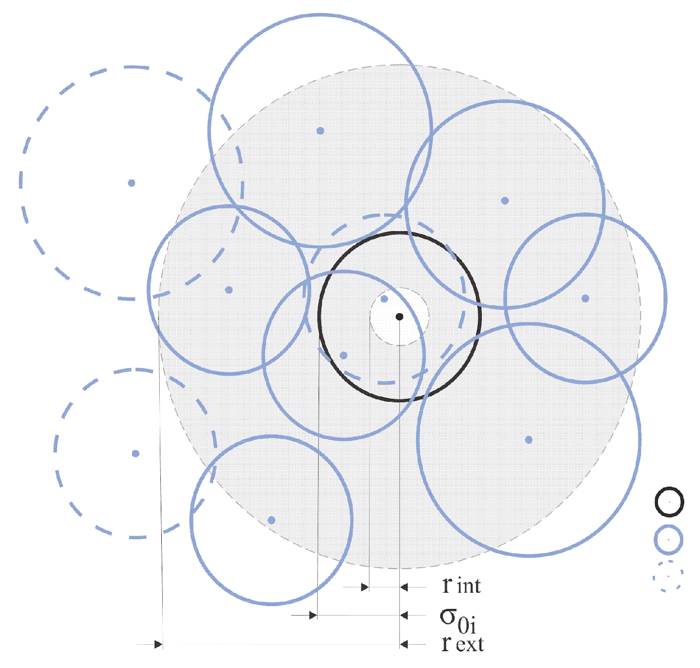
where the summation is calculated by counting the number N of discrete point vortices located inside of an annulus, where defines the distance between the center of the annulus (center of the ith viscous core under analysis) and centers of other discrete point vortices placed between the internal (rint) and the external (rext) radius of the same annulus [,], as illustrated in Figure 4.
Figure 4.
Schematic of the model of spatial average velocity calculation.
In Figure 4, the circle in black defines the viscous core of the discrete point vortex under analysis; the circles in blue with solid lines represent discrete point vortices inside of the annulus; and the circles in blue with dashed lines represent discrete point vortices not contributing to the calculation of the local second-order velocity structure function of the filtered velocity field associated with the ith viscous core related to vortex i.
The vorticity diffusion (or molecular diffusion due to the viscosity effect) is computed using a statistical technique known as the Random Walk Method (RWM). Thus, the diffusive motion of every discrete point vortex is evaluated in the following manner [,]:
where P and Q are random numbers between 0.0 and 1.0. P and Q are also random displacements with mean equal to zero and a variance given by twice the product of the kinematic viscosity and time.
The convergence of the advection and diffusion problems was previously demonstrated by Carvalho et al. [].
Finally, the LVM algorithm, described in this section, was implemented using an in-house code via parallel computing (OpenMP). The steps are as follows:
- (i)
- Initial specifications of the problem geometry (Figure 1) including NP pivotal points and starting flow.
- (ii)
- Generation of NP source flat panels to ensure the impermeability condition on pivotal points of both cylinder and ground plane surfaces including mass conservation.
- (iii)
- Generation and shedding of M discrete point vortices with no roughness model to ensure the no-slip condition only on pivotal points of the cylinder surface, including global circulation conservation.
- (iv)
- Correction for viscous core and vortex strength of all nascent discrete point vortices because of surface roughness effect; imposition of the no-slip condition (Equation (7)) and the global circulation conservation on every pivotal point due to incident flow, source panels, vortex cloud, and cylinder oscillation velocity (Equation (2)), and use of Equation (13).
- (v)
- Computation of the velocity field at every discrete point vortex in the real plane (i.e., for y > 0), as sketched in Figure 1.
- (vi)
- Computation of the distributed and integrated aerodynamic loads.
- (vii)
- Advection of the cluster of discrete point vortices.
- (viii)
- Computation of turbulent motions near every discrete point vortex.
- (ix)
- Vorticity diffusion using the RWM with LES theory.
- (x)
- Reflection of discrete point vortices that accidentally migrate inside the cylinder and ground plane.
- (xi)
- Cylinder oscillation in accordance with Equation (1).
- (xii)
- Computation of the velocity field at every pivotal point to ensure the no-slip condition and, consequently, to obtain a new generation of discrete point vortices. This computation includes the contribution of the incident flow, vortex cloud, and oscillatory motion of the cylinder (see Equation (2)).
- (xiii)
- Advance time by Δt.
4. Results
The main quantitative features of the flow past a streamwise oscillating cylinder are numerically studied at a high Reynolds number of Re = 1.0 × 10⁵. The ground plane is simulated for a gap-to-diameter ratio of g/D = 1000, since it is only used as the inertial frame, from which the circular cylinder oscillates with forcing frequency f0 ranging from 0.00 (stationary cylinder) to 0.80 and fixed forcing amplitude A/D = 0.13. The experimental visualizations reported by Ongoren and Rockwell [] and Hu et al. [] are utilized to compare the vortex formation regimes of a cylinder undergoing controlled oscillations at angle δ = 0° with respect to the freestream velocity. Relative roughness sizes ε/D ranging from 0.000 (smooth case) to 0.007 are chosen for the test cases. Bimbato et al. [] presented a complete discussion concerning the surface roughness effect on a stationary circular cylinder at g/D = 1000 using the present vortex code; therefore, these results will not be repeated here. Table 1 summarizes the main numerical results of the present study.
Table 1.
Numerical results of aerodynamic forces and vortex shedding frequency of the flow past a cylinder with forced vibration model at g/D = 1000 and Re = 1.0 × 10⁵ *.
Most numerical simulations were carried out up to dimensionless time t = 50. The main numerical parameters were validated using case I (Table 1) as reference; namely dimensionless time step Δt = 0.05, number of discrete point vortices of M = 300 to be shed at the cylinder surface during every time step, and displacement ℓ = σ0 = 0.001D (core radius) imposed during every time step to move the nascent discrete point vortex to ℓ-layer normal to the smooth cylinder surface. The time increment was validated according to Δt = 2πKϕ/N, being 0 < ϕ < 1 and N = 300 []; in this strategy, N is equal to the total number of source flat panels used to represent the cylinder surface according to the panels method []. All computations were performed at 20 ≤ t ≤ 50 to evaluate time-averaged values.
4.1. Smooth Circular Cylinder with No Forced Vibration: Formation of the Kármán Street
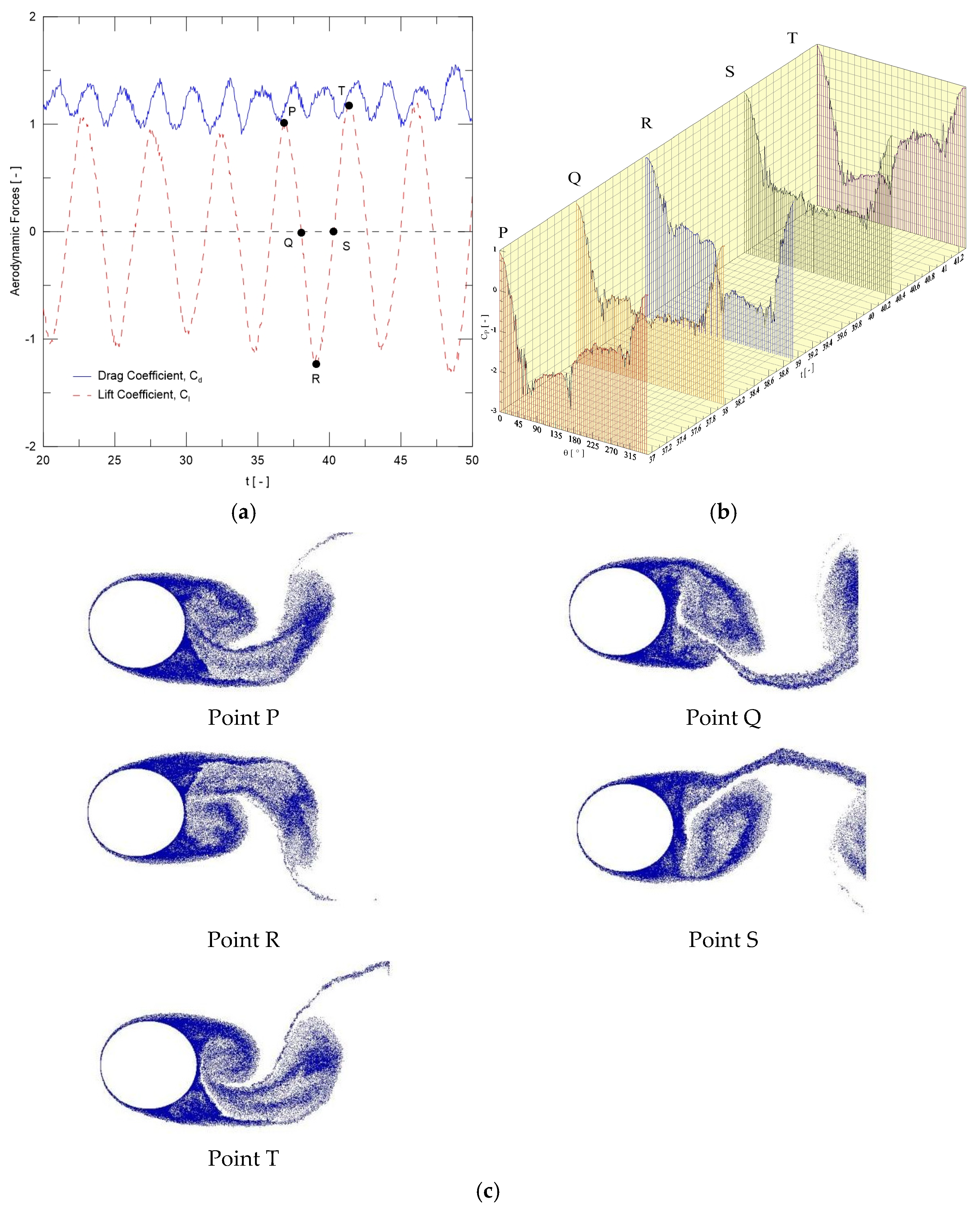
The time histories of the drag and lift coefficients are revealed in Figure 5a. It can be observed that these coefficients reach a periodic steady state after an initial numerical transient (t ≈ 20) and, subsequently, oscillate with approximately constant amplitude. The mean oscillation for the lift coefficient is about zero, with a non-dimensional frequency (Strouhal number) of 0.20. Figure 5b presents instantaneous pressure coefficient distributions related to non-dimensional times identified by points P, Q, R, S, and T, also marked in Figure 5a. Point P indicates that a clockwise vortical structure is detaching from the cylinder upper surface and moving toward the near wake, as shown in Figure 5c. Point R is about the time instant in which a counter-clockwise vortical structure is detaching from the cylinder’s lower surface to be also incorporated into the near wake. The time interval between points P and T indicates that the drag coefficient oscillates in time with twice the frequency of the lift coefficient (fCD = 0.40, as reported by case I in Table 1). The drag coefficient behavior is explained by the fact that the drag force fluctuates once for each upper and lower detaching from the cylinder surface.
Figure 5.
Temporal history of aerodynamic loads and near wake of immovable circular cylinder with no roughness model: (a) lift and drag coefficients, (b) instantaneous pressure coefficient, and (c) distribution of discrete point vortices constructing the near wake pattern for the flow.
The mean drag coefficient is around CD ≈ 1.2045 (case I in Table 1), while the experimental result from Blevins [] is CD ≈ 1.2000, with 10% uncertainty. It is well-known in the classical literature that the Strouhal number is more or less constant about St ≈ 0.19 for a smooth cylinder with no oscillatory motions at subcritical regime (300 < Re < 1.4 × 10⁵). Blevins [] reported an experimental value around St ≈ 0.19, also with 10% uncertainty, at the upper-subcritical flow regime of Re = 1.0 × 10⁵. Thus, classical von Kármán-type vortex shedding has been successfully identified using the present vortex code.
4.2. Circular Cylinder with Forced Vibration: Mode A-I and Its Desynchronization
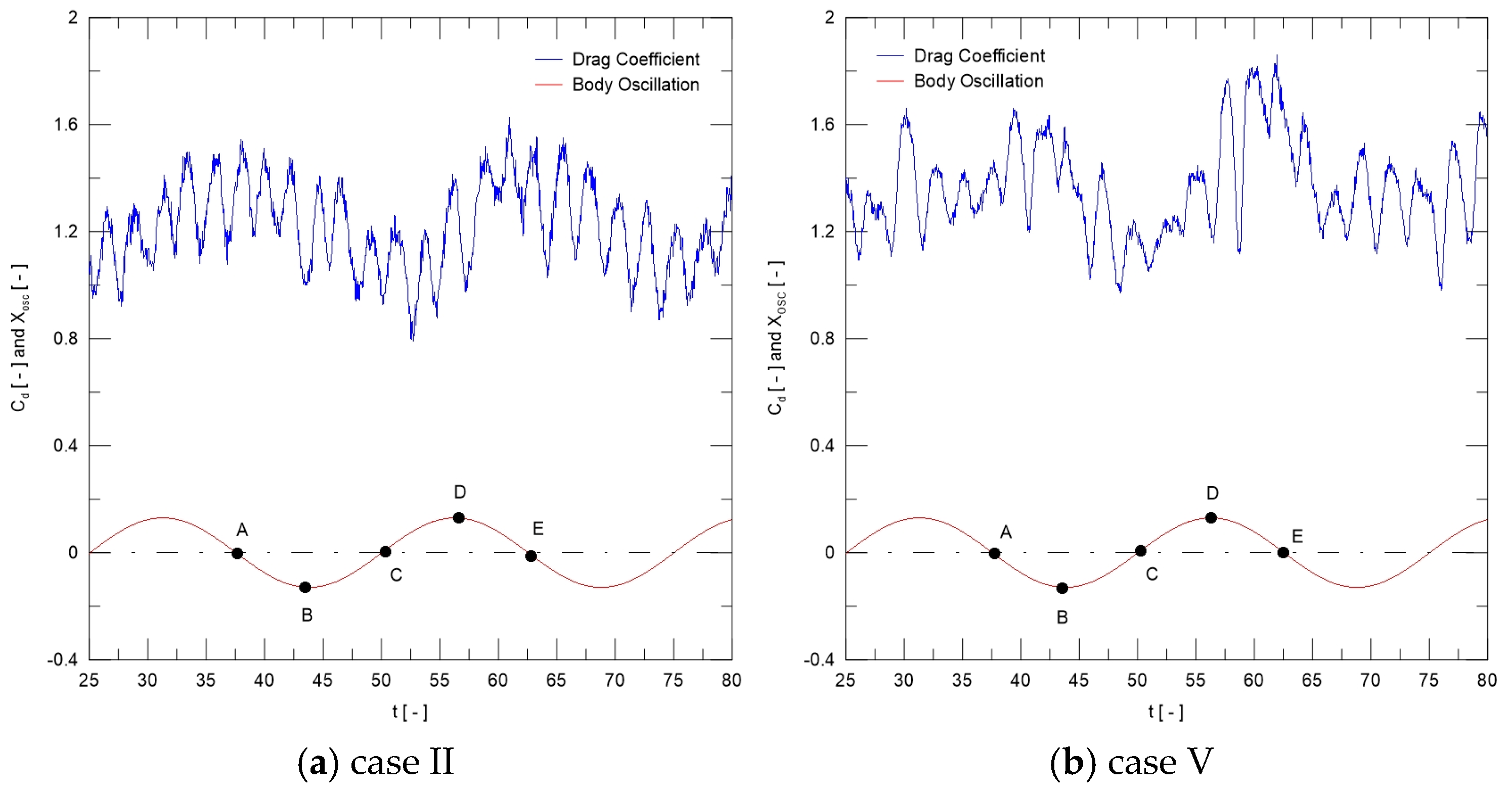
In Table 1, cases II–IV are related to the anti-symmetric A-I mode, where the vortex shedding is synchronized with the cylinder motion, i.e., f0/fCD = 1.0. Figure 6 presents the time histories for drag coefficient and motion displacement xosc(t). The curve identified as “Body Oscillation” originates from Equation (2), adopting f0 = 0.04 and A/D = 0.13. Figure 6a is related to the smooth case (ε/D = 0.000), where the cylinder is over the von Kármán large-scale vortex formation regime during one oscillation cycle starting from point A to point E, see also Figure 2. In other words, the formation of some counter-rotating vortices, characterized by two vortices rotating in opposite directions connected to each other by thin vortex sheets, is identified during one oscillation cycle of the cylinder in lock-in regime (f0/fCD = 1.0) between the time instants marked by A and E (Figure 6a).
Figure 6.
Time variation of drag coefficient and motion displacement xosc(t) for mode A-I (f0 = 0.04): (a) ε/D = 0.000, and (b) ε/D = 0.007.
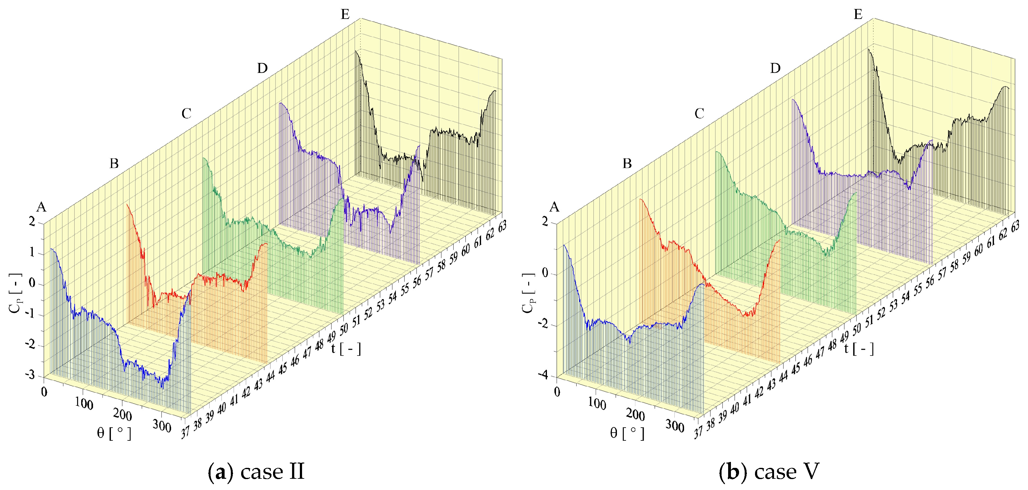
Figure 6b illustrates case V (Table 1), in which it is possible to conclude that the relative roughness size of ε/D = 0.007 has desynchronized the anti-symmetric A-I mode, since the relation between frequencies is about f0/fCD = 0.789. The instantaneous pressure coefficient distributions for cases II and V are depicted in Figure 7. The time instants marked by points A–E indicate the oscillation positions of the cylinder. Point B is associated with the time instant when the cylinder is in maximum upstream position during the oscillation cycle.
Figure 7.
Instantaneous pressure distributions for mode A-I (f0 = 0.04): (a) ε/D = 0.000 and (b) ε/D = 0.007.
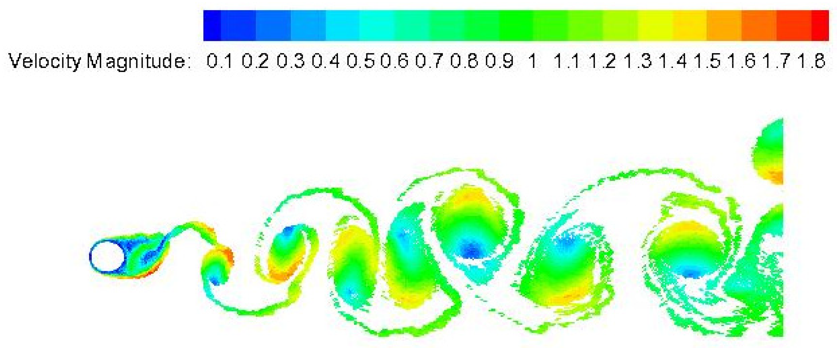
Figure 8 shows the velocity field behavior in the flow simulation at t = 80 for the configuration of the mode of vortex shedding not synchronized with the rough cylinder motion (case V). In this desynchronization regime, the drag force increased over 9% when comparing cases II and V (Table 1).
Figure 8.
Case V: Instantaneous velocity field behind the cylinder for mode A-I (f0 = 0.04) with ε/D = 0.007 at t = 80.
The key contribution of this paper is incorporating the influence of surface roughness on the wake modes behind a streamwisely oscillating cylinder without altering the surface geometry. In this research, the roughness model has a major impact on the A-I mode for oscillation frequency f0 = 0.04, where it can identify alternate, out-of-phase shedding of vortices from either side of the cylinder during an oscillation cycle; the classical Kármán mode is characterized (Table 1). In the past, Bimbato et al. [] applied the present roughness model for a stationary cylinder (classical Kármán vortex) and reported that a roughness height of ε/D = 0.0045 provokes vortical structures narrower than ones in agreement to what is expected from the critical flow regimes. This conclusion was successively supported by the behavior of the boundary layer separation points on the cylinder surface. In the present study, it can be concluded that the combination of roughness effect and forced structural vibration is also more sensitive for the A-I mode, in which the desynchronization regime (f0/fCD = 0.957) has started. The roughness height of ε/D = 0.0070 confirms the occurrence of a desynchronization regime (f0/fCD = 0.789) with increased drag force.
4.3. Circular Cylinder with Forced Vibration: Mode A-IV
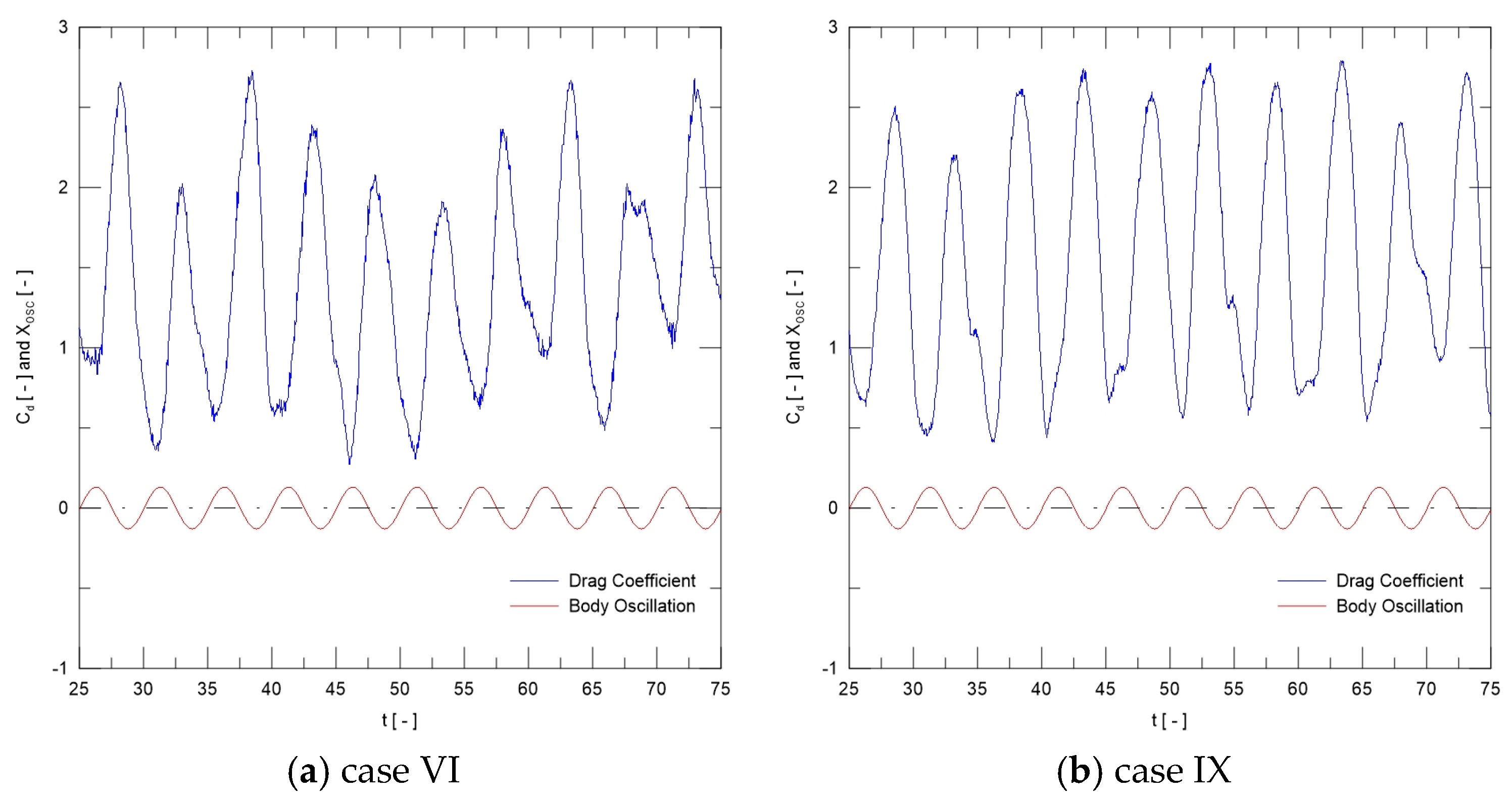
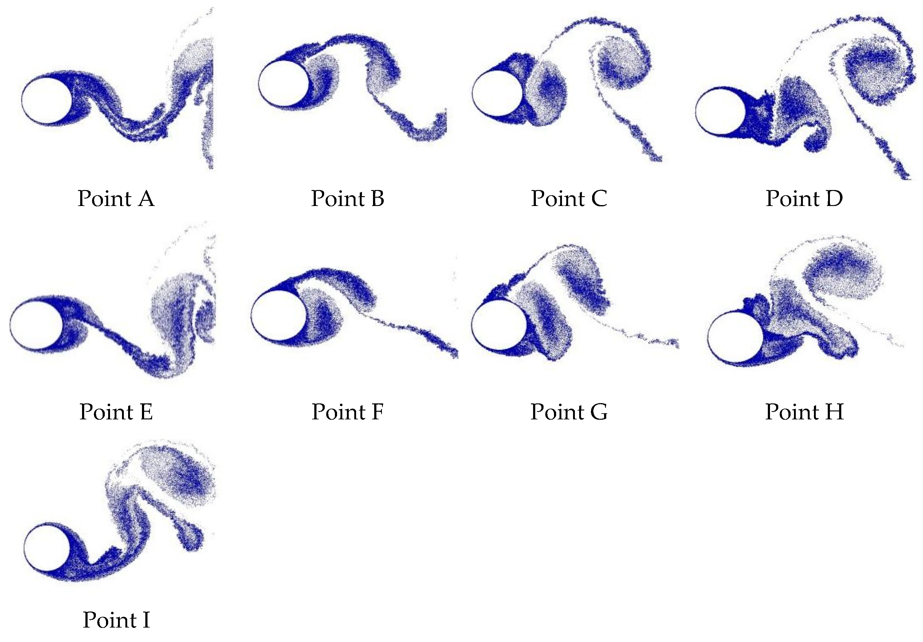
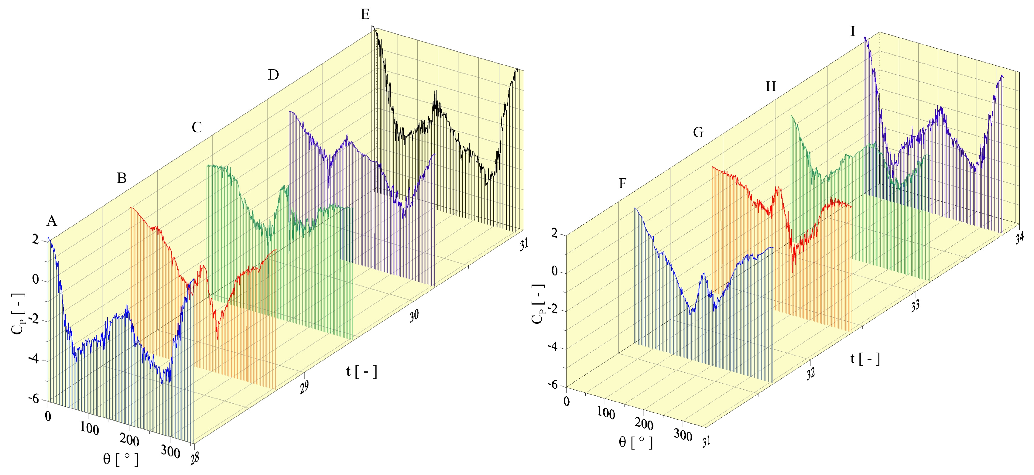
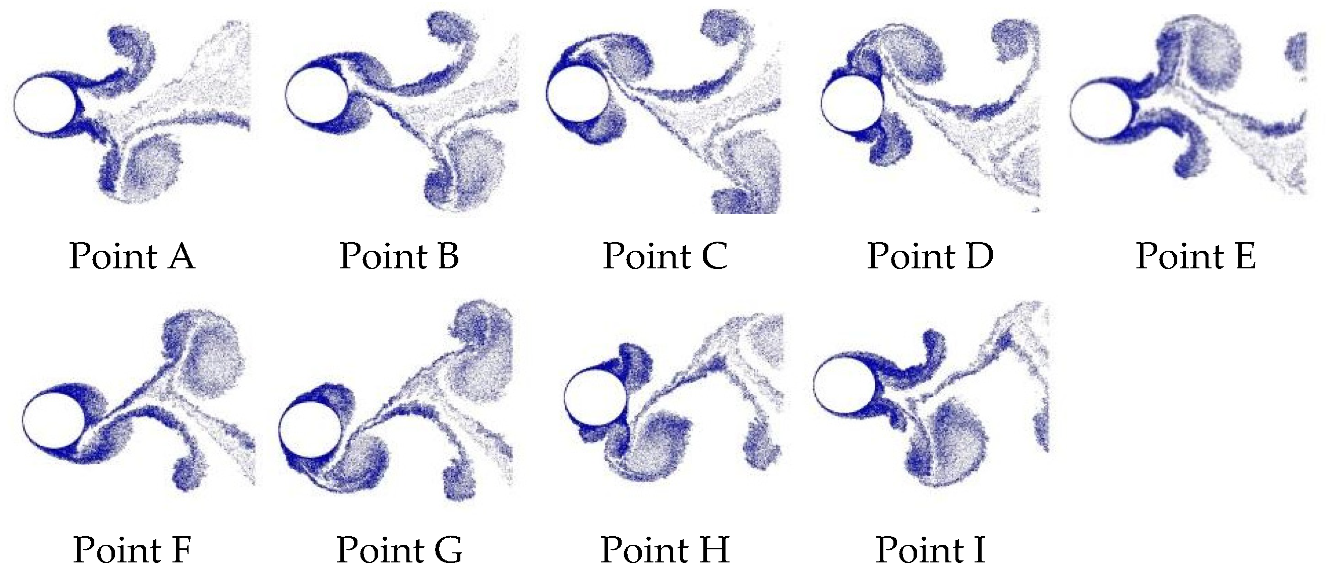
In Figure 2, the time instants identified by points A, B, C, D, E, F, G, H, and I indicate that anti-symmetric A-IV mode requires two cycles of cylinder motion. During the first cycle, the cylinder moves from A to E, and a pair of counter-rotating vortices is shed from the cylinder surface; in the second cycle, when the cylinder is moving from E to I, another pair of counter-rotating vortices is detached. Additionally, the oscillation frequency imposed over the cylinder to capture the A-IV mode must be f0 = 0.20 (cases VI-IX in Table 1). For the anti-symmetric A-IV mode, the effect of surface roughness (ε/D = 0.001–0.007) did not remove the lock-in regime; however, the drag force increased over 12% when comparing cases VI and IX.
Figure 9 illustrates the time histories of drag coefficient and motion displacement xosc(t). Figure 10 sketches the formation of the A-IV mode during two oscillation cycles of the rough cylinder in the lock-in regime (f0/fCD = 1.0).
Figure 9.
Time variation of drag coefficients and motion displacement xosc(t) for mode A-IV (f0 = 0.20): (a) ε/D = 0.000 and (b) ε/D = 0.007.
Figure 10.
Mode A-IV: Distribution of discrete point vortices constructing the near wake pattern for the flow past oscillating cylinder (f0 = 0.20, g/D = 1000, ε/D = 0.007, and Re = 1.0 × 10⁵).
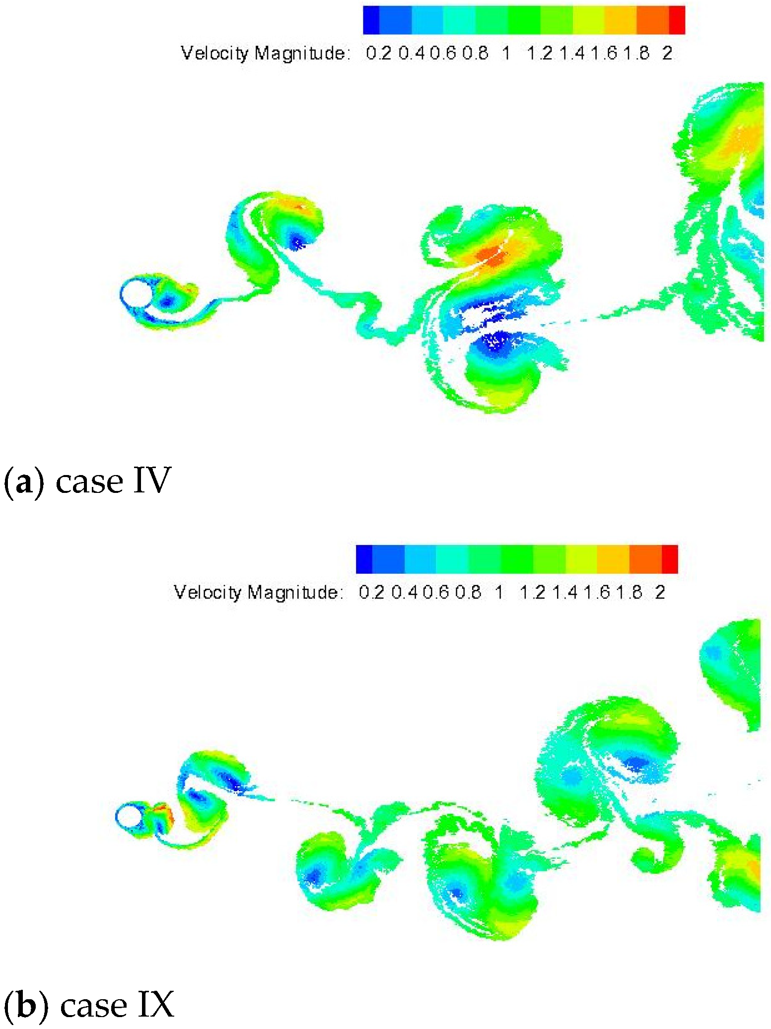
Figure 11 shows the velocity field in the flow simulation at t = 75 for the A-IV mode with and without surface roughness effect.
Figure 11.
Instantaneous velocity field behind the cylinder for mode A-IV (f0 = 0.20) at t = 75: (a) ε/D = 0.000 and (b) ε/D = 0.007.
4.4. Circular Cylinder with Forced Vibration: Modes S-I (Type-I) and A-IV with Coalescence
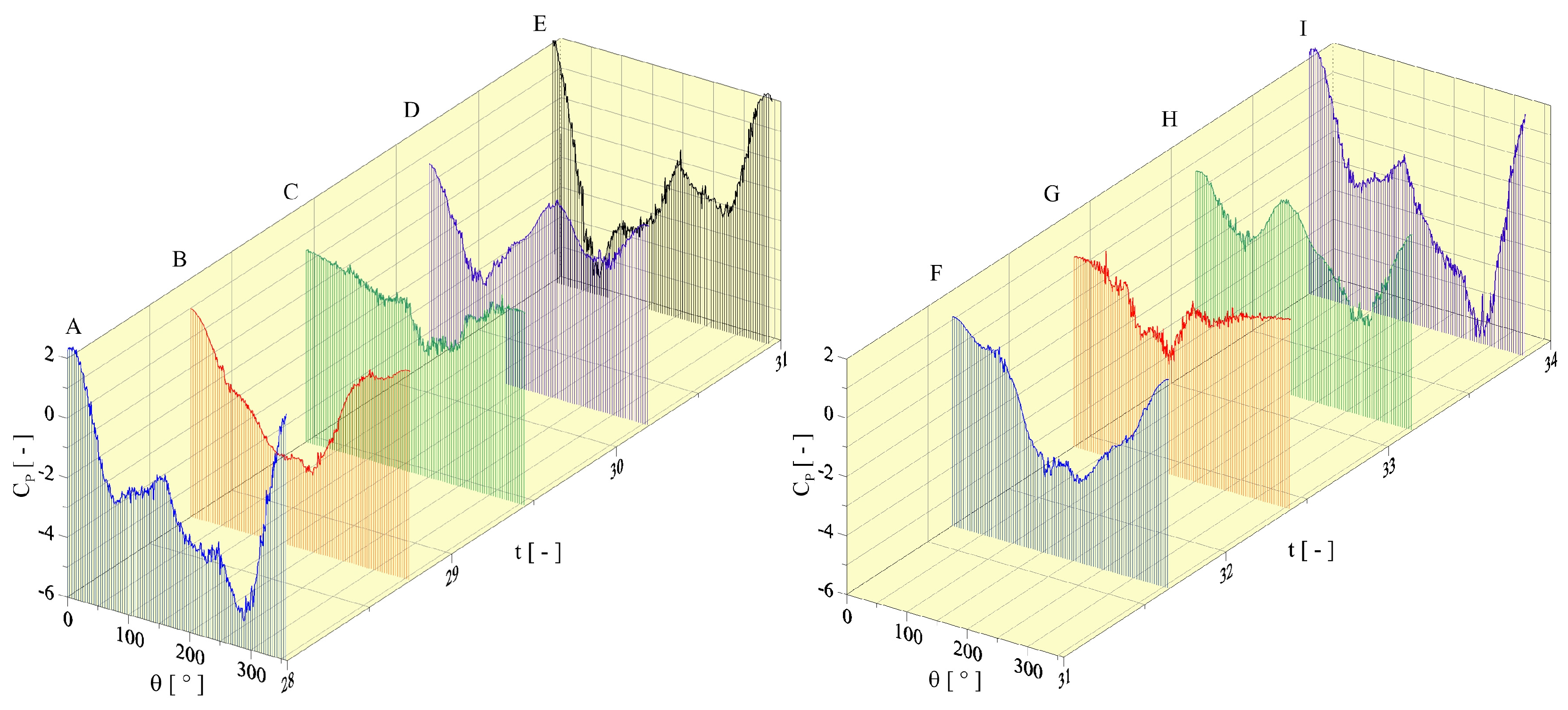
As described by Hu et al. [], mode S-I (Type-I) can be identified when twin vortices are shed in phase from the cylinder surface during one oscillation cycle. These twin vortices immediately coalesce in the near wake region. In Figure 12 (case X in Table 1), the instantaneous pressure distributions reveal an approximately symmetric loading from both sides of the smooth cylinder. During one oscillation cycle (points A–E), one pair of twin vortices detaches from cylinder surface; see also points A–E in Figure 13.
Figure 12.
Instantaneous pressure distributions for mode S-I (Type A-I) (f0 = 0.34 and ε/D = 0.000).
Figure 13.
Mode S-I (Type-I): Distribution of discrete point vortices constructing the near wake pattern for the flow past oscillating cylinder (f0 = 0.34, ε/D = 0.000, g/D = 1000, and Re = 1.0 × 10⁵).
In Figure 12, the time instants marked by points E–I confirm that new twin vortices are detached during the next oscillation cycle; see also points E–I in Figure 13.
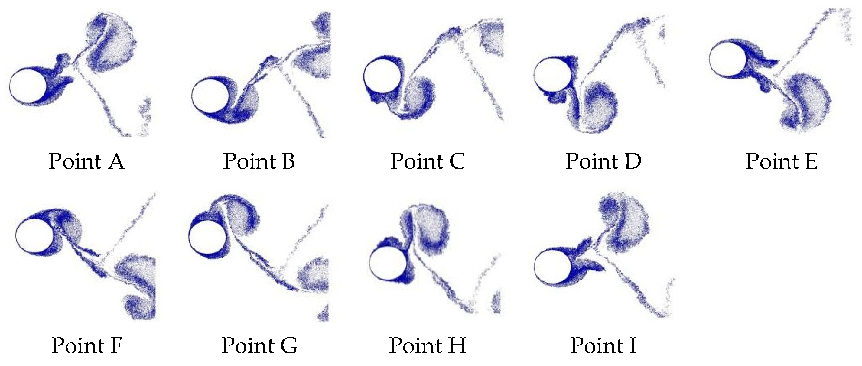
The new wake mode, numerically captured via the mesh-free two-dimensional discrete vortex method coupled with a roughness model (ε/D = 0.007), can be identified in Figure 14 and Figure 15. This vortex formation regime is classified as “mode A-IV with coalescence” (case XIII in Table 1), and it also requires two cycles of cylinder motion. During the first oscillation cycle, the cylinder moves from A to E, and it is possible to identify a pair of counter-rotating vortices detaching from the cylinder surface (see points A–E in Figure 14 and Figure 15). When the cylinder moves from E to I, the second oscillation cycle is completed, and detaching of a pair of counter-rotating vortices is clearly identified in Figure 14 and Figure 15 through interpretation of the time instants marked by points E–I. The variation in relative roughness sizes (ε/D = 0.001–0.007) did not remove the lock-in regime, since f0/fCD = 1 in Table 1. However, the wake mode switched from mode S-I (Type-I) to mode A-IV with coalescence. In this change in mode synchronization, the drag force increased over 25% when comparing cases X and XIII (Table 1).
Figure 14.
Instantaneous pressure distributions for mode A-IV with coalescence (f0 = 0.34 and ε/D = 0.007).
Figure 15.
Mode A-IV with coalescence: Distribution of discrete point vortices constructing the near wake pattern for the flow past an oscillating cylinder (f0 = 0.34, ε/D = 0.007, g/D = 1000, and Re = 1.0 × 10⁵).
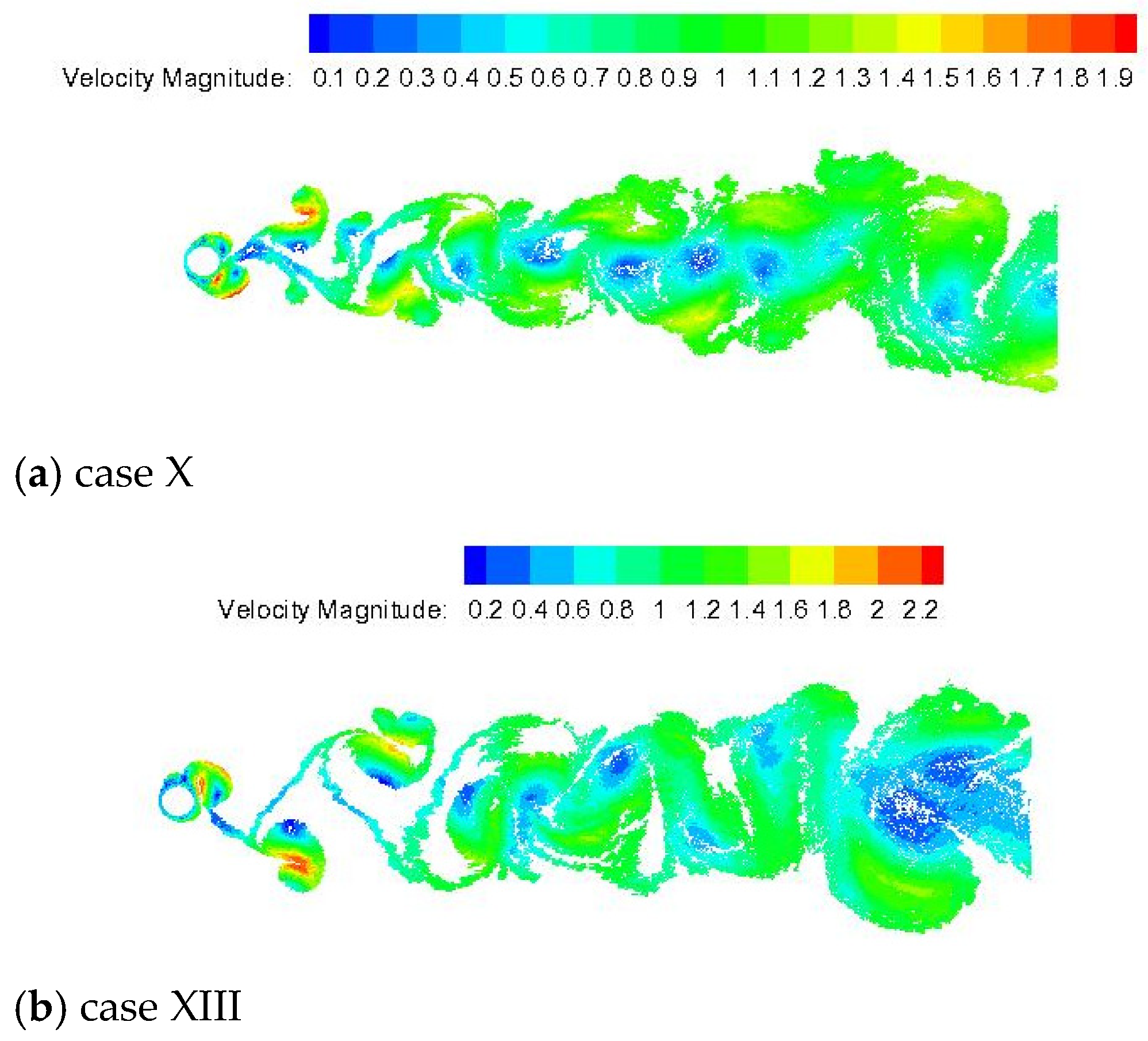
Figure 16a illustrates the wake mode classified as mode S-I (Type-I) supported by instantaneous velocity field distribution for a Reynolds number of Re = 1.0 × 10⁵ at t = 50. It can be clearly observed that twin vortices are detached from the cylinder surface with no roughness effect (case X) and coalesce in the near wake region, as experimentally reported by Hu et al. [] for Re = 360–460 using the laser-induced fluorescence flow visualization technique.
Figure 16.
Instantaneous velocity field behind the cylinder with f0 = 0.34 at t = 50: (a) mode S-I (Type-I) for ε/D = 0.000) and (b) mode A-IV with coalescence for ε/D = 0.007.
The roughness effect was more sensitive for ε/D = 0.007, where the formation of mode A-IV with coalescence can be identified in Figure 16b (Case XIII). The anti-symmetric A-IV mode appeared from the cylinder surface and remained in the near wake region before the vortices coalesced downstream of the rough cylinder.
Therefore, the present research has revealed a clear and abrupt switch in the near wake region, when S-I (Type-I) mode switches to A-IV mode with coalescence because of the roughness effect. The mesh-free two-dimensional discrete vortex method coupled with a source panel method was able to capture the wake modes behind a cylinder in streamwisely oscillating motion, agreeing well with the physics of the problem.
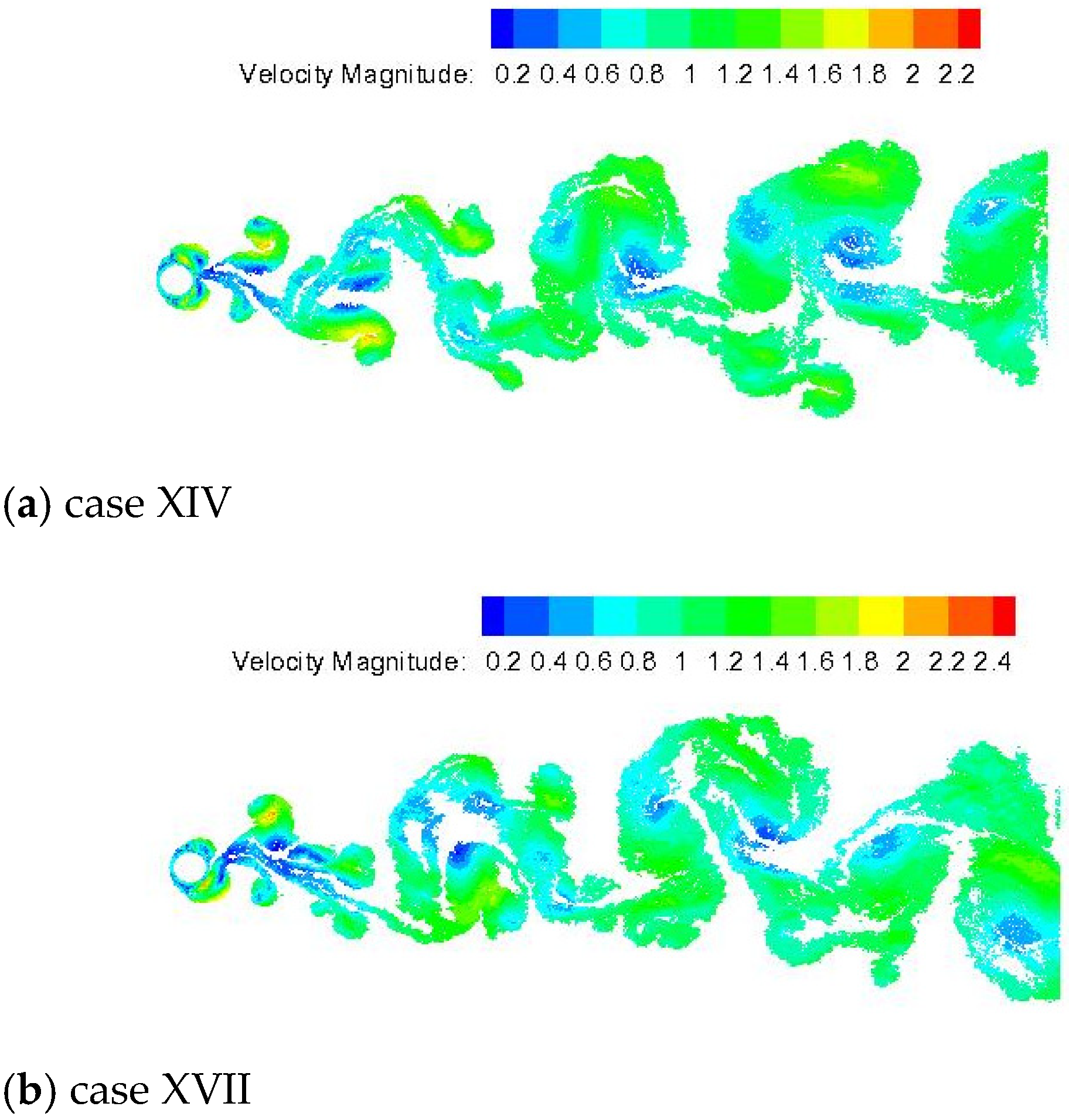
Interestingly, when the forcing frequency varies from f0 = 0.34 to 0.40, the variation in the relative roughness sizes (ε/D = 0.001–0.007) did not provoke mode A-IV with coalescence; however, the lock-in regime remained as mode S-I (Type-I) since f0/fCD = 1 in Table 1 (cases XIV–XVII). Figure 17 illustrates the velocity field in the flow simulation at t = 50 for the configurations with and without roughness effect, respectively, cases XIV and XVII. In this synchronization regime, the drag force increased over 3% when comparing cases XIV and XVII (Table 1).
Figure 17.
Instantaneous velocity field behind the cylinder for mode S-I (Type-I) with f0 = 0.40 at t = 50: (a) ε/D = 0.000 and (b) ε/D = 0.007.
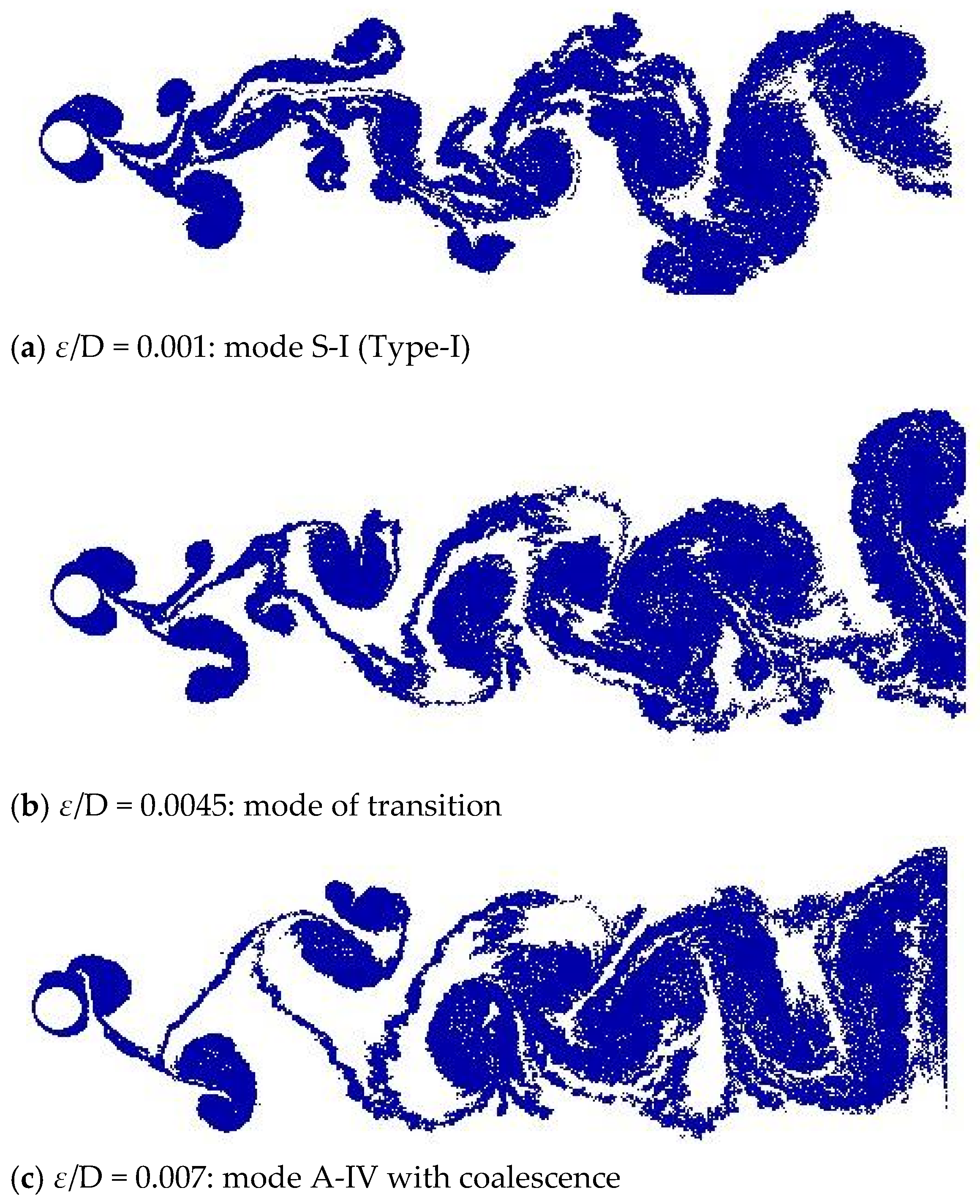
In Table 1, the case identified as XII indicates an interesting transition from mode S-I (Type-I) to mode A-IV with coalescence. That transition is provoked by increasing the relative roughness size from ε/D = 0.001 to 0.007, being that the configuration with ε/D = 0.0045 was classified as “mode of transition”. Figure 18 illustrates the position of the discrete point vortices present in the flow simulation at t = 50 and the classification of the modes identified by simulations.
Figure 18.
Position of the wake vortices at t = 50 (f0 = 0.34, g/D = 1000, and Re = 1.0 × 10⁵): in 18b it is identified transition from mode S-I (Type-I), 18a, to mode A-IV with coalescence, 18c.
4.5. Circular Cylinder with Forced Vibration: Mode C-I
Ongoren and Rockwell [] reported that a cylinder undergoing controlled oscillations at angle δ = 0° with respect to the freestream velocity also presents strong competition between symmetric and anti-symmetric modes over the frequency approximately ranging from f0/f = 0.5 to 1.0. In other words, the mode competition is categorized when synchronization does not occur and there is competition between the symmetric and anti-symmetric modes. Additionally, the near-wake structure successively locks-in to every mode over a defined number of cycles and suddenly switches between modes. In this research, the competition regime is not captured for f0/fCD = 1.0 when adopting the cylinder forcing frequency f0 = 0.80.
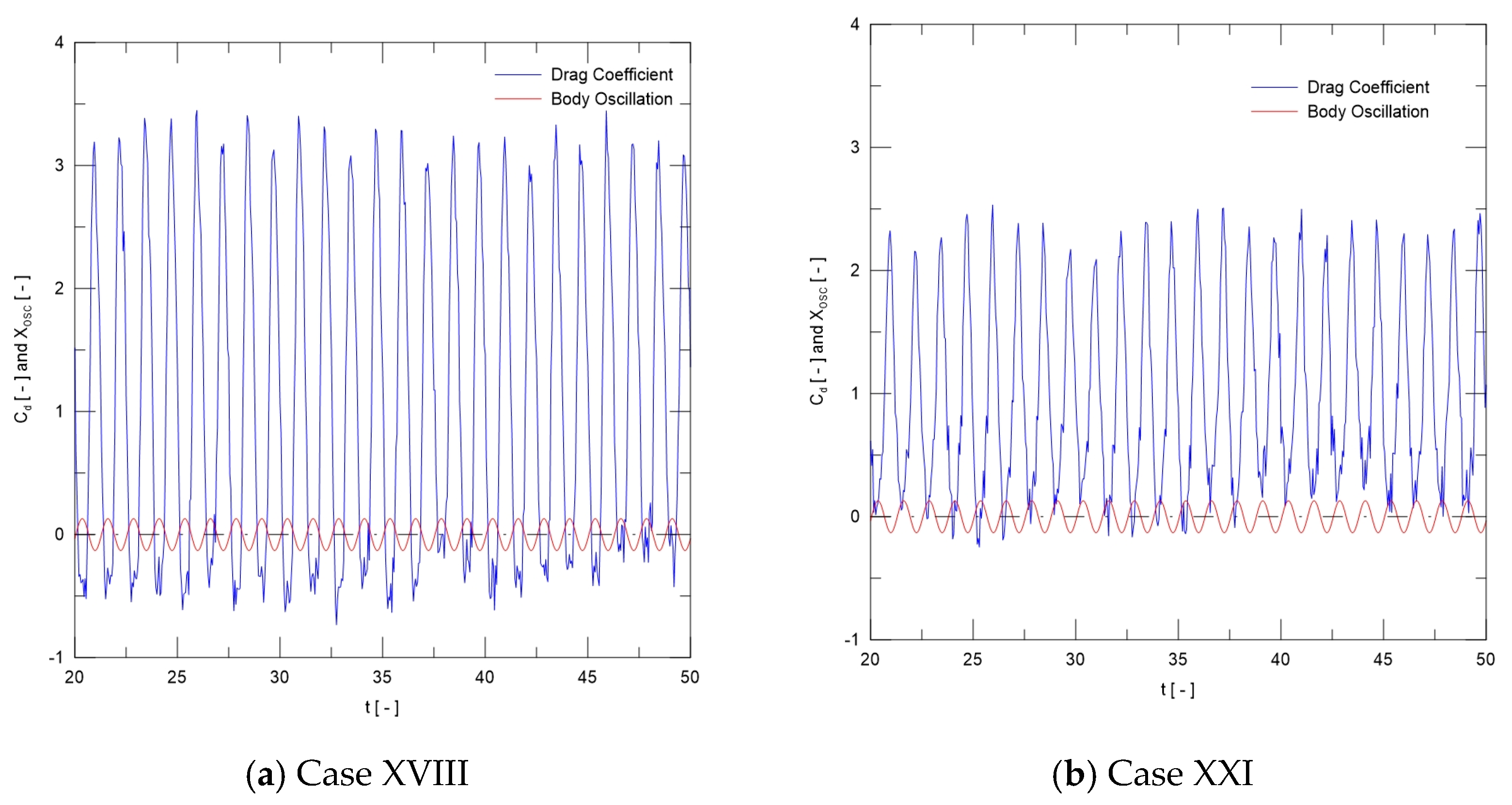
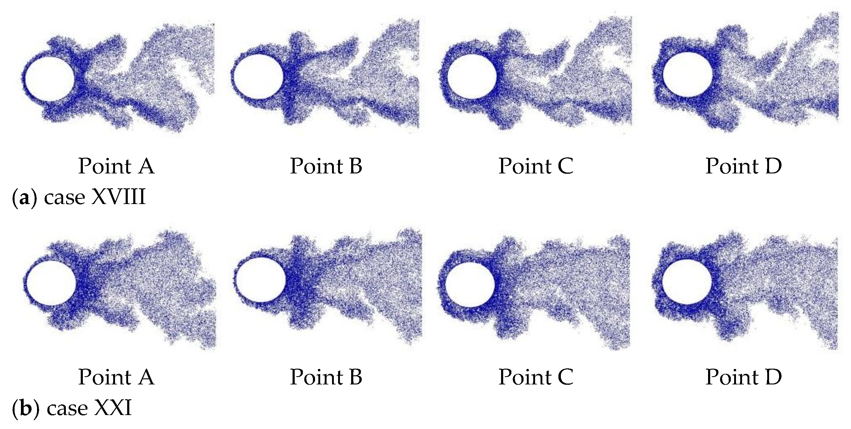
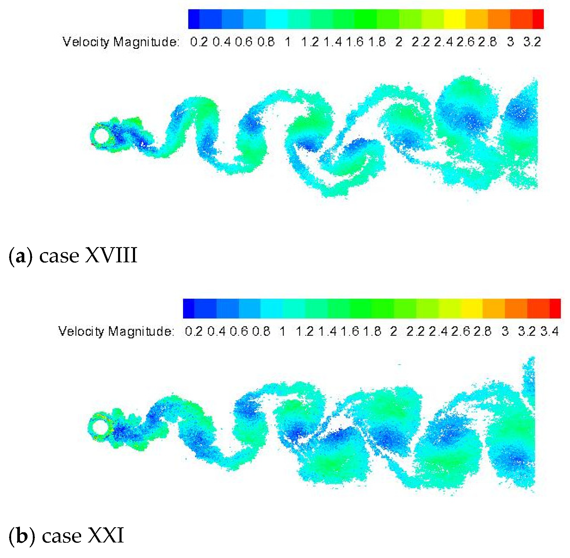
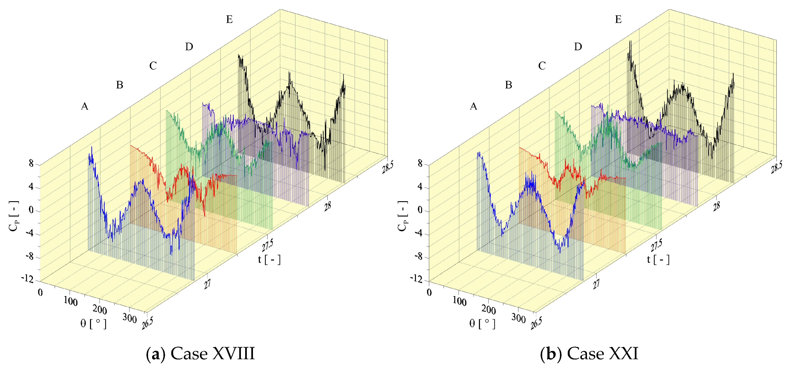
On the other hand, the frequency f0 = 0.80 provokes the Chaotic mode experimentally captured by Hu et al. [] and classified as the C-I mode. Figure 19 shows the time histories of drag coefficient and motion displacement xosc(t) corresponding to cases XVIII and XXI in Table 1. Figure 20 presents the instantaneous pressure distributions, in which an initially synchronized symmetric mode is clearly identified from the cylinder surface and travels into the near wake region (Figure 21).
Figure 19.
Time variation in drag coefficient and motion displacement xosc(t) for mode C-I with f0 = 0.80: (a) ε/D = 0.000 and (b) ε/D = 0.007.
Figure 20.
Instantaneous pressure distributions for mode C-I with f0 = 0.80: (a) ε/D = 0.000 and (b) ε/D = 0.007.
Figure 21.
Mode C-I: Distribution of discrete point vortices constructing the near wake pattern for the flow past an oscillating cylinder for f0 = 0.80, g/D = 1000, and Re = 1.0 × 10⁵: (a) ε/D = 0.000 and (b) ε/D = 0.007.
The variation in the relative roughness size from ε/D = 0.001 to 0.007 did not provoke desynchronization since f0/fCD = 1 in Table 1. This behavior is confirmed by analyzing the near wake pattern reproduced in Figure 21.
Figure 22 shows that the symmetric mode synchronizes in the near wake and coalesces to construct vortices of larger scale into the viscous wake, which really characterizes the C-I mode. The drag force decreased over 9% when comparing cases XVIII and XXI (Table 1).
Figure 22.
Instantaneous velocity field behind the cylinder for mode C-I with f0 = 0.80 at t = 50: (a) ε/D = 0.000 and (b) ε/D = 0.007.
The present simulation shows that the cylinder forcing frequency f0 = 0.80 seems sufficiently high, making impossible a gradual decay from the symmetric to anti-symmetric mode in the near wake region (Figure 21 and Figure 22). The frequency f0 = 0.60 provokes the same wake mode identified for f0 = 0.80, although the results have been omitted in this paper.
5. Conclusions
The present study numerically investigates the effect of surface roughness on the VIV characteristics of a circular cylinder under streamwisely forcing oscillating motion at constant angle δ = 0° with respect to the freestream velocity. The numerical approach is based on a mesh-free two-dimensional discrete vortex method coupled with a source panel method. All simulations considered a high Reynolds number of Re = 1.0 × 10⁵, which is based on the cylinder diameter, D. A series of calculations was carried out a fixed dimensionless oscillation amplitude (A/D = 0.13) and a wide range of cylinder forcing frequency (i.e., 0.04 ≤ fo ≤ 0.80) to systematically investigate changes in wake modes because of the relative roughness sizes, namely ε/D = 0.001, 0.0045, and 0.007. The conclusions can be summarized as follows (see Table 1):
- (1)
- The numerical results obtained with no roughness effect are in overall good agreement with the experimental visualizations from Ongoren and Rockwell [] by adopting A/D = 0.13, δ = 0°, and Re = 855. Preliminary studies concluded that the amplitude A/D = 0.13 was sufficiently large to control the near wake pattern over a wide frequency range []. However, only the symmetric S-I (Type-I) mode, the anti-symmetric A-I and A-IV modes, and mode C-I are numerically captured at a high Reynolds number flow of Re = 1.0 × 10⁵ over frequency ratio f0/fCD = 1.0. The Chaotic mode C-I was also experimentally visualized by Hu et al. [].
- (2)
- The lock-in modes appear in the following order: A-I for f0 = 0.04 ⟶ A-IV for f0 = 0.20 ⟶ S-I (Type-I) for f0 = 0.34 and 0.40 ⟶ C-I for f0 = 0.80.
- (3)
- The relative roughness size of ε/D = 0.007 desynchronizes the anti-symmetric A-I mode at f0 = 0.04. The drag force increases over 9% when comparing case II (ε/D = 0.000) and case V (ε/D = 0.007).
- (4)
- The variation in relative roughness size does not desynchronize the anti-symmetric A-IV mode at f0 = 0.20. However, the drag force increases over 12% when comparing case VI (ε/D = 0.000) and case IX (ε/D = 0.007).
- (5)
- The variation in relative roughness size abruptly switches from S-I (Type-I) mode (ε/D = 0.000) to “mode A-IV with coalescence” (ε/D = 0.007) at f0 = 0.34. The test case XII (ε/D = 0.0045) is here importantly classified as the “transition mode”. The drag force also increases over 25% when comparing case X (ε/D = 0.000) and case XIII (ε/D = 0.007).
- (6)
- The variation in relative roughness size does not desynchronize the S-I (Type-I) mode at f0 = 0.40. The drag force slightly increases over 3% when comparing case XIV (ε/D = 0.000) and case XVII (ε/D = 0.007).
- (7)
- The test cases at f0 = 0.80 demonstrate that the near wake structure successively locks-in to symmetric mode. This cylinder forcing frequency seems sufficiently high to not produce decay to an anti-symmetric mode. The vortices quickly coalesce to vortices of larger scales, as shown in Figure 21 and Figure 22. Interestingly, the drag force decreases over 9% when comparing case XVIII (ε/D = 0.000) and case XXI (ε/D = 0.007).
As the simulations show, the numerical results obtained are in overall good agreement with the experimental data used for comparison (see Table 1 and Section 4.1).
The use of parallel computing (OpenMP) to determine vortex-induced velocities allows for an increase in the number of discrete point vortices and a reduction in the time stepping. The computer used to run the simulations had the following specifications: CPU Intel Core i9-13900KF 3.00 GHz with 32 threads, and L2 cache of 32 MB. Every test case needed approximately 120 h of wall clock time to complete. Therefore, as future improvements, the CUDA technology will be implemented in our algorithm []. The use of CUDA will increase the resolution of the simulations, reduce the CPU time, and provide the means for longer-time simulations to be carried out.
Finally, the present methodology will be extended to include ground effect mechanisms [] and mixed convection heat transfer [].
Author Contributions
Conceptualization, T.R.C., G.F.M.d.C. and L.A.A.P.; data curation, T.R.C., G.F.M.d.C. and A.M.B.; formal analysis, T.R.C., G.F.M.d.C. and L.A.A.P.; funding acquisition, L.A.A.P. and A.M.B.; investigation, T.R.C., G.F.M.d.C. and A.M.B.; methodology, P.G.d.M., A.M.B. and L.A.A.P.; project administration, T.R.C. and L.A.A.P.; resources, T.R.C., G.F.M.d.C. and L.A.A.P.; software using Fortran, T.R.C., G.F.M.d.C., V.H.G.F. and P.G.d.M.; validation, T.R.C., G.F.M.d.C. and A.M.B.; visualization, T.R.C., G.F.M.d.C., V.H.G.F. and P.G.d.M.; supervision, L.A.A.P.; writing—original draft, T.R.C. and L.A.A.P.; writing—review and editing, G.F.M.d.C., P.G.d.M. and L.A.A.P. All authors have read and agreed to the published version of the manuscript.
Funding
This research was funded by the FAPEMIG (a research-supporting foundation of Minas Gerais), project no. APQ-01246-23; the São Paulo Research Foundation (FAPESP), grant no. 2022/03630-4; and the National Council for Scientific and Technological Development (CNPq), grant 404539/2023-8. The authors thank the Coordination for the Improvement of Higher Education Personnel (CAPES, Finance Code 001) for granting master’s scholarships to the first author.
Institutional Review Board Statement
Not applicable.
Informed Consent Statement
Not applicable.
Data Availability Statement
The raw data supporting the conclusions of this article will be made available by the authors upon request.
Conflicts of Interest
The authors declare no conflicts of interest.
Abbreviations
The following abbreviations are used in this manuscript:
| CPU | Central Processing Unit |
| CUDA | Compute Unified Device Architecture |
| FFT | Fast Fourier Transform |
| FIV | Flow-Induced Vibration |
| FSI | Flow–Structure Interaction |
| LES | Large-Eddy Simulation |
| LVM | Lagrangian Vortex Methods |
| RWM | Random Walk Method |
| VIV | Vortex-Induced Vibration |
References
- Mimeau, C.; Mortazavi, I. A Review of Vortex Methods and Their Applications: From Creation to Recent Advances. Fluids 2021, 6, 68. [Google Scholar] [CrossRef]
- Ricciardi, T.R.; Wolf, W.R.; Bimbato, A.M. Fast multipole method applied to Lagrangian simulations of vortical flows. Commun. Nonlinear Sci. Numer. Simul. 2017, 51, 180–197. [Google Scholar] [CrossRef]
- Salloum, S.; Lakkis, I. An Adaptive Error-Controlled Hybrid Fast Solver for Regularized Vortex Methods. J. Comput. Phys. 2022, 468, 111504. [Google Scholar] [CrossRef]
- Marchevsky, I.; Ryatina, E.; Kolganova, A. Fast Barnes-Hut-Based Algorithm in 2D Vortex Method of Computational Hydrodynamics. Comput. Fluids 2023, 266, 106018. [Google Scholar] [CrossRef]
- Xiong, S.; He, X.; Tong, Y.; Deng, Y.; Zhu, B. Neural Vortex Method: From Finite Lagrangian Particles to Infinite Dimensional Eulerian Dynamics. Comput. Fluids 2023, 258, 105811. [Google Scholar] [CrossRef]
- Chorin, A.J. Numerical Study of Slightly Viscous Flow. J. Fluid. Mech. 1973, 57, 785–796. [Google Scholar] [CrossRef]
- Leonard, A. Vortex methods for flow simulation. J. Comput. Phys. 1980, 37, 289–335. [Google Scholar] [CrossRef]
- Lewis, R.I. Vortex Element Methods, The Most Natural Approach to Flow Simulation—A Review of Methodology with Applications. In Proceedings of the 1st International Conference on Vortex Methods, Kobe, Japan, 4–5 November 1999; pp. 1–15. [Google Scholar]
- Alcântara Pereira, L.A.; Hirata, M.H.; Silveira Neto, A. Vortex Method with Turbulence Sub-grid Scale Modeling. J. Braz. Soc. Mech. Sci. Eng. 2003, 25, 140–146. [Google Scholar] [CrossRef]
- Kamemoto, K. On contribution of advanced vortex element methods toward virtual reality of unsteady vortical flows in the new generation of CFD. J. Braz. Soc. Mech. Sci. Eng. 2004, 26, 368–378. [Google Scholar] [CrossRef]
- Bimbato, A.M.; Alcântara Pereira, L.A.; Hirata, M.H. Study of Surface Roughness Effect on a Bluff Body—The Formation of Asymmetric Separation Bubbles. Energies 2020, 13, 6094. [Google Scholar] [CrossRef]
- Oliveira, M.A.; Moraes, P.G.; Andrade, C.L.; Bimbato, A.M.; Alcântara Pereira, L.A. Control and Suppression of Vortex Shedding from a Slightly Rough Circular Cylinder by a Discrete Vortex Method. Energies 2020, 13, 4481. [Google Scholar] [CrossRef]
- Narsipur, S.; Ramesh, K.; Gopalarathnam, A.; Edwars, J.R. Discrete vortex modeling of perching and hovering maneuvers. Theor. Comput. Fluid Dyn. 2023, 37, 445–464. [Google Scholar] [CrossRef]
- Zou, Q.; Zhou, C.; Zhu, C.; Zhang, Z.; Fan, J. Discrete Vortex Method-Based Fish-Like Locomotion Modeling. IEEE J. Ocean. Eng. 2024, 49, 390–402. [Google Scholar] [CrossRef]
- Rahul, K.; Padhee, S.S.; Samanta, D. Aerodynamic performance and flow mechanism of 3D flapping wing using discrete vortex method. J. Fluids Struct. 2024, 127, 104128. [Google Scholar] [CrossRef]
- Hirata, M.H.; Alcântara Pereira, L.A.; Recicar, J.N.; Moura, W.H. High Reynolds Number Oscillations of a Circular Cylinder. J. Braz. Soc. Mech. Sci. Eng. 2008, 30, 368. [Google Scholar] [CrossRef]
- Wang, Y.B.; Zhao, H.C.; Gao, D.L.; Li, R. Numerical simulation of vortex-induced vibration of deepwater drilling riser based on discrete vortex method. Pet. Sci. 2025, 22, 2042–2061. [Google Scholar] [CrossRef]
- Chiaradia, T.R.; Carvalho, G.F.M.d.; Bimbato, A.M.; Alcântara Pereira, L.A. A Contribution to the Temperature Particles Method—Implementation of a Large-Eddy Simulation (LES) Model for the Temperature Field. Appl. Sci. 2025, 15, 4122. [Google Scholar] [CrossRef]
- Zhao, M. A review of recent studies on the control of vortex-induced vibration of circular cylinders. Ocean Eng. 2023, 285, 115389. [Google Scholar] [CrossRef]
- Bearman, P.W. Understanding and Predicting Vortex-Induced Vibrations. J. Fluid Mech. 2009, 634, 1–4. [Google Scholar] [CrossRef]
- Ongoren, A.; Rockwell, D. Flow structure from an oscillating cylinder Part 2. Mode competition in the near wake. J. Fluid. Mech. 1988, 191, 225–245. [Google Scholar]
- Hu, Z.; Liu, J.; Gan, L.; Xu, S. Wake modes behind a streamwisely oscillating cylinder at constant and ramping frequencies. J. Vis. 2019, 22, 505–527. [Google Scholar] [CrossRef]
- Xu, S.; Zhou, Y.; Wang, M. A symmetric binary-vortex street behind a longitudinally oscillating cylinder. J. Fluid Mech. 2006, 556, 27–43. [Google Scholar] [CrossRef]
- Katz, J.; Plotkin, A. Low Speed Aerodynamics: From Wing Theory to Panel Methods; McGraw Hill Inc.: Columbus, OH, USA, 1991. [Google Scholar]
- Kamemoto, K. On Attractive Features of the Vortex Methods, Computational Fluid Dynamics Review; Hafez, M., Oshima, K., Eds.; John Wiley & Sons: Hoboken, NJ, USA, 1995; pp. 334–353. [Google Scholar]
- Shintani, M.; Akamatsu, T. Investigation of two-dimensional discrete vortex method with viscous diffusion model. CFD J. 1994, 3, 237–254. [Google Scholar] [CrossRef]
- Ferziger, J.H. Numerical Methods for Engineering Application; John Wiley & Sons, Inc.: Hoboken, NJ, USA, 1981. [Google Scholar]
- Helmholtz, H. On integrals of the hydrodynamics equations which express vortex motion. Philos. Mag. 1867, 33, 485–512. [Google Scholar] [CrossRef]
- Lesieur, M.; Métais, O. New Trends in Large Eddy Simulation of Turbulence. Rev. Fluid Mech. 1996, 28, 45–82. [Google Scholar] [CrossRef]
- Carvalho, G.F.M.d.; Vidille, M.F.; Bimbato, A.M.; Alcântara Pereira, L.A. Lagrangian Vortices Interactions Using Large-Eddy Simulation (LES) and Surface Roughness Model—Application for Aircraft Wake Vortices with Crosswind. Appl. Sci. 2023, 13, 12336. [Google Scholar] [CrossRef]
- Blevins, R.D. Applied Fluid Dynamics Handbook; Van Nostrand Reinhold Co.: Hoboken, NJ, USA, 1984. [Google Scholar]
- Moraes, P.G.d.; Oliveira, M.A.d.; Bimbato, A.M.; Pereira, L.A.A. A Lagrangian Description of Buoyancy Effects on Aircraft Wake Vortices from Wing Tips near a Heated Ground Plane. Energies 2022, 15, 6995. [Google Scholar] [CrossRef]
Disclaimer/Publisher’s Note: The statements, opinions and data contained in all publications are solely those of the individual author(s) and contributor(s) and not of MDPI and/or the editor(s). MDPI and/or the editor(s) disclaim responsibility for any injury to people or property resulting from any ideas, methods, instructions or products referred to in the content. |
© 2025 by the authors. Licensee MDPI, Basel, Switzerland. This article is an open access article distributed under the terms and conditions of the Creative Commons Attribution (CC BY) license (https://creativecommons.org/licenses/by/4.0/).