1. Introduction
The investigation of shock wave and detonation phenomena is of considerable interest due to their potential applications in the development of next-generation propulsion systems [
1]. Computational fluid dynamics (CFD) is particularly valuable for identifying the steady operating range of rotating detonation engines. In a continuous detonation engine, combustion occurs within an annular chamber where a detonation wave propagates tangentially. This wave consumes the incoming fuel–oxidizer mixture as it travels around the annulus. The self-sustained propagation of the detonation front arises from the interaction between unsteady flow structures behind the leading shock front and the shock itself [
2]. Because of the complex interaction between the detonation wave and the chamber walls, various propagation modes may develop, including unstable behavior characterized by detonation failure or re-initiation [
3]. The onset of re-initiation is primarily influenced by the geometry of the channel and the initial pressure conditions [
4].
For a detonation wave to propagate steadily, the fuel mixture condition in front of the traveling front must remain constant or fluctuate only slightly enough to not affect the wave speed and structure [
5]. Diffraction on the outer and inner cylinder surfaces occurs in conjunction with the tangential propagation of a detonation wave in an annular channel with finite curvature. The maximum pressure on the outer wall of a cylindrical combustion chamber is 20–25% higher than inner wall due to the diffraction of the detonation wave. This results in the formation of transverse shock wave structures that interact with the transverse waves of the detonation front. Areas of decreased pressure are found where transverse waves of different structures collide, which causes an early supply of fuel components to explosion products. Ref. [
5] states that the detonation front has a W-shaped shape, with leading points in the gap’s center and on the inner and outer walls. A cellular detonation structure is formed as a result of a plane wave disruption. The diffraction and generation of spinning three-dimensional detonation waves in an annular gap between parallel plates is examined in [
6].
The detonation combustion front is a complex shock wave structure with at least two triple configurations, according to studies on continuous circular detonation [
7,
8]. The detonation front moves over the annular gap with the least amount of detonation combustion feasible thanks to the cooperation of the triple configurations and the detonation combustion zone. The studies reported provide insight into the complex dynamics of detonation wave propagation in annular channels and the various factors that can influence their stability [
9,
10].
Shock wave propagation in a curved channel is characterized by complex processes, including reflections, scattering and re-radiation of energy, which lead to a change in the amplitude and shape of the wave, as well as the emergence of secondary shock waves, reflections and vortex structures. Analysis of these phenomena requires the use of computer modeling and complex numerical methods that take into account the channel geometry, the properties of the medium and the characteristics of the initial shock wave. Shock waves are an irreversible process that leads to losses of kinetic energy of the flow and an increase in its entropy, which reduces the overall efficiency.
Flow in a curved channel with a square cross-section (diffraction of shock waves in two-dimensional channels with a 90 degrees bend) is studied in [
11,
12,
13] based on physical and numerical data. Measurements and calculations are carried out for two channel configurations with different radius of curvature and different Mach numbers. A wide range of challenges related to the unsteady interaction of shock waves is discussed in [
14]. The possibilities and limits of applicability of geometrical shock dynamics in relation to the description of shock wave diffraction are considered in [
15,
16]. The mechanisms of shock wave diffraction on convex and concave isolated surfaces are discussed in many studies. Despite the achieved results and level of understanding of shock wave structures, shock wave diffraction and organization of shock waves and detonation processes in detonation engines is still the topic of theoretical, experimental, and numerical research [
17,
18,
19,
20,
21,
22,
23,
24,
25].
Curvature, turns and variable cross-section of the channel cause wave reflection from the walls. Density, viscosity and temperature of the medium affect the velocity and attenuation of the shock wave [
26,
27]. The initial amplitude, duration and spectral composition of the wave determine its further behavior. The shock wave is repeatedly reflected from the walls, with part of the energy lost due to scattering and conversion to heat. In complex sections of the channel, the wave front can become inhomogeneous and non-perpendicular to the walls. In channels with sharp turns, vortex structures arise that can influence the further propagation of the wave [
28]. The physical mechanisms associated with the evolution of the shock profile is evaluated in [
28] for shock waves with initial profiles comprising a cylindrical arc, placed in-between two straight segments, propagating in a converging channel.
This study investigates the diffraction of shock waves in a curved channel. Numerical simulations are performed for various channel curvature radii and initial Mach numbers. The evolution of the shock wave structure within the curved channel, as well as the characteristic dimensions and position of the Mach stem as functions of time and inlet conditions, are analyzed. The numerical results are compared with experimental data, demonstrating good qualitative agreement. The findings provide insights that may contribute to developing effective combustion organization strategies for rotating detonation engines.
It is worth noting that the problem of shock propagation through curved channels, such as U- or S-shaped channels, tube bends, and coils, is closely related to the shock-to-detonation transition phenomenon studied in detonation engines. While the present study focuses on inert flow dynamics in annular channels, the flow patterns observed here differ from those in continuous detonation engines not only due to chemical transformations but also due to differences in the inflow and outflow schemes. Mentioning this connection helps to situate the current work within the broader context of shock-driven flows and related research on detonation initiation.
2. Mathematical Model and Numerical Method
An inviscid (Euler) flow model is employed to describe the high-speed flow. This choice is justified based on the dominant physical mechanisms and the objectives of the analysis. At high Mach numbers, the flow behavior is primarily governed by compressibility effects, shock-wave interactions, and large pressure gradients, rather than by viscous diffusion. In such cases, the viscous regions (such as boundary layers and shear layers) are typically thin compared to the overall flow domain, and their influence on the main flow field or shock structure is relatively minor. Consequently, neglecting viscosity provides an accurate representation of the core flow and shock phenomena, while significantly reducing computational cost and complexity. Moreover, simulations focus on capturing inviscid aerodynamic features (e.g., shock location, pressure distribution, and wave interaction), for which the Euler equations are sufficient. Inclusion of viscous or turbulence models would mainly affect local boundary-layer behavior and heat transfer, which are beyond the present scope.
The inviscid assumption is, therefore, appropriate and widely accepted in the literature for high-speed external flows when the interest lies in the overall flowfield and shock structure rather than detailed viscous effects.
To simulate unsteady two-dimensional compressible inviscid fluid flows, the conservation form of the Euler equations written in a Cartesian frame of reference
is used. The governing equations are written as
The total energy per unit volume for a perfect gas is determined from the following equation:
The vector of conservative flow variables and the corresponding flux vectors are given by
Here,
t is time,
is the density,
u and
v are the velocity components in the Cartesian directions
x and
y,
p is the static pressure,
e is the total energy per unit volume, and
is the ratio of specific heat capacities at constant pressure and constant volume.
The steady-state Euler equations can be solved using a variety of explicit and implicit time-marching techniques based on high-order TVD or ENO finite-difference schemes (
1). Additionally, unstable flows with severe discontinuities governed by the Euler equations have been effectively simulated using these techniques [
29].
An unstructured internal finite volume CFD algorithm [
30] is used for numerical computations. The algorithm uses an edge-based data structure, which gives it flexibility to work with meshes made up of different kinds of cells. The flow variables at the nodes at each end of an edge and the area connected to that edge (edge weight) are used to calculate fluxes. The geometry of the associated cells is taken into consideration when precalculating the edge weights. Using a three-step Runge–Kutta scheme in conjunction with the piecewise parabolic approach, the non-linear CFD solver proceeds in an explicit time-marching way. The Chakravarthy–Osher scheme is used to evaluate inviscid fluxes. Multigrid approaches and block-Jacobi preconditioning for high-speed flows, along with a distinct low-Mach number preconditioning method for low-speed flows, accelerate convergence. The edge-collapsing algorithm is used to generate the mesh sequence.
Preconditioning is a numerical technique applied to modify the compressible Euler equations to improve convergence and accuracy. High-speed and low-speed flows require different preconditioning treatments because the numerical conditioning of the compressible flow equations strongly depends on the Mach number.
At low Mach numbers, the eigenvalues of the Euler equations (which include the convective and acoustic wave speeds) become highly disparate (the acoustic waves propagate much faster than the convective waves). This results in a stiff and ill-conditioned system, causing slow convergence and loss of accuracy. To alleviate this, low-Mach-number preconditioning is applied to rescale the acoustic wave speeds, improving the balance among characteristic speeds and restoring proper pressure–velocity coupling.
In contrast, at high Mach numbers, the flow is dominated by compressibility effects and strong shock waves, where the natural propagation of acoustic waves must be accurately captured. Applying low-Mach preconditioning in this regime would distort the physical wave behavior and degrade the solution accuracy. Therefore, no preconditioning (or a Mach-number-dependent formulation that deactivates preconditioning as M goes to 1) is used for high-speed flows.
The approach outlined in [
31] was used to control the accumulation of numerical inaccuracies in simulations. The C/C++ programming language is used to implement the computing process. A message passing interface (MPI) and general-purpose graphics processing units (GPUs) are used to parallelize the computational process [
32,
33].
4. Computational Options
A plane shock wave propagates clockwise through air. The calculation results are compared with experimental and calculated data from [
11,
12] on flow structures at various inlet Mach numbers, shock wave propagation speeds, and Mach number distributions on inner and outer walls.
Mach numbers on inner and outer walls of channel are found as
and
, where
is shock wave speed on inner wall and
is shock wave speed on outer wall,
a is speed of sound in an undisturbed flow. Shock wave speeds are found in polar coordinates, taking into account the distance traveled by shock waves along inner and outer walls:
where
and
are angular positions of shock front on inner and outer walls. The angular positions of shock wave front on inner and outer walls are found and maintained at each time moment (
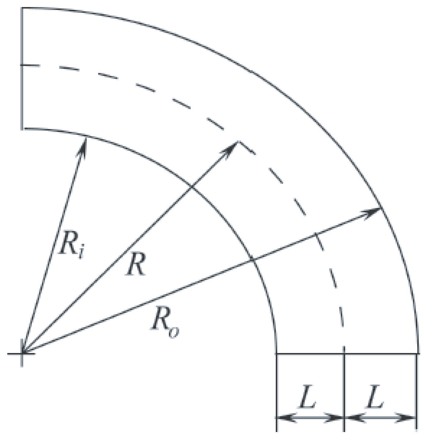
Figure 2). To find the angular position of front at time
t, the magnitude of density derivative with respect to angular coordinate is used,
. For comparison with data of [
11], the calculated values of Mach numbers,
and
, are normalized to the Mach number
. In this case, the distances measured along inner and outer walls are defined as
and
.
In the range
and
, inviscid compressible gas is calculated using proprietary unsteady two-dimensional Euler equations. Discretization of governing equations is performed with finite volume method. Details of discretization and numerical method are given in [
34]. An unstructured mesh containing
triangular cells is generated. Calculations are carried out until the time
ms for case 1 and
ms for case 2 (during this time the shock wave has time to reach outlet channel boundary). An increase in the initial velocity of shock wave leads to a faster exit of the shock wave outside the domain. The Courant number is 0.6.
The minimum size of the cell is 0.0198 mm. Inviscid flow was assumed, and the governing equations were solved in their Euler form. Therefore, no boundary layer development was modeled. The walls were treated as slip boundaries, enforcing zero normal velocity and permitting tangential flow. As viscous effects were neglected, mesh refinement near the wall was dictated solely by geometric and shock-reflection considerations rather than by wall-distance scaling. The smallest cells were concentrated along regions of high curvature and expected shock interaction, with a smooth growth rate below 1.3 in the wall-normal direction to maintain numerical stability and accurate wave reflection. The present inviscid configuration, therefore, achieves sufficient wall resolution to capture geometric focusing and shock diffraction effects without the excessive refinement demanded by viscous modeling.
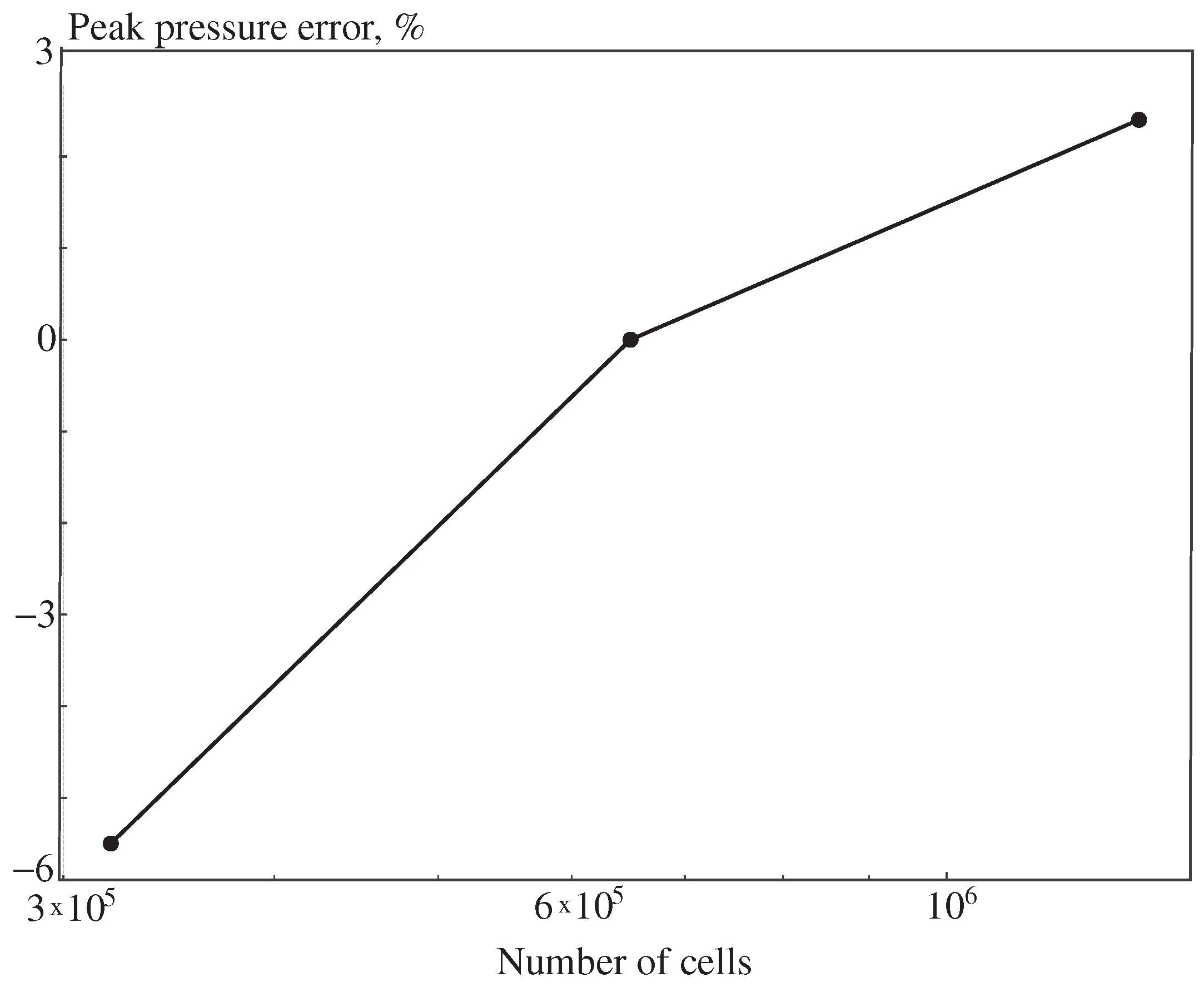
A mesh-independence study was conducted to ensure that the numerical solution was not sensitive to grid resolution (
Figure 3). Three meshes were tested: a coarse grid (
cells), a baseline grid (
cells, used for the main results), and a refined grid (
cells). All other numerical parameters (boundary conditions, solver settings, and time step) were identical. Key integral quantities, including peak overpressure at the inner wall and Mach-stem height, were monitored. Refinement from the baseline to the fine mesh changed the maximum pressure by less than 2.4%, the arrival time by 1.7%, and the Mach-stem height by 2.1%. The coarse grid exhibited slightly higher numerical dissipation and a 5–6% reduction in peak pressure. Based on these results, the mesh with
cells was deemed sufficiently resolved to capture the essential shock-wave structures while maintaining computational efficiency.
5. Results and Discussion
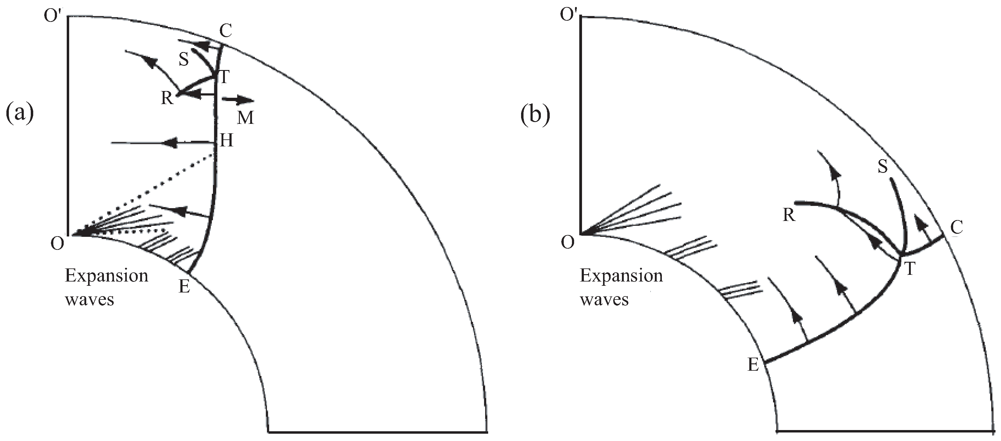
At the initial time, a plane shock wave is formed, which begins to propagate inside the channel. A diagram of shock wave configuration that forms at early stage of flow development is shown in
Figure 4a. The channel curvature leads to difference of shock wave speeds on inner and outer walls. The initially flat shock wave front begins to bend, and shock wave diffracts. The shock wave front is subject to influence of a rarefaction waves fan centered at point O. The angle of inclination of characteristics in rarefaction waves fan depends on Mach number
. As a result of diffraction of shock wave, a triple point T is formed, from which two incident shock waves propagate to the right and to the left the reflected shock wave R and the contact discontinuity S. The contact discontinuity is separated by air flows passing through the Mach wave TC and the incident shock wave ET. The section of the shock wave front between points H and T continues to propagate with a Mach number of
. Non-regular reflection and associated Mach wave TC occur when a shock wave is reflected from a wall. The front of reflected shock wave RT is curved. The contact discontinuity ST is located behind the incident shock wave ET, the intensity of which weakens along the inner wall, while the intensity of Mach wave increases along the outer wall [
35].
The shock wave formed at the inlet and propagating with a Mach number
, exists only at early stage of flow development (
Figure 4a). With the passage of time and flow development, the front of initial shock wave disappears. This occurs due to rarefaction waves that form on inner wall and reach the triple point. Over time, the fan of rarefaction waves moves along inner wall. Due to interaction with rarefaction wave, the intensity of shock wave on lower wall weakens compared to its initial value corresponding to Mach number
. The rarefaction wave fan interacts with that part of shock wave front that propagates with Mach number
and the triple point. This interaction leads to a further increase in curvature of Mach stem. At the same time, the intensity of shock wave on outer wall of channel increases. The diagram of shock wave configuration formed at the late stage of flow development is shown in
Figure 4b. The curvature of Mach wave makes it difficult to use theoretical methods to analyze development of a shock wave configuration in a curved channel.
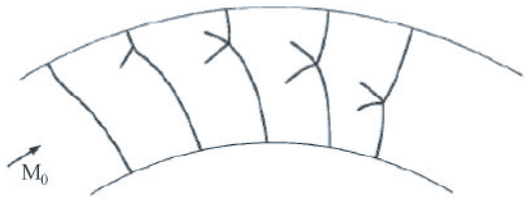
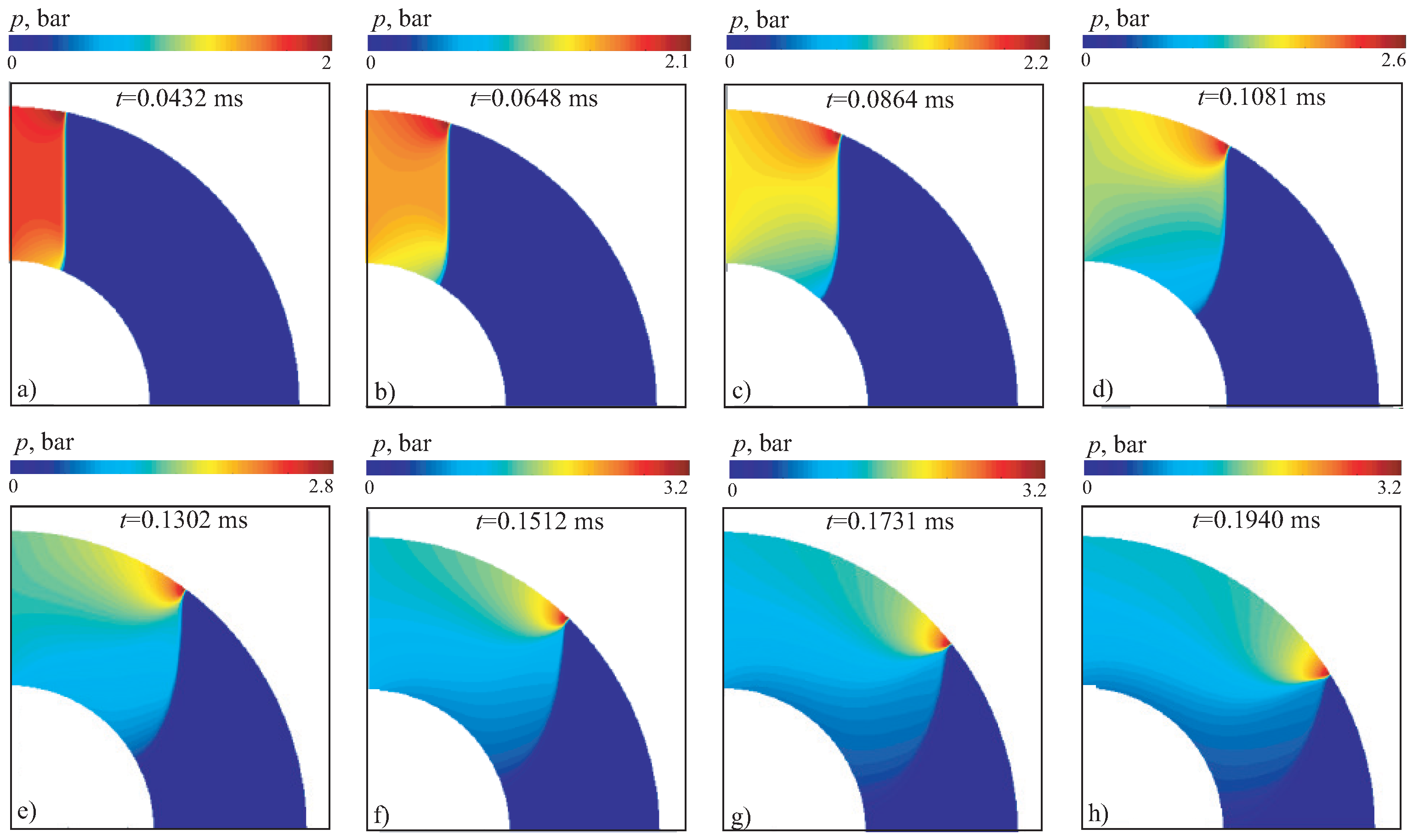
There are certain variances in the curvature of the front of shock waves created in channels of varying radius of curvature. While in case 1 the curvature of shock wave front is preserved during its propagation (
Figure 4), in case 2 a different situation is observed. The triple point moves towards the inner wall faster in case 2 than in case 1 (the speed of movement of triple point depends on initial intensity of shock wave). Rarefaction waves formed on lower wall of channel reach the triple point earlier, and shock wave front again acquires a flat shape (
Figure 5).
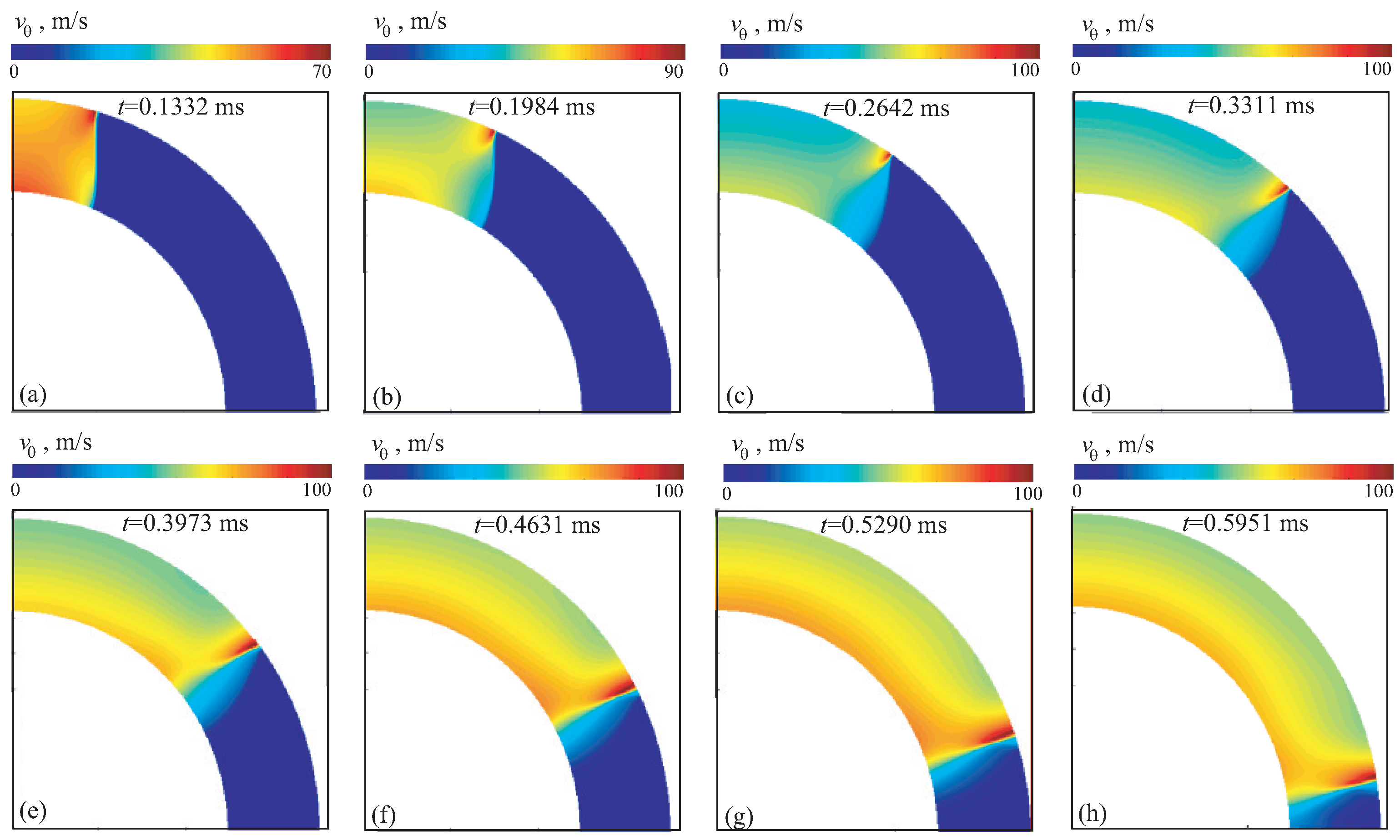
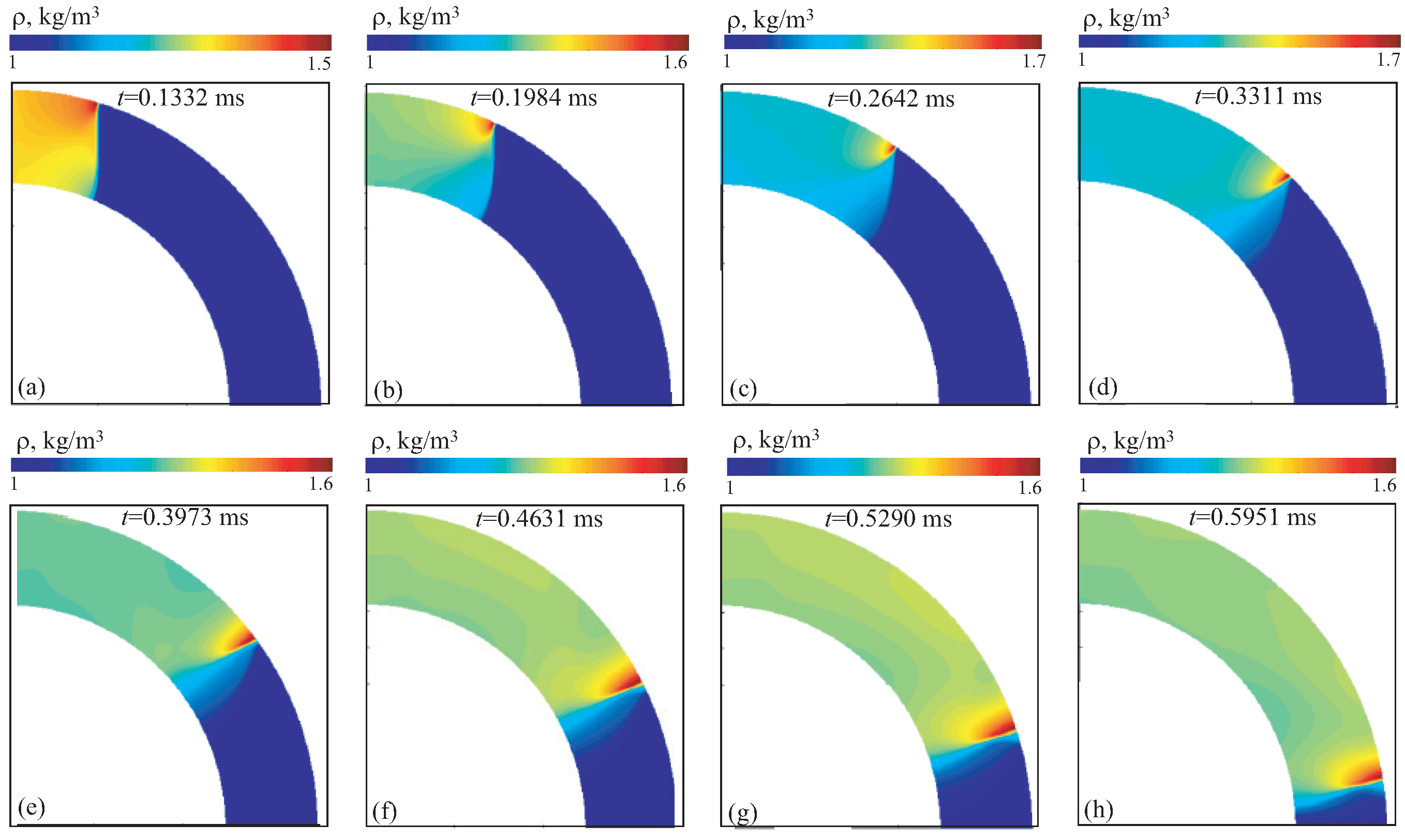
The contours of velocity magnitude, density and pressure for option 1A are shown in
Figure 6 (yellow color shows shock waves reflected from walls),
Figure 7 and
Figure 8 (red color corresponds to areas of flow compression) at different times (option 1A). The results obtained fairly well reproduce the main shock wave structures in the channel, including position of triple point, contact discontinuity, Mach stem. The shape of shock wave front agrees well with that observed in a physical experiment [
11]. The interaction of shock waves with channel walls produces a two-dimensional flow configuration. The size of Mach stem first increases in radial direction to approximately
, and then sharply decreases, leading to regular reflection at angles
and resembles shock diffraction waves on a concave surface (diffraction on convex wall) [
12,
14].
As the Mach number increases, the emergent shock wave flow structures become more apparent, as seen in red
Figure 9,
Figure 10 and
Figure 11 (option 1B). Shock waves reflected from the walls (yellow color in
Figure 6) meet in the middle part of the channel and continue to move towards outlet section of computational domain. Due to interaction of rarefaction waves with triple point, a decrease in intensity of shock wave propagating along inner wall is observed. As the intensity of initial wave increases, an expansion of compressed air region is observed. Both the incident and reflected shock waves maintain their curvature as the change from Mach reflection to regular reflection occurs at
.
Although the nominal Mach numbers differ, the effective flow conditions in the annular geometry produce similar flow behavior. In curved channels, the local flow response depends not only on the incident Mach number but also on the radius of curvature, channel height, and wall confinement ratio.
Stronger curvature (smaller radius) acts to focus the shock toward the inner wall, effectively amplifying local pressures and velocities even if the nominal Mach number is lower. Conversely, a gentler curvature at higher Mach numbers can produce nearly equivalent pressure and wavefront shapes to those in tighter channels with lower Mach numbers. This leads to dynamic similarity between 1B/2B and 1C/2C.
At these Mach numbers, the flow is close to the transition between regular reflection and Mach reflection. The geometry shifts this threshold. A higher Mach number in a larger-radius channel (case C) yields similar reflection patterns to a lower Mach number in a tighter-radius channel (case B), since both conditions produce comparable incident-to-wall angles.
Pressure ratios and flow deflections in compressible flows scale non-linearly with Mach number. Hence, increasing Mach from 2.1 to 2.9 does not double the pressure jump. When geometric focusing or boundary-layer effects offset this, the overall flow structure (wavefront curvature, vortex formation, pressure contour patterns) can appear almost identical.
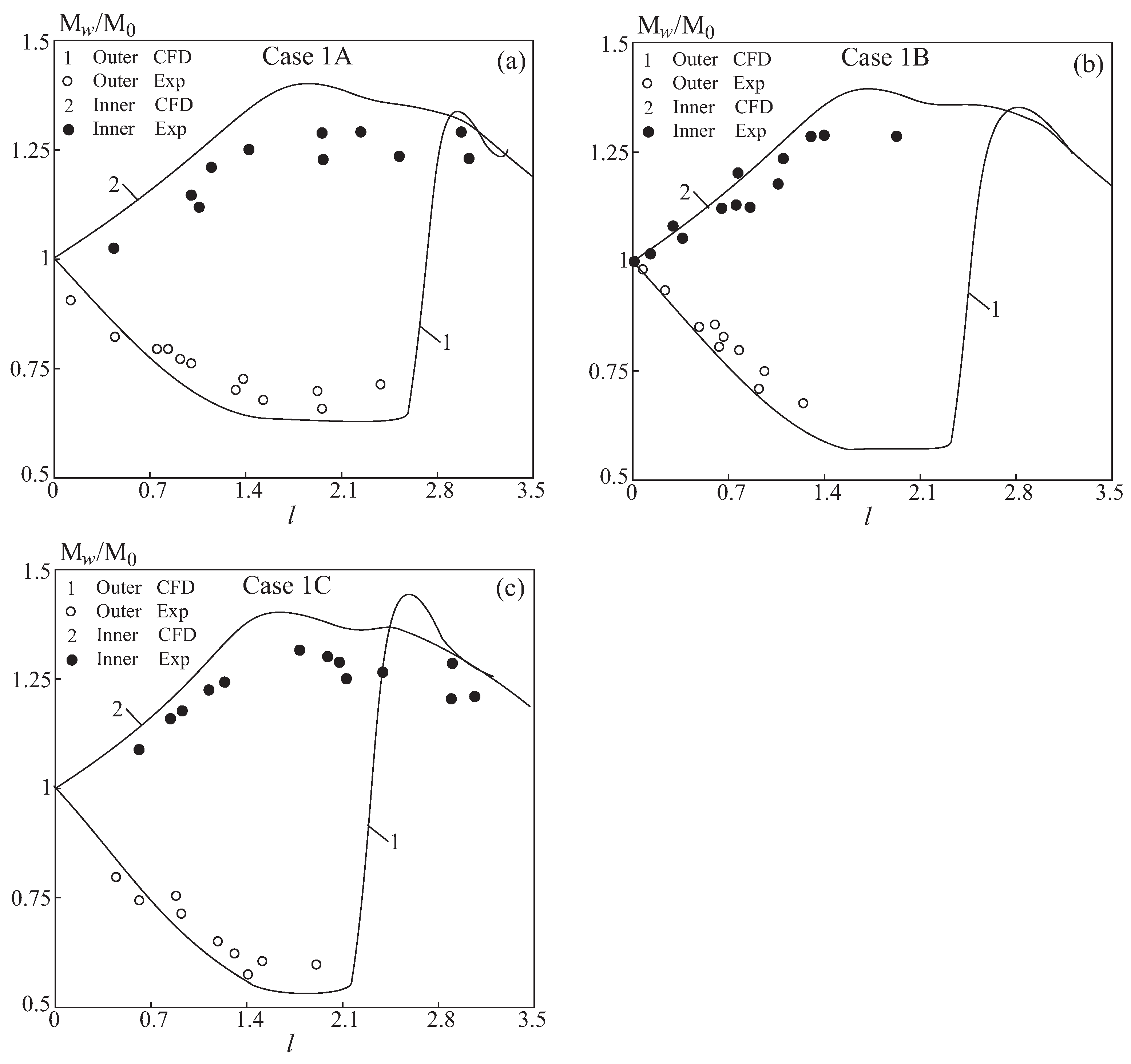
A comparison of the calculated values of Mach numbers on inner and outer walls is shown in
Figure 12. Solid lines correspond to results of CFD simulations, and symbols ○ and ● correspond to experimental data [
11]. The Mach number of shock wave on outer wall increases
, while the Mach number on inner wall decreases
. In this case, there is a better agreement between the results of numerical simulation for outer wall than for inner one. The maximum Mach number on outer wall and the minimum Mach number on inner wall depend rather weakly on speed of initial shock wave, approximately amounting to 1.3 and 0.7, respectively (although there is a slight decrease in the minimum Mach number on lower wall to 0.6 with an increase in initial shock wave speed).
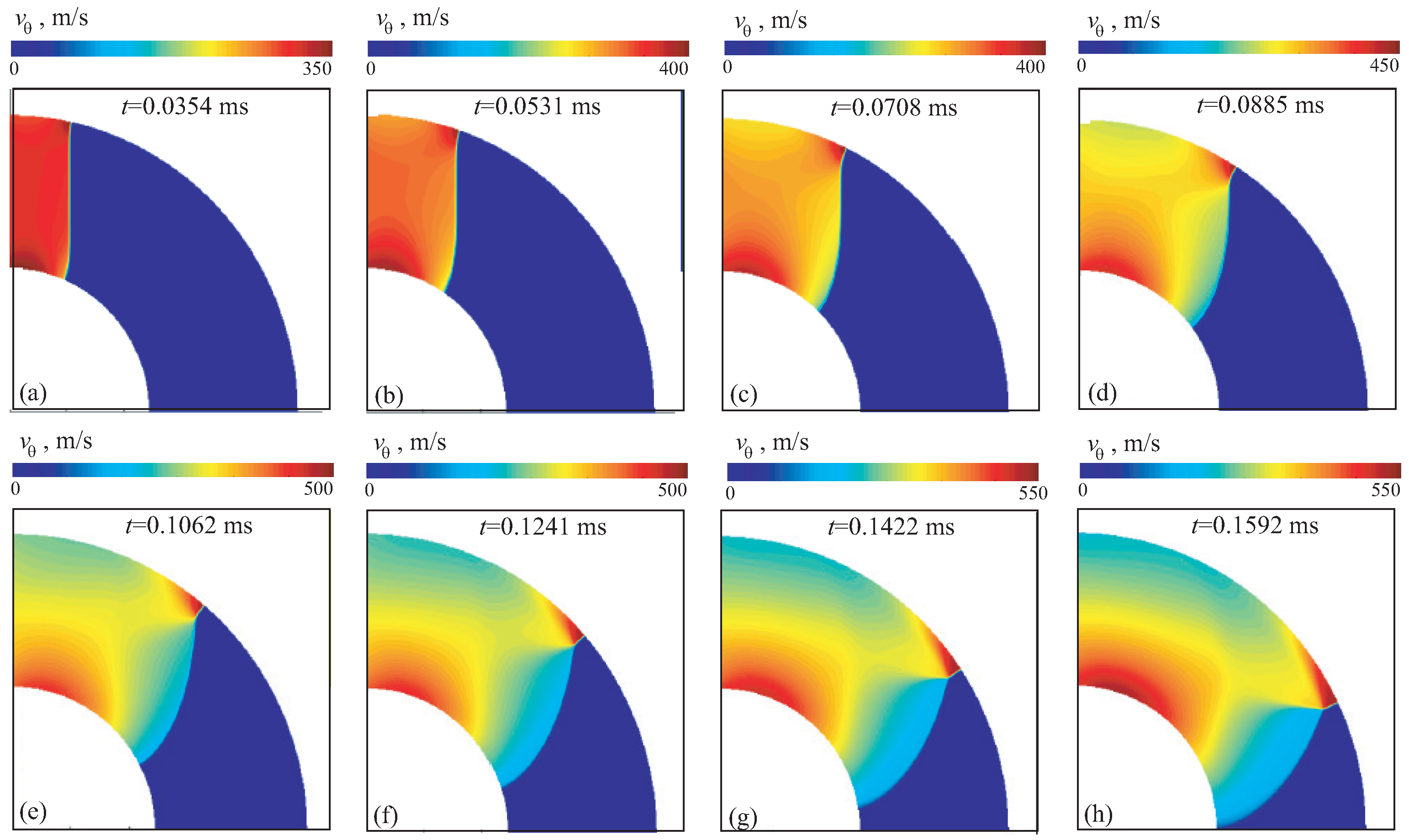
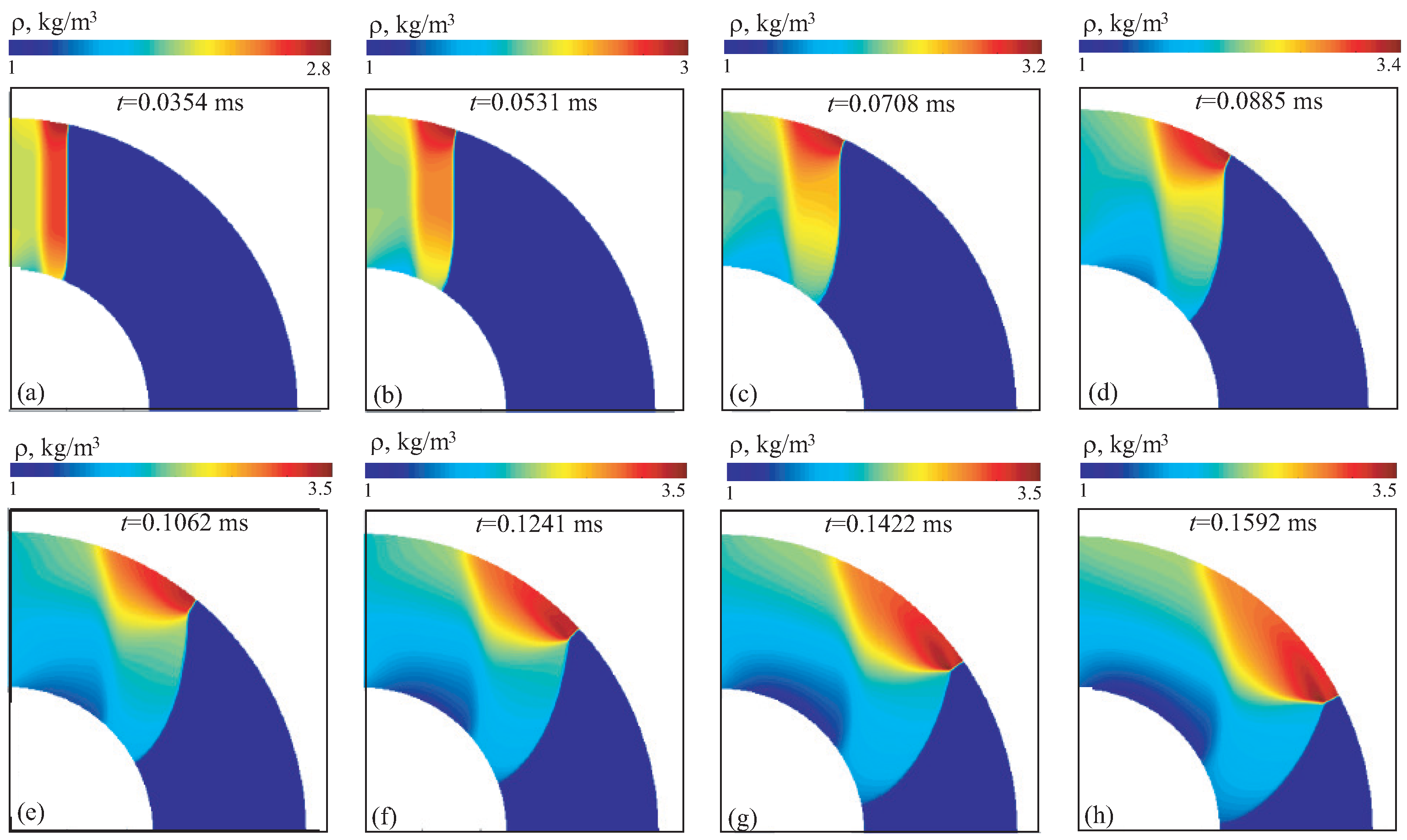
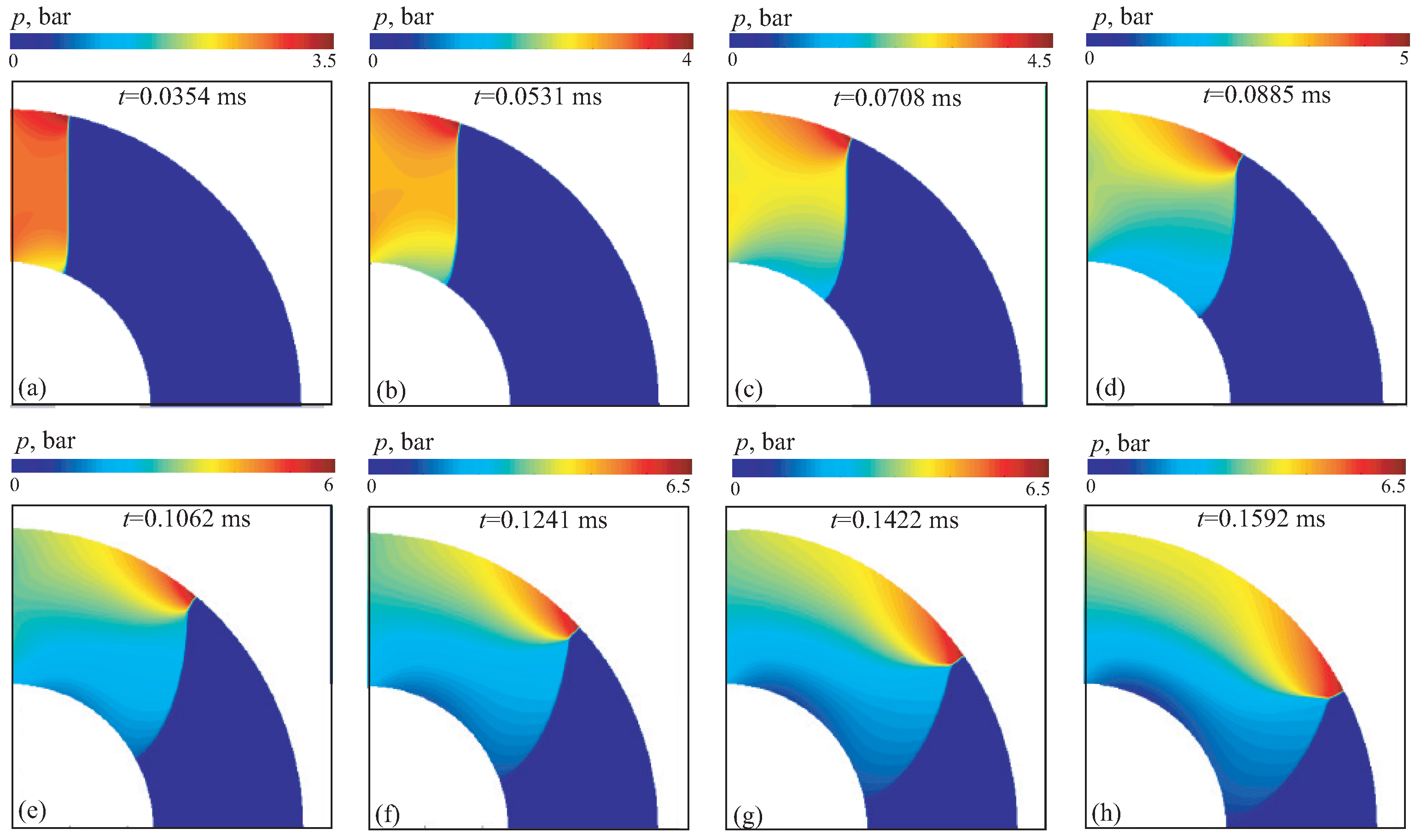
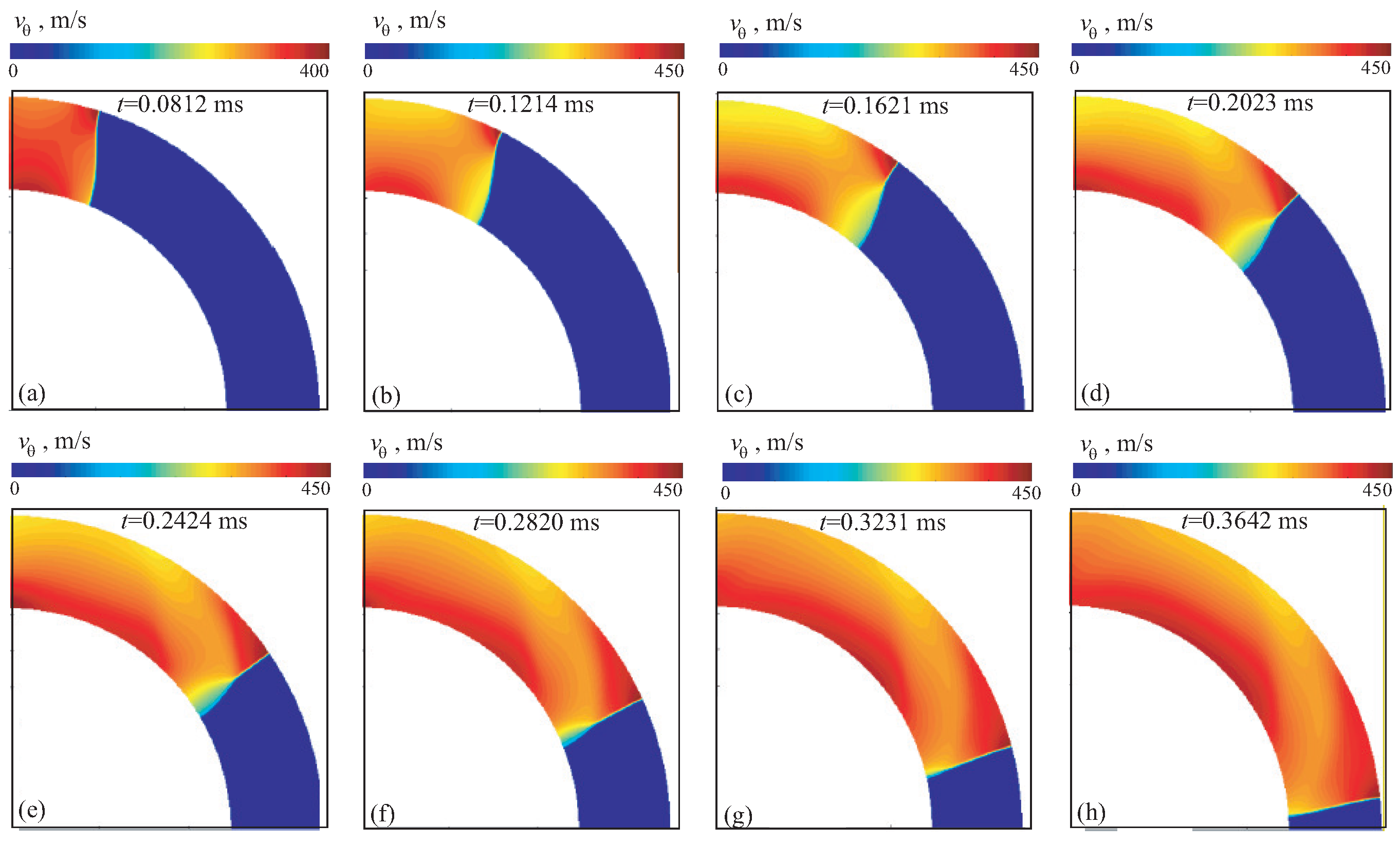
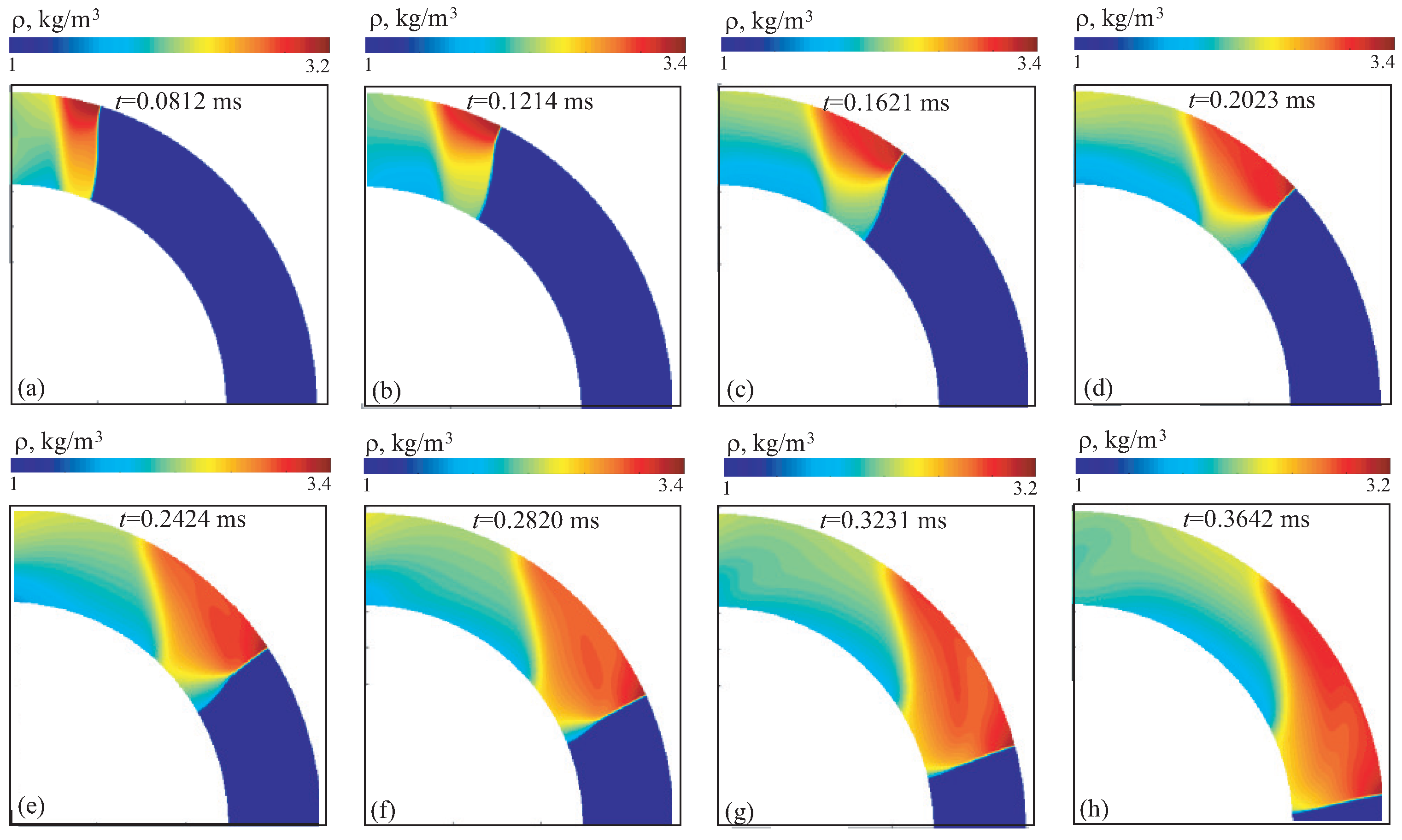
The velocity, density and pressure contours for case 2A are shown in
Figure 13,
Figure 14 and
Figure 15 at different times. In general, the shock wave structure is similar to that observed in case 1. Unlike case 1, the curvature of shock wave front formed at the beginning of channel is not preserved, and its shape turns out to be close to flat due to interaction of rarefaction waves with the triple point.
Development of shock wave structures with increasing Mach number is shown in
Figure 16,
Figure 17 and
Figure 18. As the shock wave speed increases, the Mach wave reaches inner wall before the shock wave leaves computational domain. In this case, at the outlet from channel the shock wave front becomes straight, as in the inlet section. The reason for this is the faster movement of triple point due to its interaction with rarefaction waves. The region of air compression (red color in the density and pressure contours) expands and moves towards the inner wall.
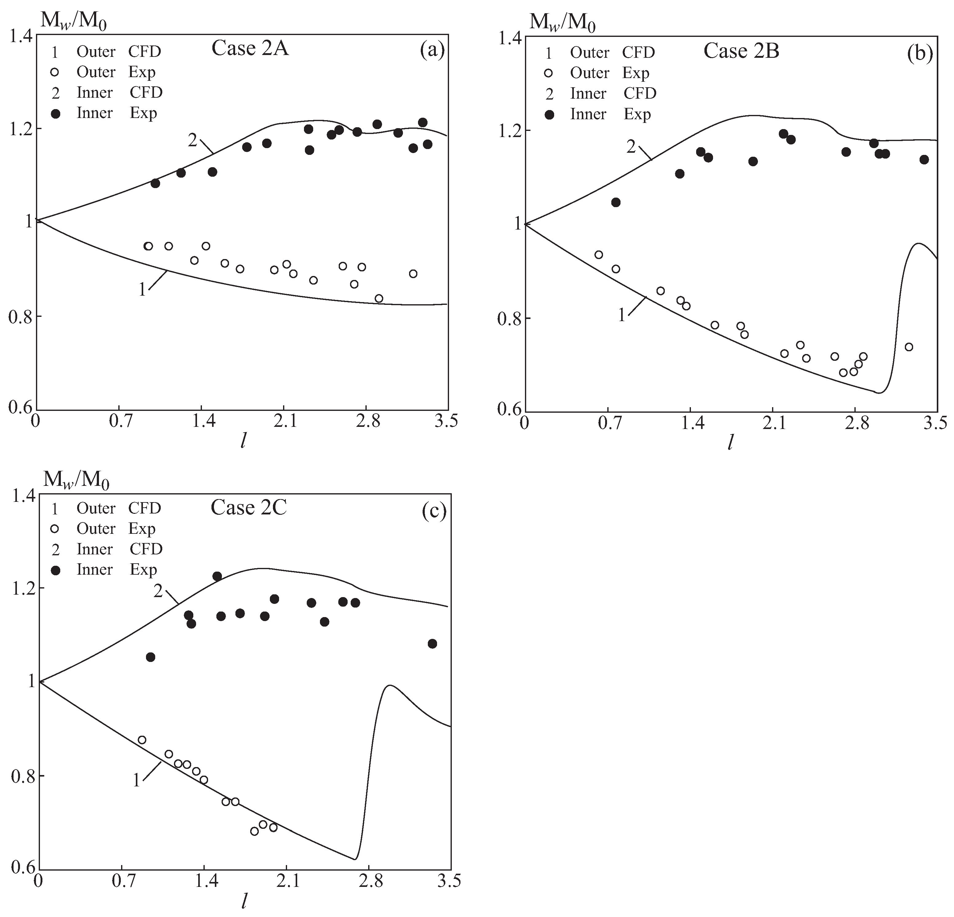
A comparison of calculated values of Mach numbers on inner and outer walls is shown in
Figure 19. Solid lines correspond to the results of numerical simulations, and symbols ○ and ● correspond to experimental data [
11]. The Mach number on outer wall reaches a maximum value of
, and on lower wall the minimum Mach number is
, which is slightly higher than the measured values. In all calculation options, the wave speed on lower wall becomes transonic. While the maximum Mach number on outer wall depends relatively weakly on initial wave speed, the Mach number on lower wall decreases from
in option 2A to approximately
in options 2B and 2C, having an almost constant value. The reason for this is that the triple point reaches inner wall, and the intensity of shock wave on upper wall decreases, and the intensity of shock wave on inner wall increases.
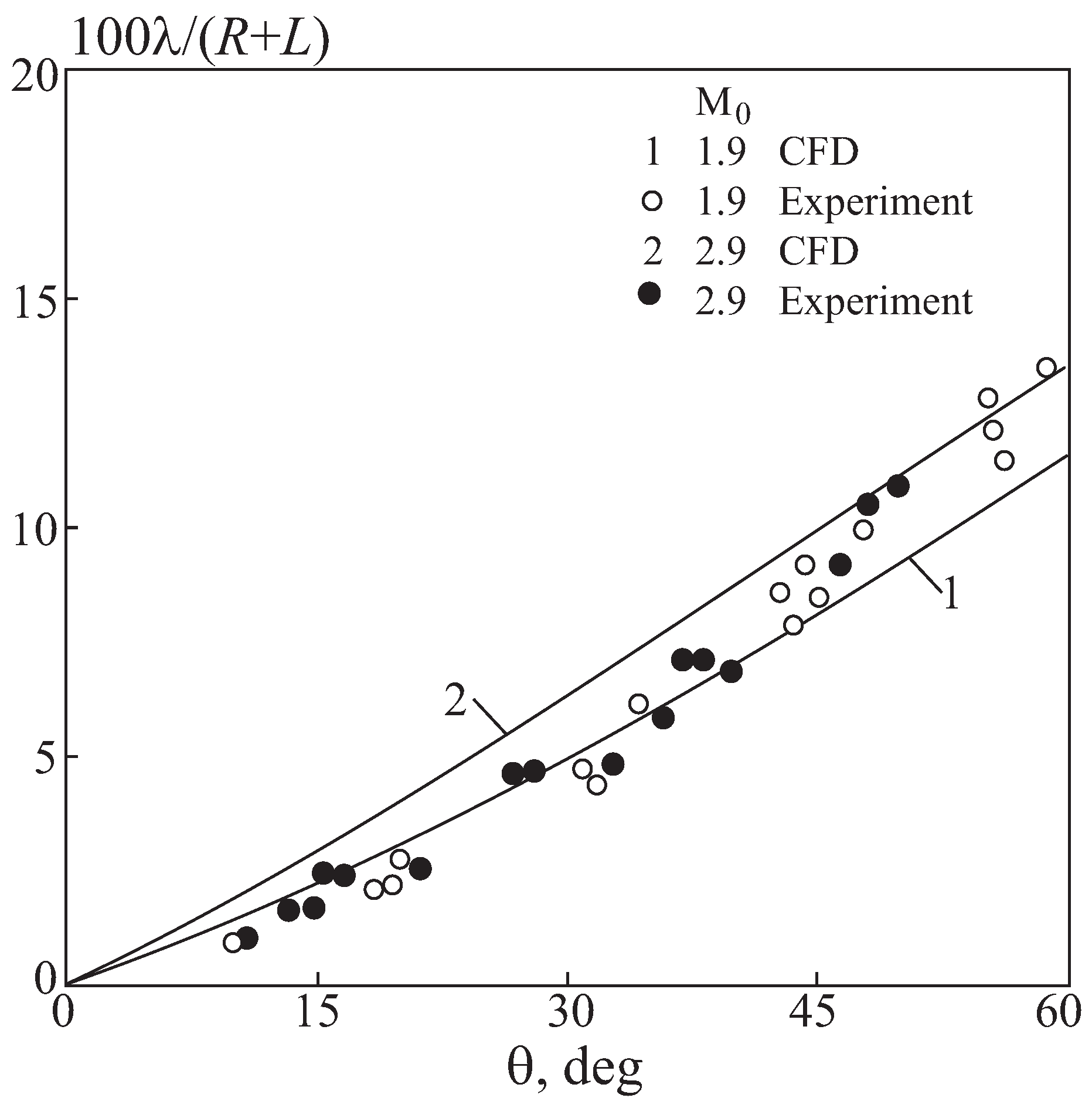
From a practical point of view, of interest is the size of the Mach stem and its modifications over time depending on intensity of initial wave and the size of annular gap. The size of Mach stem is a function of angular coordinate
corresponding to position of shock wave at time
t. The size of Mach stem as a function of angular coordinate, corresponding to options 2B and 2C (solid lines), is shown in
Figure 20 in comparison with data [
11]. The size of Mach stem is normalized to linear scale
.
For the annular channel of the smallest width, it was found that the front has a virtually straight profile, while the velocity along the outer and inner walls of the channel differs by less than 15% and has a smooth nature of change. With an increase in the radial distance between the inner and outer walls of the channel, a sharp change in the ratio of velocities on the inner and outer walls of the channel occurs. The difference between the average value of the ratio of shock wave propagation velocities on the inner and outer walls reaches 25%, increasing with an increase in the channel width.
To isolate geometric effects from incident strength, a controlled subset in which the incident shock Mach number was held constant across channels ( for B and for C) was performed. All thermodynamic, wall, and numerical settings were identical; only the annular geometry varied (curvature ratio). These matched Mach number cases complement the experiment-matched runs (where Mach number necessarily differs across rigs) and satisfy the principle of controlling variables. Results confirm that trends reported in the experiment-matched sets persist under fixed Mach number: inner-wall focusing, diffraction-induced attenuation, and the regular. Mach reflection transition remain monotonic functions of curvature, with peak inner-wall amplification varying by 5% between 1B and 1C at , and 7% at .
6. Conclusions
A numerical study of shock-wave propagation and diffraction in annular ducts has been performed using high-resolution inviscid CFD simulations. The curved geometry of the annular channel introduces flow features not observed in linear configurations, including asymmetric wave interaction, curvature-induced focusing, and strong dependence of reflection patterns on the radius of curvature. The results show that diffraction along the inner wall governs the overall attenuation and deformation of the incident shock, while reflection from the outer wall generates localized compression zones that influence the development and strength of the Mach stem. Comparison across geometries and inlet Mach numbers demonstrates that increasing curvature enhances inner-wall focusing and pressure amplification, whereas a wider annular gap promotes faster shock attenuation downstream. Numerical predictions agree closely with available experimental data, validating the computational approach and confirming that the essential features of shock reflection and triple-point motion are well captured.
Although the present study neglects viscosity and chemical reactions, the obtained results clarify the fundamental mechanisms that govern unsteady wave behavior in confined curved channels. The interplay between diffraction at the inner wall and compression near the outer wall provides a useful analogue for interpreting flow organization within rotating or continuous detonation combustors, where similar geometric effects contribute to front stability and local ignition. However, direct application of these findings to reactive detonations must be made with caution, as detonation structure and stability are largely determined by chemical kinetics and energy release.
Future work will extend this research to include the effects of external disturbances, localized energy deposition, and controlled wall motion. A configuration with a moving or partially permeable wall, whose velocity approaches the post-shock flow speed, is proposed to study flow compression, product removal, and potential stabilization of a reactive front. Verification of these concepts will require three-dimensional viscous simulations coupled with energy-release models to capture the full fluid–structure–reaction interaction. The present results, therefore, provide a validated foundation for such future investigations and contribute to the broader understanding of shock-wave behavior in curved, confined geometries relevant to advanced detonation-based propulsion systems.
