Abstract
Vacuum-assisted biopsy needle is an important tool for minimally invasive tissue sampling. Its procedural efficiency is largely compromised by the limited pneumatic efficiency and the recurrent tissue winding problem. In this study, a fluid dynamics model of vacuum-assisted biopsy is established, and its pneumatic performance is investigated. The analysis focuses on the interplay between pneumatic efficiency and structural design, particularly examining how geometric parameters influence the internal flow dynamics. The results demonstrate that the vacuum pressure applied linearly increases the flow rate. The main energy loss is located at the inlet area. Key findings reveal trade-offs between flow enhancement and winding risks, where anti-winding structures improve tissue winding but impair the pneumatic efficiency. The study can provide guidance for the structural optimization design of vacuum-assisted biopsy needles.
1. Introduction
Biopsy needles play an important role in extracting pathological soft tissues for disease diagnosis [1,2], and their performance directly influences the extraction efficiency [3,4] and diagnostic quality of the tissue samples [5,6]. Although progress has been made in improving puncture accuracy [7,8,9] and sample quality [10,11,12], systematic research on enhancing extraction efficiency remains rare. Vacuum-assisted biopsy (VAB) demonstrates significantly higher extraction efficiency than conventional core-needle biopsy [13], leading to its widespread adoption in clinical practice [14,15]. However, VAB devices occasionally suffer from insufficient suction or even needle clogging [16], potentially affecting procedural success. These issues significantly compromise its pneumatic performance and are primarily attributed to insufficient airflow within the needle, which hinders effective tissue extraction. Currently, commercial VAB systems primarily focus on publishing clinical outcome studies [15,17], with insufficient research conducted on their pneumatic performance, necessitating further exploration.
VAB commonly incorporates a coaxial needle design in which rotational motion of the inner cannula is utilized to enhance the capability of cutting tissue. However, it is demonstrated that this rotation cutting procedure will increase the risk of tissue winding [18,19,20]. The winding of tissue around the cannula can not only cause secondary trauma to the patient, but also lead to airflow obstruction and needle clogging. Additionally, the integrity of the tissue sample can be compromised, making it more difficult for pathologists to accurately diagnose the condition [21,22]. Existing solutions, such as the VAB products of Mammotome and EnCor, use a pendulum rotary cutting method to reduce the tissue winding or a double-layered outer cannula to avoid the airflow obstruction caused by tissue winding. But there are still issues with insufficient pneumatic performance at times. The more straightforward way to reduce the risk is to narrow the annular gap between the two cannulas, which can directly mitigate tissue winding. However, the pneumatic performance of VAB will be largely compromised since this gap is the necessary path of the airflow. Achieving an optimal balance between the pneumatic performance and risk of tissue winding remains an unresolved issue. Since the quantitative effects of the flow-related structural design of VAB on its pneumatic performance are not clear, the efficacy of needle design requires long periods of trial production and experimentation.
Computational fluid dynamics has been widely applied in the industrial field [23,24,25,26] and has become a powerful tool for analyzing fluid dynamics in medical devices [27,28]. Although CFD is widely used in cardiovascular systems [29,30,31], dental equipment [32,33], and thrombectomy tools [34,35,36], applications for VAB remain rare. Kamau and Njori [37] recently proposed that CFD optimization design can improve surgical outcomes. Instead, the study of other devices based on similar fluid mechanisms could suggest relevant insights. For instance, Abbas and Rafiq [38] demonstrated the influence of rich dimensionless parameters on fluid flow. Dai et al. [39] compared the effects of different aperture positions and lengths on the air flow inside the needle. Gao et al. [40] analyzed the oblique angle of the needle and improved its aerodynamic performance. Baasch et al. [41] determined the influence of different needle tips on the internal flow rate. These studies demonstrate that CFD simulation is an effective way for structural design in fluid-driven devices. With regard to VAB, a valid CFD model is necessary to reveal its flow characteristics and quantitatively study the influence of different parameters.
To provide a basis for the optimization of VAB regarding its pneumatic and tissue winding performance, this paper develops a computational model for the VAB and investigates the effects of the applied vacuum pressure and key structural parameters (annular gap, anti-winding structure) of the biopsy on its internal flow characteristics. The remainder of this paper is organized as follows. Section 2 briefly introduces the computational methodology, including model description, grid-independence analysis, and numerical verification. Section 3 presents the simulation results of the VAB under varied fluidic and structural conditions. Section 4 provides a comprehensive discussion. Conclusions are finally drawn in Section 5.
2. Methodology
2.1. Computational Model
In the present study, a typical structure is adopted, which consists of a coaxial inner cannula and outer cannula, as shown in Figure 1. Driven by an applied vacuum pressure at the end of the inner cannula, air is supplied from the annular gap, which enters the inner cannula through ventilation grooves to propel the extraction of the tissue.
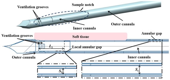
Figure 1.
Schematic illustration of the structure of the biopsy needle.
Key factors affecting the pneumatic performance of VABs are the applied vacuum pressure and structural design of the cannulas. The main structural parameters of the VAB, as well as the adopted vacuum pressure, are shown in Table 1. A typical length of 135 mm is set for the length of the two cannulas. The inner diameter of the outer cannula is also fixed. The outer diameter of the inner cannula is varied from 4.1 mm to 4.3 mm to adjust the annular gap. Additionally, the parameters of an anti-winding structure proposed in Section 3.3 are also listed in Table 1, and its geometric structure schematic is shown in Figure 2. The varied parameters are systematically analyzed through computational simulations to evaluate their individual effects on airflow characteristics.

Table 1.
Model parameters.
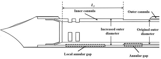
Figure 2.
Schematic illustration of the anti-winding structure.
2.2. Governing Equations and Solution Method
The model is a well-established and widely validated approach in industrial CFD, making it a suitable choice for simulating the internal flow within the biopsy needle. Its robustness and numerical stability provide a reliable foundation for analyzing airflow characteristics. A key advantage of this model is its relatively low computational cost compared to more complex alternatives such as Large Eddy Simulation. Since the pneumatic performance of VAB at the final steady state is required, the steady-state model is adopted. In the standard turbulence model, the equations for the turbulent kinetic energy and the turbulent dissipation rate are as follows:
where and are the Prandtl numbers corresponding to and ; is the turbulent viscosity coefficient, expressed as ; , , and are all empirical constant [42].
The pressure boundary conditions are employed. The vacuum pressure that varied from 30 kPa to 90 kPa is applied by the equivalent pressure difference between the inlet and outlet. The no-slip boundary conditions are applied for all the walls.
The open-source software Elmer (version 9.0) is used to solve the governing equations based on the finite element method (FEM). The calculation uses mixed velocity–pressure elements with quadratic velocity and linear pressure approximations, and nonlinearities are resolved through Newton–Raphson iterations, ensuring solution convergence and accuracy.
2.3. Mesh Convergence
The computational domain is meshed using Gmsh (version 4.0.4) with a hybrid grid approach to optimize both accuracy and efficiency. Near-wall areas are discretized using prismatic boundary layer meshes to properly resolve viscous sublayer dynamics, while tetrahedral elements are employed in the core flow areas. Special mesh refinement is implemented in critical areas, including the biopsy needle inlet and intake ports (as shown in Figure 3), ensuring adequate resolution in these areas.
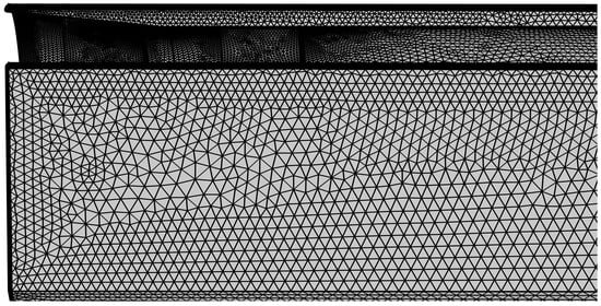
Figure 3.
Mesh refinement at the front section of the biopsy needle.
A grid independence analysis has been conducted. Four grid configurations with varying resolutions are compared. The obtained results are listed in Table 2. The error between the fine grid and the refined grid is 2.60% for the maximum flow velocity and no more than 0.15% for the overall flow rate. Compromising accuracy and computational cost, the configuration of fine grids is used in subsequent simulations.
Table 2.
Verification of grid independence.
2.4. Numerical Verification
The time-averaged velocity profile in fully developed turbulent flow exhibits a characteristic logarithmic distribution [43]. This behavior in smooth-walled circular pipes can be mathematically expressed as follows:
- (i)
- For the viscous sublayer :
- (ii)
- For the buffer layer :
- (iii)
- For the logarithmic layer :
The velocity distribution in the cross-section of the inner cannula of the VAB is compared with the theoretical velocity distribution in Figure 4. In the turbulent core area, the simulation results are in good agreement with theoretical predictions, with a maximum error of less than 5.4%. It is noted that there is a large deviation in the viscous sublayer. Due to high-Reynolds-number assumptions of the turbulence model, the established model fails to account for flow characteristics in near-wall low-Reynolds-number areas. Despite these discrepancies, the simulation results present consistency with the theoretical predictions across primary flow areas.
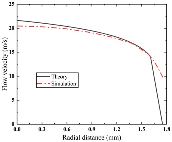
Figure 4.
Comparison of velocity distribution between simulation results and theoretical prediction.
3. Results
The simulation results of the varied vacuum pressure, annular gap, and anti-winding design are shown in this section. Their effects on the flow characteristics of the VAB in terms of velocity distribution, flow rate, and pressure loss are investigated to reveal their quantitative relationships and the related mechanism.
3.1. Effect of the Applied Vacuum Pressure
The applied vacuum pressure is the dominant factor in air flow within the biopsy needle. To assess its quantitative impact, flow fields under varying vacuum pressures are compared in Figure 5. Although the flow velocity distributions are similar in profile, the magnitude of the velocities differs markedly. Lower vacuum pressure yields a smaller high-velocity area due to a weak driving force. With the increase in the applied vacuum pressure, the high-velocity area expands, elevating the maximum flow velocity from 50.8 to 97.4 m/s. It is worth noting that sudden speed changes mainly occur near the ventilation groove of the needle, while most of the inlet and outlet areas maintain relatively stable flow velocities.
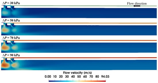
Figure 5.
Velocity distribution within the biopsy needle under varied vacuum pressures (S1 = 0.15 mm).
Higher flow velocity results in a larger flow rate, as expected. Notably, a near-linear relationship between the flow rate and vacuum pressure is observed in Figure 6. By increasing the applied vacuum pressure from 30 kPa to 90 kPa, the flow rate rises from 89.81 to 165.05 mL/s.
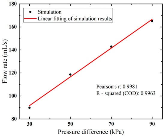
Figure 6.
Flow rates of the biopsy needle under varied vacuum pressure.
Additionally, it is observed in the pressure distribution (shown in Figure 7) that the gap between the inner and outer tubes, i.e., the annular gap, which is the narrowest path of the fluid flow, exhibits pronounced pressure changes. The pressure distribution in this area under varying vacuum pressures is compared in Figure 8. Clearly, the pressure decreases linearly with the flow distance, which aligns with the Darcy–Weisbach formula, indicating the pressure loss along the narrow gap. Notably, the higher applied vacuum pressure has a greater loss of pressure, since the increased fluid velocity causes higher energy loss.

Figure 7.
Pressure distribution at the front end of the biopsy needle at ΔP = 90 kPa.
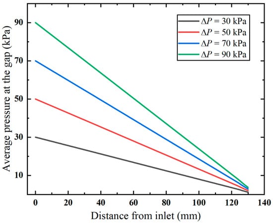
Figure 8.
Pressure distribution along the annular gap.
3.2. Effect of Annular Gap
It is observed in the previous section that the narrow annular gap is the main cause of the energy loss of airflow. The quantified effect of the gap (i.e., S1) is further investigated in this section. Figure 9 shows that the size of the annular gap has a significant influence on the velocity distribution of airflow. Narrower gaps reduce overall flow velocity, with maximum velocity dropping from 89.3 m/s to 52.6 m/s as S1 decreases from 0.12 mm to 0.05 mm. Meanwhile, wider gaps have more air flow through the front ventilation groove and present a different airflow distribution. Distinct high-velocity airflow occurs at S1 = 0.12 mm and 0.10 mm but nearly vanishes at S1 = 0.05 mm.
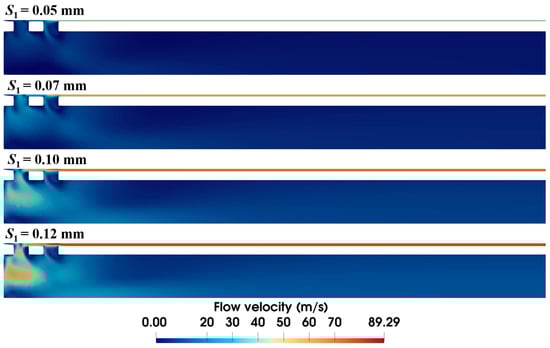
Figure 9.
Velocity distribution within the biopsy needle under varied annular gaps (ΔP = 90 kPa).
The annular gap has an impact not only on the local flow velocity but also on the overall flow rate. As evidenced in Figure 10, the flow rate follows the same trend as the variation in the annular gap under different pressures. The higher the pressure, the faster the flow rate increases. When the vacuum pressure is 90 kPa, the flow rate is significantly increased from 29.20 mL/s to 165.05 mL/s, with S1 increased from 0.05 mm to 0.15 mm. And this correlation exhibits a nonlinear positive relationship. The needle’s pneumatic performance is mainly limited by the annular gap, and a larger gap improves its suction rate. However, larger gaps increase the risk of tissue winding, requiring an optimized design to minimize this effect.
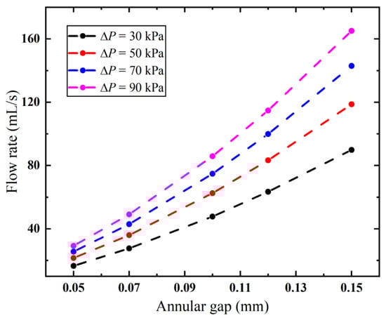
Figure 10.
Flow rates of the biopsy needle under varied annular gaps.
3.3. Effect of Anti-Winding Structure
It is found in our in vitro experiment that the occurrence of tissue winding is strongly related to the annular gap. However, simply reducing this gap is not a solution due to its negative impacts on the flow rate, as observed in Figure 10. Therefore, we design an anti-winding structure (Figure 2) by strategically enlarging the external diameter of the inner needle in the area of the sample notch, which only reduces the local annular gap where tissue winding occurs. This design aims to prevent the winding at the source while maintaining the flow rate as much as possible. To this end, how the diameter and length of the anti-winding structure affect the pneumatic performance of the biopsy needle is investigated in the following section.
3.3.1. Diameter of the Anti-Winding Structure
The diameter of the anti-winding structure directly relates to the local annular gap in the sample notch. As shown in Figure 11, expanding the diameter progressively shrinks the high-velocity area at the front end. In particular, at the diameter of 4.34 mm (i.e., S2 = 0.03 mm), the high-velocity area vanishes, and the flow velocity in the annular gap is also markedly decreased.
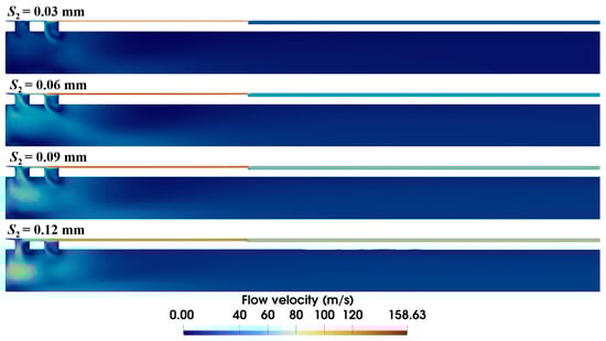
Figure 11.
Velocity distribution within the biopsy needle with varying diameters of the anti-winding structure (ΔP = 90 kPa, S1 = 0.15 mm, L2 = 10 mm).
Furthermore, we examine how the diameter affects the inlet gap pressure loss (Figure 12). The results show that both higher flow velocity and narrower flow gaps increase flow resistance. This causes faster pressure loss in the anti-winding structure than in pre-entry flow stages. Narrowed gaps dramatically amplify structural resistance, resulting in significant airflow energy dissipation and consequent flow rate attenuation.
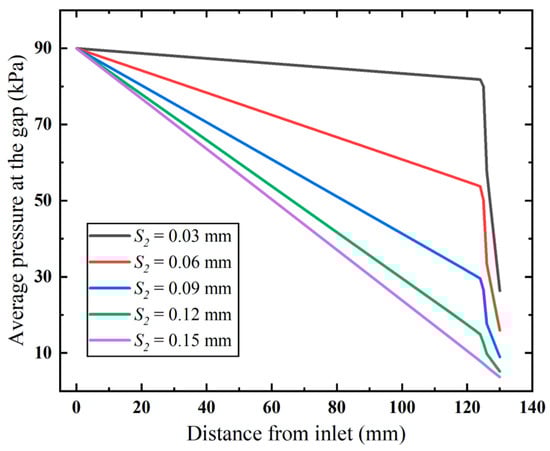
Figure 12.
Pressure distribution along the annular gap (ΔP = 90 kPa).
Correspondingly, the flow rate of the biopsy needle decreases with increased diameter, as shown in Figure 13. It can be observed that narrowing the local annular gap at the anti-winding structure under different pressures causes a progressively accelerating decline in flow rate. Importantly, compared to modifying the overall annular gap (Figure 10), the anti-winding structure better preserves the flow rate. When the vacuum pressure is 90 kPa, the biopsy needle achieves a flow rate exceeding 90 mL/s with a local annular gap of merely 0.06 mm (Figure 13), whereas the flow rate declines below 90 mL/s when employing the annular gap of 0.10 mm (Figure 10). Although further in vitro experiment needs to be carried out to examine its anti-winding efficacy, it suggests that the local annular gap can be appropriately designed so as to balance the performance of the biopsy needle in terms of anti-winding and suction performance.
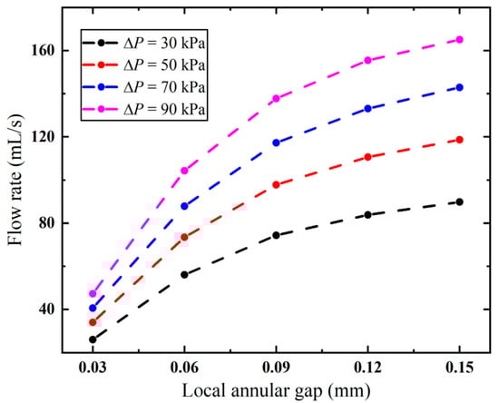
Figure 13.
Flow rates of the biopsy needle with varying diameters of the anti-winding structure.
3.3.2. Length of the Anti-Winding Structure
The length of the anti-winding structure also has a significant effect on the airflow dynamics, as shown in Figure 14. When the length is 1.5 mm, the anti-winding structure only covers the front ventilation groove of the inner needle, making most of the air flow through the rear ventilation groove. As the structure is extended to cover both grooves, the velocity distribution inside the inner needle remains almost identical, while the velocity at the local annular gap of the anti-winding structure progressively decreases with the increased length.
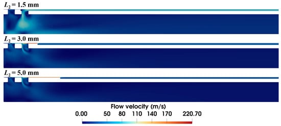
Figure 14.
Velocity distribution within the biopsy needle with varying lengths of the anti-winding structure (ΔP = 90 kPa, S1 = 0.15 mm, S2 = 0.03 mm).
As demonstrated in Figure 15, the biopsy needle has a lower flow rate with a longer anti-winding structure. This structure exhibits optimal flow performance when its length remains below 2.2 mm, as this configuration facilitates efficient airflow entry through the rear ventilation groove, thereby maintaining high flow rates. However, once the lengthened structure covers both ventilation grooves, the flow rate sharply decreases from 161.89 to 77.06 mL/s when the vacuum pressure is 90 kPa. Thereafter, the effect of the varied length becomes small, since the flow rate only decreases from 63.77 mL/s to 27.99 mL when the length is increased from 5 mm to 30 mm. When the length is 30 mm, the flow rates remain consistently low under all pressures.
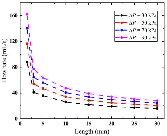
Figure 15.
Flow rates of the biopsy needle with varying lengths of the anti-winding structure.
4. Discussion
Numerical simulations are carried out to investigate the applied vacuum pressure and structural design of the biopsy needle on its pneumatic performance. The results show that the applied vacuum pressure serves as the primary driving factor, presenting a nearly linear relationship with the flow rate of the biopsy needle (Figure 6). The observed flow variation manifests as intensified pressure loss at the inlet channel (Figure 8). Although the Darcy–Weisbach formula is derived for circular pipes, its fundamental relationship between flow velocity and viscous resistance provides a conceptual framework for analyzing pressure gradients in the annular gap of biopsy needles. Specifically, increased flow velocity through this confined space elevates viscous resistance, thereby intensifying pressure loss. The focus of the investigation is on the vacuum pressure range of 30 kPa to 90 kPa. This range is clinically representative and is employed in biopsy procedures. Although the relationship may become nonlinear at extremes beyond 90 kPa, this region is not relevant to clinical application. The use of extremely high vacuum pressures would not only increase equipment cost, but also lead to tissue damage [44,45].
Although large efforts have been made to optimize the structure of the biopsy needles, the majority of studies focus on the cutting performance [46,47] and sample amount [48,49]. The relationships between design parameters and their resultant pneumatic efficacy remain unclear. Our results demonstrate that the structural design also has a significant influence on the pneumatic efficiency. Specifically, the annular gap between the cannulas is the most critical factor affecting the airflow of the biopsy needle. Compared to the baseline 0.03 mm configuration, when the applied vacuum pressure is 90 kPa, expanding the annular gap to 0.15 mm yields a dramatic 4.65-fold improvement in flow rate (as shown in Figure 10), since the expansion of the narrowest flow channel markedly reduces energy dissipation. However, simply increasing the annular gap could increase the risk of tissue winding. For structures involving rotary cutting, a larger annular gap leads to more tissue accumulation on the surface, thereby increasing the likelihood of winding. This winding phenomenon not only compromises the integrity of the biopsy sample, which may adversely affect pathological diagnosis, but also suppresses the flow rate by obstructing the flow area. Consequently, the design challenge evolves from maximizing the flow rate to optimizing the gap to balance these factors. The ideal configuration would be wide enough to minimize flow resistance yet narrow enough to prevent tissue adhesion. The quantitative relationship between pneumatic performance and tissue winding remains unclear and necessitates further experimental investigation. To address this trade-off, an anti-winding structure is proposed in this study, targeting the sample notch region where winding predominantly occurs. This design aims to reduce the winding without compromising the pneumatic performance, thereby achieving a balance between flow rate and winding risk.
The proposed anti-winding structure locally increases the outer diameter of the inner cannula to mitigate the risk of tissue winding. However, the resulting reduction in the local annular gap leads to a corresponding decrease in flow rate (Figure 13). As compared to adjusting the overall annular gap, the locally introduced anti-winding structure provides a superior flow rate (as confirmed by comparing Figure 13 to Figure 10). Nonetheless, a 0.03 mm local annular gap still causes a 71.3% reduction in flow rate relative to the 0.15 mm reference configuration in 90 kPa. Furthermore, we systematically evaluate the effect of the length of the anti-winding structure on the flow rate under a fixed 0.03 mm local annular gap condition. The results demonstrate a gradual decline in flow rate with increasing structure length, with the most pronounced reduction occurring when the length extends through the ventilation groove area (Figure 15). At shorter lengths, the ventilation groove leads to unobstructed airflow into the inner cannula. Although a shorter structure length maintains unobstructed airflow through the ventilation grooves, its limited length provides inadequate anti-winding functionality. The above results indicate a quantitative relationship between the anti-winding structure and the pneumatic performance. It is important to note that the CFD model assumes smooth walls. In reality, the surface roughness of the cannulas, particularly in the narrow annular gap, increases the flow resistance and leads to additional pressure losses. Moreover, surface roughness also influences the frictional interactions with soft tissue, potentially affecting the propensity for winding. Further experimental research is needed to quantify these impacts.
The present study offers insights into the pneumatic performance of VAB needles through CFD simulations and parametric analysis to provide design guidance. However, some limitations of this study should be noted. Although a simple benchmark test is applied to validate the developed model, experimental validation should be carried out to further confirm the accuracy of the predicted flow fields and pressure distributions. Furthermore, the pneumatic performance of VAB with varying structures is only compared in a tissue-free scenario, which does not account for the interaction between the tissue and fluid during the actual aspiration. The tissue–fluid interaction could alter the internal flow dynamics and the overall pneumatic efficiency. To that end, a two-way coupled fluid–structure interaction model should be further incorporated, as well as a constitutive model for the soft tissue.
5. Conclusions
In this work, a computational model is established to systematically evaluate the pneumatic performance of VAB, revealing critical insights into structural optimization. The results demonstrate that the applied vacuum pressure serves as the primary driver of pneumatic actuation, while energy loss predominantly occurs at the inlet area. Key findings highlight trade-offs in design parameters: increasing the annular gap enhances flow rates but elevates tissue winding risks, whereas the anti-winding structure mitigates tissue winding at the cost of reduced pneumatic efficiency. Our findings provide fundamental guidance for needle optimization, particularly in balancing flow characteristics with tissue winding. This study offers an approach for evaluating design modifications in biopsy devices.
Author Contributions
Conceptualization, Z.Z.; Methodology, C.L. and Z.Z.; Validation, C.L. and E.Y.; Data analysis, C.L. and J.W.; Interpretation, C.L., Z.Z. and J.W.; Writing—original draft, C.L. and Z.Z.; Writing—review and editing, Z.Z., E.Y. and S.M.; Supervision, Z.Z.; Writing—final approval, Z.Z.; Funding acquisition, Z.Z. and S.M. All authors have read and agreed to the published version of the manuscript.
Funding
This work was supported by the National Natural Science Foundation of China (Grant No. 12402294 and 52405251) and additionally supported by the Science and Technology Research Program of Chongqing Municipal Education Commission (Grant No. KJQN202401133).
Institutional Review Board Statement
Not applicable.
Informed Consent Statement
Not applicable.
Data Availability Statement
All data models that support the findings of this study are available from the corresponding author upon reasonable request.
Conflicts of Interest
No potential conflicts of interest were reported by the authors.
References
- Burgard, C.; Stahl, R.; de Figueiredo, G.N.; Dinkel, J.; Liebig, T.; Cioni, D.; Neri, E.; Trumm, C.G. Percutaneous CT Fluoroscopy-Guided Core Needle Biopsy of Mediastinal Masses: Technical Outcome and Complications of 155 Procedures during a 10-Year Period. Diagnostics 2021, 11, 781. [Google Scholar] [CrossRef]
- Winkler, W.L.; George, I.A.; Gandra, S.; Baker, J.C.; Tomasian, A.; Northrup, B.; Vander Velde, T.L.; Hillen, T.J.; Luo, C.; Imaoka, R. Diagnostic efficacy and clinical impact of image-guided core needle biopsy of suspected vertebral osteomyelitis. Int. J. Infect. Dis. 2024, 144, 107027. [Google Scholar] [CrossRef]
- Sakai, T.; Udagawa, H.; Kirita, K.; Nomura, S.; Itotani, R.; Tamiya, Y.; Sugimoto, A.; Ota, T.; Naito, T.; Izumi, H. Comparison of the efficiency of endobronchial ultrasound-guided transbronchial needle aspiration using a 22G needle versus 25G needle for the diagnosis of lymph node metastasis in patients with lung cancer: A prospective randomized, crossover study. Transl. Lung Cancer Res. 2021, 10, 3745. [Google Scholar] [CrossRef]
- Al Olaimat, M.S.; Al Qooz, F.S.; Alzoubi, Z.R.; Alsharaiah, E.M.; Al Murdif, A.S.; Alanazi, M.O. Efficiency of Fine-Needle Aspiration (FNA) in Relation to Tru-Cut Biopsy of Lateral Neck Swellings. Cureus 2024, 16, e64224. [Google Scholar] [CrossRef]
- Guan, C.; Wu, M.; Ye, J.; Liu, Z.; Mao, Z.; Lu, C.; Zhang, J. Macroscopic on-site quality evaluation of biopsy specimens to improve the diagnostic accuracy of endoscopic ultrasound-guided fine needle aspiration using a 22-gauge needle for solid lesions: A single-center retrospective study. Exp. Ther. Med. 2023, 26, 338. [Google Scholar] [CrossRef]
- Ye, X.; Tucker, C.; Gardner, C.; Redilla, A.; Uppal, G.; Binder, A.F. Assessment of the diagnostic accuracy of core needle biopsies in the diagnosis of lymphoma. Blood 2020, 136, 12–13. [Google Scholar] [CrossRef]
- Liu, C.; Wang, L.; He, X.; Xu, Y.; Lu, D.; Li, P.; Lv, R.; Feng, Y.; Liu, M.; Li, C. 1.0 T MR-guided percutaneous coaxial cutting needle biopsy in pancreatic lesion diagnosis. J. Magn. Reson. Imaging 2018, 48, 382–388. [Google Scholar] [CrossRef]
- Rehling, D.; Liu, J.; Stewart, K.; Pott, P.; Schiele, F. Investigation of vibration parameters for needle insertion force reduction. Curr. Dir. Biomed. Eng. 2020, 6, 608–611. [Google Scholar]
- Wenhao, W.; Changfeng, X.; Chunyang, P.; Zhixiang, H.; Jun, Z.; Panling, H. Effect of vibration frequency on frictional resistance of brain tissue during vibration-assisted needle insertion. Med. Eng. Phys. 2020, 86, 35–40. [Google Scholar]
- Zhong, J.; Allard, R.; Hewitson, D.; Weston, M.; Hulson, O.; Burbidge, S.; Lambie, H.; Kaye, T.; Wyatt, J.I.; Albazaz, R. A real-world study evaluating ultrasound-guided percutaneous non-targeted liver biopsy needle failures and pathology sample-quality assessment in both end-cut and side-notch needles. Br. J. Radiol. 2021, 94, 20210475. [Google Scholar] [CrossRef]
- Bang, J.Y.; Krall, K.; Jhala, N.; Singh, C.; Tejani, M.; Arnoletti, J.P.; Navaneethan, U.; Hawes, R.; Varadarajulu, S. Comparing needles and methods of endoscopic ultrasound–guided fine-needle biopsy to optimize specimen quality and diagnostic accuracy for patients with pancreatic masses in a randomized trial. Clin. Gastroenterol. Hepatol. 2021, 19, 825–835.e827. [Google Scholar] [CrossRef]
- Dong, Y.; Gao, L.; Sui, Y.; Mao, M.; Zhan, W.; Zhou, J. Comparison of ultrasound-guided fine-needle cytology quality in thyroid nodules with 22-, 23-, and 25-gauge needles. Anal. Cell. Pathol. 2021, 2021, 5544921. [Google Scholar] [CrossRef]
- Sekino, H.; Ishii, S.; Yamakuni, R.; Suenaga, H.; Kuroiwa, D.; Fukushima, K.; Ito, H. Conventional versus Aspiration-type Needles in CT-guided Biopsy for Chest Pathologies/Lesions: A Comparative Study. Curr. Med. Imaging 2024, 20, e180523217058. [Google Scholar] [CrossRef]
- Elfgen, C.; Varga, Z.; Breitling, K.; Pauli, E.; Schwegler-Guggemos, D.; Kampmann, G.; Kubik-Huch, R.A.; Leo, C.; Lepori, D.; Sonnenschein, M.; et al. Long-Term Follow-Up of High-Risk Breast Lesions at Vacuum-Assisted Biopsy without Subsequent Surgical Resection. Breast Care 2024, 19, 62–72. [Google Scholar] [CrossRef]
- Valizadeh, P.; Jannatdoust, P.; Shahsavarhaghighi, S.; Rouzbahani, M.; Golezar, M.H.; Sadighi, N. Ultrasound-Guided Vacuum-Assisted Breast Biopsy for Breast Intraductal Lesions: A Meta-Analysis of Underestimation and Pathological Nipple Discharge Cure Rates. Arch. Breast Cancer 2024, 11, 13–26. [Google Scholar] [CrossRef]
- Bloemberg, J.; van Wees, S.; Kortman, V.G.; Sakes, A. Design of a wasp-inspired biopsy needle capable of self-propulsion and friction-based tissue transport. Front. Bioeng. Biotechnol. 2025, 12, 1497221. [Google Scholar] [CrossRef]
- Hu, S.; Wang, Y.; Liu, W.; Fan, Y.; Luo, X.; Huo, H.; Wu, Y. The Efficacy of Traditional Surgery Versus Minimally Invasive Surgery in Non-Lactation Mastitis Patients: A Retrospective Data Analysis. Ann. Ital. Chir. 2025, 96, 1064–1070. [Google Scholar] [CrossRef]
- Lin, C.-L.; Huang, Y.-A. Simultaneously reducing cutting force and tissue damage in needle insertion with rotation. IEEE Trans. Biomed. Eng. 2020, 67, 3195–3202. [Google Scholar] [CrossRef] [PubMed]
- Yen, C.-J.; Huang, Y.-A.; Lin, C.-L. Using simulation to study cutting force in biopsy needle insertion with bi-directional rotation. J. Mech. Med. Biol. 2019, 19, 1940020. [Google Scholar] [CrossRef]
- Lin, C.-L.; Lan, G.-J. A computational approach to investigate optimal cutting speed configurations in rotational needle biopsy cutting soft tissue. Comput. Methods Biomech. Biomed. Eng. 2019, 22, 84–93. [Google Scholar] [CrossRef] [PubMed]
- Itonaga, M.; Ashida, R.; Kitano, M. Updated techniques and evidence for endoscopic ultrasound-guided tissue acquisition from solid pancreatic lesions. DEN Open 2024, 5, e399. [Google Scholar] [CrossRef]
- Constantinescu, A.; Stoicescu, E.R.; Iacob, R.; Chira, C.A.; Cocolea, D.M.; Nicola, A.C.; Mladin, R.; Oancea, C.; Manolescu, D. CT-Guided Transthoracic Core-Needle Biopsy of Pulmonary Nodules: Current Practices, Efficacy, and Safety Considerations. J. Clin. Med. 2024, 13, 7330. [Google Scholar] [CrossRef]
- Abbas, Z.; Rehman, A.U.; Khaliq, S.; Rafiq, M.Y. Flow dynamics of MHD hybrid nanofluid past a moving thin needle with a temporal stability test: A Galerkin method approach. Numer. Heat Transf. Part B Fundam. 2023, 84, 329–347. [Google Scholar]
- Abbas, Z.; Ahmad, S.; Rafiq, M.Y. Numerical simulation of two-dimensional unsteady flow nanofluid inside a rectangular pipe with variable pressure gradient. Numer. Heat Transf. Part B Fundam. 2024, 1–20. [Google Scholar] [CrossRef]
- Khaliq, S.; Abbas, Z.; Junjua, M.-u.-D.; Ram, R.; Shahzad, H.; Rafiq, M.Y. Numerical assessment of thin layer coating of non-Newtonian fluid during blade coating process with MHD effects. Multidiscip. Model. Mater. Struct. 2025, 21, 462–479. [Google Scholar] [CrossRef]
- Hasnain, J.; Ali, Z.; Rafiq, M.Y.; Abbas, Z. A computational study on the sensitivity of slip constraints in the blade coating process of an electrically conducting oldroyd 4-constant fluid. J. Plast. Film. Sheeting 2025, 41, 114–136. [Google Scholar] [CrossRef]
- Li, Y.; Wang, H.; Liu, X.; Xi, Y.; Sun, A.; Wang, L.; Deng, X.; Chen, Z.; Fan, Y. Comprehensive study on simulation, performance evaluation and optimization strategies for blood pumps. Eng. Appl. Comput. Fluid Mech. 2024, 18, 2369690. [Google Scholar] [CrossRef]
- Abbas, Z.; Arslan, M.S.; Rafiq, M.Y. Numerical investigation of cilia beating modulated flow of magnetized viscous fluid in a curved channel with variable thermal conductivity. Alex. Eng. J. 2024, 97, 230–240. [Google Scholar] [CrossRef]
- Dong, D.; Jiang, J.; Li, D. Numerical Analysis of a Novel Rotating Piston Blood Pump Based on CFD. J. Phys. Conf. Ser. 2023, 2610, 012037. [Google Scholar] [CrossRef]
- Mohammadi, R.; Karimi, M.S.; Raisee, M.; Sharbatdar, M. Probabilistic CFD analysis on the flow field and performance of the FDA centrifugal blood pump. Appl. Math. Model. 2022, 109, 555–577. [Google Scholar] [CrossRef]
- Puentener, P.; Schuck, M.; Kolar, J.W. CFD Assisted Evaluation of In Vitro Experiments on Bearingless Blood Pumps. IEEE Trans. Biomed. Eng. 2021, 68, 1370–1378. [Google Scholar] [CrossRef] [PubMed]
- Li, X.; Mak, C.M.; Wai Ma, K.; Wong, H.M. How the high-volume evacuation alters the flow-field and particle removal characteristics in the mock-up dental clinic. Build. Environ. 2021, 205, 108225. [Google Scholar] [CrossRef] [PubMed]
- Phonsahwat, T.; Thitasomakul, S.; Tianviwat, S.; Morris, J.; Tekasakul, P.; Dejchanchaiwong, R. Using computational fluid dynamics to minimize droplet dispersion in intraoral suction devices with a dental triple syringe. Build. Environ. 2025, 273, 112699. [Google Scholar] [CrossRef]
- Chitsaz, A.; Nejat, A.; Nouri, R. Three-Dimensional Numerical Simulations of Aspiration Process: Evaluation of Two Penumbra Aspiration Catheters Performance. Artif. Organs 2018, 42, E406–E419. [Google Scholar] [CrossRef]
- Good, B.C.; Simon, S.; Manning, K.; Costanzo, F. Development of a computational model for acute ischemic stroke recanalization through cyclic aspiration. Biomech. Model. Mechanobiol. 2019, 19, 761–778. [Google Scholar] [CrossRef]
- Talayero, C.; Romero, G.; Pearce, G.; Wong, J. Numerical modelling of blood clot extraction by aspiration thrombectomy. Evaluation of aspiration catheter geometry. J. Biomech. 2019, 94, 193–201. [Google Scholar] [CrossRef]
- Kamau, J.; Njori, P. Optimizing Fine Needle Design to Minimize Needle Tract Seeding in Cancer Diagnosis: A Computational Fluid Dynamics Study. In Proceedings of the 7th Annual International Conference 2024, Virtual, 27–28 March 2024. [Google Scholar]
- Abbas, Z.; Rafiq, M.Y. Numerical Simulation of Thermal Transportation with Viscous Dissipation for a Peristaltic Mechanism of Micropolar-Casson Fluid. Arab. J. Sci. Eng. 2022, 47, 8709–8720. [Google Scholar] [CrossRef]
- Dai, Y.; Wang, S.; Gao, J.; Liu, Q.; Xiong, Z.; Gao, Y. The effects of aperture position and length in side-vented needles on root canal irrigation: A computational fluid dynamics study. Comput. Biol. Med. 2024, 179, 108940. [Google Scholar] [CrossRef]
- Gao, J.; Dai, Y.; Long, Z.; Min, Y.; Shen, Y.; Gao, Y. Optimization of Side-vented Root Canal Irrigation Needle Design: Aperture Bevel Angle and Configuration Analysis using CFD and Multicriteria Decision Analysis with In Vitro Validation and C-shaped Canal Simulation. J. Endod. 2025, 51, 1285–1293. [Google Scholar] [CrossRef]
- Baasch, A.; Ramírez-Muñoz, A.; Navarrete, N.; Navarro-Candel, M.; Koury-González, J.M.; Esteves-Nieves, O.; Vieira, G.C.S.; Pérez, A.R. Influence of irrigation needle design on cleaning efficiency in 3D mandibular molar models. Odontology 2025, 113, 1180–1188. [Google Scholar] [CrossRef]
- Liu, H.; Kong, Z.; Li, G.; Chen, C.; Zhao, Y.; Zhang, S. Uncertainty quantification of the standard k-ε turbulence model closure coefficients in predicting aerodynamics of high-speed train. Eng. Appl. Comput. Fluid Mech. 2024, 18, 2430658. [Google Scholar] [CrossRef]
- Salama, A. Velocity Profile Representation for Fully Developed Turbulent Flows in Pipes: A Modified Power Law. Fluids 2021, 6, 369. [Google Scholar] [CrossRef]
- Hueftle, M.G.; Haaga, J.R. Effect of suction on biopsy sample size. Am. J. Roentgenol. 1986, 147, 1014–1016. [Google Scholar] [CrossRef] [PubMed][Green Version]
- Kreula, J.; Virkkunen, P.; Bondestam, S. Effect of suction on specimen size in fine-needle aspiration biopsy. Investig. Radiol. 1990, 25, 1175–1181. [Google Scholar] [CrossRef]
- Zhu, X.; Ma, Y.; Xiao, X.; Lu, L.; Xiao, W.; Zhao, Z.; Ren, H.; Meng, M.Q.-H. Design and evaluation of a novel biopsy needle with hemostatic function. Front. Mech. Eng. 2023, 18, 22. [Google Scholar] [CrossRef]
- Lin, C.-L.; Huang, Y.-M.; Luo, Z.-Y.; Hsieh, Y.-H. A Novel Biopsy Needle with Double Concave-Curved Cutting Edges. IRBM 2023, 44, 100783. [Google Scholar] [CrossRef]
- Berg, W.A.; Krebs, T.L.; Campassi, C.; Magder, L.S.; Sun, C. Evaluation of 14-and 11-gauge directional, vacuum-assisted biopsy probes and 14-gauge biopsy guns in a breast parenchymal model. Radiology 1997, 205, 203–208. [Google Scholar] [CrossRef]
- Cicione, A.; Cantiello, F.; De Nunzio, C.; Tubaro, A.; Damiano, R. Prostate biopsy quality is independent of needle size: A randomized single-center prospective study. Urol. Int. 2012, 89, 57–60. [Google Scholar] [CrossRef]


Disclaimer/Publisher’s Note: The statements, opinions and data contained in all publications are solely those of the individual author(s) and contributor(s) and not of MDPI and/or the editor(s). MDPI and/or the editor(s) disclaim responsibility for any injury to people or property resulting from any ideas, methods, instructions or products referred to in the content. |
© 2025 by the authors. Licensee MDPI, Basel, Switzerland. This article is an open access article distributed under the terms and conditions of the Creative Commons Attribution (CC BY) license (https://creativecommons.org/licenses/by/4.0/).