Article

Design of Ultra-High-Aperture Dual-Range Athermal Infrared Objectives

by
Grigoriy Isaevitch Greisukh
1,*,
Il’ya Anatolievich Levin
2 and
Eugeniy Grigorievich Ezhov
1
1
Penza State University of Architecture and Construction, 440028 Penza, Russia
2
PJSC “Krasnogorsky Zavod”, 143400 Krasnogorsk, Russia
*
Author to whom correspondence should be addressed.
Photonics 2022, 9(10), 742; https://doi.org/10.3390/photonics9100742
Submission received: 12 September 2022 / Revised: 4 October 2022 / Accepted: 7 October 2022 / Published: 8 October 2022
(This article belongs to the Special Issue Recent Advances in Optical Diffraction and Imaging)

Abstract

:
We present a technique that includes the principles of selecting the layout of the optical scheme and recommendations for the choice of the initial design parameters for designing ultra-high-aperture dual-range athermal infrared objectives. The versatility and efficiency of the proposed technique are demonstrated using examples of the design of the refractive and refractive-diffractive version of the objectives, and the obtained optical performance is discussed.

1. Introduction

The recent successes in the improvement of the matrix photodetectors of infrared (IR) radiation have stimulated the development of multispectral IR systems with a single entrance pupil. This has led to new opportunities in realizing the high spectral sensitivity of the microbolometers in the extended spectral region, thereby covering the medium-(MWIR) and long-wave (LWIR) ranges (Δλ = 3–5 and 8–12 µm, respectively) [1,2,3].
In the development of the dual-range IR objectives with an uncooled receiver, the main difficulty lies in providing a large aperture along with suppressing the chromatic aberrations and thermal refocusing. For the thermal refocusing, the existing methods of materialization enable the minimization of the effect of the temperature changes on the qualitative characteristics of the image that is formed by the optical channel. While only the active method [4,5], which involves the mechanical movement of the system components, is used to compensate for the thermal defocusing, passive optical, or mechanical methods are preferable for objectives with a fixed effective focal length. The passive optical method is based on the selection of the optical materials and construction elements for the lens [4,6], but the mechanical method is based on the development of an additional mechanical design of a two-layer or multilayer thermal compensator [4,7].
The chromatic aberrations of the optical systems operating in several spectral ranges can be corrected by using only refractive lenses in the optical scheme and by including a diffractive optical element (DOE) in the scheme. Such an element transforms the incident wavefront because of the effect of light diffraction on a relief sawtooth microstructure, which is experienced, for example, on the surface of a refractive lens [8,9]. A significant inverse DOE dispersion, which is characterized by a negative dispersion coefficient, provides tangible advantages to refractive-diffraction schemes. Thus, in particular, a previous study [9] showed that in the double IR range, the required degree of correction of the longitudinal chromatism can be achieved with a three-lens high-aperture refractive-diffractive objective.
This study presents a technique that facilitates the design of ultra-high-aperture dual-range athermal IR objectives that are of a simple design. The examples of designing refractive and refractive-diffractive objectives have been used to justify the versatility and effectiveness of the proposed technique.

2. Proposed Principles and Recommendations

The proposed methodology, which includes the principles and recommendations that are outlined below, is based on dilatometry, the laws of geometric optics, the theory of aberrations, as well as the scalar and electromagnetic theories of diffraction.
The proposed universal principle of the layout of ultra-high-aperture objectives is based on an the optical scheme that includes an aberration corrector and a power component. In this case, the aberration corrector is located in front of the power component and it consists of two elements that are separated by a significant air gap d1 (see Figure 1).
To minimize the size of the front lens, the entrance pupil or aperture stop should be placed near the top of its first surface. For the aberration correction in the region of monochromatic aberrations for the ultra-high-aperture systems, aplanaticity is of fundamental importance, assuming that there is an absence of the spherical and comatic aberrations near the optical axis.
A sufficient level of correction of the chromatic aberrations may result in the elimination of a chromatic focal shift only for the two extreme wavelengths of the working spectral range; this is called achromatization. This is assumed considering the design features of the photocell arrays of the microbolometer, which do not enable spectral selectivity in the read signal. In addition, it is based on the opacity of the atmosphere in the range of 5.5–7.0 μm because of the absorption of the radiation by water vapor [10]. We also considered the high values of the dispersion coefficients in the MWIR subrange (ν > 107) and a significant difference in the dispersion coefficients in the LWIR subrange (22 < ν < 784) for the technological and commercially available IR materials that are transparent in a wide spectral range (see Table 1).
The elimination of the thermal defocusing to maintain the high optical performance of the objective under the conditions of a significant difference in operating temperatures is expediently solved by the method of passive optical athermalization. This eliminates the mechanical movement of the elements of the optical channel and minimizes its overall dimensions.
Assuming that the initial configuration of the objective consists of thin elements that are separated by air gaps (see Figure 1), and the optical power of this system at the calculated (main) wavelength λ ¯ of a given spectral range is constant, then the passive athermalization condition in combination with achromatization and the aplanaticity requirement can be written as a system of four equations:
j = 1 J h j φ j = h 1 Φ s F t m a x s F t m i n = 1 + α m o u n t t m a x t m i n j = 1 J h j 2 φ j ν j = 0 Φ = sin u J + 1 h 1
where h1 and hj are the heights of incidence of the first (aperture) paraxial ray on the first and j-th optical element, respectively; φj is the optical power of the j-th element; Φ is the total optical power of the objective; s′F′(tmax) and s′F(tmin) are the back focal length at the maximum (tmax) and minimum (tmin) values of the operating temperature interval, respectively; αmount is the thermal coefficient of expansion (TCE) of the construction material; νj is the dispersion coefficient of the j-th optical element; uJ + 1 is the angle of the aperture ray in the image space for the entire objective.
In this case, all of the optical powers of the elements and the effective focal lengths that are included in system (1) must be considered at a wavelength λ ¯ , and the dispersion coefficients are calculated for λ ¯ and the extreme wavelengths of the working spectral range.
By applying the Formulas (2) and (3) for calculating the path of the first (aperture) paraxial ray, one can easily pass from the heights of incidence hj to the distances between the elements dj, and an expression for the back focal length can be obtained:
u j + 1 = u j + h j φ j ,
h j + 1 = h j u j + 1 d j ,
s F = h J u J + 1 .
The changes in the optical power that depend on the range of the operating temperatures in the cases of a refractive lens and DOE, respectively, are [14]:
φ R L t m a x = φ R L t m i n 1 + υ t , λ t m a x t m i n ,
φ D O E t m a x = φ D O E t m i n 1 + α D O E t m a x t m i n 2 ,
where υt,λ is the thermo-optical constant of the refractive lens material; αDOE is the TCE of the DOE substrate material.
Assuming that the air gap between the aberration corrector and the power component is d2→0 (see Figure 1), then setting the values of the effective and back focal lengths of the objective would enable the selection of the materials of the lenses and construction details of the materials to minimize the optical powers of the individual lenses and reduce their contribution to the monochromatic aberrations. To achieve the same results, numerous steps are recommended.
First, to achieve athermalization, the power component should be made of materials with low values in their thermo-optical constant. Such commercially available optical materials are chalcogenide glasses. Despite that they are mainly used in the long-wavelength IR region (8–12 μm) optical systems [15,16], the transparency windows of these materials also cover the mid-IR range (3–5 μm).
This enables the use of chalcogenide glasses in the development of dual-range IR objectives, while also retaining the possibility of optical channel athermalization. In addition, the processing of chalcogenide glasses allows the use of modern shaping methods that are based on precision stamping, which is advantageous in replicating lenses with aspherical refractive surfaces.
Second, even if the power component is made of chalcogenide glasses, to compensate for the change in its back focal length, the negative optically weak corrective component should include that are lenses made of materials with a thermo-optical constant that is significantly higher than those for the chalcogenide glasses. Such materials are optical crystals. If we consider that the correction component is also designed to provide the achromatization of the lens, then the DOE should be included in this component in the refractive-diffractive version of the objective.
However, in this case, a real positive effect of using the DOE can be achieved only if the dependence of the diffraction efficiency (DE) of the element on the wavelength and angle of incidence of the radiation on it is suppressed. Therefore, the DOE microstructure is constructed as a double-relief two- or even three-layered structure [9,17]. The problem is exacerbated when we are using a refractive-diffractive lens in the conditions of a significant difference in its operating temperatures. In this case, it is necessary to ensure that the multilayer microstructure maintains its mechanical strength at a high DE in a wide range of its operating temperatures. Thus, the layer materials that are transparent in the dual IR range those which and differ significantly in both the refractive indices and the dispersion properties should have an almost equal TCLE. The latter circumstance practically excludes the use of diffractive microstructures in the spectral region that is under consideration, and the layers of the arcs that should be in direct mechanical contact with each other. Therefore, the most acceptable layout of the DOE microstructure is a two-layer microstructure with two internal sawtooth reliefs which is shown in Figure 2. Its reliefs are made on the flat surfaces of the material substrates, which differ in their dispersion properties. Usually it is a pair of crown- and flint-like optical materials [9,17,18,19].
The choice of the best pair of optical materials for the microstructure and the assessment of the optimal depth of the microstructure reliefs clearly depends on the choice of an appropriate criterion. When the DOE is used in an imaging optical system in which the diffraction of the radiation into the side orders is undesirable at any wavelength in the working spectral range, then the use of the criterion that has been proposed in a previous study [18] is a good choice. According to this criterion, a pair of materials and the depth of the reliefs are considered optimal if they enable the maximum possible value of the DE at the point of its minimum—DEmin—in the working spectral range and in a given range of radiation angles of incidence. This value can ensure that the decrease in the contrast in the image that is formed by the optical system because of the out-of-focus emission of secondary diffraction orders is suppressed to an acceptable level. This criterion has been successfully used in several previous works (for example, [20,21]).
When the composition of the optical scheme of an objective with a DOE is performed, then it should be considered that even at the optimal choice of the optical materials for the layers and depths of the reliefs H1 and H2, the DEmin of a two-layer two-relief microstructure depends primarily on the width of the interval of the angles of the incidence of radiation Δθ, and secondly on the value of the ratio of the period microstructure to the total depth of its reliefs P = Λ/(H1 + H2). The DEmin decreases with an increasing Δθ and it increases with an increasing P. These two circumstances restrict the location of the DOE in the optical scheme of the objective and the minimum period in its microstructure [22].
Here, we demonstrate the efficiency and versatility of the proposed principle of the composition and provide recommendations for the choice of optical materials and aberration correction using the examples of designing simple refractive and refractive-diffraction versions of ultra-high-aperture dual-range athermal IR objectives.
The values of the main parameters of the objectives are considered as follows: the f′ = 40 mm; the half-field angle ≤ 9.75°; the relative aperture D/f′ > 1.4; the back focal length is in the range f′ > s′F > 10 mm. The radiation detector is an uncooled microbolometer Bird 640 Ceramic Packaging BB Wide-Band [23] with a format of 640 × 480 and a pixel size of 17 μm. The operating temperature is limited to the range of −40–60 °C.
For the working spectral range, based on the results of a previous study [24] for a dual-range antireflection coating, we consider the edge values of the wavelengths as follows: λmin = 3.4 µm and λmax = 11.4 µm, with the inner boundaries of the subranges λ1 = 5.2 µm and λ2 = 7.5 µm, respectively. For the given spectral regions, the transmittance of the antireflection coating model does not fall below 99% at the normal incidence and below 97% at the radiation incidence angles that are up to 30°.
Among the solutions of the system of equations (1), two sets differed in the smallest modulus of the optical powers of the individual lenses: {φ1 = −0.446 m−1 (Germanium), φ2 = −20.275 m−1 (ZnS), and φ3 = 105.094 m−1 (IRG24)}; {φ1 = −1.617 m−1 (ZnS), φ2 = −4.497 m−1 (Germanium), and φ3 = 93.219 m−1 (IRG24)}. These kits were obtained assuming that the aluminum with the TCE αmount = 23 × 10−6 K−1 is used for the objective construction elements.
Owing to the limited choice of the optical materials with the required ratio of parameters, namely, of refractive index, dispersion coefficient, thermo-optical constant, and the TCE, which could enable their use in a single-lens power component, the optical power of this component in both of the sets significantly exceeds the total optical power of the objective. Therefore, to realize a relative aperture of at least D/f′ > 1.4, the power component that is used should be a dual-lens, and in the optimization process, it is more rational to distribute the aberration load between the power and correction components.
The negative value of the optical power of the first lens of the two-lens correction component with positive values of the effective focal length and the back focal length of the objective as a whole will lead to a negative value of the air gap d1 (see Figure 1). To avoid this, the first lens of the correction component should be replaced by two optical elements that are separated by an air gap. Thus, the correction component becomes a three-element one with the distance between the second and third elements tending toward zero. In the case of the refractive-diffractive version of the objective, the second and third elements of the corrective component will be the DOE and refractive lens, respectively, on the flat front surface of which the relief of the DOE microstructure will be made.
Thus, obtaining the initial design parameters of the optical scheme for a subsequent optimization entails the following steps:
  • Select the values of the main parameters of the developed objective, based on the requirements for the entire device.
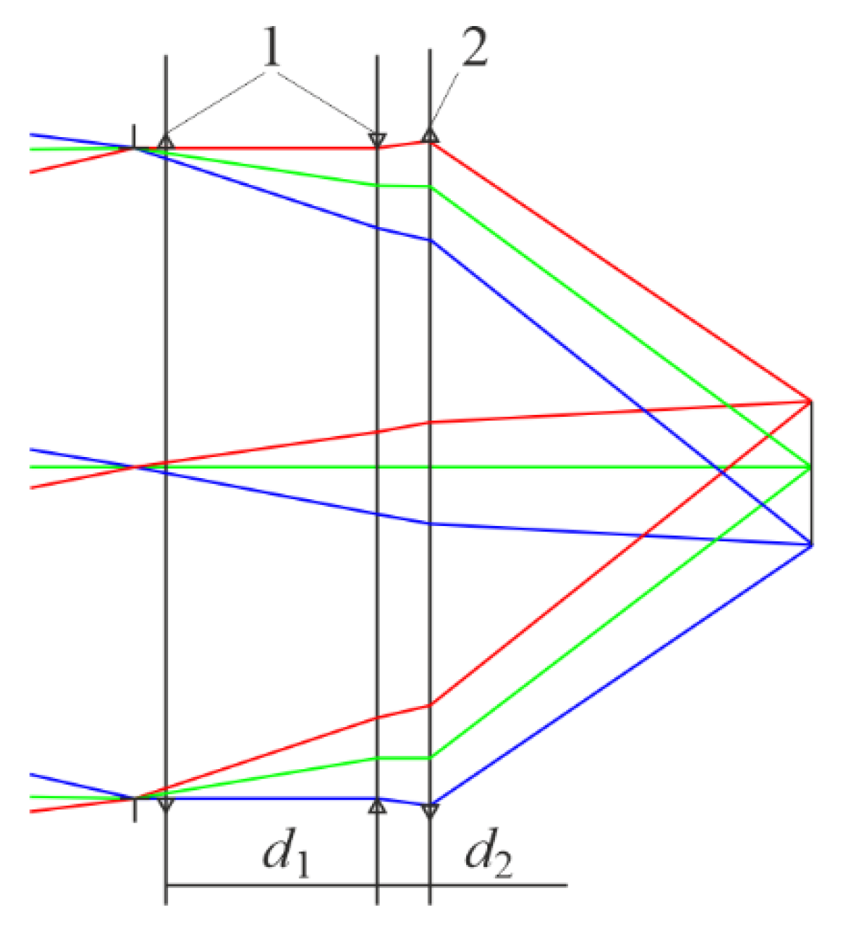
  • Following the relevant recommendations that are presented above, select the lens and construction materials that minimize the optical powers of individual lenses in the initial configuration (Figure 1). To this end, use the system of Equation (1), preliminarily considering d2→0.
  • Based on the obtained values of the optical powers of individual lenses and to achieve ultra-high relative aperture, separate the power component according to the relevant recommendations that are presented above.
  • Ensure d1 > 0 by replacing the first lens of the correction component according to the relevant recommendations above.
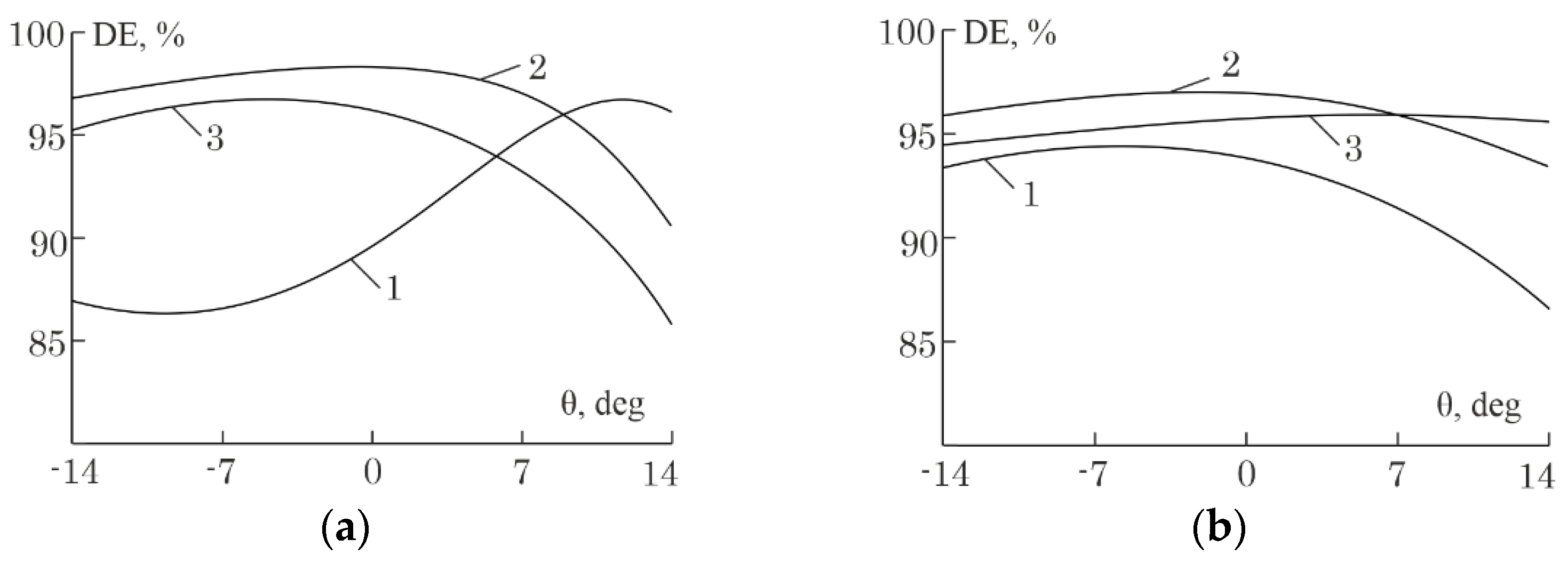
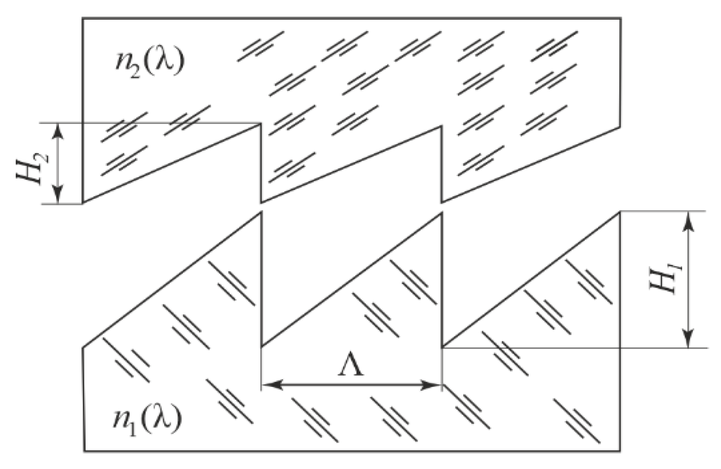
  • For the refractive-diffractive version of the objective, select the materials for the two-layer DOE microstructure to suppress the spectral and angular selectivity of the DE.
  • Optimize the optical scheme that has been obtained as a result of steps 1–5 using a commercial optical design software. Execute the aplanatic condition, and maximize the relative aperture.

3. Results

The first and second sets of the aforementioned parameters (considering the specified bifurcation of single lenses) were used as the basis for the initial solutions for subsequent optimization in the ZEMAX optical design program [25]. As a result of the optimization, the refractive and refractive-diffractive variants of an ultra-high-aperture athermal dual-range IR objective were obtained. Figure 3 and Figure 4 present the optical layout, and Table 2 and Table 3 list the design parameters.
The conic constant and the aspheric polynomial coefficients, which are presented in Table 2 and Table 3, respectively, are included in the equation of the surface sag that is described in ZEMAX as an Even Asphere:
z ρ = c ρ 2 1 + 1 1 + k c 2 ρ 2 + i = 1 I α i ρ 2 i ,
where c is the curvature of the surface at the top that is equal to the reciprocal of the radius; ρ is the radial coordinate; k is the conic constant; αi denotes the aspheric polynomial coefficients.
The surface with the diffractive microstructure in Table 3 is a Binary2 surface in ZEMAX. It adds a phase to the ray according to the following polynomial expansion:
Ψ ρ = m i = 1 I A i ρ 2 i ,
where m is the diffraction order and Ai denotes the phase coefficients.
The spatial period of the microstructure is related to the phase addition to the ray by the expression:
Λ ( ρ ) = 2 π m / d ψ ( ρ ) d ρ
An analysis that was performed within the framework of the scalar and rigorous diffraction theories for a two-layer two-relief microstructure of the DOE of the refractive-diffractive version of the objective showed that in the double IR range, the optimal pair for Germanium is the optical material SrF2. However, at the edge of the DOE aperture, where the minimum period of the microstructure Λmin = 800 μm, the maximum achievable DE, which is greater than 85% in the range of the angles of incidence of the radiation from the air on the microstructure from 0 to θmax = 14°, is provided by the depths of the sawtooth relief HSrF2 = 53.6 μm and HGe = 8.71 µm (see Figure 5).
As shown in a previous study [26] for the MWIR subrange, the secondary diffraction orders do not significantly affect the image quality that is formed by a refractive-diffractive optical system, providing that the DE does not fall below 67%. There is every reason to believe that at DE > 85% and in the case of the dual IR range, the secondary diffraction orders of the DOE do not have any noticeable effect on the contrast in the image that is formed by the objective.
The aberration properties of the presented ultra-high-aperture athermal dual-range IR objectives with a effective focal length f′ = 40 mm are such that within the half-field angle ≤9.75°, they form an image at the Nyquist frequency of the microbolometer (NN = 30 mm−1) with a contrast that is not less than 0.5 over the entire operating temperature range from −40 °C to +60 °C and in the continuous wavelength range that is from λmin = 3.4 µm to λmax = 11.4 µm (except for the spectral region Δλ = 5.2–7.5 µm, according to the boundaries of the subranges that were adopted) (see Figure 6 and Figure 7).
If the calculation of the MTF is performed for two spectral subranges of 3.4–5.5 μm and 7.0–11.4 μm, separately, then the contrast in the image over the entire field of view and in the entire temperature range does not fall below 0.4 in MWIR or below 0.5 in the LWIR subbands. Such a high value for the contrast at the Nyquist frequency for both of the variants of dual-range IR objectives confirms, in particular, the earlier assumption regarding the sufficiency of achromatization at the stage of obtaining the initial solutions.
The obtained relative aperture for the refractive and refractive-diffractive variants of the objectives were D/f′ = 1.53 and D/f′ = 1.63, respectively. The distortion modulus for both of the variants of the objective does not exceed 1.5%.
The maximum chromatic focal shift Δs′max values in the MWIR (3.4–5.2 µm) and in the LWIR (7.5–11.4 µm) subranges for the refractive version were 27.6 and 28.2 µm, respectively, with a diffraction limit of 7.1 and 18 µm, respectively, and for the refractive-diffraction variant, these were 16.8 and 7.8 µm, respectively, with a diffraction limit of 6.3 and 15.9 µm, respectively (see Figure 8 and Figure 9).
Passive optical athermalization was conducted for the entire set of lens materials and of the construction material. In this case, for the single-crystal germanium (Germanium) and the multispectral polycrystalline zinc sulfide (ZnS_broad), the optical characteristics and the thermo-optical constants that are presented in the infrared catalog of ZEMAX were used, and for the lenses that were made of the materials IRG22 and IRG24, they are presented in the catalog of chalcogenide glasses from Schott. The construction details were assumed to be made of aluminum with a TCE that was equal to 23 × 10−6 K−1.
The value of the thermal defocusing, considering the compensatory effect of the construction details was 3.3 µm for the refractive version of objective and 0.9 µm for the refractive-diffractive version. Considering that the diffraction limitation on the focus depth [27]:
DoF = 2 λ ¯ f D 2 ,
At the calculated wavelength ( λ ¯ = 10.6 µm), it equals 9 and 7.9 µm for the refractive and refractive-diffractive variants of the objective, respectively.

4. Discussion

Several previous articles have presented various layout options for the dual-range IR objectives operating with uncooled microbolometers (for example, [9,28,29,30,31,32]). However, none of them have proposed optical schemes for a combination of an ultra-high relative aperture with passive optical athermalization and chromatic focal shift correction. Moreover, the achievable values of the relative aperture for the presented dual-range IR objectives did not exceed D/f′ ≤ 1 in the previously reported articles.
Meanwhile, increasing the relative aperture improves the parameters of the noise-equivalent temperature difference. The value of this parameter can be critical particularly when we are working with an uncooled radiation detector. Therefore, the proposed technique (which includes the layout of the optical scheme and recommendations for selecting the initial design parameters of the designed objective) is aimed at maximizing the aperture and ensuring the ratio of the entrance pupil diameter to the focal length is D/f′ > 1.5, while correcting the monochromatic, chromatic, and thermo-optical aberrations.
Furthermore, this technique is universal from the perspective of the element base that is used, which is confirmed by the successful creation of both the refractive and refractive-diffractive variants of the simple ultra-high-aperture dual-range athermal IR objectives.
The difference in the achievable values of the relative apertures with a comparable quality of the resulting image for the presented IR objectives is explained in terms of an extended element base, particularly the use of a DOE.
Next, we discuss the issues of the microstructure composition and the calculation of the DE DOE for a refractive-diffractive objective. In the last five years alone, around ten papers that have been devoted to these issues have been published (for example, [19,33,34,35,36]). All of these works are based on the scalar theory of diffraction. Consequently, their methods and recommendations have enabled the determination of optimal combinations of materials for two- and even three-layer sawtooth microstructures with minimal effort. However, the depths of the reliefs that were obtained were not optimal, and the predicted DEs could significantly differ from the real ones, especially at large angles of incidence of the radiation on the microstructure [37]. Only a rigorous theory of diffraction that is based on Maxwell’s equations enables the reliable estimation of the DE of a microstructure that is composed of a selected pair or triple of optical materials [20,21,38]. Therefore, the optimization and calculation of the DE of a two-layer two-relief sawtooth microstructure for the refractive-diffractive objective that is described in this article was conducted by using the method of rigorous coupled-wave analysis [39], using the RCWA-PSUACE software [9] and the software that is presented in [40]. The consistency of these results has guaranteed their reliability.
With regard to the technological aspects of the production and centering of the multilayer DOEs, the existing methods provide the necessary accuracy of matching diffractive reliefs, particularly in the presence of a certain gap between them [41]. This technology was tested by Canon Inc. on several mass-produced photographic objectives [42]. Indeed, with a difference in the operating temperatures, the gap between the reliefs (shown in Figure 2) will ensure the mechanical stability of the structure in the longitudinal direction (along the optical axis). The strength of the structure in the radial direction can be ensured by an individual frame for each of the two substrates with a diffractive relief.
Modeling the change in the linear dimensions of the diffractive micro-reliefs with the temperature changes has demonstrated that no significant drop in the contrast is observed in the image that is formed by the objective.

5. Conclusions

The design of ultra-high-aperture dual-range athermal IR objectives to achieve a high-image quality in wide spectral and temperature operating ranges while striving to approach the theoretical aperture limit for the aplanatic systems is a complex problem. The technique that is proposed in this article aims to resolve this complexity. In particular, the desired result is achieved by following a set of layout principles and recommendations for the choice of the optical materials and the correction of monochromatic, chromatic, and thermo-optical aberrations. In addition, the technique contains recommendations that are related to the layout of the microstructure and the location of the DOE in the optical scheme of the objective to obtain a balance between minimizing the angles of incidence of the radiation on the microstructure and realizing the correction potential. These recommendations provide the maximum possible value for the DE. Applying the proposed technique results in determining an optical layout and initial design parameters for subsequent optimization.
The efficiency and versatility of the proposed technique are demonstrated by the example of designing the refractive and refractive-diffraction versions of the ultra-high-aperture dual-range athermal IR objectives. The presented objectives with an effective focal length f′ = 40 mm that is within the half-field angle ≤9.75° form an image at the Nyquist frequency of the microbolometer (NN = 30 mm−1) with a contrast T ≥ 0.5 in the entire operating temperature range from −40 °C to +60 °C and in the continuous wavelength range that is from λmin = 3.4 µm to λmax = 11.4 µm (with the exception of the spectral region Δλ = 5.2–7.5 µm according to the given boundaries of the subranges). The achieved relative apertures for the refractive and refractive-diffractive variants of the objective were D/f′ = 1.53 and D/f′ = 1.63, respectively. The distortion modulus for both of the variants of the objectives does not exceed 1.5%.

Author Contributions

Conceptualization, methodology, writing—original draft preparation, G.I.G., I.A.L.; validation, software, formal analysis, E.G.E.; visualization, I.A.L. All authors have read and agreed to the published version of the manuscript.

Funding

This research was funded by the Russian Science Foundation (Project No. 20-19-00081).

Institutional Review Board Statement

Not applicable.

Informed Consent Statement

Informed consent was obtained from all subjects involved in the study.

Data Availability Statement

Not applicable.

Acknowledgments

The authors are grateful to B.A. Usievich and A.I. Antonov, who optimized and calculated the DE of the DOE microstructure of a refractive–diffractive IR objective.

Conflicts of Interest

The authors declare no conflict of interest.

References

  1. Tissot, J.L.; Trouilleau, C.; Fieque, B.; Crastes, A.; Legras, O. Uncooled microbolometer detector: Recent developments at Ulis. Opto-Electron. Rev. 2006, 14, 25–32. [Google Scholar] [CrossRef]
  2. Keskin, S.; Akin, T. The first fabricated dual-band uncooled infrared microbolometer detector with a tunable micro-mirror structure. Proc. SPIE 2012, 8353, 11. [Google Scholar]
  3. Smith, E.M.; Panjwani, D.; Ginn, J.; Warren, A.P.; Long, C.; Figuieredo, P.; Smith, C.; Nath, J.; Perlstein, J.; Walter, N.; et al. Dual band sensitivity enhancements of a VOx microbolometer array using a patterned gold black absorber. Appl. Opt. 2016, 55, 2071–2078. [Google Scholar] [CrossRef] [PubMed]
  4. Jamieson, T.H. Athermalization of optical instruments from the optomechanical viewpoint. Proc. SPIE 1992, 10265, 131–159. [Google Scholar]
  5. Ford, E.H. Active temperature compensation of an infrared zoom lens. Proc. SPIE 1997, 3129, 138–143. [Google Scholar]
  6. Tyagur, V.M.; Kucherenko, O.K.; Murav’ev, A.V. Passive optical athermalization of an IR three-lens achromat. J. Opt. Technol. 2014, 81, 199–203. [Google Scholar] [CrossRef]
  7. Medvedev, A.V.; Grinkevich, A.G.; Knyazeva, S.N. Athermalization of objectives of sighting and observation complexes as the means of functioning support of the facilities of Armament of Armored Force Vehicles (AAFV). Photonics Russ. 2016, 56, 94–109. [Google Scholar]
  8. Greisukh, G.I.; Ezhov, E.G.; Levin, I.A.; Stepanov, S.A. Design of achromatic and apochromatic plastic microobjectives. Appl. Opt. 2010, 49, 4379–4384. [Google Scholar] [CrossRef] [PubMed]
  9. Greisukh, G.I.; Danilov, V.A.; Ezhov, E.G.; Antonov, A.I.; Usievich, B.A. Diffractive elements in optical systems of middle and double IR range. Photonics Russ. 2020, 14, 160–169. [Google Scholar]
  10. Hudson, R.D., Jr. Infrared System Engineering; Wiley: New York, NY, USA, 2006; p. 642. ISBN 978-0-470-09935-3. [Google Scholar]
  11. Schott Source. Available online: http://www.schott.com/en-gb/products/ir-materials-p1000261/downloads/ (accessed on 28 June 2022).
  12. UMICORE Electro-Optic Materials Source. Available online: https://eom.umicore.com/en/infrared-solutions/infrared-optics/intrsoducing-gasir/ (accessed on 28 June 2022).
  13. CDGM Source. Available online: http://www.cdgmgd.com/go.htm?url=goods&k=HWS_Infrared_Glass (accessed on 28 June 2022).
  14. Levin, I.A.; Stepanov, S.A. Passive athermalization of refractive-diffractive plastic lenses. Comput. Opt. 2017, 41, 694–700. [Google Scholar] [CrossRef]
  15. Romanova, G.E.; Pyś, G. Research of aberration properties and passive athermalization of optical systems for infrared region. Proc. SPIE 2015, 9626, 8. [Google Scholar]
  16. Schaub, M.; Schwiegerling, J.; Fest, E.C.; Symmons, A.; Shepard, R.H. Molded Optics Design and Manufacture; CRC Press, Taylor & Francis Group: Boca Raton, FL, USA, 2011; p. 260. ISBN 978-1-4398-3258-5. [Google Scholar]
  17. Zhang, B.; Dong, K.; Piao, M.; Wang, J.; Jia, R.; Jiang, H. Optimal design of multilayer diffractive optical element in wide angle of incidence. Opt. Commun. 2022, 502, 127340. [Google Scholar] [CrossRef]
  18. Greisukh, G.I.; Ezhov, E.G.; Stepanov, S.A.; Danilov, V.A.; Usievich, B.A. Spectral and angular dependences of the efficiency of diffraction lenses with a dual-relief and two-layer microstructure. J. Opt. Technol. 2015, 82, 308–311. [Google Scholar] [CrossRef]
  19. Mao, S.; Zhao, J.; He, D. Analytical and comprehensive optimization design for multilayer diffractive optical elements in infrared dual band. Opt. Commun. 2020, 472, 125831. [Google Scholar] [CrossRef]
  20. Greisukh, G.I.; Danilov, V.A.; Stepanov, S.A.; Antonov, A.I.; Usievich, B.A. Spectral and angular dependences of the efficiency of three-layer relief-phase diffraction elements of the IR range. Opt. Spectrosc. 2018, 125, 60–64. [Google Scholar] [CrossRef]
  21. Greisukh, G.I.; Danilov, V.A.; Ezhov, E.G.; Kazin, S.V.; Usievich, B.A. Highly efficient double-layer diffraction microstructures based on new plastics and molded glasses. Photonics 2021, 8, 327. [Google Scholar] [CrossRef]
  22. Greisukh, G.I.; Ezhov, E.G.; Stepanov, S.A. Taking diffractive efficiency into account in the design of refractive/diffractive optical systems. J. Opt. Technol. 2016, 83, 163–167. [Google Scholar] [CrossRef]
  23. SemiConductor Devices. Available online: https://www.scd.co.il/wp-content/uploads/2019/07/Bird640-17-ceramic_brochure_v3_PRINT.pdf (accessed on 28 June 2022).
  24. Rahmlow, T.D., Jr.; Lazo-Wasem, J.E.; Vizgaitis, J.N.; Flanagan-Hyde, J. Dual-band antireflection coatings on 3rd Gen lenses. Proc. SPIE 2011, 8012, 9. [Google Scholar]
  25. Zemax Source. Available online: http://www.zemax.com/pages/opticstudio/ (accessed on 28 June 2022).
  26. Greisukh, G.I.; Ezhov, E.G.; Zakharov, O.A.; Kazin, S.V. Influence of secondary diffraction orders on the quality of image formed by a Mid-IR refractive-diffractive optical system. Opt. Spectrosc. 2021, 129, 482–488. [Google Scholar] [CrossRef]
  27. Laikin, M. Lens Design, 4th ed.; CRC Press: New York, NY, USA, 2006; p. 512. ISBN 0-8493-8278-5. [Google Scholar]
  28. Bin, F.; Manman, Y. Athermalization design for infrared dual-band double-layer harmonic diffractive optical system. Optik 2021, 227, 166097. [Google Scholar] [CrossRef]
  29. Dong, J.; Zhang, Y.; Chen, S.; Chen, H.; Guo, P. Optical design and athermalization analysis of infrared dual band refractive-diffractive telephoto objective. Proc. SPIE 2017, 10250, 5. [Google Scholar]
  30. Alaruri, S.D. f/1.6 diffraction-limited air-spaced Cooke triplet photographic lens designs for MWIR and LWIR imaging applications: Geometrical optics performance comparison between Ge–ZnSe–Ge and Si–Ge–Si triplet designs using Zemax. Optik 2016, 127, 254–258. [Google Scholar] [CrossRef]
  31. Wenfeng, M.; Xin, Z.; Hemeng, Q.; Jizhen, Z.; Lingjie, W. Broad dual-band kinoform infrared double-layer diffractive optical system design. Acta Optica Sinica 2014, 34, 1022002. [Google Scholar] [CrossRef]
  32. Chang-Jiang, F.; Zhao-Qi, W.; Lie, L.; Mei, Z.; Hai-Ying, F. Design of infrared inverted telephoto-optical system with double-layer harmonic diffractive element. Chin. Phys. Lett. 2007, 24, 1973–1976. [Google Scholar] [CrossRef]
  33. Yang, H.; Xue, C.; Li, C.; Wang, J. Optimal design of multilayer diffractive optical elements with effective area method. Appl. Opt. 2016, 55, 1675–1682. [Google Scholar] [CrossRef]
  34. Yang, C.; Yang, H.; Li, C.; Xue, C. Optimization and analysis of infrared multilayer diffractive optical elements with finite feature sizes. Appl. Opt. 2019, 58, 2589–2595. [Google Scholar] [CrossRef] [PubMed]
  35. Laborde, V.; Loicq, J.; Habraken, S. Modeling infrared behavior of multilayer diffractive optical elements using Fourier optics. Appl. Opt. 2021, 60, 2037. [Google Scholar] [CrossRef] [PubMed]
  36. Laborde, V.; Loicq, J.; Hastanin, J.; Habraken, S. Multilayer diffractive optical element material selection method based on transmission, total internal reflection, and thickness. Appl. Opt. 2022, 61, 7417–7423. [Google Scholar] [CrossRef]
  37. Greisukh, G.I.; Danilov, V.A.; Ezhov, E.G.; Stepanov, S.A.; Usievich, B.A. Spectral and Angular Dependences of the Efficiency of Relief-Phase Diffractive Lenses with Two- and Three-Layer Microstructures. Opt. Spectrosc. 2015, 118, 964–970. [Google Scholar] [CrossRef]
  38. Greisukh, G.I.; Ezhov, E.G.; Zakharov, O.A.; Danilov, V.A.; Usievich, B.A. Limiting spectral and angular characteristics of sawtooth dual-relief two-layer diffraction microstructures. Quantum Electron. 2021, 51, 184–188. [Google Scholar] [CrossRef]
  39. Moharam, M.G.; Gaylord, T.K. Rigorous coupled-wave analysis of planar-grating diffraction. J. Opt. Soc. Am. 1981, 71, 811–818. [Google Scholar] [CrossRef]
  40. Lyndin, N.M. Modal and C Methods Grating Design and Analysis Software. Available online: http://www.mcgrating.com (accessed on 28 June 2022).
  41. Nakai, T. Diffractive Optical Element and Optical System Including the Same. U.S. Patent No. 7301702 B2, 27 November 2007. [Google Scholar]
  42. Canon Video Square. DO (Diffractive Optics) Lens (CG). Available online: https://global.canon/en/v-square/34.html (accessed on 28 September 2022).
Figure 1. Initial configuration: 1 is aberration corrector; 2 is power component.
Photonics 09 00742 g001
Figure 2. Two-layer and double-relief microstructure made of optical materials with refractive indices n1(λ) and n2(λ).
Photonics 09 00742 g002
Figure 3. Optical layout of the refractive version of the ultra-high-aperture athermal dual-range IR objective.
Photonics 09 00742 g003
Figure 4. Optical layout of the refractive–diffractive version of the ultra-high-aperture athermal dual-range IR objective.
Photonics 09 00742 g004
Figure 5. The calculated DE dependence on the angle of incidence for microstructure: (a) Curved lines 1, 2, and 3 at λ = 3.4, 4.3, and 5.2 μm, respectively; (b) Curved lines 1, 2, and 3 at λ = 7.5, 9.45, and 11.4 μm, respectively.
Photonics 09 00742 g005
Figure 6. Polychromatic diffraction modulation transfer function (MTF) for the refractive version of the objective: (a), at −40 °C; (b), at 20 °C; (c), at +60 °C. Curved lines DL, Diffraction Limit; 1, at 0°; 2, at 5° half-field angle; and 3, at 9.75° half-field angle (short-dashed curves, sagittal, and long-dashed curves, tangential responses).
Photonics 09 00742 g006
Figure 7. Polychromatic diffraction MTF for the refractive-diffractive version of the objective: (a), at −40 °C; (b), at 20 °C; (c), at +60 °C. Curved lines DL, Diffraction Limit; 1, at 0°; 2, at 5° half-field angle; and 3, at 9.75° half-field angle (short-dashed curves, sagittal, and long-dashed curves, tangential responses).
Photonics 09 00742 g007
Figure 8. Chromatic focal shift for the refractive version of the objective: (a), in MWIR subrange; (b), in LWIR subrange.
Photonics 09 00742 g008
Figure 9. Chromatic focal shift for the refractive-diffractive version of the objective: (a), in MWIR subrange; (b), in LWIR subrange.
Photonics 09 00742 g009
Table 1. Dispersion coefficients of several technological and commercially available IR materials calculated for the extreme and central wavelengths of the corresponding range.
Optical MaterialCoefficient of Dispersion for Ranges
3–5 μm8–12 μm
Germanium107.29783.21
ZnS109.6422.76
ZnSe177.9957.47
GaAs146.33106.18
IRG22195.34110.77
IRG23153.99168.29
IRG24198.57175.69
IRG25172.63108.82
IRG26169.56159.95
IRG27158.7347.55
GASIR1196.95119.67
HWS2170.40100.51
Note: IRG22-27, GASIR1, and HWS2 are chalcogenide glasses of firms: Schott [11], Umicore [12], and CDGM [13], respectively.
Table 2. Design parameters of the refractive version of the ultra-high-aperture athermal dual-range IR objective.
Surface NumberRadius, mmThickness, mmMaterialAspheric Polynomial Coefficients at k = 0
α2∙106, mm−3α3∙109, mm−5α4∙1012, mm−7
140.46810.024IRG22−1.6270.0820.283
266.0298.219 −4.8823.555−1.056
33.998Germanium000
4190.7736.073 000
53.997ZnS_broad000
680.0386.806 000
730.63819.553IRG22−14.284−3.272−4.460
830.3337.058 −48.45243.871−26.140
919.5747.940IRG24−5.66727.640−75.874
1029.94610.000 46.775136.739−90.995
Table 3. Design parameters of the refractive–diffractive version of the ultra-high-aperture athermal dual-range IR objective.
Surface NumberRadius, mmThickness, mmMaterialAspheric Polynomial Coefficients at k = 0
α2∙106, mm −3α3∙1010, mm −5α4∙1013, mm −7α5∙1015, mm −9
1140.59610.162IRG24−3.612−10.5791.444−0.391
2211.56545.082 −4.389−0.4700.543−0.087
33.000SrF20000
40 0000
5 *3.950Germanium0000
61040.2710.400 0000
747.75717.499IRG24−3.328−8.116−0.4360.044
846.6823.570 −13.90163.838−21.6540.236
930.42520.071IRG24−4.68737.129−38.870−1.913
1035.62710.319 29.243435.105253.940−166.101
* is surface with diffractive microstructure (diffraction order m = 1, phase coefficients: A1 = −108.206 × 10⁻³ mm−2, A2 = 187.196 × 10⁻⁷ mm−4, A3 = −665.244 × 10⁻¹⁰ mm−6, A4 = 529.290 × 10⁻¹³ mm−8, A5 = −124.335 × 10⁻¹⁶ mm−10).
Publisher’s Note: MDPI stays neutral with regard to jurisdictional claims in published maps and institutional affiliations.

