Abstract
Plasmonic fishnet structures are proposed to realize dual-band terahertz (THz) left-handed metamaterials (LHMs). The calculated permittivity ε and permeability μ of single-layer LHMs show that ε < 0 and μ < 0 can be simultaneously satisfied in two frequency bands, resulting in dual-band LHMs. The electric and magnetic field distributions are consistent with the current distributions and confirm the physical mechanism of negative permeability. Furthermore, the existence of negative refraction is validated by a stacked LHMs prism with an angle of 1.79°. It is shown that at 2.04–2.42 THz and 3.12–3.28 THz bands, negative refractive indices of the prism can be obtained, facilitating the practical application of LHMs in THz image, sensor, detection, communication, and so on.
1. Introduction
Left-handed metamaterials (LHMs) are artificial composite structures with both negative permittivity and negative permeability [1,2]. Since the first theoretical prediction by Veselago in 1968 [1] and the first experimental investigation by Smith in 2000 [2], it has become one of the most attractive subjects in many scientific fields due to its potential in electromagnetic wave absorbing and shielding, communicating and imaging, sensing and detecting, information security, etc. [3,4]. In recent years, with the development of experimental technology and theory, many different types of LHMs structures, including open rings [5,6,7,8], fishnet type [9], composed silver slabs with parallel nanorods [10], S type [11], spiral type [12], H type [13], and L type [14], have been designed. However, most of these designs only performed a single negative refraction frequency band, in which the permittivity and permeability are both negative, and one primary resonance is offered. To promote LHMs engineering application [15], it is necessary to improve their electromagnetic properties and realize broad bandwidth [16], dual-band [17], multi-band [18], and active control [19] LHMs. For example, high sensitivity can be achieved in a multi-band LHMs sensor by comparing the variation of each other band [20].
On the other hand, terahertz (THz) wave is one of the least-explored areas in the spectrum and has received rapidly growing attention due to its great potential in fields, such as communication [21,22], imaging [23], biological non-destructive testing [24], security check [25], sensor [26], and radar [27]. So far, although some THz functional devices have been developed, THz components based on new concepts, including THz lenses, are still critically needed.
In terms of these, plasmonic fishnet structures are proposed to realize dual-band THz LHMs. Particularly, the stacked LHMs consist of multiplying single-layer LHMs and are investigated for THz dual-band negative refraction. The calculated permittivity ε and permeability μ of single-layer LHMs show that a dual-band’s negative refraction can be obtained. The stacked LHMs prism with an angle of 1.79° is designed to verify the negative refraction, and it shows that negative refractive indices are provided in 2.04–2.42 THz and 3.12–3.28 THz bands.
2. Design
The schematic diagram of the proposed THz LHMs unit cell is shown in Figure 1 from (a) front and (b) perspective views, which is a metal-dielectric-metal fishnet structure. Specifically, the metal is set as gold (Au) with an electrical conductivity of σm = 4.561 × 10⁷ S/m and a thickness of 100 nm; the dielectric is taken as silicon dioxide (SiO2), with a dielectric constant of εs = 3.9 and a thickness of ts = 5 μm. The unit cell repeats periodically in x- and y-directions with a periodicity of ax = ay = 64 μm to form single-layer LHMs, and then to construct stacked LHMs with periodicity along z-direction p = 6 μm. The other parameters in Figure 1 are w = 7.6 μm, l1 = 22 μm, h1 = 30 μm, ax = 64 μm, and h2 = 16 μm. Generally, this fishnet structure can be excited by the external magnetic field of incidence to produce LC oscillation and form a loop current, regarded as a magnetic dipole and providing negative permeability [28].
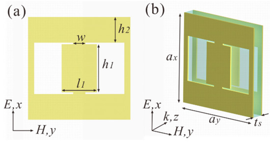
Figure 1.
(a) Scheme of left-handed metamaterials’ (LHMs) unit cell from (a) front and (b) perspective views. In which, w = 7.6 μm, l1 = 22 μm, h1 = 30 μm, h2 = 16 μm, ax = ay = 64 μm, and ts = 5 μm.
3. Simulation and Results
Typically, the effective refractive index n, impedance z, permittivity ε and permeability μ of the LHMs can be calculated by using the S parameter retrieval method [17,29,30]. In specific, the n can be written as:
with r = (z − 1)/(z + 1) and . Then, the permittivity and permeability can be obtained by:
In the above equations, k0 is the vacuum wave vector, d is the effective medium thickness, and m is the integer number. S11 and S21 are the reflection coefficient and transmission coefficient, respectively.
To investigate n, ε and μ, S11 and S21 should be firstly offered. Here, they are provided by performing CST microwave studio. For TM, THz wave (the electric field parallel to the x-axis) incident along the z-axis on the single-layer LHMs structure, S21 is shown in Figure 2a, in which the peaks transmission coefficients of −8.94 dB and −10.73 dB appear near 2.35 THz and 3.06 THz, respectively. Subsequently, the effective refractive index n, permittivity ε and permeability μ are calculated according to Equations (1) and (2) and demonstrated in Figure 2b–d, respectively. Figure 2c shows that the real part of ε is negative in whole 2.0–3.4 THz, while Figure 2d shows that the real part of μ is negative in frequency ranges of 2.336–2.448 THz and 3.041–3.108 THz. That is, ε < 0 and μ < 0 are simultaneously satisfied in two frequency ranges, resulting in the dual-band’s negative refraction of LHMs in Figure 2b. We note that in the calculation, m in Equation (1) is taken as 0 due to the thickness of single-layer LHMs is far less than incident wavelength [17,29,30].
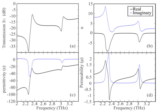
Figure 2.
The (a) transmission coefficient S21, (b) effective refraction index n, (c) permittivity ε and (d) permeability μ of single-layer LHMs. In (b,c), the real and imaginary parts are depicted by solid and dashed curves, respectively.
The physical mechanism can be explained by the external magnetic field of incidence that produces LC oscillation and forms a loop current in LHMs, and then the magnetic dipole is excited, and negative permeability is provided. Those principles can be demonstrated from the distributions of surface currents and the electric and magnetic fields shown in Figure 3. Specifically, the first peak of transmission coefficient in Figure 2a appears at 2.35 THz, and the surface current distributions for LHMs in Figure 1b at the inner (facing each other) metallic surfaces of the front and back slabs are shown in Figure 3(ai,aii), respectively. From Figure 3(ai,aii), we can know the surface current on the h2 regions is anti-paralleled to that on the h1 regions. Furthermore, the surface currents on the front slab (Figure 3(ai)) is opposite to those on the back (Figure 3(aii)). Thus, the surface currents form an equivalent current loop, which can be regarded as a magnetic dipole and exhibits magnetic resonance under the incident wave. To verify the surface current distributions, Ez and Hy fields at the xy-plane, which is located in the middle dielectric between the front and back metal slabs, are separately demonstrated in Figure 3(aiii,aiv). We can see that Ez and Hy distributions are both consistent with the current distributions shown in Figure 3(ai,aii). As we know, the permittivity of the metamaterial can be theoretically expressed as where γ and ωp are plasma dissipation and frequency, respectively. The permeability is with . Here, ωm is the magnetic resonance frequency; L, C and Γ are loop inductance, capacitance of magnetic resonance region, and LC loss factor, respectively; F is the volume factor. For our proposed fishnet structure, ωp is determined by geometry parameters, which have been specially set as in Figure 1a, providing negative permittivity (Figure 2c). ωm is related to LC resonances demonstrated by the formation of current loops in Figure 3(ai,aii), and the induced Hy of h2 region in (iv) is opposite to that of incidence, implying negative permeability.
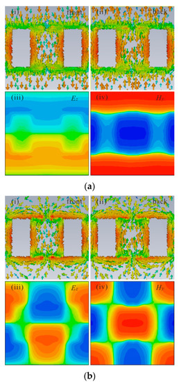
Figure 3.
Surface current distributions on the (i) front and (ii) back metal slabs, and field distributions (iii) Ez and (iv) Hy at xy-plane located in the middle dielectric between the front and back metal slabs of LHMs’ unit cell for (a) 2.35 terahertz (THz) and (b) 3.06 THz.
For the second peak of transmission coefficient in Figure 2a, which appears at 3.06 THz, the front/back surface current distributions, Ez and Hy, is demonstrated in Figure 3(bi–biv). Similar to the results of 2.35 THz of Figure 3a, the current loop and magnetic resonance can be offered. However, the details of the distributions in Figure 3b are different than those in Figure 3a, and the surface currents on the h1 regions and the corners of the h2 regions are anti-paralleled to those on the other regions, indicating different LHMs occurrence.
4. Discussion
The existence of negative refraction is validated by the electric field of a stacked LHMs prism. As shown in Figure 4, the stacked LHMs consist of multiplying single-layer LHMs with the period (p = 6 μm) along the z-direction, and 13 layers of single-layer LHMs gradually decreasing to 7 layers, from the left to right side, is set to form prism with an angle of 1.79°. A 2.37 THz wave (the electric field along x-direction) is a normal incident from the bottom, and the Ex distribution is shown in Figure 4a. Figure 4b is the local area in a magnified view of Figure 4a. From Figure 4b, we can see that the negative refraction with an angle of α1 = −3.37° is provided. The effective refractive index n of the LHMs’ prism can be deduced from relations of incidence and refraction angles by Snell’s law, here n = −2.08. In the same way, the effective refractive indices for 2.04–2.42 THz are calculated and demonstrated in Figure 4c (blue line), which show that negative refraction can be realized in this frequency band. Similarly, the electric field distribution for 3.17 THz is illustrated in Figure 5a,b, in which angle of α2 = −3.21° and effective refractive index n = −1.79 are provided. Meanwhile, the effective refractive indices for 3.12–3.28 THz are shown in Figure 5c (blue line), indicating the second negative refraction band. Comparing to the dual bands of single-layer LHMs at 2.336–2.448 THz and 3.041–3.108 THz, the bands of stacked LHMs vary to 2.04–2.42 THz and 3.12–3.28 THz. The shift and expanding of bands in stacked LHMs are mainly due to the strong coupling between adjacent layers of single-layer LHMs, which results in plasmonic hybridization [16].
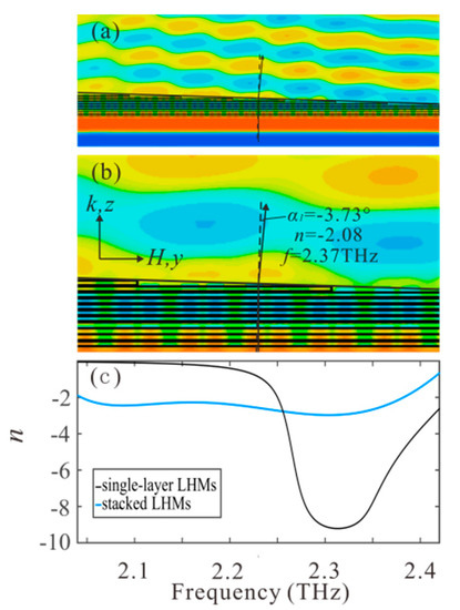
Figure 4.
(a) Ex distribution and (b) the local area in a magnified view for a 2.37 THz normal incident wave (the electric field along the x-direction) from the bottom. (c) The calculated refractive indices of stacked LHMs (blue line) and single-layer LHMs (black line).
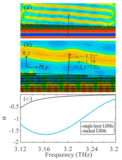
Figure 5.
(a) Ex distribution and (b) the local area magnified view for a 3.17 THz normal incident wave (the electric field along the x-direction) from the bottom. (c) The calculated refractive indices of stacked LHMs (blue line) and single-layer LHMs (black line).
5. Conclusions
THz LHMs constructed by plasmonic fishnet structures are designed. Calculated permittivity ε and permeability μ of single-layer LHMs show that ε < 0 and μ < 0 can be simultaneously achieved in 2.336–2.448 THz and 3.041–3.108 THz ranges, realizing dual-band LHMs. The distribution of surface current and the electric and magnetic fields at 2.35 THz and 3.06 THz verify the prediction. Moreover, the existence of negative refraction is validated by the electric field of stacked LHMs’ prism. It shows that in 2.04–2.42 THz and 3.12–3.28 THz, negative refractive indices of the prism can be obtained. The results facilitate LHMs’ practical application in THz image, sensor, detection, communication, and so on.
Author Contributions
Conceptualization, S.Z. and Y.S.; methodology, Z.W. and L.X.; software, Z.W.; validation, S.O., J.X. and L.X.; formal analysis, Y.S. and Z.W.; investigation, Z.W.; resources, Y.S.; data curation, Z.W.; writing—original draft preparation, Z.W.; writing—review and editing, S.Z. and Y.S.; funding acquisition, Y.S. All authors have read and agreed to the published version of the manuscript.
Funding
This work was supported by the National Natural Science Foundation of China (Grant numbers 61865009, 61927813).
Data Availability Statement
Data are available from the authors on request.
Conflicts of Interest
The authors declare no conflict of interest.
References
- Veselago, V.G. The electrodynamics of substances with simultaneously negative values of ε and μ. Sov. Phys. Usp. 1968, 10, 509–514. [Google Scholar] [CrossRef]
- Smith, D.R.; Padilla, W.J.; Vier, D.C.; Nemat-Nasser, S.C.; Schultz, S. Composite medium with simultaneously negative permeability and permittivity. Phys. Rev. Lett. 2000, 84, 4184–4187. [Google Scholar] [CrossRef]
- Cao, M.; Wang, X.; Zhang, M.; Shu, J.; Cao, W.; Yang, H.; Fang, X.; Yuan, J. Electromagnetic response and energy conversion for functions and devices in low-dimensional materials. Adv. Funct. Mater. 2019, 29, 1807398. [Google Scholar] [CrossRef]
- Cao, M.; Shu, J.; Wang, X.X.; Wang, X.; Zhang, M.; Yang, H.; Fang, X.; Yuan, J. Electronic structure and electromagnetic properties for 2D electromagnetic functional materials in gigahertz frequency. Ann. Phys. 2019, 531, 1800390. [Google Scholar] [CrossRef]
- Pendry, J.B.; Holden, A.J.; Stewart, W.J.; Youngs, I. Extremely low frequency plasmons in metallic mesostructures. Phys. Rev. Lett. 1996, 76, 4773–4776. [Google Scholar] [CrossRef] [PubMed]
- Pendry, J.B.; Holden, A.J.; Robbins, D.J.; Stewart, W.J. Low frequency plasmons in thin-wire structures. J. Phys. Conds. Matter 1998, 10, 4785–4809. [Google Scholar] [CrossRef]
- Smith, D.R.; Schultz, S.; Markoš, P.; Soukoulis, C.M. Determination of effective permittivity and permeability of metamaterials from reflection and transmission coefficients. Phys. Rev. B 2002, 65, 195104. [Google Scholar] [CrossRef]
- Rizwan, M.; Mahmood, T.; Rafique, H.M.; Tanveer, M.; Haider, S.F. Design of a negative refractive index material based on numerical simulation. Chin. J. Phys. 2016, 54, 587–591. [Google Scholar] [CrossRef]
- Jia, X.; Wang, X. Optical fifishnet metamaterial with negative, zero, positive refractive index and nearly perfect absorption behavior at difffferent frequencies. Optik 2019, 182, 464–468. [Google Scholar] [CrossRef]
- Askari, M.; Niakan, N.; Zakery, A. A high transmission and low loss metamaterial with negative refraction at 458 THz. Optik 2013, 124, 2210–2213. [Google Scholar] [CrossRef]
- Chen, H.; Ran, L.; Huangfu, J.; Zhang, X.; Chen, K. Left-handed materials composed of only S-shaped resonators. Phys. Rev. E 2004, 70, 057605. [Google Scholar] [CrossRef] [PubMed]
- Baena, J.D.; Marqués, R.; Medina, F.; Martel, J. Artificial magnetic metamaterial design by using spiral resonators. Phys. Rev. B 2004, 69, 014402. [Google Scholar] [CrossRef]
- Askari, M.; Zakery, A.; Jahromi, A.S. A low loss semi H-shaped negative refractive index metamaterial at 4.725 THz. Photonics Nanostruct. 2018, 30, 78–83. [Google Scholar] [CrossRef]
- Li, W.; Meng, Q.; Huang, R.; Zhong, Z.; Zhang, B. Thermally tunable broadband terahertz metamaterials with negative refractive index. Opt. Commun. 2018, 412, 85–89. [Google Scholar] [CrossRef]
- Bejide, M.; Li, Y.; Stavrias, N.; Redlich, B.; Tanaka, T.; Lam, V.D.; Nguyen, T.T.; Janssens, E. Transient transmission of THz metamaterial antennas by impact ionization in a silicon substrate. Opt. Express 2021, 29, 170–181. [Google Scholar] [CrossRef]
- Nguyen, T.H.; Le, D.H.; Bui, S.T.; Bui, X.K.; Nguyen, X.C.; Vu, D.L. Plasmonic hybridization in symmetric metamaterial for broadband negative refractive index: Simulation, experiment and characterization. J. Phys. D Appl. Phys. 2020, 53, 175501. [Google Scholar] [CrossRef]
- Zhao, G.; Bi, S. Design and verification of double band negative refraction metamaterial. Phys. Lett. 2019, 725, 92–96. [Google Scholar] [CrossRef]
- Hossain, M.J.; Faruque, M.R.I.; Islam, M.T. Design and analysis of a new composite double negative metamaterial for multi-band communication. Curr. Appl. Phys. 2017, 17, 931–939. [Google Scholar] [CrossRef]
- Kowerdziej, R.; Jaroszewicz, L. Active control of terahertz radiation using a metamaterial loaded with a nematic liquid crystal. Liq. Cryst. 2016, 43, 1120–1125. [Google Scholar] [CrossRef]
- Islam, M.T.; Hoque, A.; Almutairi, A.F.; Amin, N. Left-handed metamaterial-inspired unit cell for S-Band glucose sensing application. Sensors 2019, 19, 169. [Google Scholar] [CrossRef] [PubMed]
- Khalid, N.; Abbasi, N.A.; Akan, O.B. Statistical characterization and analysis of low-THz communication channel for 5G Internet of Things. Nano Commun. Netw. 2019, 22, 100258. [Google Scholar] [CrossRef]
- Mishra, C.S.; Nayyar, A.; Suseendran, G.; Palai, G. L-Shape Si-waveguide for THz-Communication. Optik 2019, 178, 509–512. [Google Scholar] [CrossRef]
- Bai, P.; Zhang, Y.; Wang, T.; Fu, Z.; Shao, D.; Li, Z.; Wan, W.; Li, H.; Cao, J.; Guo, X.; et al. Broadband THz to NIR up-converter for photontype THz imaging. Nat. Commun. 2019, 10, 1–9. [Google Scholar] [CrossRef]
- Hernandez-Cardoso, G.G.; Rojas-Landeros, S.C.; Alfaro-Gomez, M.; Hernandez-Serrano, A.I.; Salas-Gutierrez, I.; Lemus-Bedolla, E.; Castillo-Guzman, A.R.; Lopez-Lemus, H.L.; Castro-Camus, E. Terahertz imaging for early screening of diabetic foot syndrome: A proof of concept. Sci. Rep. 2017, 7, 42124. [Google Scholar] [CrossRef]
- Gui, S.; Li, J.; Pi, Y. Security imaging for multi-target screening based on adaptive scene segmentation with Terahertz Radar. IEEE Sens. J. 2018, 19, 2675–2684. [Google Scholar] [CrossRef]
- Gómez-Castaño, M.; Garcia-Pomar, J.L.; Pérez, L.A.; Shanmugathasan, S.; Ravaine, S.; Mihi, A. Electrodeposited Negative Index Metamaterials with Visible and Near Infrared Response. Adv. Opt. Mater. 2020, 8, 2000865. [Google Scholar] [CrossRef]
- Xiao, Y.; Norouzian, F.; Hoare, E.G.; Marchetti, E.; Gashinova, M.; Cherniakov, M. Modelling and experiment verification of transmissivity of low-THz radar signal through vehicle infrastructure. IEEE Sens. J. 2020, 20, 8483–8496. [Google Scholar] [CrossRef]
- Kafesaki, M.; Tsiapa, I.; Katsarakis, N.; Koschny, T.; Soukoulis, C.M.; Economou, E.N. Left-handed metamaterials: The fishnet structure and its variations. Phys. Rev. B 2007, 75, 235114. [Google Scholar] [CrossRef]
- Chen, X.; Grzegorczyk, T.M.; Wu, B.I.; Pacheco, J.; Kong, J.A. Robust method to retrieve the constitutive effective parameters of metamaterials. Phys. Rev. E 2004, 70, 016608. [Google Scholar] [CrossRef] [PubMed]
- Hou, Z.L.; Zhang, M.; Kong, L.B.; Fang, H.M.; Li, Z.J.; Zhou, H.F.; Jin, H.B.; Cao, M.S. Microwave permittivity and permeability experiments in high-loss dielectrics: Caution with implicit Fabry-Pérot resonance for negative imaginary permeability. Appl. Phys. Lett. 2013, 103, 162905. [Google Scholar] [CrossRef]
Publisher’s Note: MDPI stays neutral with regard to jurisdictional claims in published maps and institutional affiliations. |
© 2021 by the authors. Licensee MDPI, Basel, Switzerland. This article is an open access article distributed under the terms and conditions of the Creative Commons Attribution (CC BY) license (https://creativecommons.org/licenses/by/4.0/).