Abstract
The integrated III-V self-injection locked (SIL) laser exhibits excellent linewidth compression, noise reduction, and frequency stability. However, the laser’s low efficiency and fluctuating output power severely limit its applications in optical coherent transmission, light detection and ranging (LiDAR), spectroscopy, and so on. Based on the rate equations for a semiconductor laser coupled to counter-propagating fields in a micro-ring resonator (MRR), we systematically investigate the laser power and linewidth compression under self-locking conditions. We improve the slope efficiency by adjusting the injection phase, diode–MRR coupling efficiency, the normalized mode-coupling rate between clockwise (CW) and counter-clockwise (CCW) modes, and the MRR Q-factor. The results show that the enhanced diode–MRR coupling efficiency effectively increases the laser slope efficiency and improves the stability of the injection phase and feedback intensity. The injection phase significantly influences the range of the self-injection locked state. The normalized mode-coupling rate effectively affects the locking bandwidth and maintains stable power transfer. The MRR intrinsic Q-factor has a positive correlation with improving the laser slope efficiency and compressing the linewidth.
1. Introduction
Narrow-linewidth and high-efficiency lasers are attractive for use in optical coherent communications, sensing and metrology, and light detection and ranging (LiDAR) [1,2,3,4]. The integrated III-V self-injection locked (SIL) laser may provide a relatively easy and cost-effective way to produce a stable laser source with low phase/frequency noise and narrow linewidth [5,6,7,8]. Meanwhile, the integrated SIL lasers using low-loss micro-ring resonator (MRR) external cavities have been highly praised for providing wavelength-selective external feedback. Various impressive integrated SIL lasers, including ultralow narrow-linewidth and widely tunable ranges, have been demonstrated [6,7,8,9,10]. The stabilization of a laser emission frequency via resonant optical feedback depends on the feedback intensity into the diode cavity and injection phase. Most of the feedback intensity relies on Rayleigh scattering in the micro-ring, which is typically low and susceptible to fabrication technology. To achieve optimal feedback intensity in a self-injection locking system, an adjustable Sagnac loop reflector coupled to a high-Q MRR is introduced by Su [11]. To let the SIL scheme function well at high powers, the unified laser stabilization structure is proposed by White [8]. Lang analyzed the asymmetric tuning curve and dynamic instability in SIL characteristics. The instability originates from the intermode interaction via the modulation in the injected carrier density caused by intensity beat [12]. Asghar achieved a minimum RF linewidth of 1 kHz on the optimum wavelengths (1571.21 to 1572.71 nm) using simultaneous optical injection and optical feedback [13].
One of the key metrics for an integrated SIL laser is its slope efficiency. By far, there have been several papers reporting or discussing the output power or the efficiency of integrated III-V SIL lasers [11,14,15,16,17]. Li measured the output power from the drop port of a DFB laser locked to a 1.41 m long, ultrahigh Q-factor Si3N4 (SiN) integrated resonator and perceived that the output power does not increase monotonically with the DFB driving current [15]. Su measured the output power of the SIL laser under different reflectivity by way of an adjustable Sagnac loop reflector [11]. Xiang gave the light–current measurement of the DFB laser locked to thermally tunable SiN ultrahigh-Q resonators [16]. Siddharth reported up to 10.5 mW output power of an integrated extended distributed Bragg reflector (E-DBR) laser in the self-injection locked range [17]. However, research on the characteristics of slope efficiency in SIL lasers based on MRRs is limited. This work discusses the factors affecting on-chip high output power and stability in SIL lasers. Based on the MRR external cavity design approach presented here, power and linewidth can be balanced for different application scenarios.
In this manuscript, we aim to strike a balance between output power and linewidth reduction in diode lasers locked to high-Q micro-ring resonators. We incorporate the laser rate equations with the coupled-mode equations for the clockwise or forward optical field (which is the mode directly pumped by the laser field) and the counter-clockwise or backscattered field in the MRR to numerically analyze the self-injection locking dynamics [18,19,20,21,22,23]. Focus is given to the slope efficiency of this SIL laser, with emphasis on the key parameters: injection phase, diode–MRR coupling efficiency, the normalized mode-coupling rate between clockwise (CW) and counter-clockwise (CCW) modes, the MRR Q-factor, and the SOA intrinsic loss. Theoretical analysis and numerical simulations identify the diode–MRR coupling efficiency as a dominant factor governing SIL laser slope efficiency, which disturbs the feedback intensity and injection phase of the external cavity return diode. A 3 dB reduction in coupling efficiency could lead to nearly 50% decrease in laser output power. Increasing the normalized mode-coupling rate effectively broadens the locking bandwidth and improves the slope efficiency. Notably, a change in the injection phase by π/2 has a moderate effect on slope efficiency but significantly shifts the locking range. Furthermore, slope efficiency can be improved by increasing the MRR Q-factor, but the high normalized delay may cause system instability. These findings open up the door for the development of high-power SIL laser sources for high-order orthogonal amplitude modulation (QAM) systems, high-resolution optical sensing, and other applications.
2. Theory and Design
A simplified sketch of the SIL laser consisting of a laser diode (LD) and an external MRR can be described in Figure 1. Re and R0 are the reflectivity of the back facet and front facet of the single-mode LD, respectively. The optical power produced by the normalized mode-coupling rate between CW and CCW modes β is reflected back into the LD, locking the laser to the resonate frequency of the external MRR. As a result, the lasing frequency of the LD is narrowed and stabilized.
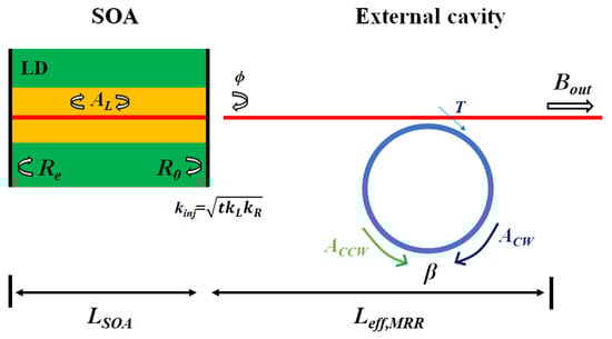
Figure 1.
Sketch of the SIL laser considered in this paper. Bin is the amplitude coupled to the MRR; Bt is the amplitude transmitted at the output port; AL is the circulating field inside the laser cavity; ACW and ACCW are the amplitudes of the clockwise and counter-clockwise transmission modes in the micro-ring resonator. T is the amplitude transmittance coefficient of the micro-ring coupler.
The SIL laser system dynamics could be described by conventional laser rate equations with the coupled terms [10]:
where N is the carrier density, V is the laser active volume, a is the differential gain, τe is the carrier lifetime, and γ = 1/τe is the carrier recombination rate. The threshold current, Ith = γN0eV, is determined by the transparent carrier density N0. αH is the linewidth enhancement factor, is the current frequency tuning coefficient, and k = αic/nSOA is the SOA laser cavity loss rate, which can be converted to the intrinsic loss coefficient αi. is the diode–MRR coupling efficiency, where is the energy coupling efficiency between the facets of the laser and the micro-resonator waveguide. and denote the external coupling rate of the laser facet and the micro-resonator, respectively. The MRR group index can be obtained using the ng = λ2/(FSR × LMRR), where LMRR is the round-trip length of the aluminum nitride MRR. and are the MRR loss and coupling rates, respectively. AL is the laser field, is the injection phase, including the propagation delay phase and the refractive index changes due to the Henry factor, and is the detuning of the generation frequency from the MRR resonance . FA is the Langevin noise term to describe the spontaneous emission into the lasing field [24]. ACW and ACCW are the CW and the CCW optical fields in the MRR, respectively. The CCW wave ACCW is injected back into the laser, with an injection phase shift and a coupling rate between the micro-resonator mode and the laser mode that is denoted by . is the normalized mode-coupling rate between CW and CCW modes [23], Bout is the output power, and T is the amplitude transmittance coefficient of the MRR coupler.
It is convenient to use the normalized tuning curve to analyze the self-injection locking range, which shows the dependence of the effective frequency detuning ζ = (ω − ωm)/km on the detuning of the laser cavity frequency ωL from the micro-ring resonator eigenfrequency ξ = (ωL − ωm)/km, where km = ki + kp. The normalized tuning curve can be described by the following formula [7]:
where K = is the SIL stable coefficient. The detailed definitions and values of the parameters used in the simulations are presented in Table 1.

Table 1.
Values and definitions of parameters used in simulations.
3. Lasing Behavior with Varying Chip Current
We modeled and simulated Equations (1)–(4) to obtain the output power of the SIL laser. Using the simulation data, we computed the laser frequency noise power spectral density (PSD) and derived the locked intrinsic linewidth to characterize the laser linewidth narrowing effect [25]. Figure 2 illustrates the simulation results obtained when the laser bias current is forward-swept across a range of 240 mA. The backward-swept results are slightly different due to hysteresis induced by the phase matching criterion and mode coupling effects. During the forward and backward scanning of the current, the asymmetry in the rise and fall rates of the carrier density in the diode results in varying rates of change in both the refractive index and the phase. mode-coupling causes the losses of other longitudinal modes to exceed those of the primary lasing mode, thereby suppressing mode hopping. The threshold currents of the free-running laser and the self-injection-locked laser are 35 mA and 30 mA, respectively. This difference is attributed to the gain threshold variation caused by the local refractive index difference in the active region of the laser diode [26,27]. Additionally, the increase in feedback intensity during the injection phase (ϕ = 0) can further reduce the threshold current in the locked state. The self-injection locking phenomenon was observed around three distinct injection currents: 102 mA, 156 mA, and 208 mA. This multiple-current locking effect could primarily be attributed to the current frequency tuning in the laser diode and the presence of multiple resonance peaks in the external MRR due to the free spectral range. In the contiguous locked states, the lasing wavelength shift induced by variations in the injection current is precisely an integer multiple of the free spectral range of the MRR. When the laser diode’s emission frequency is significantly detuned from the MRR’s eigenfrequencies, it experiences negligible optical feedback from the MRR and operates in a free-running mode, with its frequency and power varying linearly. As the emission frequency approaches a resonance of the MRR, an increasing fraction of light becomes resonantly enhanced within the micro-resonator, reflected, and reinjected into the laser diode, resulting in SIL. The power drop in the locked state is due to the intensity filtering effect of the MRR’s FSR [16]. Under weak feedback conditions, increasing the feedback intensity can enhance the power in the locked state, while optimizing the injection phase enables a stable locked state and an extended tuning range [18]. Additionally, frequency fluctuations caused by variations in the injection current are significantly suppressed.
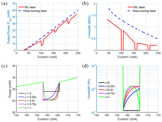
Figure 2.
(a,b) Simulated SIL laser LIV and linewidth curves with diode current forward tuning (ϕ = 0.25π, β = 0.3, kinj = 0.5, Q = 106, αi = 20 cm−1). (c,d) Simulated output power and linewidth in SIL states across one MRR resonance with different injection phase ϕ (β = 0.3, kinj = 0.5, Q = 106, αi = 20 cm−1).
In the SIL regime, the output power exhibits abrupt decreases, as shown in Figure 2a. These features significantly differ from the Lorentzian resonance shape that would be observed without SIL [25], and all features have different shapes due to the varying injection phase. As shown by the black and orange solid lines in Figure 2c,d, a change in π in the injection phase causes the maximum output power to decrease from 33 mW to 25 mW, while the linewidth increases almost tenfold. Meanwhile, the frequency fluctuation caused by injection current variations is notably suppressed, as shown in Figure 2b,d.
Figure 3a,b depict the relationship between the SIL laser output power and the normalized mode-coupling coefficient between clockwise and counter-clockwise modes in the external MRR. Increasing the normalized mode-coupling coefficient from 0.1 (orange solid line) to 0.5 (black solid line) results in a slow increase in the output power from 31 to 36 mW, with the benefit of the linewidth reduction and the locking bandwidth’s increases. As shown in Figure 3c,d, as the diode–MRR coupling efficiency decreases from 0.9 (black solid line) to 0.1 (orange solid line), the output power drops rapidly by 11 mW, and the linewidth broadens. This is the primary factor influencing slope efficiency, as fluctuations in coupling efficiency can lead to significant deviations in the injection phase and the effective feedback strength reflected back into the diode cavity. This, in turn, can cause the system to lose its stable locking state. In addition, the increased diode intrinsic loss of 40 cm−1 will also lead to an 8 mW decrease in output power and the increase in the linewidth, as shown by the black and orange solid lines in Figure 3e,f. In reality, both the diode–MRR coupling loss and the diode intrinsic loss contribute to a portion of the overall laser cavity loss. The increase in losses will inevitably lead to a decrease in the output power and an increase in the linewidth.
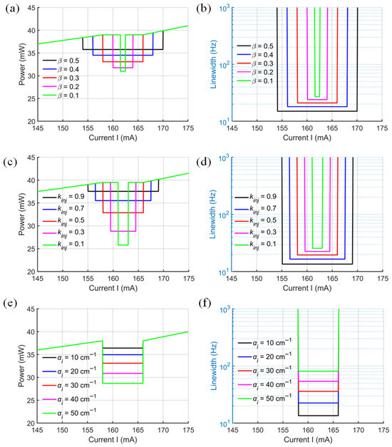
Figure 3.
(a,b) Output power and linewidth in SIL states across one MRR resonance with different normalized mode-coupling rate β (ϕ = 0, kinj = 0.5, Q = 106, αi = 20 cm−1). (c,d) Output power and linewidth in SIL states across one MRR resonance with different diode–MRR coupling efficiency kinj (ϕ = 0, β = 0.3, Q = 106, αi = 20 cm−1). (e,f) Output power and linewidth in SIL states across one MRR resonance with different SOA intrinsic loss αi (ϕ = 0, β = 0.3, Q = 106, kinj = 0.5).
In summary, the output power in the locked state is jointly influenced by the injection phase, the normalized mode-coupling coefficient, the chip–facet coupling efficiency, and the intrinsic laser loss. With a fixed coupling efficiency, the normalized mode-coupling coefficient and injection phase emerge as the most critical parameters. A phase variation in π results in a reduction in the maximum output power from 33 mW to 25 mW, while increasing the normalized coupling coefficient by 0.4 enhances the output power by approximately 5 mW. Maximizing the coupling efficiency and minimizing intrinsic laser loss are also consistently beneficial for achieving high output power.
4. Lasing Behavior with Varying External Cavity Characteristics
In this section, we study how self-injection locking depends on significant parameters of the external cavity: the normalized mode-coupling rate, injection phase, diode–MRR coupling efficiency, and MRR Q-factor.
Figure 4 illustrates how the locking range, slope efficiency, linewidth, and PSD vary as the normalized mode-coupling coefficient β increases from 0 to 1 [28]. The injection phase ϕ is fixed at 0, the SOA intrinsic loss αi is set to 20 cm−1, the coupling efficiency kinj is 0.5, and the MRR Q-factor is 106. At β = 0, there is no optical feedback or self-injection locking, and the MRR functions as an external filter with additional diode–MRR coupling loss. As β increases, the locking range expands, while the slope efficiency increases monotonically and slowly. At β = 0.25, a fluctuation of 0.02 mW/mA occurs in the slope efficiency when the detuning frequency is increased from 0 to 5 GHz. The solid green line in Figure 4a,b shows that the slope efficiency can increase to 0.6 mW/mA at β = 1, with a locking range of 36 GHz. As illustrated in Figure 4c,d, increasing the normalized mode-coupling rate reduces the SIL laser linewidth, which aligns with previously reported experimental findings [11]. Increasing the reflectivity of the weak feedback from 0 to 0.32 reduced the intrinsic linewidth by a factor of six. Although the reduction occurs monotonically, the resulting linewidths remain within the same order of magnitude.
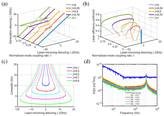
Figure 4.
Effect of normalized mode-coupling rate on (a) normalized generated frequency, (b) laser slope efficiency, (c) laser linewidth, and (d) frequency noise power spectral density. (ϕ = 0, kinj = 0.5, Q = 106, αi = 20 cm−1).
The phase-dependent characteristics of the SIL laser system are quantitatively analyzed in Figure 5, which presents the evolution of four critical performance parameters (locking range, slope efficiency, spectral linewidth, and PSD) as functions of the injection phase ϕ. The normalized mode-coupling coefficient β is fixed at 0.5, the SOA intrinsic loss αi is set to 20 cm−1, the coupling efficiency kinj is maintained at 0.5, and the MRR Q-factor is 106. Figure 5a tells us that the injection phase does not significantly affect the locking range. Likewise, the maximum value of the slope efficiency remains nearly constant for a given injection phase. However, the laser–microring detuning range required to achieve the maximum slope efficiency varies considerably with different injection phases. For ϕ = 0.5π and π, both the slope efficiency and the linewidth exhibit significant dependence on the laser–microring detuning, as shown by the red and orange solid lines in Figure 5b. The slope efficiency at the optimal injection phase, corresponding to ϕ = 0 (blue solid line), reaches 0.58 mW/mA, with a locking range of 20 GHz. Notably, when the slope efficiency reaches its peak, the linewidth achieves its minimum value. In practical experiments, the laser–microring detuning range is critical in determining whether the device can simultaneously achieve high slope efficiency and narrow linewidth. Reference [18] also emphasizes that SIL stabilization can be optimized under the optimal injection phase. A phase shift of 0.5π reduces the power at the central detuning frequency by nearly half. Consequently, optimizing the injection phase to maximize the detuning range for achieving high slope efficiency and narrow linewidth is essential for designing an efficient SIL laser.
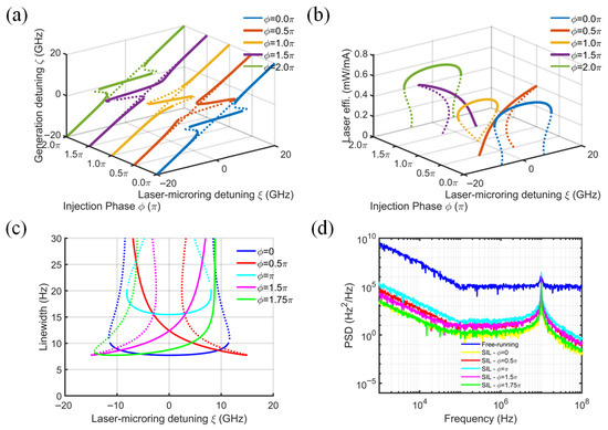
Figure 5.
Effect of injection phase on (a) normalized generated frequency, (b) laser slope efficiency, (c) laser linewidth, and (d) frequency noise power spectral density. (β = 0.5, kinj = 0.5, Q = 106, αi = 20 cm−1).
Importantly, the injection phase is related to both the initial phase and the feedback round-trip time. The normalized delay is defined as the product of the external cavity round-trip time τs and the MRR’s mode decay rate (km = ki + kp). The injection phase is periodic and mainly determines the position of the locking curve, while the normalized delay changes locking frequency. A low Q-value (large κm) significantly tightens the constraint on the external cavity delay τs, making the system more susceptible to delay-induced multi-stability. As shown in Figure 6a,b, when κmτs ≪ 1, a single stable locked state can be obtained. When κmτs ≥ 1, multiple extrema appear within the resonance envelope, and the system enters a multi-stable state. Therefore, increasing the resonator Q-value, rather than simply increasing the micro-ring cavity length, is crucial for suppressing oscillations and multi-stabilities caused by long cavity lengths or high external cavity round-trip times. On AlN platforms, designing MRRs with Q-values of 106–108 is beneficial for enhancing system stability.
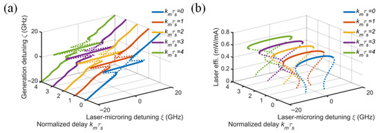
Figure 6.
Effect of normalized delay on (a) normalized generated frequency and (b) laser slope efficiency (β = 0.5, ϕ = 0, kinj = 0.5, Q = 106, αi = 20 cm−1).
Figure 7 demonstrates the systematic dependence of SIL laser characteristics, including locking range, slope efficiency, linewidth, and PSD, on diode–MRR coupling efficiency kinj. The normalized mode-coupling coefficient β and the injection phase ϕ are fixed at 0.5 and 0, respectively, the SOA intrinsic loss αi is 20 cm−1, and the MRR Q-factor is 106. Figure 7a,b manifest that a low diode–MRR coupling efficiency results in not only poor output power but also a narrow locking range and the deterioration of the spectral properties. As kinj increases, the slope efficiency increases, while the linewidth decreases monotonically, which is consistent with the results reported in reference [29]. At kinj = 0.5, the slope efficiency decreases by only 0.02 mW/mA when the detuning frequency increases from 0 to 10 GHz. At kinj = 0.9 (green solid line), the slope efficiency reaches 0.75 mW/mA, and the locking range reaches 38 GHz. In fact, the diode–MRR coupling loss is a part of the loss within the cavity of a SIL laser. The greater the loss, the lower the slope efficiency and the larger the linewidth. In addition, the injection phase and feedback intensity will also be unstable due to the fluctuation of coupling loss and may cause the slope efficiency of the SIL laser to be lower than that of the free-running laser. Therefore, a high diode–MRR coupling efficiency is what is expected of the SIL laser. There are various waveguide tapers for reducing diode–MRR coupling loss in reported SIL lasers [30].
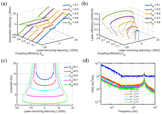
Figure 7.
Effect of diode–MRR coupling efficiency on (a) normalized generated frequency, (b) laser slope efficiency, (c) laser linewidth, and (d) frequency noise power spectral density. (ϕ = 0, β = 0.5, Q = 106, αi = 20 cm−1).
The impact of MRR Q-factor variation (105–109) on SIL laser performance is revealed in Figure 8, which depicts the variation in locking range, slope efficiency, linewidth, and PSD. The normalized mode-coupling rate β and the injection phase ϕ are set to 0.5 and 0, respectively. The SOA intrinsic loss αi is 20 cm−1, and the coupling efficiency kinj is 0.5. Note that as β is proportional to the MRR Q-factor, the locking band is effectively proportional to the ratio of the MRR to laser cavity quality factors, as demonstrated in Ref. [23]. A micro-ring external cavity with a Q-factor of 106–107 (red and orange solid lines) can be selected to achieve a slope efficiency of about 0.55 mW/mA and a locking range of ±10 GHz. A high Q-factor provides a longer effective optical length and narrow feedback light linewidth, which is conducive to achieving linewidth compression and frequency stabilization of the laser, as shown in Figure 8c,d.
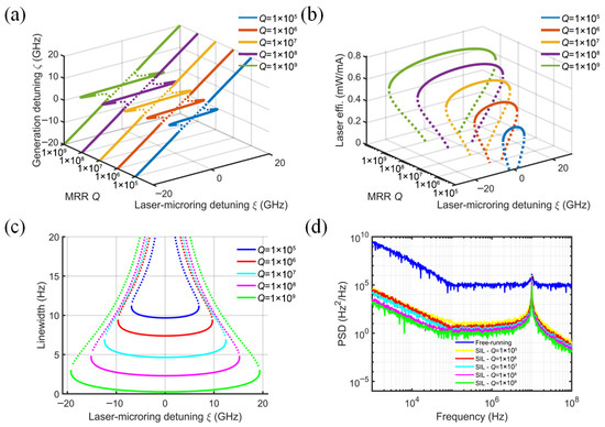
Figure 8.
Effect of MRR Q-factor on (a) normalized generated frequency, (b) laser slope efficiency, (c) laser linewidth, and (d) frequency noise power spectral density. (ϕ = 0, β = 0.5, kinj = 0.5, αi = 20 cm−1).
In summary, the dynamics of SIL lasers is systematically investigated by combining rate equations and MRR coupled-mode equations that model the normalized mode-coupling rate, injection phase, diode–MRR coupling efficiency, MRR Q-factor, and the intrinsic loss of the SOA. These factors influence the laser’s slope efficiency and linewidth. Simulation results indicate that improving the diode–MRR coupling efficiency is critical for achieving high output power in integrated SIL lasers, as it directly affects both the injection phase and the normalized mode-coupling coefficient. Tuning the injection phase to 2π is favorable for maintaining a stable locking state, while increasing the normalized mode-coupling coefficient under weak feedback conditions broadens the locking bandwidth and enhances slope efficiency. Additionally, a high-Q MRR and a low-intrinsic-loss SOA consistently contribute to linewidth narrowing. Notably, MRRs with high Q-factors (106–108) exhibit increased tolerance to multi-stability induced by high normalized delay associated with long external cavity round-trip times.
5. Discussion
In Table 2, we summarize the performance improvements of the SIL laser under various optimized parameters. We emphasize that the diode–MRR coupling efficiency plays a crucial role, as its fluctuations directly affect both the injection phase and feedback intensity. Increasing the coupling efficiency kinj from 0.1 to 0.9 results in a 35 GHz increase in locking bandwidth, a 0.4 mW/mA improvement in slope efficiency, and a sixfold reduction in linewidth. Therefore, ensuring low-loss coupling and packaging is essential for engineering high-power, stable SIL lasers. In the weak-feedback regime (β < 1), increasing the normalized coupling coefficient β and the external cavity Q-factor enhances slope efficiency and enables linewidth compression. Specifically, increasing β from 0 to 0.9 yields a 38 GHz increase in locking bandwidth, a 0.12 mW/mA improvement in slope efficiency, and a fivefold reduction in linewidth. Additionally, a tunable Sagnac loop reflector integrated with the micro-ring can be employed to increase feedback intensity, which has been demonstrated to reduce the linewidth by a factor of six [11].
Table 2.
Performance improvements of the SIL laser under different optimized parameters.
Increasing the MRR Q-factor from 105 to 109 yields a 44 GHz enhancement in locking bandwidth, a 0.38 mW/mA increase in slope efficiency, and an eightfold reduction in linewidth. Furthermore, tuning the injection phase from π to 2π increases the locking bandwidth by 5 GHz, improves the slope efficiency by 0.2 mW/mA, and reduces the linewidth by a factor of two. In grating-based external cavity SIL lasers, optimizing the locking phase has also been shown to reduce noise and stabilize locking. Based on this, on-chip thermal phase shifters can be used to adjust both the feedback intensity and the injection phase [18]. Additionally, reducing the normalized delay helps prevent the onset of multi-stability.
6. Conclusions
In this manuscript, we discuss the slope efficiency of semiconductor laser injection locking into a micro-ring resonator. Based on the rate equation of a semiconductor laser coupled to both forward-propagating and counter-propagating fields in the micro-ring resonator, the injection-locked dynamics of the laser micro-ring system are analyzed. Several critical parameters are examined, including the normalized mode-coupling rate between CW and CCW modes, injection phase, diode–MRR coupling efficiency, the MRR Q-factor, and the SOA intrinsic loss. The results indicate that the diode–MRR coupling efficiency is the main factor influencing the slope efficiency. The high Q-factor (>107) of the external cavity has a positive effect on linewidth and slope efficiency. Increasing the normalized mode-coupling rate could improve slope efficiency and broaden the locking range. An injection phase change in π/2 alters the locking range. Reducing the SOA intrinsic loss (10 cm−1) is always beneficial for achieving a higher laser slope efficiency and narrower linewidth. These analyses provide a reference for realizing high slope efficiency lasers, which can be applied to optical frequency synthesis, coherent modulation optical communication, and optical sensing detection.
Author Contributions
Conceptualization, writing—original draft preparation, H.L.; methodology, T.S.; writing—review and editing, J.F.; visualization, A.Z. and Z.X.; supervision, Z.Z. and B.Z.; funding acquisition, B.Z. All authors have read and agreed to the published version of the manuscript.
Funding
This research was funded by National Key Research and Development Program of China, grant number 2022YFB2802500, 2022YFE0107400; National Natural Science Foundation of China, grant number U23A20381; Science and Technology Commission of Shanghai Municipality, grant number 23010503600, 23530730500.
Institutional Review Board Statement
Not applicable.
Informed Consent Statement
Not applicable.
Data Availability Statement
The raw data supporting the conclusions of this article will be made available by the authors on request.
Conflicts of Interest
The authors declare no conflicts of interest.
References
- Kikuchi, K. Fundamentals of coherent optical fiber communications. J. Light. Technol. 2015, 34, 157–179. [Google Scholar] [CrossRef]
- Lai, Y.-H.; Suh, M.-G.; Lu, Y.-K.; Shen, B.; Yang, Q.-F.; Wang, H.; Li, J.; Lee, S.; Yang, K.; Vahala, K. Earth rotation measured by a chip-scale ring laser gyroscope. Nat. Photonics 2020, 14, 345–349. [Google Scholar] [CrossRef]
- Luvsandamdin, E.; Kürbis, C.; Schiemangk, M.; Sahm, A.; Wicht, A.; Peters, A.; Erbert, G.; Tränkle, G. Micro-integrated extended cavity diode lasers for precision potassium spectroscopy in space. Opt. Express 2014, 22, 7790–7798. [Google Scholar] [CrossRef]
- Rogers, C.; Piggott, A.Y.; Thomson, D.J.; Wiser, R.F.; Opris, I.E.; Fortune, S.A.; Compston, A.J.; Gondarenko, A.; Meng, F.; Chen, X.; et al. A universal 3D imaging sensor on a silicon photonics platform. Nature 2021, 590, 256–261. [Google Scholar] [CrossRef]
- Tran, M.A.; Huang, D.; Bowers, J.E. Tutorial on narrow linewidth tunable semiconductor lasers using Si/III-V heterogeneous integration. APL Photonics 2019, 4, 111101. [Google Scholar] [CrossRef]
- Jin, W.; Yang, Q.-F.; Chang, L.; Shen, B.Q.; Wang, H.M.; Leal, M.A.; Wu, L.; Gao, M.D.; Feshali, A.; Paniccia, M.; et al. Hertz-linewidth semiconductor lasers using CMOS-ready ultra-high-Q microresonators. Nat. Photonics 2021, 15, 346–353. [Google Scholar] [CrossRef]
- Kondratiev, N.M.; Lobanov, V.E.; Shitikov, A.E.; Galiev, R.R.; Chermoshentsev, D.A.; Dmitriev, N.Y.; Danilin, A.N.; Lonshakov, E.A.; Min’kov, K.N.; Sokol, D.M.; et al. Recent advances in laser self-injection locking to high-Q microresonators. Front. Phys. 2023, 18, 21305. [Google Scholar] [CrossRef]
- White, A.D.; Ahn, G.H.; Luhtaru, R.; Guo, J.; Morin, T.J.; Saxena, A.; Chang, L.; Majumdar, A.; Gasse, K.V.; Bowers, J.E.; et al. Unified laser stabilization and isolation on a silicon chip. Nat. Photonics 2024, 15, 346–353. [Google Scholar] [CrossRef]
- Corato-Zanarella, M.; Gil-Molina, A.; Ji, X.; Shin, M.C.; Mohanty, A.; Lipson, M. Widely tunable and narrow-linewidth chip-scale lasers from near-ultraviolet to near-infrared wavelengths. Nat. Photonics 2023, 17, 157–164. [Google Scholar] [CrossRef]
- Lihachev, G.; Riemensberger, J.; Weng, W.; Liu, J.; Tian, H.; Siddharth, A.; Snigirev, V.; Shadymov, V.; Voloshin, A.; Wang, R.N.; et al. Low-noise frequency-agile photonic integrated lasers for coherent ranging. Nat. Commun. 2022, 13, 3522. [Google Scholar] [CrossRef]
- Su, Q.; Wei, F.; Chen, C.; Fang, Z.; Pi, H.; Sun, Y.; Yang, F.; Stroganov, A.; Wu, H.; Xin, G.; et al. A self-injection locked laser based on high-Q micro-ring resonator with adjustable feedback. J. Light. Technol. 2023, 41, 6756–6763. [Google Scholar] [CrossRef]
- Lang, R. Injection locking properties of a semiconductor laser. IEEE J. Quantum Electron. 2003, 18, 976–983. [Google Scholar] [CrossRef]
- Asghar, H.; Sooudi, E.; McInerney, J.G. Stabilization of self-mode-locked QDash lasers subject to simultaneous continuous-wave optical injection and optical feedback. Appl. Opt. 2018, 57, E45–E49. [Google Scholar] [CrossRef] [PubMed]
- Dong, J.-X.; Ruan, J.; Zhang, L.; Zhuang, J.-P.; Chan, S.-C. Stable-unstable switching dynamics in semiconductor lasers with external cavities. Phys. Rev. A 2021, 103, 053524. [Google Scholar] [CrossRef]
- Li, B.; Jin, W.; Wu, L.; Chang, L.; Wang, H.; Shen, B.; Yuan, Z.; Feshali, A.; Paniccia, M.; Vahala, K.J.; et al. Reaching fiber-laser coherence in integrated photonics. Opt. Lett. 2021, 46, 5201–5204. [Google Scholar] [CrossRef]
- Xiang, C.; Jin, W.; Terra, O.; Dong, B.; Wang, H.; Wu, L.; Guo, J.; Morin, T.J.; Hughes, E.; Peters, J.; et al. 3D integration enables ultralow-noise isolator-free lasers in silicon photonics. Nature 2023, 620, 78–85. [Google Scholar] [CrossRef]
- Siddharth, A.; Attanasio, A.; Bianconi, S.; Lihachev, G.; Zhang, J.; Qiu, Z.; Bancora, A.; Kenning, S.; Wang, R.; Voloshin, A.S.; et al. Piezoelectrically tunable, narrow linewidth photonic integrated extended-DBR lasers. Optica 2024, 11, 1062–1069. [Google Scholar] [CrossRef]
- Ulanov, A.E.; Wildi, T.; Bhatnagar, U.; Herr, T. Laser diode self-injection locking to an integrated high-Q Fabry–Perot microresonator. Opt. Lett. 2024, 49, 6261–6264. [Google Scholar] [CrossRef]
- Wildi, T.; Ulanovet, A.; Englebert, N.; Voumard, T.; Herr, T. Sideband injection locking in microresonator frequency combs. APL Photonics 2023, 8, 120801. [Google Scholar] [CrossRef]
- Ulanov, A.E.; Wildi, T.; Pavlov, N.G.; Jost, J.D.; Karpov, M.; Herr, T. Synthetic reflection self-injection-locked microcombs. Nat. Photonics 2024, 18, 294–299. [Google Scholar] [CrossRef]
- Chermoshentsev, D.A.; Shitikov, A.E.; Lonshakov, E.A.; Grechko, G.V.; Sazhina, E.A.; Kondratiev, N.M.; Masalov, A.V.; Bilenko, I.A.; Lvovsky, A.I.; Ulanov, A.E. Dual-laser self-injection locking to an integrated microresonator. Opt. Express 2022, 30, 17094–17105. [Google Scholar] [CrossRef] [PubMed]
- Voloshin, A.S.; Kondratiev, N.M.; Lihachev, G.V.; Liu, J.Q.; Lobanov, V.E.; Dmitriev, N.Y.; Weng, W.; Kippenberg, T.J.; Bilenko, I.A. Dynamics of soliton self-injection locking in optical microresonators. Nat. Commun. 2021, 12, 235. [Google Scholar] [CrossRef] [PubMed]
- Kondratiev, N.M.; Lobanov, V.E.; Cherenkov, A.V.; Voloshin, A.S.; Pavlov, N.G.; Koptyaev, S.; Gorodetsky, M.L. Self-injection locking of a laser diode to a high-Q WGM microresonator. Opt. Express 2017, 25, 28167–28178. [Google Scholar] [CrossRef]
- Dellunde, J.; Torrent, M.C.; Sancho, J.M.; Miguel, M.S. Frequency dynamics of gain-switched injection-locked semiconductor lasers. IEEE J. Quantum Electron. 1997, 33, 1537–1542. [Google Scholar] [CrossRef]
- Laurent, P.; Clairon, A.; Breant, C. Frequency noise analysis of optically self-locked diode lasers. IEEE J. Quantum Electron. 1989, 25, 1131–1142. [Google Scholar] [CrossRef]
- Shamim, M.H.M.; Shemis, M.A.; Shen, C.; Oubei, H.M.; Ng, T.K.; Ooi, B.S.; Khan, M.Z.M. Investigation of self-injection locked visible laser diodes for high bit-rate visible light communication. IEEE Photon. J. 2018, 10, 7905611. [Google Scholar] [CrossRef]
- Liang, W.; Ilchenko, V.S.; Eliyahu, D.; Savchenkov, A.A.; Matsko, A.B.; Seidel, D.; Maleki, L. Ultralow noise miniature external cavity semiconductor laser. Nat. Commun. 2015, 6, 7371. [Google Scholar] [CrossRef]
- Gorodetsky, M.L.; Pryamikov, A.D.; Ilchenko, V.S. Rayleigh scattering in high-Q microspheres. J. Opt. Soc. Am. B 2000, 17, 1051–1057. [Google Scholar] [CrossRef]
- Lihachev, G.; Weng, W.; Liu, J.; Chang, L.; Guo, J.; He, J.; Wang, R.; Anderson, M.H.; Liu, Y.; Bowers, J.E.; et al. Platicon microcomb generation using laser self-injection locking. Nat. Commun. 2022, 13, 1771. [Google Scholar] [CrossRef]
- Anderson, M.; Pavlov, N.G.; Jost, J.D.; Lihachev, G.; Liu, J.; Morais, T.; Zervas, M.; Gorodetsky, M.L.; Kippenberg, T.J. Highly efficient coupling of crystalline microresonators to integrated photonic waveguides. Opt. Lett. 2018, 43, 2106–2109. [Google Scholar] [CrossRef]


Disclaimer/Publisher’s Note: The statements, opinions and data contained in all publications are solely those of the individual author(s) and contributor(s) and not of MDPI and/or the editor(s). MDPI and/or the editor(s) disclaim responsibility for any injury to people or property resulting from any ideas, methods, instructions or products referred to in the content. |
© 2026 by the authors. Licensee MDPI, Basel, Switzerland. This article is an open access article distributed under the terms and conditions of the Creative Commons Attribution (CC BY) license.