Abstract
Laser beams are excellent projection sources due to their high brightness and color purity; however, their high coherence produces speckle noise, which reduces the clarity of images cast by compact projection systems. Existing suppression methods often require complex designs. Here, we propose a simple miniaturized speckle suppression structure (SSS) that consists of a low-absorption particle surface and a micro-vibrating unit. By generating and superimposing different speckle patterns over time, the structure simultaneously reduces both temporal and spatial coherence. A time-varying functional model was developed using a simulation to optimize its dynamic operation. The results of the experimental validation show that at 50 Hz vibration, the speckle contrast decreases from 30.23% to 6.98%, closely matching the simulated prediction of 7.12% and outperforming static configurations by 24%. The results indicate that the SSS is a straightforward, effective solution for enhancing the image quality of compact laser projection displays.
1. Introduction
Lasers are the most effective imaging sources in optical imaging systems due to their high brightness, wide color gamut, and high coherence [1,2,3]. For example, laser projection display technology has gradually emerged as the most important optical imaging system for displays [4,5,6]. Multiple scattering occurs when highly coherent laser light is reflected from a rough object surface. The scattering phenomenon produces phase-modulated wavefronts that interfere with one another, which results in characteristic speckle patterns. These speckles obscure image details and consequently reduce resolution and imaging quality. Therefore, the presence of laser speckles negatively affects the performance of laser projectors.
When laser projector systems evolve toward miniaturization, the negative impact of speckles on image quality becomes increasingly pronounced. In compact projection architectures, the optical path length, aperture size, and imaging distance are highly constrained, and the detector pixel size is finite. Under such conditions, speckle suppression is not governed solely by intrinsic laser coherence but is also strongly influenced by the combined effects of spatial coherence, temporal coherence, and detector sampling. As such, mitigating speckle noise is a critical requirement for improving the imaging accuracy and visual performance of miniaturized laser projection systems.
From a physical perspective, speckle contrast is determined by both spatial and temporal coherence mechanisms, the statistical properties of which have been systematically established within the framework of statistical optics, particularly in the seminal works of Goodman, as well as in related studies [7]. Spatial coherence is primarily governed by the speckle grain size at the image plane, which depends on parameters including effective aperture, propagation distance, and scattering geometry. When the speckle grain size is as large as or larger than the detector pixel size, spatial coherence dominates the measured speckle contrast. However, when the speckle grain size is much smaller than the pixel size, the system operates in a detector-limited mode, where pixel averaging inherently suppresses the measured contrast. Notably, this detector-induced spatial averaging establishes a constant baseline imposed by the imaging system and does not change with external modulation parameters.
Temporal coherence, in contrast, is influenced by the dynamic evolution of the speckle field within the detector exposure time and is controlled by factors such as the vibration frequency, exposure duration, and speckle correlation time τ_c [7]. When the speckle fluctuation timescale is much shorter than the exposure time, multiple statistically independent speckle realizations are integrated by the detector, achieving contrast reduction through temporal averaging. While these mechanisms are well understood in principle, theoretical analyses have largely been developed under idealized assumptions and have often neglected the coupled influence of practical system parameters under compact, angularly constrained configurations. In real projection systems, the combined effects of detector averaging, a finite exposure time, and residual spatial coherence yield a system-dependent residual speckle contrast floor, usually on the order of a few percentage points [8,9,10]. This residual contrast does not represent a fundamental theoretical limit but, rather, the practical constraints imposed by the optical configuration and detection scheme. This effect indicates that effective speckle suppression in compact systems depends on coordinated spatial coherence control and temporal decorrelation, not complete speckle elimination.
The literature has explored various scatter suppression techniques, which can be broadly categorized into reducing temporal, spatial coherence, or hybrid approaches that combine both. However, it is becoming increasingly difficult to focus on a single method to reduce the coherence of laser speckle. Therefore, many researchers have attempted to reduce speckle using low-coherence techniques by integrating temporal and spatial approaches. Optical-based methods produce uncorrelated speckle realizations through phase changing [11,12], microlens lens array (MLA) [13,14], multimode fiber [15], refractive optical element [16,17,18], scanning lenses [19], rotating scatterers [20,21], metasurface array [22,23], and diffractive optical element (DOE) [24,25]. The following methods can be used for miniaturized laser projectors.
Chen et al. [13] developed a tunable liquid crystal MLA-for speckle reduction by dynamically modifying the angular distribution of the beam, achieving a speckle contrast reduction of 52%. Moreover, Cheng et al. [22] utilized a metasurface and microelectromechanical system actuation to reduce speckle contrast from 8.62% to 2.63%. Furthermore, Liang et al. [26] employed a vibrating DOE to reduce speckle contrast from 67.67% to 13.78%. Similarly, Le et al. [27] reported an ultrathin flexible DOE, achieving an approximately 10% speckle reduction for a red laser. Additionally, Ao et al. [28] used a double-sided fly-eye lens and focusing lens, reducing the subjective speckle contrast to 19.13%. Tong et al. [29] proposed polarization-based approaches using linear grating polarizers to disrupt spatiotemporal coherence, achieving a speckle contrast reduction from 0.59 to 0.38. In sum, although these approaches effectively reduce speckle through angle diversity, spatial homogenization, or temporal averaging, their performance in compact laser projection systems is often limited by uncontrolled angular energy redistribution, bulky optical paths, or the saturation of speckle suppression under a limited exposure time and a restricted field of view (FOV). Therefore, achieving stable low-speckle performance under simultaneously constrained angular FOV and compact system architecture remains challenging.
To address this issue, a spatiotemporal composite speckle suppression structure (SSS) was proposed in this study to achieve low speckle in a small angular range in miniaturized laser projectors. We designed the arrangement of scattering micro-particles based on a dielectric constant gradient and deposited them onto a thin film accordingly. Then, the scattering elements were bonded to the structure’s vibrating surface using an acrylate polymer in the film, and external frequency signals drove the motion of the vibrating surface. The gradient arrangement of the scattering micro-particles enables directional control of the laser in a specific angular range. In addition, the scattering particles on the scattering surface acted as secondary light sources and reduced the spatial coherence of the laser. During the motion of the micro-vibratory structure, the scattering particles overlap in the exposure time, which reduced the temporal coherence of the laser. In this study, we also investigated the speckle contrast of small laser projectors and the mechanisms for reducing speckle. Based on SSS, we established a simulation model for calculating the dynamic speckle contrast of micro laser projectors. The optimal parameters of the composite speckle suppression method and the test optical device were determined using a simulation analysis. To verify the method’s performance, we established a physical test setup (Nathan optical setup for projection display) and demonstrated a significant reduction in speckle noise.
2. Basic Principles
The SSS in this paper consisted of a particle surface and a micro-vibratory structure, and Figure 1a shows the corresponding propagation geometric optical path. A collimated laser beam with wavelength λ is incident on a particle scattering surface with length l. When an external vibration frequency f was applied, the designed scattering surface, guided by the micro-vibration structure, periodically moves along the β-axis at velocity v. After being scattered by the vibrating particle scattering surface, the laser beam forms a speckle pattern on the observation plane at distance z. The dashed region in Figure 1a represents the vibration direction of the particle-scattering surface, and its detailed motion process is shown in Figure 1b.
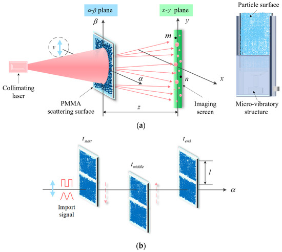
Figure 1.
Optical path and motion in the vibrating particle scattering device. (a) Geometric optical path in the vibrating particle scattering device. (b) Motion of the vibrating particle scattering device under external frequency signal.
According to the fundamental theory of speckle formation, the speckle reduction mechanism primarily depends on decreasing the temporal coherence and spatial coherence of the laser. In this work, the designed particle surface homogenizes the laser spot size through particle scattering. Figure 2a shows and compares the laser spot directly emitted and the spot emitted after particle scattering. According to the Nyquist sampling theorem [30], when multiple speckle grains generated by particle scattering are simultaneously integrated in a single detector pixel, a pixel-level spatial averaging effect is introduced, which effectively reduces the measured spatial coherence of the speckle field [10].
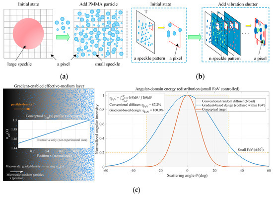
Figure 2.
Mechanism of low spatio-temporal coherence in the vibrating particle scattering device. (a) Reduction in spatial coherence by micro-particles via spatial averaging at the pixel level. (b) Temporal coherence reduction via micro-vibration-induced speckle superposition within the exposure time. (c) Conceptual illustration of a gradient-enabled effective-medium scattering layer and its effect on angular-domain energy redistribution, demonstrating controlled confinement of scattered energy within a small field of view. (orange arrow: direction of increasing Particle density (graded packing). Blue dots: representative particles (schematic). Gray background gradient: conceptual density gradient/effective-medium variation. Inset line: conceptual (schematic, not experimental). Gray shaded region (right): small ±θFoV. Dashed line: conceptual target profile for comparison (schematic)).
The micro-vibration structure designed in this study enhances the speckle pattern within exposure time T by introducing vibrations. Figure 2b shows a comparison of the speckle pattern intensity distributions with and without the micro-vibration structure. Using pattern superposition, we increased the diversity of speckles captured in a single exposure frame. This process induces a time-averaging effect on the speckle, which decreases the temporal coherence. The SSS simultaneously reduces speckles in both temporal and spatial dimensions to enhance the imaging quality while preserving high clarity in the displayed image. Besides the pixel-level spatial averaging illustrated in Figure 2a, the spatial coherence of the scattered field can also be interpreted from an angular-domain perspective. To further clarify the role of the spatially varying effective refractive index, Figure 2c conceptually illustrates the gradient-enabled effective-medium layer and its effect on angular-domain energy redistribution. Through the introduction of a controlled gradient in particle density, a spatially varying effective refractive index forms at the macroscale, which changes the statistical weighting of scattering events. Consequently, the scattered energy is preferentially redistributed within a limited angular range (±30°), achieving an enhanced angular consistency and improved optical efficiency for small-FOV micro-projection systems. Note that the illustrated profile is schematic and aims to highlight the design principle rather than represent measured refractive-index data.
When the SSS experiences a periodic reciprocating motion along the β-axis, the phase of each scattering particle changes upon laser illumination. The externally applied random vibration frequency modulates the velocity of motion, as illustrated in Figure 1b. In one reciprocating period (tstart-tmiddle-tend), the laser beam continuously irradiates the particle scattering surface, where the light coverage area is denoted as l × l. Specifically, the particle scattering surface is divided into two regions, which alternately switch positions under the applied frequency to ensure persistent optical coverage on the upper scattering region throughout the motion cycle. This macroscopic periodic modulation creates a dynamic scattering phase grating effect, where the time-dependent positional permutation of scattering elements introduces controlled phase modulation to the transmitted wavefront. The resultant spatiotemporal modulation of scattering parameters enables programmable manipulation of light-matter interactions while preserving the beam collimation integrity. From a macroscopic perspective, over one complete cycle, the motion process of the particle scattering surface is
where is the mean oscillation velocity of the scattering surfaces across varying vibrational frequencies, and l is the characteristic length of the laser-irradiated scattering region.
This configuration induces an amplitude random walk phenomenon at each observation point on the detection plane, which causes time-dependent intensity fluctuations in the speckle pattern. To systematically investigate the speckle suppression effect of the SSS, the most crucial method was to analyze its spatiotemporal correlation function.
To comparatively analyze the speckle suppression efficacy between systems with and without the SSS, we conducted a temporal coherence function analysis for points m and n in Figure 1a. Here, the α–β plane represents the particle scattering surface, and the x–y plane denotes the detection surface. When the laser is vertically irradiated onto the particle scattering surface, the relationship between the moving particle scattering field and the received field is [10]
where A is the amplitude, a0 is a constant, and Φd is the phase introduced by the particle scattering surface.
Phase distribution Φd of the particle scattering surface in the designed device is essentially related to the scattering intensity distribution Isca and wavelength-dependent scattering efficiency Qsca as follows:
where ϕtopo(d) is the baseline phase modulation from the surface topography, and is the dynamic phase shift induced by vibration.
Scattering efficiency Qsca follows Mie’s theory [31]:
where an and bn are Mie coefficients determined by the particle size and refractive index contrast.
When Qsca reaches its peak, Mie resonance enhancement occurs, which affects the distribution of the spatial coherence length:
where lc is the spatial coherence length.
The dependency relationships in Equations (3)–(5) ensure the final phase distribution. This process encodes both structural scattering characteristics and dynamic modulation effects. Consequently, by adjusting the geometric parameters of the particles and dynamically modulating the vibration frequency, one can effectively control the statistical properties of the speckle pattern.
By systematically analyzing the spatial coherence properties of a speckle field, the time-delay response relationship between an observation point m and a reference point n in the speckle field can be established. When point n in the speckle field is considered the corresponding observation position of point m after time delay τ, its temporal autocorrelation function is as follows:
where ⟨⋅⟩ denotes the ensemble average.
When the spatial coordinates of point m are , the coherence time τc between points m and n is
where
To approximate the scattering characteristics of a randomly rough surface in practical scenarios, the spatial distribution of the amplitude k(α1,β1) k*(α2,β2) in Equation (7) is the autocorrelation function Rk(α1-α2,β1-β2) of the amplitude point spread function of the particle scattering surface. According to Fourier optics [32], when the CCD photosensitive surface of the imaging system is circular, the autocorrelation function of the corresponding amplitude point spread function can be approximated as
where J1 is the first-order Bessel function, D is the exit pupil aperture of the imaging system, λ is the wavelength of the incident light, and z is the distance from the rough surface to the imaging plane.
Assuming that phase distribution Φd follows a Gaussian random field with zero mean, its statistical properties can be fully characterized by standard deviation σd and overall autocorrelation length rd. Then, the coherence time τc of Equation (7) can be approximated as
The inherently stochastic nature of speckle phenomena necessitates the application of statistical optics principles for comprehensive characterization.
To systematically evaluate the speckle suppression performance of the SSS, we define the normalized dynamic speckle contrast as the ratio between dynamic and static speckle contrasts
where C0 is the static speckle contrast, is the vibration velocity of scattering surfaces, lc is the spatial coherence length from Equation (5), τc is the temporal coherence time defined in Equation (10), λ is the incident wavelength, z is the distance from the rough surface to the imaging plane, l is the length of the particle scattering surface, f is the random vibration frequency, D is the exit pupil aperture of the imaging system, and T is the exposure time.
The moving distance of the particle scattering surface affects the temporal integration of the speckle field, which affects the speckle contrast and visibility. This moving distance depends on the imaging system distance and characteristics of the rough surface. The theoretical equation for the temporal integration of the speckle is Equation (12) [10]:
where RT(τ) is the temporal weighting function, KT(τ) is the autocorrelation function of RT(τ), and M is the number of theoretical degrees of freedom in time-integrated speckle scattering.
The speckle suppression effect (C) of the system can be approximated as
where σI is the standard deviation of the speckle pattern intensity, and is the mean intensity of the speckle pattern.
To systematically investigate the incoherent superposition of intensity patterns from moving scattering surfaces, we established a quantitative relationship between the number of uncorrelated frames (N) and the vibration frequency (f):
where T is the exposure time, and τc is the coherence time.
As analyzed by Equation (14), vibration frequency f is correlated with exposure time T. When f increases, the number of uncorrelated speckle patterns N superposed within T increases. When T exceeds the rotational period 1/f, N becomes independent of the frequency, and the suppression effect of frequency approaches saturation. For sufficiently large N (typically N ≥ 10), the speckle contrast in Equation (13) must be modified by introducing a stochastic scaling constant to account for this saturation phenomenon.
Equation (15) describes the speckle reduction mechanism in surface scattering in a free-space optical path. We developed a model to characterize the speckle formation in free-space optical paths. The effects of the geometric parameters, vibration frequency, and imaging distance of the scattering surface on the speckle suppression were investigated. Finally, these simulation results were experimentally validated to evaluate the speckle suppression effectiveness.
3. Simulation of the Effect of Key Parameters on Speckle Suppression
3.1. Effect of Different Parameters of a Single Particle on the Scattering Phase Angle
To simulate the influence of different parameters of a single particle on the scattering phase angle, based on the Mie scattering theory [31], we simulated the scattering distribution of a single particle using MATLAB R2024b.
The scattering phase angle of a single particle is affected by several key parameters: the particle diameter, wavelength, and refractive index. To enhance the clarity of the speckle pattern, the scattering particles should have high transmittance with no or minimal absorption in the surrounding environment. Therefore, spherical microparticles made of polymethyl methacrylate (PMMA) were selected.
According to Mie scattering theory, the scattering efficiency of PMMA particles varies with the wavelength due to the changing interaction between incident light and the particle. As Figure 3 shows, the scattering particles exhibit relatively stable scattering efficiency across the wavelength range of 0.4–0.6 μm with a refractive index of 1.49. The scattering efficiency Qsca maintains a near-constant value of in this range. In Figure 3, Qsca greatly increases for wavelengths beyond 0.6 μm, which is consistent with theoretical predictions from the Mie scattering formalism. At the target wavelength of 0.65 μm, scattering efficiency Qsca and forward scattering intensity I(0°) depend on particle size r, as is numerically demonstrated in Figure 4a. The red curve is the light intensity distribution I1 in the perpendicular scattering plane; the blue curve is the light intensity distribution I2 in the parallel scattering plane.
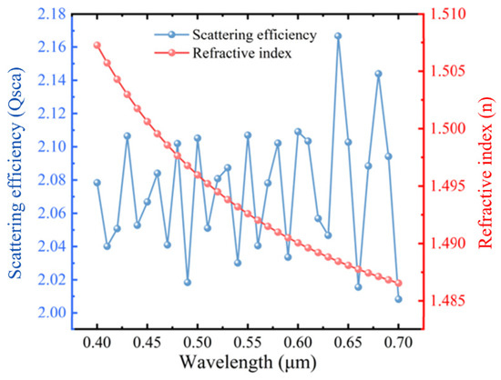
Figure 3.
Wavelength dependence of scattering efficiency and refractive index for polymethyl methacrylate particles.
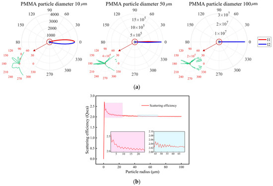
Figure 4.
Scattering intensity and efficiency versus particle size. (a) Scattering intensity profiles versus particle size. (b) Scattering efficiency profiles versus particle size.
As the polar plot of Figure 4a shows, increasing the particle diameter enhances the forward-scattering dominance, where both orthogonal polarization components converge toward the 0° direction. For PMMA particles with a diameter of 100 μm (radius r = 50 μm), the angular scattering profile had a pronounced forward lobe (FWHM < 30°), where the normalized intensity at 0° was Imax = 7.6 × 10⁵, which is significantly larger than the observed values for smaller particles (Figure 4a). This strong forward-scattering concentration aligns with the Fraunhofer diffraction condition (the theoretical limit for r = 50 μm, λ = 650 nm):
Figure 4b reveals the oscillatory behavior in scattering efficiency (Qsca) with increasing particle size, which stabilizes near Qsca=2.02±0.05 particles with radii r ≥ 50 μm (diameters d ≥ 80 μm). In incoherent imaging systems, the particle size critically modulates the spatial scattering distributions and coherence characteristics. To optimize the imaging quality, we aim to balance between enhancing the spatial scattering efficiency and reducing the coherence. Thus, the impact of particle size on the spatial scattering characteristics and coherence must be considered. This balance can be achieved by strategically integrating speckle-generating particles and optimizing the coherence area. Based on the analysis results from Figure 4, PMMA particles with a diameter of 100 μm were selected for use with 650 nm wavelength light since they exhibit strong forward scattering characteristics.
3.2. Effect of the Scattering Surface Parameters on the Speckle Field
The statistical and structural properties of the scattering surface play a crucial role in determining the characteristics of the speckle field. Equation (10) analyzes the effect of particle-formed Gaussian rough surfaces on the speckle coherence time. The most critical parameters are the standard deviation σd and overall autocorrelation length rd. Based on the work of Wang et al. [31], this study required more than 90% completely incoherent forward-scattered light energy. Assuming a uniform particle distribution with stacking effects, the PMMA particle concentration on the 800 × 800 μm substrate should be set to 4 µm−2.
Figure 5 shows the relationship between the particle size, rough surface coherence length, and autocorrelation function of the particle scattering surface. The horizontal (d1) and vertical (d2) autocorrelation lengths determine the overall autocorrelation length (rd) of the surface.
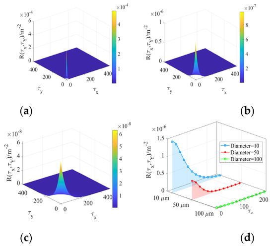
Figure 5.
Coherence length and autocorrelation function versus particle size for rough surfaces (the particle concentration was 4 µm−2). (a) Polymethyl methacrylate (PMMA) particle diameter of 10 μm. (b) PMMA particle diameter of 50 μm. (c) PMMA particle diameter of 100 μm. (d) Autocorrelation profiles.
In Figure 5, the coherence length varies with increasing PMMA particle size. There is a positive correlation between the particle size and the coherence length of the rough surface. Compared with Figure 5a–d, the diameters of particles are higher, the contour of the autocorrelation function for the particle scattering surface is flatter, and the peak value is lower. The simulations indicate that at a particle concentration of 4 µm−2, the surface decorrelation is optimal for PMMA particles with a size of 100 μm. Based on Figure 6, the effect of different particle concentrations on the roughness of the particle scattering surface was further analyzed.
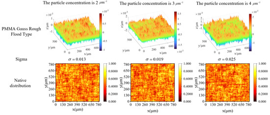
Figure 6.
Three-dimensional distribution and normalized surface profiles versus particle concentration.
The standard deviation σd of the scattering surface varies with different particle concentrations. When the particle concentration per unit area increases, the standard deviation σd of the rough surface increases, which roughens the surface profile. The cases in Figure 6 had particle concentrations of 2 µm−2, 3 µm−2, and 4 µm−2, where the surface standard deviation increases with higher particle concentration. When the particle concentration is 4 µm−2, the corresponding surface standard deviation is 0.0025. Based on the results from Figure 5 and Figure 6, the effect of different roughness values and coherence lengths on the speckle field correlation function was investigated, as shown in Figure 7.
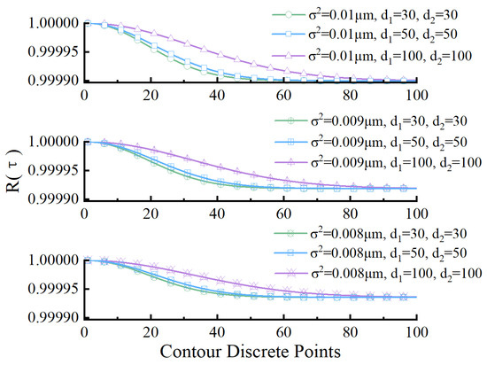
Figure 7.
Speckle correlation versus particle coherence length and surface variance.
Figure 7 analyzes key parameters that affect the correlation of the particle scattering field: overall autocorrelation length rd and standard deviation σd of the surface. A longitudinal comparison uses data points of identical colors but different shapes. It examines the effect of the surface variance (σd2) on the temporal autocorrelation of the speckle field. When σd2 increases, the temporal autocorrelation more quickly decays, which causes a quicker reduction in speckle pattern correlation. Increased surface roughness enhances the scattering component of the laser, which intensifies scattering and weakens the correlation.
A horizontal comparison uses data points of different colors but identical shapes. It evaluates the effect of the overall autocorrelation length rd on the temporal autocorrelation of the speckle field. Smaller (d1, d2) values cause a more pronounced decay in the temporal autocorrelation R(τ). Reducing the autocorrelation length of the rough surface amplifies the speckle intensity after scattering from PMMA particles, which accelerates the decline in speckle pattern correlation. The results in Figure 7 are consistent with the conclusions in Figure 5.
3.3. Effect of the System Parameters on the Speckle Suppression
The speckle suppression effect (C) of the system is critically affected by the exit pupil aperture (D) and imaging distance (z), as derived from the decoherence analysis of particle scattering surfaces (Equation (15)). These parameters modulate the autocorrelation function of the amplitude point spread function (Rk) and consequently govern the temporal autocorrelation (R(τ)) characteristics of the speckle field. Figure 8 systematically quantifies these relationships through numerical simulations.
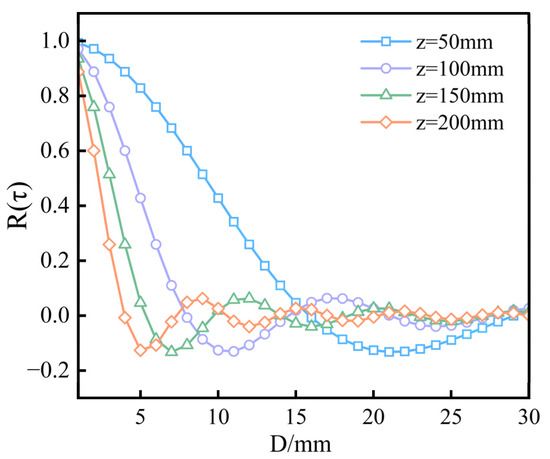
Figure 8.
Temporal autocorrelation of speckle versus aperture at various distances.
In the measurement of subjective speckle, the exit pupil aperture of the imaging system affects the speckle grain size on the image plane [33]. Specifically, according to the study by Roelandt et al. [9], the average area of speckle grains can be calculated as follows:
where ΩL is the solid angle subtended by the exit pupil of the camera lens at the image plane; λ is the central wavelength of the incident laser; D is the exit pupil aperture of the imaging system; and FA is the distance between the aperture stop and the photosensitive chip, which is approximately equal to the focal length of the front imaging lens of the camera.
According to the Nyquist sampling theorem [30], the pixel size of the detector should be at least twice the area of the speckle grains. Based on this analysis, the selection of the imaging distance and aperture is closely related to the characteristics of the detector. To achieve high-resolution imaging, this study selected a 5-megapixel camera, model MV-SUA502M, which was manufactured by Mightex (North York, ON, Canada). The CCD chip of the camera had a resolution of 2592 × 1944 with a pixel size of 2.2 × 2.2 µm2. This camera was equipped with an f8 focal length lens for imaging, and the exit pupil diameter of the imaging system was 6 mm. When the laser wavelength was 650 nm, the average area of the speckle grains was 0.24 µm, which is much smaller than the pixel size of 2.2 µm the camera. The fast decorrelation imaging distance that corresponded to this aperture was approximately 140 mm.
3.4. Effect of the Theoretical and Practical Speckle Degrees of Freedom on the Speckle Contrast
In a speckle suppression analysis, there is an approximate proportional dependence between the free parameter that governs the ideal speckle contrast (M) and the corresponding parameter in our proposed functional model (N). The determination of these parameters is intrinsically linked to the external vibration frequency (f ) analyzed in Figure 9. From Equations (14) and (15), to quantitatively characterize the relationship between M and N, we introduced a frequency-independent stochastic scaling constant k. This parameter is not a fitting variable but represents an effective reduction in the number of statistically independent speckle realizations caused by a finite exposure time, detector averaging, and device-specific motion constraints.
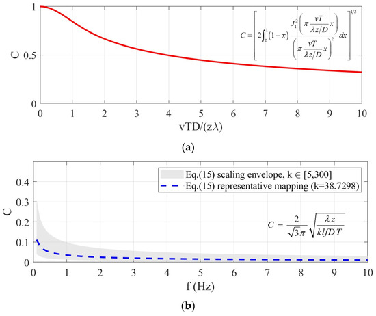
Figure 9.
Trend consistency between the ideal Goodman model and the frequency-dependent response of the speckle suppression structure. (a) Ideal speckle contrast predicted by the Goodman integral model as a function of the normalized displacement parameter vTD/λz. (b) Frequency-dependent scaling behavior of the proposed speckle suppression structure, shown as a frequency-independent scaling envelope derived from Equation (15).
According to Equations (12) and (15), the theoretical speckle contrast is C = 1/M1/2. When the approximate image resolution scale (λz/D) in the imaging system remains constant, the speckle contrast decreases with increasing displacement distance (vT) of the rough surface. Thus, an increase in rough surface motion velocity decreases the speckle contrast.
In comparison with the theoretical analysis, the actual speckle contrast C decreased with an increase in externally applied frequency f, as shown in Figure 9b. Although the absolute contrast values differ from the ideal Goodman prediction, the downward trend is consistent with the theoretical expectation. When C decreases, achieving M ≈ kN requires an increase in the externally applied frequency f of the PMMA rough surface.
To achieve a decrease in speckle contrast C with increasing scaling factor k, it is necessary to increase the required vibration frequency f of the PMMA rough surface. However, increasing frequency f does not always improve the performance since its optimal range is ultimately constrained by the exposure time T. According to the analysis of Equation (14), the frequency-dependent speckle contrast requires the corresponding frequency and exposure time to satisfy the relationship of 1/f ≥ T.
4. Experiment and Results Analysis
Based on the selected parameters from the simulation results in the previous section, an experimental apparatus was setup as shown in Figure 10. The incident laser had a wavelength of 650 nm and consisted of a collimated and expanded light source.
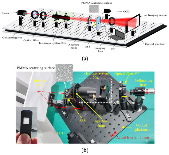
Figure 10.
Experimental optical path diagram for speckle suppression in miniaturized laser projectors using speckle suppression structure (SSS). (a) Theoretical optical path diagram. (b) Experimental optical path diagram.
The SSS was fabricated by integrating a high-transmittance viscous polymer film between the particulate scattering surface and a micro-vibration structure. The scattering surface consisted of randomly distributed PMMA particles with a controlled diameter d = 100 µm, and the minimum achievable surface roughness scale (dictated by practical constraints of the micro-vibration structure aperture length) was lmin = 4 × 4 mm. The distance from the SSS to the imaging screen was z = 140 mm. The camera had a CCD chip with a resolution of 2592 × 1944 and a pixel size of 2.2 × 2.2 µm2, and it was equipped with an M12-f8 focus imaging lens. Considering the integration time of the human eye, the exposure time was set to 20 ms [34]; according to Equation (14), the maximum frequency that affected the scattering contrast reduction was 50 Hz.
Figure 10b shows the SSS depicted in the lower-left quadrant, which incorporated a high-transmittance viscous polymer film with transmittance > 95% across the visible spectrum (400–700 nm). The viscosity of the adhesive film had minimal variation (<2% relative change) under vibrational excitation frequencies of 0–50 Hz.
A function generator drove the system with a cosine waveform (amplitude range: ±5 V; frequency range: 0–50 Hz) to modulate the translational velocity of the PMMA scattering surface of the SSS along the β-axis. This velocity modulation directly governed the speckle suppression effect C.
To investigate the impact of the particle concentration on the surface roughness statistics, two scattering surfaces with identical particle concentrations (3.2 × 10³ particles/mm) but distinct spatial distributions were fabricated (Figure 11).
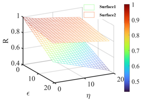
Figure 11.
Evolution of autocorrelation functions for scattering surfaces with distinct spatial distributions.
In Figure 11, surface 1 exhibited faster autocorrelation decay (R1 >R 2), which indicates that it was rougher than scattering surface 2. According to the simulation results in Section 3.2, increased surface roughness corresponds to greater surface variance fluctuations, which leads to a more complex speckle intensity distribution and a faster decorrelation process. In the experimental stage, PMMA scattering surface 1 was selected for experimental validation due to its superior speckle suppression potential.
To validate the speckle suppression effect of the SSS, we primarily analyzed the changes in speckle patterns before and after vibration was introduced. When the applied frequency increased, speckle patterns with varying light intensity distributions were collected, as shown in Figure 12a–g. All speckle images were acquired under identical optical configuration, camera, magnification, and exposure conditions. Therefore, the detector-induced spatial averaging effect remains unchanged throughout the measurements.
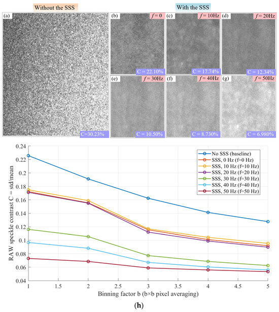
Figure 12.
Speckle patterns at different vibration frequencies and detector-limited speckle contrast behavior. (a) Speckle patterns without the SSS. (b–g) Speckle patterns with the SSS. The frequencies are 0–50 Hz with intervals of 10 Hz. The corresponding measured speckle contrast values are shown. (h) Raw speckle contrast as a function of the pixel binning factor b, illustrating the effect of detector spatial averaging (βdet). All measurements were taken under identical optical configuration, camera, magnification, and exposure conditions.
Under collimated laser illumination without the SSS, the measured speckle contrast on the projection screen is 30.23%, corresponding to a detector-limited speckle contrast imposed by the finite pixel size of the imaging sensor. With SSS introduced and driven at increasing vibration frequencies, the measured speckle contrast decreases from 22.10% at 0 Hz to 6.98% at 50 Hz. This pronounced frequency-dependent reduction indicates an additional decorrelation mechanism beyond the detector-limited baseline.
Note that the proportional factor k introduced in the previous model represents an effective statistical factor considering the combined influence of a finite exposure time, detector spatial averaging, and device-specific motion constraints, which together reduce the number of statistically independent speckle realizations. To clearly distinguish measurement-system effects from physical speckle suppression mechanisms, we explicitly separated the contribution associated with the detector and imaging chain and denoted it as βdet. Accordingly, the measured speckle contrast can be expressed as
where βdet represents the detector transfer factor determined by pixel averaging, the finite fill factor, and the imaging chain. Under the same camera, magnification, and exposure conditions, βdet can be viewed as approximately constant or weakly varying. Cphys denotes the physical statistical averaging effect introduced by the SSS, which primarily comes from vibration-induced temporal decorrelation.
To quantitatively assess the influence of detector averaging, we performed a pixel binning-based numerical analysis as a reference for βdet, as shown in Figure 12h. The results show that detector-induced spatial averaging, governed by pixel integration and the imaging chain, acts only as a constant scaling factor under fixed detection conditions and cannot account for the observed frequency-dependent contrast reduction. Therefore, the contrast decrease shown in Figure 12a–g is primarily attributed to the vibration-induced speckle decorrelation introduced by the SSS rather than by detector effects.
While Figure 12 illustrates a clear frequency-dependent contrast reduction, it is necessary to further clarify the spatial correlation scale of the measured speckle patterns to differentiate between scattering particle size and speckle size on the detector plane. To this end, we introduced a quantitative characterization based on the autocorrelation function (ACF). The corresponding correlation radii rFWHM and r1/e, defined as the radii at the full width at half maximum and the 1/e decay of the ACF, respectively, were extracted in units of pixels (px) and are shown in Figure 13a for the raw speckle ACFs and Figure 13b for the bandpass ACFs.
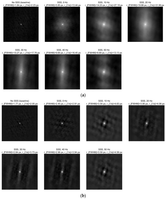
Figure 13.
Autocorrelation function (ACF) analysis of speckle spatial correlation scales at different vibration frequencies. (a) Two-dimensional autocorrelation functions (RAW ACFs) of the raw speckle images and the extracted spatial correlation radii. (b) Two-dimensional autocorrelation functions (bandpass ACFs) of bandpass-filtered speckle images and the corresponding spatial correlation radii.
As Figure 13 illustrates, the speckle correlation length on the detector plane spans multiple pixels rather than being far below a single pixel, demonstrating that the measured speckle patterns are not dominated by deep sub-pixel sampling effects. This outcome verifies that the system does not operate in an extreme undersampling regime in which temporal averaging will become ineffective. Rather, the temporal decorrelation induced by vibration can still play a major role in reducing speckle contrast under the present detector-limited conditions.
Based on the spatial correlation analysis, we further quantified the vibration-induced statistical decorrelation of speckle patterns by evaluating the similarity between speckle images acquired at different excitation frequencies, as depicted in Figure 14. Zero-mean normalized cross-correlation (ZNCC) were employed as complementary similarity metrics. Figure 14a shows the ZNCC between the speckle pattern acquired at frequency f and the 0 Hz baseline, calculated within a fixed region of interest of 160 × 160 pixels. As the applied vibration frequency rises from 0 to 50 Hz, the ZNCC value decreases monotonically, implying a progressive loss of statistical similarity between speckle realizations. To further visualize this decorrelation behavior, Figure 14b presents two-dimensional ZNCC maps as a function of spatial displacement (Δx, Δy) between the 0 Hz reference and speckle patterns acquired at different vibration frequencies. At 0 Hz, a pronounced correlation peak is seen at zero displacement. With increasing vibration frequency, the correlation peak is progressively suppressed and broadened, and its peak amplitude falls from unity to approximately 0.67 at 50 Hz. This suppression of the central correlation peak directly evidences the vibration-induced temporal decorrelation of the speckle field.
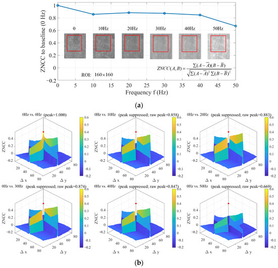
Figure 14.
Correlation analysis of speckle patterns under different applied vibration frequencies. (a) Zero-mean normalized cross-correlation (ZNCC) between speckle patterns acquired at frequency f and the 0 Hz baseline, calculated over a fixed region of interest (ROI) indicated by the red boxes (160 × 160 pixels) in the inset images. The blue curve represents the zero-shift ZNCC value, characterizing the statistical similarity within the same spatial region. (b) Two-dimensional ZNCC maps as a function of spatial displacement (Δx, Δy) between the 0 Hz reference speckle pattern and those acquired at 10–50 Hz. The red dot marks the zero-displacement (Δx = 0, Δy = 0) correlation peak, whose value corresponds directly to the ZNCC values plotted in (a).
Notably, the correlation does not disappear completely within the studied frequency range, reflecting the practical constraints imposed by finite exposure time, detector spatial averaging, and limited mechanical displacement. These factors collectively yield a system-dependent residual correlation level, which exists as a residual speckle contrast floor under the present optical and detection conditions. This behavior aligns with prior research on laser projection and display systems [8,9,10], where residual speckle contrast on the order of several percent has commonly been observed. Therefore, the saturation of speckle contrast at approximately 6–7% in this work should be viewed as a system-level limitation determined by temporal integration, detector sampling, and mechanical modulation efficiency, not a fundamental limitation of the proposed SSS mechanism. Moreover, the consistent trends observed in Figure 12, Figure 13 and Figure 14 together confirm that the dominant speckle suppression derives from vibration-induced temporal decorrelation, while the remaining contrast is dictated by the measurement and modulation constraints of the compact projection system.
Finally, the performance of the proposed SSS was compared with representative speckle suppression approaches, as shown in Table 1. Under the present optical configuration and detection conditions, the proposed scattering device achieves a comprehensive spatiotemporal coherence reduction, resulting in a measured speckle contrast of approximately 6.98%. Note that this value reflects a system-level performance floor, limited by a finite exposure time, detector sampling, and practical mechanical modulation; that is, it is not a fundamental limitation of the proposed SSS mechanism.

Table 1.
Comparison of different speckle suppression methods and their effects.
Notably, the proposed SSS shows distinctive advantages under small-angle imaging conditions, which are extremely relevant to compact laser projection systems. As shown in Table 1, existing approaches are typically optimized for near-axis or moderate angular configurations and do not overtly control angular energy redistribution within a defined FOV. In contrast, the proposed method is overtly optimized for a small FOV of ±30°, within which the speckle contrast variation stays below 2%. This result indicates that the proposed approach effectively addresses the important trade-off between speckle suppression and angular efficiency, making it suitable for compact and dynamically adaptable laser projection architectures.
5. Conclusions
This study presented the SSS, which enables microdisplay imaging within an angular range of 0°–30° while suppressing the spatiotemporal coherence. By integrating multi-scattering-induced virtual sub-sources (100 µm particles at 650 nm) with dynamic vibration modulation optimal at 50 Hz, the device reduced the spatiotemporal coherence from 30.23% to 6.98%, which surpassed the performance of conventional diffusers in terms of angular uniformity and response time. Additionally, this value represents the system-level performance constrained by finite exposure time, detector spatial averaging, and mechanical modulation, not a fundamental limit of the SSS mechanism. Within these practical constraints, the proposed approach shows pronounced frequency-dependent decorrelation behavior, thus verifying its rapid and controllable coherence modulation. Through Mie scattering simulations and autocorrelation modeling, we optimized the following critical parameters: high transmittance: 92.4 to ±1.2%; low absorption: 2.8 to ±0.5%; and Gaussian-distributed particle density: 3.2 × 10³ particle/mm. Experimental validation confirmed the frequency-dependent decorrelation (τc∝f−0.82±0.04), which demonstrates rapid coherence control. The solution addresses the challenges of miniaturized laser projection displays (e.g., AR/VR display) in achieving a low speckle level of <7% within a small angular range. It provides a foundational structure for compact laser projection systems with improved spatiotemporal performance.
Author Contributions
Conceptualization, X.Z.; Methodology, Y.Z.; Software, H.L.; Validation, Y.Z. and X.Z.; Formal analysis, H.L.; Resources, X.S. and W.L.; Writing—original draft, Y.Z.; Writing—review & editing, X.Z.; Supervision, S.Z., X.S. and W.L.; Project administration, S.Z. and W.L.; Funding acquisition, S.Z. All authors have read and agreed to the published version of the manuscript.
Funding
We acknowledge financial support from the Scientific Research Program of Shaanxi Provincial Education Department (No.21JY017).
Data Availability Statement
The original contributions presented in this study are included in the article. Further inquiries can be directed to the corresponding authors.
Conflicts of Interest
The authors declare no conflicts of interest.
References
- Cao, H.; Chrik, R.; Bittner, S.; Friesem, A.A.; Davidson, N. Complex lasers with controllable coherence. Nat. Rev. Phys. 2019, 42, 156–168. [Google Scholar] [CrossRef]
- Guo, D.; Yuan, G.; Wang, Z.; Wu, J. Dynamic control of laser source current in projection display. Opt. Eng. 2019, 58, 053108. [Google Scholar] [CrossRef]
- Evered, C.; Li, K.; Fan, Y.; Zhang, B.; Roula, A. A review of light sources used for laser speckle reduction in display and imaging applications. Opt. Laser Technol. 2025, 183, 112407. [Google Scholar] [CrossRef]
- Chen, Y.; Xiang, J.; Gao, F.; Zhu, L.; Xu, L. Evaluation and configuration of light sources with suppressing speckle and maintaining color gamut in laser displays. Opt. Laser Technol. 2025, 184, 112533. [Google Scholar] [CrossRef]
- Zhao, H.; Yue, D.; Zhang, B. The Technology and Development of Laser Display Optical Screens. Int. Conf. Disp. Technol. 2023, 54, 21–26. [Google Scholar] [CrossRef]
- Dong, L.; Guo, D.; Yuan, G. Study on speckle suppression of RGB color semiconductor laser driven by high frequency current. Int. Conf. Disp. Technol. 2024, 55, 1546–1549. [Google Scholar] [CrossRef]
- Goodman, J.W. Statistical properties of laser speckle patterns. In Laser Speckle and Related Phenomena; Springer: Berlin/Heidelberg, Germany, 1975. [Google Scholar]
- Cui, Z.; Wang, A.-T.; Wang, Z.; Wang, S.-L.; Gu, C.; Ming, H.; Xu, C.-Q. Speckle suppression by controlling the coherence in laser based projection systems. J. Disp. Technol. 2015, 11, 330–335. [Google Scholar] [CrossRef]
- Roelandt, S.; Meuret, Y.; Jacobs, A.; Willaert, K.; Janssens, P.; Thienpont, H.; Verschaffelt, G. Human speckle perception threshold for still images from a laser projection system. Opt. Express 2014, 22, 23965–23979. [Google Scholar] [CrossRef]
- Freund, I. Joseph W. Goodman: Speckle Phenomena in Optics: Theory and Applications. J. Stat. Phys. 2008, 130, 413–414. [Google Scholar] [CrossRef]
- Mahler, S.; Eliezer, Y.; Yılmaz, H.; Friesem, A.A.; Davidson, N.; Cao, H. Fast laser speckle suppression with an intracavity diffuser. Nanophotonics 2021, 10, 129–136. [Google Scholar] [CrossRef]
- Xie, L.; Liu, K.; Liu, Z.; Guo, J. High-precision phase retrieval method for speckle suppression based on optimized modulation masks. Opt. Express 2023, 12, 18824–18839. [Google Scholar] [CrossRef] [PubMed]
- Chen, K.; Pan, J.; Jeng, S. A liquid crystal microlens array for a low speckle laser projector. Opt. Laser Technol. 2025, 184, 112415. [Google Scholar] [CrossRef]
- Tong, Z.; Chen, X. Principle, design and fabrication of a passive binary micro-mirror array (BMMA) for speckle reduction in grating light valve (GLV) based laser projection displays. Sens. Actuators A-Phys. 2014, 210, 209–216. [Google Scholar] [CrossRef]
- Xu, Q.; Lapchuk, A.; Le, Z.; Cai, D.; Chen, X.; Li, D.; Mao, H.; Kryuchyn, A. Spatial dimension expansion of incoherent optical field in a multimode fiber scheme for speckle suppression. Opt. Laser Technol. 2023, 168, 107662. [Google Scholar] [CrossRef]
- Chen, A.; Zhang, W.; Zhou, X.; Liu, J.; Zheng, W. Study on the spatiotemporal coherence and passive speckle suppression of the edge-emitting broad-area laser diode. J. Opt. 2025, 27, 045610. [Google Scholar] [CrossRef]
- Tong, Z.; Sun, C.; Ma, Y.; Wang, M.; Jia, S.; Chen, X. Laser Spatial Coherence Suppression With Refractive Optical Elements Toward the Improvement of Speckle Reduction by Light Pipes. IEEE Access 2019, 7, 172190–172198. [Google Scholar] [CrossRef]
- Tong, Z.; Sun, C.; Ma, Y.; Wang, M.; Jia, S.; Chen, X. Design and implementation of passive speckle reduction in laser projector with refractive optical element and lenslet integrator. Optik 2022, 252, 168531. [Google Scholar] [CrossRef]
- Kim, J.; Han, J.; Jeong, J. Periodic reference subtraction method for efficient background fixed pattern noise removal in Fourier domain optical coherence tomography. Opt. Commun. 2012, 285, 2012–2016. [Google Scholar] [CrossRef]
- Yuan, Y.; Wang, D.; Wang, D.; Wang, D.; Sun, M.; Gao, W.; Zhang, S.; Bi, Y. Influence and evaluation of vibrating screen methods on subjective speckle reduction. In SPIE 11023, Fifth Symposium on Novel Optoelectronic Detection Technology and Application; SPIE: Bellingham, WA, USA, 2019; Volume 11023, p. 110234A. [Google Scholar]
- Chen, H.; Pan, J.; Yang, Z. Speckle reduction using deformable mirrors with diffusers in a laser pico-projector. Opt. Express 2017, 25, 18140–18151. [Google Scholar] [CrossRef]
- Jin, C.; Zhou, S.; Sun, X.; Pu, X.; Sun, Q.; Xu, Y.; Liu, W. Laser speckle suppression based on tunable metasurface. Acta Photonica Sin. 2020, 49, 0724001. [Google Scholar]
- Kasazumi, K.; Kitaoka, Y.; Mizuuchi, K.; Yamamoto, K. A Practical Laser Projector with New Illumination Optics for Reduction of Speckle Noise. Jpn. J. Appl. Phys. 2004, 43, 5904–5906. [Google Scholar] [CrossRef]
- Lapchuk, A.; Pashkevich, G.; Prygun, O.; Kosyak, I.; Fu, M.; Le, Z.; Kryuchyn, A. Very efficient speckle suppression in the entire visible range by one two-sided diffractive optical element. Appl. Opt. 2017, 56, 1481–1488. [Google Scholar] [CrossRef]
- Lapchuk, A.; Gorbov, I.; Prygun, A.; Morozov, Y. Speckle- and interference fringes-free illumination system with a multi-retarder plate. Opt. Express 2023, 31, 19173–19188. [Google Scholar] [CrossRef]
- Liang, C.; Zhang, W.; Wu, Z.; Rui, D.; Sui, Y.; Yang, H. Beam Shaping and Speckle Reduction in Laser Projection Display Systems Using a Vibrating Diffractive Optical Element. Curr. Opt. Photon. 2017, 1, 23–28. [Google Scholar] [CrossRef][Green Version]
- Le, Z.; Liu, Z.; Qiu, Y.; Ren, H.; Dai, Y. Fabrication of ultrathin flexible diffractive optical elements (DOEs) and application for laser speckle suppression. Opt. Laser Technol. 2022, 159, 107223. [Google Scholar] [CrossRef]
- Chen, A.; Zhang, W.; Zhou, X.; Liu, J.; Zheng, W. Spatial coherence research and passive speckle suppression for edge-emitting broad-area semiconductor lasers. J. Opt. 2024, 26, 045607. [Google Scholar] [CrossRef]
- Fan, Z.; Liu, J.; Ma, Y.; Wang, M.; Jia, S.; Chen, X.; Tong, Z. Equal-intensity beam splitter realization by wire grid polarizers for passive laser speckle reduction. Appl. Opt. 2023, 62, 2862–2868. [Google Scholar] [CrossRef]
- Kirkpatrick, S.J.; Duncan, D.D.; Wells-Gray, E.M. Detrimental effects of speckle-pixel size matching in laser speckle contrast imaging. Opt. Lett. 2008, 33, 2886–2888. [Google Scholar] [CrossRef]
- Wang, Y.; Zhao, P.; Gao, W.; Chen, X. Optimization of forward-scattered light energy and de-coherence of Mie scattering for speckle suppression. Opt. Quantum Electron. 2014, 47, 235–246. [Google Scholar] [CrossRef]
- Born, M.; Wolf, E. Principles of Optics, 6th ed.; Pergamon: New York, NY, USA, 1980. [Google Scholar]
- Spaett, A.; Zagar, B.G. Optimal speckle size and signal processing for displacement measurements using a 4f optical setup. Meas. Sci. Technol. 2024, 35, 075013. [Google Scholar] [CrossRef]
- Riechert, F.; Bastian, G.; Lemmer, U. Laser speckle reduction via colloidal-dispersion-filled projection screens. Appl. Opt. 2009, 48, 3742–3749. [Google Scholar] [CrossRef] [PubMed]


Disclaimer/Publisher’s Note: The statements, opinions and data contained in all publications are solely those of the individual author(s) and contributor(s) and not of MDPI and/or the editor(s). MDPI and/or the editor(s) disclaim responsibility for any injury to people or property resulting from any ideas, methods, instructions or products referred to in the content. |
© 2026 by the authors. Licensee MDPI, Basel, Switzerland. This article is an open access article distributed under the terms and conditions of the Creative Commons Attribution (CC BY) license.